EP3171012A2 - Air intake system for a work vehicle with enhanced pre-cleaner serviceability - Google Patents
Air intake system for a work vehicle with enhanced pre-cleaner serviceability Download PDFInfo
- Publication number
- EP3171012A2 EP3171012A2 EP16199597.2A EP16199597A EP3171012A2 EP 3171012 A2 EP3171012 A2 EP 3171012A2 EP 16199597 A EP16199597 A EP 16199597A EP 3171012 A2 EP3171012 A2 EP 3171012A2
- Authority
- EP
- European Patent Office
- Prior art keywords
- cleaner
- intake duct
- cover
- air intake
- duct
- Prior art date
- Legal status (The legal status is an assumption and is not a legal conclusion. Google has not performed a legal analysis and makes no representation as to the accuracy of the status listed.)
- Granted
Links
Images


Classifications
-
- F—MECHANICAL ENGINEERING; LIGHTING; HEATING; WEAPONS; BLASTING
- F02—COMBUSTION ENGINES; HOT-GAS OR COMBUSTION-PRODUCT ENGINE PLANTS
- F02M—SUPPLYING COMBUSTION ENGINES IN GENERAL WITH COMBUSTIBLE MIXTURES OR CONSTITUENTS THEREOF
- F02M35/00—Combustion-air cleaners, air intakes, intake silencers, or induction systems specially adapted for, or arranged on, internal-combustion engines
- F02M35/02—Air cleaners
- F02M35/022—Air cleaners acting by gravity, by centrifugal, or by other inertial forces, e.g. with moistened walls
- F02M35/0223—Air cleaners acting by gravity, by centrifugal, or by other inertial forces, e.g. with moistened walls by centrifugal forces, e.g. cyclones
-
- B—PERFORMING OPERATIONS; TRANSPORTING
- B01—PHYSICAL OR CHEMICAL PROCESSES OR APPARATUS IN GENERAL
- B01D—SEPARATION
- B01D45/00—Separating dispersed particles from gases or vapours by gravity, inertia, or centrifugal forces
- B01D45/12—Separating dispersed particles from gases or vapours by gravity, inertia, or centrifugal forces by centrifugal forces
-
- B—PERFORMING OPERATIONS; TRANSPORTING
- B01—PHYSICAL OR CHEMICAL PROCESSES OR APPARATUS IN GENERAL
- B01D—SEPARATION
- B01D45/00—Separating dispersed particles from gases or vapours by gravity, inertia, or centrifugal forces
- B01D45/12—Separating dispersed particles from gases or vapours by gravity, inertia, or centrifugal forces by centrifugal forces
- B01D45/16—Separating dispersed particles from gases or vapours by gravity, inertia, or centrifugal forces by centrifugal forces generated by the winding course of the gas stream, the centrifugal forces being generated solely or partly by mechanical means, e.g. fixed swirl vanes
-
- B—PERFORMING OPERATIONS; TRANSPORTING
- B01—PHYSICAL OR CHEMICAL PROCESSES OR APPARATUS IN GENERAL
- B01D—SEPARATION
- B01D46/00—Filters or filtering processes specially modified for separating dispersed particles from gases or vapours
- B01D46/0002—Casings; Housings; Frame constructions
- B01D46/0005—Mounting of filtering elements within casings, housings or frames
-
- B—PERFORMING OPERATIONS; TRANSPORTING
- B01—PHYSICAL OR CHEMICAL PROCESSES OR APPARATUS IN GENERAL
- B01D—SEPARATION
- B01D46/00—Filters or filtering processes specially modified for separating dispersed particles from gases or vapours
- B01D46/0002—Casings; Housings; Frame constructions
- B01D46/0005—Mounting of filtering elements within casings, housings or frames
- B01D46/0006—Filter elements or cartridges installed in a drawer-like manner
-
- B—PERFORMING OPERATIONS; TRANSPORTING
- B01—PHYSICAL OR CHEMICAL PROCESSES OR APPARATUS IN GENERAL
- B01D—SEPARATION
- B01D50/00—Combinations of methods or devices for separating particles from gases or vapours
- B01D50/20—Combinations of devices covered by groups B01D45/00 and B01D46/00
-
- F—MECHANICAL ENGINEERING; LIGHTING; HEATING; WEAPONS; BLASTING
- F02—COMBUSTION ENGINES; HOT-GAS OR COMBUSTION-PRODUCT ENGINE PLANTS
- F02M—SUPPLYING COMBUSTION ENGINES IN GENERAL WITH COMBUSTIBLE MIXTURES OR CONSTITUENTS THEREOF
- F02M35/00—Combustion-air cleaners, air intakes, intake silencers, or induction systems specially adapted for, or arranged on, internal-combustion engines
- F02M35/02—Air cleaners
- F02M35/0201—Housings; Casings; Frame constructions; Lids; Manufacturing or assembling thereof
- F02M35/0202—Manufacturing or assembling; Materials for air cleaner housings
- F02M35/0203—Manufacturing or assembling; Materials for air cleaner housings by using clamps, catches, locks or the like, e.g. for disposable plug-in filter cartridges
-
- F—MECHANICAL ENGINEERING; LIGHTING; HEATING; WEAPONS; BLASTING
- F02—COMBUSTION ENGINES; HOT-GAS OR COMBUSTION-PRODUCT ENGINE PLANTS
- F02M—SUPPLYING COMBUSTION ENGINES IN GENERAL WITH COMBUSTIBLE MIXTURES OR CONSTITUENTS THEREOF
- F02M35/00—Combustion-air cleaners, air intakes, intake silencers, or induction systems specially adapted for, or arranged on, internal-combustion engines
- F02M35/02—Air cleaners
- F02M35/0212—Multiple cleaners
- F02M35/0216—Multiple cleaners arranged in series, e.g. pre- and main filter in series
-
- F—MECHANICAL ENGINEERING; LIGHTING; HEATING; WEAPONS; BLASTING
- F02—COMBUSTION ENGINES; HOT-GAS OR COMBUSTION-PRODUCT ENGINE PLANTS
- F02M—SUPPLYING COMBUSTION ENGINES IN GENERAL WITH COMBUSTIBLE MIXTURES OR CONSTITUENTS THEREOF
- F02M35/00—Combustion-air cleaners, air intakes, intake silencers, or induction systems specially adapted for, or arranged on, internal-combustion engines
- F02M35/02—Air cleaners
- F02M35/024—Air cleaners using filters, e.g. moistened
- F02M35/02416—Fixing, mounting, supporting or arranging filter elements; Filter element cartridges
-
- F—MECHANICAL ENGINEERING; LIGHTING; HEATING; WEAPONS; BLASTING
- F02—COMBUSTION ENGINES; HOT-GAS OR COMBUSTION-PRODUCT ENGINE PLANTS
- F02M—SUPPLYING COMBUSTION ENGINES IN GENERAL WITH COMBUSTIBLE MIXTURES OR CONSTITUENTS THEREOF
- F02M35/00—Combustion-air cleaners, air intakes, intake silencers, or induction systems specially adapted for, or arranged on, internal-combustion engines
- F02M35/02—Air cleaners
- F02M35/024—Air cleaners using filters, e.g. moistened
- F02M35/02416—Fixing, mounting, supporting or arranging filter elements; Filter element cartridges
- F02M35/02433—Special alignment with respect to the air intake flow, e.g. angled or in longitudinal flow direction
-
- F—MECHANICAL ENGINEERING; LIGHTING; HEATING; WEAPONS; BLASTING
- F02—COMBUSTION ENGINES; HOT-GAS OR COMBUSTION-PRODUCT ENGINE PLANTS
- F02M—SUPPLYING COMBUSTION ENGINES IN GENERAL WITH COMBUSTIBLE MIXTURES OR CONSTITUENTS THEREOF
- F02M35/00—Combustion-air cleaners, air intakes, intake silencers, or induction systems specially adapted for, or arranged on, internal-combustion engines
- F02M35/02—Air cleaners
- F02M35/024—Air cleaners using filters, e.g. moistened
- F02M35/02475—Air cleaners using filters, e.g. moistened characterised by the shape of the filter element
- F02M35/02483—Cylindrical, conical, oval, spherical or the like filter elements; wounded filter elements
-
- F—MECHANICAL ENGINEERING; LIGHTING; HEATING; WEAPONS; BLASTING
- F02—COMBUSTION ENGINES; HOT-GAS OR COMBUSTION-PRODUCT ENGINE PLANTS
- F02M—SUPPLYING COMBUSTION ENGINES IN GENERAL WITH COMBUSTIBLE MIXTURES OR CONSTITUENTS THEREOF
- F02M35/00—Combustion-air cleaners, air intakes, intake silencers, or induction systems specially adapted for, or arranged on, internal-combustion engines
- F02M35/02—Air cleaners
- F02M35/04—Air cleaners specially arranged with respect to engine, to intake system or specially adapted to vehicle; Mounting thereon ; Combinations with other devices
- F02M35/044—Special arrangements of cleaners in or with respect to the air intake system, e.g. in the intake plenum, in ducts or with respect to carburettors
-
- F—MECHANICAL ENGINEERING; LIGHTING; HEATING; WEAPONS; BLASTING
- F02—COMBUSTION ENGINES; HOT-GAS OR COMBUSTION-PRODUCT ENGINE PLANTS
- F02M—SUPPLYING COMBUSTION ENGINES IN GENERAL WITH COMBUSTIBLE MIXTURES OR CONSTITUENTS THEREOF
- F02M35/00—Combustion-air cleaners, air intakes, intake silencers, or induction systems specially adapted for, or arranged on, internal-combustion engines
- F02M35/02—Air cleaners
- F02M35/04—Air cleaners specially arranged with respect to engine, to intake system or specially adapted to vehicle; Mounting thereon ; Combinations with other devices
- F02M35/048—Arranging or mounting on or with respect to engines or vehicle bodies
-
- F—MECHANICAL ENGINEERING; LIGHTING; HEATING; WEAPONS; BLASTING
- F02—COMBUSTION ENGINES; HOT-GAS OR COMBUSTION-PRODUCT ENGINE PLANTS
- F02M—SUPPLYING COMBUSTION ENGINES IN GENERAL WITH COMBUSTIBLE MIXTURES OR CONSTITUENTS THEREOF
- F02M35/00—Combustion-air cleaners, air intakes, intake silencers, or induction systems specially adapted for, or arranged on, internal-combustion engines
- F02M35/02—Air cleaners
- F02M35/08—Air cleaners with means for removing dust, particles or liquids from cleaners; with means for indicating clogging; with by-pass means; Regeneration of cleaners
-
- F—MECHANICAL ENGINEERING; LIGHTING; HEATING; WEAPONS; BLASTING
- F02—COMBUSTION ENGINES; HOT-GAS OR COMBUSTION-PRODUCT ENGINE PLANTS
- F02M—SUPPLYING COMBUSTION ENGINES IN GENERAL WITH COMBUSTIBLE MIXTURES OR CONSTITUENTS THEREOF
- F02M35/00—Combustion-air cleaners, air intakes, intake silencers, or induction systems specially adapted for, or arranged on, internal-combustion engines
- F02M35/10—Air intakes; Induction systems
- F02M35/10006—Air intakes; Induction systems characterised by the position of elements of the air intake system in direction of the air intake flow, i.e. between ambient air inlet and supply to the combustion chamber
- F02M35/10013—Means upstream of the air filter; Connection to the ambient air
-
- F—MECHANICAL ENGINEERING; LIGHTING; HEATING; WEAPONS; BLASTING
- F02—COMBUSTION ENGINES; HOT-GAS OR COMBUSTION-PRODUCT ENGINE PLANTS
- F02M—SUPPLYING COMBUSTION ENGINES IN GENERAL WITH COMBUSTIBLE MIXTURES OR CONSTITUENTS THEREOF
- F02M35/00—Combustion-air cleaners, air intakes, intake silencers, or induction systems specially adapted for, or arranged on, internal-combustion engines
- F02M35/10—Air intakes; Induction systems
- F02M35/10091—Air intakes; Induction systems characterised by details of intake ducts: shapes; connections; arrangements
-
- F—MECHANICAL ENGINEERING; LIGHTING; HEATING; WEAPONS; BLASTING
- F02—COMBUSTION ENGINES; HOT-GAS OR COMBUSTION-PRODUCT ENGINE PLANTS
- F02M—SUPPLYING COMBUSTION ENGINES IN GENERAL WITH COMBUSTIBLE MIXTURES OR CONSTITUENTS THEREOF
- F02M35/00—Combustion-air cleaners, air intakes, intake silencers, or induction systems specially adapted for, or arranged on, internal-combustion engines
- F02M35/16—Combustion-air cleaners, air intakes, intake silencers, or induction systems specially adapted for, or arranged on, internal-combustion engines characterised by use in vehicles
- F02M35/164—Heavy duty vehicles, e.g. trucks, trains, agricultural or construction machines
-
- B—PERFORMING OPERATIONS; TRANSPORTING
- B01—PHYSICAL OR CHEMICAL PROCESSES OR APPARATUS IN GENERAL
- B01D—SEPARATION
- B01D2279/00—Filters adapted for separating dispersed particles from gases or vapours specially modified for specific uses
- B01D2279/60—Filters adapted for separating dispersed particles from gases or vapours specially modified for specific uses for the intake of internal combustion engines or turbines
Definitions
- the present subject matter relates generally to work vehicle and, more particularly, to an air intake system for a work vehicle that provides for enhanced serviceability of the system's pre-cleaner.
- Work vehicles typically include internal combustion engines that require clean air for use within the combustion process. Since many work vehicles, such as tractors and other agricultural vehicles, operate in fields and other harvesting environments in which the ambient air contains large amounts of dust, plant material and other particulates, an air intake system having an effective filter assembly is required.
- conventional filter assemblies for work vehicles typically include a vortex or cyclone pre-cleaner configured to separate large particulates from the intake air and a porous air filter downstream of the pre-cleaner to provide the final stage of filtering prior to delivering the air into the engine.
- the large particulates separated from the intake air by the pre-cleaner must be removed from the filter assembly.
- such particulates are removed from the filter assembly via an outlet duct using a vacuum generated by the exhaust flow from the engine or using the vehicle's cooling fan.
- the pre-cleaner may become clogged with large particulates. In such instances, it may be desirable to remove the pre-cleaner from the intake duct of the air intake system to allow the pre-cleaner to be cleaned or unclogged.
- the present subject matter is directed to an air intake system for a work vehicle.
- the air intake system may generally include an intake duct having an inner surface and an outer surface.
- the inner surface may define a passageway for directing air in a flow direction through the air intake system.
- the intake duct may also include a pre-cleaner slot defined between the inner and outer surfaces and a support ledge extending circumferentially around at least a portion of an inner perimeter of the intake duct.
- the air intake system may also include a pre-cleaner having an upper wall, a lower wall and a plurality of pre-cleaner elements extending between the upper and lower walls.
- the pre-cleaner may be configured to be installed within the intake duct by inserting the pre-cleaner through the pre-cleaner slot in a direction extending generally perpendicular to the flow direction.
- the air intake system may include a cover configured to be coupled to the intake duct such that the cover extends over the pre-cleaner slot when the pre-cleaner is installed within the intake duct.
- at least a portion of the lower wall may be sealed against the support ledge.
- the present subject matter is directed to an air intake system for a work vehicle.
- the air intake system may generally include an intake duct having an inner surface and an outer surface.
- the inner surface may define a passageway for directing air in a flow direction through the air intake system.
- the inner surface may further define at least one locating groove extending along an inner perimeter of the intake duct.
- the intake duct may also include a pre-cleaner slot defined between the inner and outer surfaces and a support ledge extending circumferentially around at least a portion of the inner perimeter of the intake duct.
- the air intake system may also include a sealing member positioned on the support ledge and a pre-cleaner having an upper wall, a lower wall and a plurality of pre-cleaner elements extending between the upper and lower walls.
- the pre-cleaner may also include at least one tab extending outwardly from at least one of the upper wall or the lower wall.
- the pre-cleaner may be configured to be installed within the intake duct by inserting the pre-cleaner through the pre-cleaner slot.
- the sealing member is configured to provide a sealed interface between at least a portion of the lower wall of the pre-cleaner and the support ledge of the intake duct.
- the present subject matter is directed to an air intake system for a work vehicle.
- the air intake system may generally include an intake duct having an inner surface and an outer surface.
- the inner surface may define a passageway for directing air in a flow direction through the air intake system.
- the intake duct may also include a pre-cleaner slot defined between the inner and outer surfaces.
- the air intake system may also include a pre-cleaner having an upper wall, a lower wall and a plurality of pre-cleaner elements extending between the upper and lower walls.
- the pre-cleaner may also include a handle extending outwardly from at least one of the upper wall or the lower wall.
- the pre-cleaner may be configured to be installed within the intake duct by inserting the pre-cleaner through the pre-cleaner slot in a direction extending generally perpendicular to the flow direction.
- the air intake system may include a cover configured to be coupled to the intake duct such that the cover extends over the pre-cleaner slot when the pre-cleaner is installed within the intake duct.
- the cover may define a cavity configured to receive the handle when the cover is positioned over the pre-cleaner slot.
- the present subject matter is directed to an improved air intake system that provides for enhanced pre-cleaner serviceability.
- the air intake system may include an intake duct defining an opening or slot for receiving a pre-cleaner of the system.
- the slot may generally be defined through the side of the intake duct such that the pre-cleaner may be easily inserted into and removed from the intake duct (e.g., in a lateral direction perpendicular to the direction of flow through the duct) .
- the air intake system may include a service cover configured to be removably coupled to the intake duct so as to cover or otherwise extend over the slot when the pre-cleaner is installed within the intake duct.
- the cover when it is desired to service the pre-cleaner, the cover may be decoupled from the intake duct to allow the pre-cleaner to be removed laterally from the intake duct via the slot. After cleaning or otherwise servicing the pre-cleaner, the pre-cleaner may be re-installed within the intake duct by inserting the pre-cleaner back through the slot. The cover may then be re-installed onto the intake duct to complete the servicing.
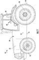
- FIG. 1 illustrates a side view of one embodiment of a work vehicle 10.
- the work vehicle 10 is configured as an agricultural tractor.
- the work vehicle 10 may be configured as any other suitable work vehicle known in the art, such as various other agricultural vehicles, earth-moving vehicles, road vehicles, all-terrain vehicles, off-road vehicles, loaders and/or the like.
- the work vehicle 10 includes a pair of front wheels 12, a pair or rear wheels 14 and a chassis 16 coupled to and supported by the wheels 12, 14.
- An operator's cab 18 may be supported by a portion of the chassis 16 and may house various control devices 20 (e.g., levers, pedals, control panels and/or the like) for permitting an operator to control the operation of the work vehicle 10.
- the work vehicle 10 may include an engine 22 and a transmission 24 mounted on the chassis 16.
- the transmission 24 may be operably coupled to the engine 22 and may provide variably adjusted gear ratios for transferring engine power to the wheels 14 via a differential 26.
- the engine 22, transmission 24, and differential 26 may collectively define a drive train 28 of the work vehicle 10.
- the configuration of the work vehicle 10 described above and shown in FIG. 1 is provided only to place the present subject matter in an exemplary field of use.
- the present subject matter may be readily adaptable to any manner of work vehicle configuration.
- a separate frame or chassis may be provided to which the engine 22, transmission 24, and differential are coupled, a configuration common in smaller tractors.
- Still other configurations may use an articulated chassis to steer the work vehicle 10, or rely on tracks in lieu of tires.
- FIGS. 2-4 differing views of one embodiment an air intake system 100 suitable for use with the work vehicle 10 shown in FIG. 1 are illustrated in accordance with aspects of the present subject matter.
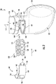
- FIG. 2 illustrates a perspective view of the air intake system 100.
- FIG. 3 illustrates a partial perspective view of the air intake system 100 shown in FIG. 2 , particularly illustrating an exploded view of various components of the system 100.
- FIG. 4 illustrates a cross-sectional view of the air intake system 100 shown in FIG. 2 taken about line 4-4.
- the air intake system 100 may generally include an intake duct 102 and a filter assembly 104 configured to be housed within a portion of the intake duct 102.
- the intake duct 102 may generally be configured to receive dirty air flowing outside the work vehicle 10 and direct such air into the filter assembly 104 for cleaning/filtering before delivery to the engine 22.
- the intake duct 102 may generally correspond an elongated, conduit-like body including an outer surface 106 ( FIGS. 3 and 4 ) defining the outer circumference or perimeter of the duct 102 and an inner surface 108 ( FIG. 4 ) defining the inner circumference or perimeter of the duct 102.
- an internal passageway 110 FIGS.
- the intake duct 102 may include one or more inlet openings (not shown) for receiving air.
- a screen 114 may be disposed over the inlet openings, thereby preventing large debris from entering the intake duct 102. The air flowing through the screen 114 and into the intake duct 102 may then be directed in the flow direction 112 along the internal passageway 110 and through the filter assembly 104 prior to being delivered to the engine 22.
- the intake duct 102 may, in several embodiments, include an upper portion 116 for receiving air and a lower portion 118 configured to house the various components of the filter assembly 104.
- the upper and lower portions 116, 118 may, for example, correspond to separate components configured to be coupled to one another to form the complete intake duct 102.
- the upper and lower portions 116, 118 may be formed integrally with one another.
- the filter assembly 104 of the air intake system 100 may generally be configured to receive the dirty air flowing through the intake duct 102 and clean/filter such air for subsequent delivery to the engine 22.
- the filter assembly 104 may include a pre-cleaner 120 and an air filter 122 disposed downstream of the pre-cleaner 120.
- the pre-cleaner 120 may be configured to remove large sized debris or particulates contained within the air flowing into the filter assembly 104 via the intake duct 102.
- the pre-cleaner 120 may include an upper wall 124, a lower wall 126 and a plurality of pre-cleaner elements 128 extending between the upper and lower walls 124, 126.
- the pre-cleaner elements 128 may correspond to tubes (e.g., turbo tubes), dirt separators, and/or any other suitable elements configured to separate particulates from the air via centrifugal force.
- the pre-cleaner elements 128 may be configured to impart a vortex or spinning motion to the flow of air entering the filter assembly 104.
- large particulates contained within the air may be forced radially outwardly along the inner surface 108 of the duct 102 by the centrifugal force of the vortex/spinning motion. These large particulates may then be expelled from the intake duct 102 via an outlet port (not shown) defined through a portion of the duct 102.
- the air filter 122 may generally be configured to receive the cleaned air flowing from the pre-cleaner 120 and filter such air to provide a final stage of filtering prior to delivery of the air to the engine 22.
- the air filter 122 may generally include one or more filter elements 130 configured to catch or trap the remaining particulates contained within the cleaned air.
- the filter element(s) 130 may be made from a fibrous, porous or mesh material that allows air to pass therethrough while catching/trapping any particulates. The cleaned/filtered air may then be directed through a suitable conduit (not shown) to the engine 22, where the air may be mixed with fuel and combusted.
- the intake duct 102 may define a pre-cleaner slot 140 configured to allow the pre-cleaner 120 to be quickly and easily installed within and removed from the intake duct 102.
- the pre-cleaner 120 may be configured to be installed within (or removed from) the intake duct 102 by inserting the pre-cleaner 120 into the slot 140 (or by pulling the pre-cleaner 120 out of the slot 140) in a lateral direction (indicated by arrow 142 in FIGS. 3 and 4 ) extending generally perpendicular to the flow direction 112 of the air through the intake duct 102.
- a lateral direction indicated by arrow 142 in FIGS. 3 and 4
- a cover 144 may be configured to be removably coupled to the intake duct 102 such that the cover 144 extends over or otherwise covers the pre-cleaner slot 140 when the pre-cleaner 120 is installed within the intake duct 102.
- the cover 144 may be removed from the intake duct 102 and the pre-cleaner 120 may be pulled outwardly from the duct 102 via the pre-cleaner slot 140 (e.g., by pulling the pre-cleaner 120 in the lateral direction 142 relative to the duct 102).
- the pre-cleaner 120 may then be re-installed into the intake duct 102 by laterally inserting the pre-cleaner 120 through the pre-cleaner slot 140.
- the cover 144 may then be installed back on the intake duct 102 to close-off or otherwise cover the slot 140.
- the pre-cleaner slot 140 may be configured to extend through the intake duct 102 (e.g., by being defined between the outer and inner surfaces 106, 108 of the duct 102) such that the slot 140 provides access to the portion of the duct 102 within which the pre-cleaner 102 is configured to be installed. Additionally, as shown in FIG. 3 , the slot 140 may generally be configured to extend circumferentially around the intake duct 102 between a first slot end 146 and a second slot end 148 so as to define a sufficiently sized opening for receiving the pre-cleaner 120.
- the pre-cleaner slot 140 may generally be configured to extend around any suitable circumferential portion of the intake duct 102 that allows the pre-cleaner 120 to be inserted into and removed from the duct 102 via the slot 140.
- the pre-cleaner slot 140 may extend circumferentially between its first and second ends 146, 148 around an approximately 180 degree circumferential segment of the intake duct 102.
- the intake duct 102 may include a support ledge 150 extending around its inner perimeter at a location at or adjacent to the pre-cleaner slot 140.
- the support ledge 150 may be configured to extend radially inwardly relative to the remainder of the inner surface 108 of the intake duct 102 so as to define a circumferential lip or ledge for vertically supporting the pre-cleaner 120 within the intake duct 102.
- the lower wall 126 of the pre-cleaner 120 may be configured to be engaged against and/or positioned adjacent to the support ledge 150 when the pre-cleaner 120 is installed within the intake duct 102.
- the support ledge 150 may be configured to accommodate one or more seals for sealing the pre-cleaner 120 against the inner perimeter of the intake duct 102.
- a sealing member(s) 152 may be positioned on the support ledge 150 such that the sealing member 152 extends circumferentially along the ledge 150 around at least a portion of the inner perimeter of the intake duct 102.
- the sealing member(s) 152 may be configured to create a seal between the support ledge 150 and the lower wall 126 of the pre-cleaner 120.
- the sealing member 152 may be configured to provide a sealed interface between the intake duct 102 and the pre-cleaner 120 that prevents the flow of air between the outer perimeter of the pre-cleaner 120 and the inner perimeter of the intake duct 102.
- the sealing member(s) 152 may generally correspond to any suitable sealing device(s) or seal(s) known in the art.
- the sealing member(s) 152 may be formed from a compressible material that is configured to be compressed between the support ledge 150 and the lower wall 126 of the pre-cleaner 120 so as to form a seal between such adjacent components.
- the compressible material may include, but is not limited to, a rubber material, a foam material (e.g., an open- or closed-cell foam material) and/or any other suitable compressible material.
- the cover 144 may generally be shaped or otherwise configured based on the size and/or shape of the pre-cleaner slot 140 such that, when the cover 144 is coupled to the duct 102, the cover 144 extends across or otherwise covers the slot 140.
- the cover 144 may generally define an arced or curved shape extending circumferentially between a first cover end 154 and a second cover end 156.
- the curvature of the cover 144 may generally be configured to match the curvature of the intake duct 102.
- the first end 154 of the cover 144 may be positioned at or adjacent to the first end 146 of the pre-cleaner slot 140 while the second end 156 of the cover 144 may be positioned at or adjacent to the second end 148 of the pre-cleaner slot 140.
- the ends 154, 156 of the cover 144 may be configured to extend circumferentially beyond the ends 146, 148 of the slot 140 by a given distance such that the cover 144 overlaps portions of the outer surface 106 of the intake duct 102 extending adjacent to the ends 146, 148 of the slot 140.
- the ends 154, 156 of the cover 144 may be configured to be sealed against the intake duct 102 at or adjacent to the ends 146, 148 of the slot 140.
- the outer surface 106 of the intake duct 102 may be recessed at one or more locations adjacent to the pre-cleaner slot 140.
- the outer surface106 may be recessed along the top and bottom of the pre-cleaner slot 140 such that upper and lower recesses 158, 160 are defined by the outer surface 106 that extend circumferentially around the outer perimeter of the intake duct 102 between the first and second ends 146, 148 of the slot 140.
- corresponding upper and lower portions 162, 164 of the cover 144 may be configured to be at least partially received within the upper and lower recesses 158, 160, respectively. For instance, as shown in FIG.
- the upper portion 162 of the cover 144 may be received within the upper recess 158 and the lower portion 164 of the cover 144 may be received with the lower recess 160, thereby providing an overlapping configuration between the intake duct 102 and the cover 144 along the top and the bottom sides of the slot 140.
- one or more sealing members 166, 168 may be positioned within the recesses 158, 160 to provide a seal between the cover 144 and the intake duct 102.
- an upper sealing member 166 may be positioned within the upper recess 158 to provide a sealed interface between the intake duct 102 and the upper portion 162 of the cover 144.
- a lower sealing member 168 may be positioned within the lower recess 160 to provide a sealed interface between the intake duct 102 and the lower portion 164 of the cover 144.
- each sealing member 166, 168 may generally correspond to any suitable sealing device(s) or seal(s) known in the art.
- each sealing member 166, 168 may be formed from a compressible material that is configured to be compressed between the intake duct 102 and the cover 144 so as to form a seal between such adjacent components.
- the compressible material may include, but is not limited to, a rubber material, a foam material (e.g., an open- or closed-cell foam material) and/or any other suitable compressible material.
- the intake duct 102 and the cover 144 may include corresponding retention members for allowing the cover 144 to be removably coupled to the duct 102.
- the cover 144 may include one or more retention clips 170 extending outwardly from its first and second ends 154, 156.
- corresponding latches 172 or other retention members may be provided adjacent to the ends 146, 148 of the pre-cleaner slot 140 that are configured to engage the retention clips 170 when the cover 144 is installed onto the duct 102.
- each retention clip 170 may be configured to be received within a corresponding latch 172 in order to secure the cover 144 to the intake duct 102.
- the intake duct 102 and the cover 144 may include any other suitable retention members and/or features configured to allow the cover 144 to be removably coupled to the duct 102.
- the pre-cleaner 120 may include one or more tabs 174, 176 extending radially outwardly from its upper wall and/or its lower wall 124, 126.
- the pre-cleaner 120 includes a first tab 174 extending outwardly from the upper wall 124 and a second tab 176 extending outwardly from the lower wall 126.
- the tabs 174, 176 may be configured to be received within corresponding locating grooves 178, 180 defined along the inner perimeter of the intake duct 102.
- the tabs 174, 176 and corresponding grooves 178, 180 may allow the pre-cleaner 120 to be properly positioned within the intake duct 102 relative to the support ledge 150.
- the locating grooves 178, 180 may be configured to extend at least partially downward (e.g., in the flow direction 112) along the inner perimeter of the intake duct 102 such that, when each tab 174, 176 is received within its corresponding locating groove 178, 180 and the pre-cleaner 120 is rotated relative to the intake duct 102, the pre-cleaner 120 may be moved relative to the intake duct 102 in the flow direction 112, thereby ensuring that a sealed interface is created between the lower wall 126 of the pre-cleaner 120 and the support ledge 150.
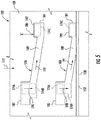
- FIG. 5 illustrates a front view of one embodiment of suitable locating grooves 178, 180 that may be defined along the inner perimeter of the intake duct 102 for receiving the pre-cleaner tabs 174, 176.
- the intake duct 102 includes first and second locating grooves 178, 180 defined by its inner surface 108, with the first locating groove 178 being configured to receive the first tab 174 of the pre-cleaner 120 and the second locating groove 180 being configured to receive the second tab 176 of the pre-cleaner 120.
- the locating grooves 178, 180 may be configured to define a circumferential travel path for the tabs 174, 176 along the inner perimeter of the intake duct 102 as the pre-cleaner 120 is being rotated relative to the duct 102.
- each locating groove 178, 180 may be configured to extend circumferentially along the inner perimeter of the duct 102 between a first end 182 and a second end 184.
- the second end 184 may be configured to be offset from the first end 182 in the flow direction 112 of the air intake system 100 (e.g., by an offset distance 186).
- each locating groove 178, 180 may include an angled portion 188 that is angled downwardly in the flow direction 112 as the angled portion 188 extends from the first end 182 to the second end 184 of the groove 178, 180.
- Such downward travel of the pre-cleaner 120 as the tabs 174, 176 are moved along the angled portions 188 may result in the sealing member 152 being compressed between the lower wall 126 of the pre-cleaner 120 and the support ledge 150, thereby providing an effective sealed interface between the pre-cleaner 120 and the intake duct 102.
- the tabs 174, 176 may be initially received at the open, first ends 182 of the locating grooves 178, 180. Thereafter, the pre-cleaner 120 may be pushed downwardly relative to the intake duct 102 (indicated by arrows 190) such that each tab 174, 176 is generally aligned within the angled portion 188 of its corresponding groove 178, 180 (as indicated by dashed boxes, 174B, 176B).
- the pre-cleaner 120 may then be rotated relative to the intake duct 102 such that the tabs 174, 176 travel along the angled portions 186 of the grooves 178, 180 (e.g., as indicated by arrows 191) in the direction of the second end 184 of each groove 178, 180. As indicated above, such movement of the pre-cleaner 120 may result in a downward force being applied against the sealing member 152 that compresses the sealing member 182 between the lower wall 126 of the pre-cleaner 120 and the support ledge 150.
- each locating groove 178, 180 may include a raised portion 192 at or adjacent to its second end 184 that extends upwardly relative to the angled portion 188.
- the pre-cleaner 120 may be allowed to spring slightly upwardly relative to the intake duct 102 (e.g., due to the reactive force provided by the compressed sealing member 152) such that the tabs 174, 176 are received within the raised portions 192 of the grooves 178, 180, thereby locking the tabs 174, 176 in place.
- the pre-cleaner 120 may be initially pushed downwardly relative to the duct 102 such that the tabs 174, 176 are moved out of the raised positions 192 and back into alignment with the angled portions 188 of the grooves 178, 180.
- the pre-cleaner 120 may then be rotated relative to the intake duct 102 to allow the tabs 174, 176 to travel upwardly along the angled portions 188 towards the first ends 182 of the grooves 178, 180.
- the locating grooves 178, 180 shown in FIG. 5 are simply provided as one example of suitable locating features that may be provided in association with the intake duct 102 for properly locating the pre-cleaner 120 within the duct 102.
- the intake duct 102 may include any other suitable locating features, including grooves defining any other suitable travel path for the pre-cleaner tabs 174, 176 along the inner perimeter of the intake duct 102.
- a handle 194 may also be provided on the pre-cleaner 120 to assist in the removal and installation of the pre-cleaner 120 relative to the intake duct 102.
- the handle 194 may be configured to extend radially outwardly from the upper and lower walls 124, 126 of the pre-cleaner 120 so as to provide sufficient spacing for allowing an operator of the vehicle or service personnel to grasp the handle 194.
- the handle 194 may extend outwardly from the upper and lower walls 124, 126 a given radial distance 195.
- the handle 194 may be used by the operator/service personal to push/pull the pre-cleaner 120 through the pre-cleaner slot 140 when inserting/removing the pre-cleaner 120 relative to the duct 102.
- the handle 194 may be used to rotate the pre-cleaner 120 relative to the intake duct 102 to adjust the position of the pre-cleaner tabs 174, 176 within the locating grooves 178, 180.
- the handle 194 may be used to rotate the pre-cleaner 120 in a first direction relative to the intake duct 102 to move each tab 174, 176 from the first end 182 to the second end 184 of its corresponding locating groove 178, 180.
- the handle 194 may be used to rotate the pre-cleaner 120 in the opposite direction relative to the intake duct 102 to move each tab 174, 176 from the second end 184 to the first end 182 of its corresponding locating groove 178, 180.
- a handle portion 196 of the cover 144 may be configured to project outwardly relative to the remainder of the cover 144 so as to define a cavity 198 ( FIG. 4 ) for receiving the handle 194 of the pre-cleaner 120.
- the handle 194 may be received within the cavity 198 defined by the handle portion 196 of the cover 144.
- the handle portion 196 may generally be configured to extend out-of-profile relative to the remainder of the cover 144 any suitable radial distance that allows the handle 194 to be received within the cavity 198 when the cover 144 is installed onto the intake duct 102.
Landscapes
- Engineering & Computer Science (AREA)
- Chemical & Material Sciences (AREA)
- Combustion & Propulsion (AREA)
- Mechanical Engineering (AREA)
- General Engineering & Computer Science (AREA)
- Chemical Kinetics & Catalysis (AREA)
- Manufacturing & Machinery (AREA)
- Filtering Of Dispersed Particles In Gases (AREA)
- Cooling, Air Intake And Gas Exhaust, And Fuel Tank Arrangements In Propulsion Units (AREA)
- Filling Or Discharging Of Gas Storage Vessels (AREA)
Abstract
Description
- The present subject matter relates generally to work vehicle and, more particularly, to an air intake system for a work vehicle that provides for enhanced serviceability of the system's pre-cleaner.
- Work vehicles typically include internal combustion engines that require clean air for use within the combustion process. Since many work vehicles, such as tractors and other agricultural vehicles, operate in fields and other harvesting environments in which the ambient air contains large amounts of dust, plant material and other particulates, an air intake system having an effective filter assembly is required. For example, conventional filter assemblies for work vehicles typically include a vortex or cyclone pre-cleaner configured to separate large particulates from the intake air and a porous air filter downstream of the pre-cleaner to provide the final stage of filtering prior to delivering the air into the engine.
- To prevent the air filter from clogging, the large particulates separated from the intake air by the pre-cleaner must be removed from the filter assembly. Typically, such particulates are removed from the filter assembly via an outlet duct using a vacuum generated by the exhaust flow from the engine or using the vehicle's cooling fan. However, even with the use of such exhaust-driven or fan-driven aspiration systems, the pre-cleaner may become clogged with large particulates. In such instances, it may be desirable to remove the pre-cleaner from the intake duct of the air intake system to allow the pre-cleaner to be cleaned or unclogged. Currently, to service the pre-cleaner, an operator must remove a portion of the intake duct and then reach downwardly into the remaining portion of the duct in an attempt to vertically dislodge or un-wedge the pre-cleaner from the duct. Given this difficult process, operators often neglect servicing the pre-cleaner, which can lead to a decreased overall component life of the filter assembly.
- Accordingly, an improved air intake system that allows for the pre-cleaner to be quickly and easily serviced would be welcomed in the technology.
- Aspects and advantages of the invention will be set forth in part in the following description, or may be obvious from the description, or may be learned through practice of the invention.
- In one aspect, the present subject matter is directed to an air intake system for a work vehicle. The air intake system may generally include an intake duct having an inner surface and an outer surface. The inner surface may define a passageway for directing air in a flow direction through the air intake system. The intake duct may also include a pre-cleaner slot defined between the inner and outer surfaces and a support ledge extending circumferentially around at least a portion of an inner perimeter of the intake duct. The air intake system may also include a pre-cleaner having an upper wall, a lower wall and a plurality of pre-cleaner elements extending between the upper and lower walls. The pre-cleaner may be configured to be installed within the intake duct by inserting the pre-cleaner through the pre-cleaner slot in a direction extending generally perpendicular to the flow direction. In addition, the air intake system may include a cover configured to be coupled to the intake duct such that the cover extends over the pre-cleaner slot when the pre-cleaner is installed within the intake duct. Moreover, when the pre-cleaner is installed within the intake duct, at least a portion of the lower wall may be sealed against the support ledge.
- In another aspect, the present subject matter is directed to an air intake system for a work vehicle. The air intake system may generally include an intake duct having an inner surface and an outer surface. The inner surface may define a passageway for directing air in a flow direction through the air intake system. The inner surface may further define at least one locating groove extending along an inner perimeter of the intake duct. The intake duct may also include a pre-cleaner slot defined between the inner and outer surfaces and a support ledge extending circumferentially around at least a portion of the inner perimeter of the intake duct. The air intake system may also include a sealing member positioned on the support ledge and a pre-cleaner having an upper wall, a lower wall and a plurality of pre-cleaner elements extending between the upper and lower walls. The pre-cleaner may also include at least one tab extending outwardly from at least one of the upper wall or the lower wall. The pre-cleaner may be configured to be installed within the intake duct by inserting the pre-cleaner through the pre-cleaner slot. In addition, when the pre-cleaner is installed within the intake duct such that the tab(s) of the pre-cleaner is received within the locating groove(s) of the intake duct, the sealing member is configured to provide a sealed interface between at least a portion of the lower wall of the pre-cleaner and the support ledge of the intake duct.
- In a further aspect, the present subject matter is directed to an air intake system for a work vehicle. The air intake system may generally include an intake duct having an inner surface and an outer surface. The inner surface may define a passageway for directing air in a flow direction through the air intake system. The intake duct may also include a pre-cleaner slot defined between the inner and outer surfaces. The air intake system may also include a pre-cleaner having an upper wall, a lower wall and a plurality of pre-cleaner elements extending between the upper and lower walls. The pre-cleaner may also include a handle extending outwardly from at least one of the upper wall or the lower wall. The pre-cleaner may be configured to be installed within the intake duct by inserting the pre-cleaner through the pre-cleaner slot in a direction extending generally perpendicular to the flow direction. In addition, the air intake system may include a cover configured to be coupled to the intake duct such that the cover extends over the pre-cleaner slot when the pre-cleaner is installed within the intake duct. The cover may define a cavity configured to receive the handle when the cover is positioned over the pre-cleaner slot.
- These and other features, aspects and advantages of the present invention will become better understood with reference to the following description and appended claims. The accompanying drawings, which are incorporated in and constitute a part of this specification, illustrate embodiments of the invention and, together with the description, serve to explain the principles of the invention.
- A full and enabling disclosure of the present invention, including the best mode thereof, directed to one of ordinary skill in the art, is set forth in the specification, which makes reference to the appended figures, in which:
-
FIG. 1 illustrates a side view of one embodiment of a work vehicle; -
FIG. 2 illustrates a perspective view of one embodiment of an air intake system suitable for use with the work vehicle shown inFIG. 1 in accordance with aspects of the present subject matter; -
FIG. 3 illustrates a partial perspective view of the air intake system shown inFIG. 2 , particularly illustrating a cover and a pre-cleaner of the air intake system exploded away from an intake duct of the system; -
FIG. 4 illustrates a cross-sectional view of a portion of the air intake system shown inFIG. 2 taken about line 4-4; and -
FIG. 5 illustrates an internal view of a portion of the intake duct shown inFIGS. 2-4 , particularly illustrating one example of locating grooves that may be defined along an inner perimeter of the duct for locating the pre-cleaner relative to the duct. - Reference now will be made in detail to embodiments of the invention, one or more examples of which are illustrated in the drawings. Each example is provided by way of explanation of the invention, not limitation of the invention. In fact, it will be apparent to those skilled in the art that various modifications and variations can be made in the present invention without departing from the scope or spirit of the invention. For instance, features illustrated or described as part of one embodiment can be used with another embodiment to yield a still further embodiment. Thus, it is intended that the present invention covers such modifications and variations as come within the scope of the appended claims and their equivalents.
- In general, the present subject matter is directed to an improved air intake system that provides for enhanced pre-cleaner serviceability. Specifically, in several embodiments, the air intake system may include an intake duct defining an opening or slot for receiving a pre-cleaner of the system. The slot may generally be defined through the side of the intake duct such that the pre-cleaner may be easily inserted into and removed from the intake duct (e.g., in a lateral direction perpendicular to the direction of flow through the duct) . In addition, the air intake system may include a service cover configured to be removably coupled to the intake duct so as to cover or otherwise extend over the slot when the pre-cleaner is installed within the intake duct. As such, when it is desired to service the pre-cleaner, the cover may be decoupled from the intake duct to allow the pre-cleaner to be removed laterally from the intake duct via the slot. After cleaning or otherwise servicing the pre-cleaner, the pre-cleaner may be re-installed within the intake duct by inserting the pre-cleaner back through the slot. The cover may then be re-installed onto the intake duct to complete the servicing.
- Referring now to the drawings,
FIG. 1 illustrates a side view of one embodiment of awork vehicle 10. As shown, thework vehicle 10 is configured as an agricultural tractor. However, in other embodiments, thework vehicle 10 may be configured as any other suitable work vehicle known in the art, such as various other agricultural vehicles, earth-moving vehicles, road vehicles, all-terrain vehicles, off-road vehicles, loaders and/or the like. - As shown in
FIG. 1 , thework vehicle 10 includes a pair offront wheels 12, a pair orrear wheels 14 and achassis 16 coupled to and supported by thewheels cab 18 may be supported by a portion of thechassis 16 and may house various control devices 20 (e.g., levers, pedals, control panels and/or the like) for permitting an operator to control the operation of thework vehicle 10. Additionally, thework vehicle 10 may include anengine 22 and atransmission 24 mounted on thechassis 16. Thetransmission 24 may be operably coupled to theengine 22 and may provide variably adjusted gear ratios for transferring engine power to thewheels 14 via a differential 26. Theengine 22,transmission 24, and differential 26 may collectively define adrive train 28 of thework vehicle 10. - It should be appreciated that the configuration of the
work vehicle 10 described above and shown inFIG. 1 is provided only to place the present subject matter in an exemplary field of use. Thus, it should be appreciated that the present subject matter may be readily adaptable to any manner of work vehicle configuration. For example, in an alternative embodiment, a separate frame or chassis may be provided to which theengine 22,transmission 24, and differential are coupled, a configuration common in smaller tractors. Still other configurations may use an articulated chassis to steer thework vehicle 10, or rely on tracks in lieu of tires. - Referring now to
FIGS. 2-4 , differing views of one embodiment anair intake system 100 suitable for use with thework vehicle 10 shown inFIG. 1 are illustrated in accordance with aspects of the present subject matter. Specifically,FIG. 2 illustrates a perspective view of theair intake system 100.FIG. 3 illustrates a partial perspective view of theair intake system 100 shown inFIG. 2 , particularly illustrating an exploded view of various components of thesystem 100. Additionally,FIG. 4 illustrates a cross-sectional view of theair intake system 100 shown inFIG. 2 taken about line 4-4. - As shown, the
air intake system 100 may generally include anintake duct 102 and afilter assembly 104 configured to be housed within a portion of theintake duct 102. Theintake duct 102 may generally be configured to receive dirty air flowing outside thework vehicle 10 and direct such air into thefilter assembly 104 for cleaning/filtering before delivery to theengine 22. Thus, in several embodiments, theintake duct 102 may generally correspond an elongated, conduit-like body including an outer surface 106 (FIGS. 3 and4 ) defining the outer circumference or perimeter of theduct 102 and an inner surface 108 (FIG. 4 ) defining the inner circumference or perimeter of theduct 102. As is generally, understood, an internal passageway 110 (FIGS. 3 and4 ) may be defined by theinner surface 108 of theintake duct 102 for directing air in a flow direction (indicated byarrows 112 inFIGS, 2-4 ) along thepassageway 110 and through thefilter assembly 104. For example, theintake duct 102 may include one or more inlet openings (not shown) for receiving air. As shown inFIG. 2 , ascreen 114 may be disposed over the inlet openings, thereby preventing large debris from entering theintake duct 102. The air flowing through thescreen 114 and into theintake duct 102 may then be directed in theflow direction 112 along theinternal passageway 110 and through thefilter assembly 104 prior to being delivered to theengine 22. - As particularly shown in
FIG. 2 , theintake duct 102 may, in several embodiments, include anupper portion 116 for receiving air and alower portion 118 configured to house the various components of thefilter assembly 104. In one embodiment, the upper andlower portions complete intake duct 102. Alternatively, the upper andlower portions - As indicated above, the
filter assembly 104 of theair intake system 100 may generally be configured to receive the dirty air flowing through theintake duct 102 and clean/filter such air for subsequent delivery to theengine 22. Thus, in several embodiments, thefilter assembly 104 may include a pre-cleaner 120 and anair filter 122 disposed downstream of the pre-cleaner 120. As is generally understood, the pre-cleaner 120 may be configured to remove large sized debris or particulates contained within the air flowing into thefilter assembly 104 via theintake duct 102. As particularly shown inFIGS. 3 and4 , the pre-cleaner 120 may include anupper wall 124, alower wall 126 and a plurality ofpre-cleaner elements 128 extending between the upper andlower walls pre-cleaner elements 128 may correspond to tubes (e.g., turbo tubes), dirt separators, and/or any other suitable elements configured to separate particulates from the air via centrifugal force. For example, thepre-cleaner elements 128 may be configured to impart a vortex or spinning motion to the flow of air entering thefilter assembly 104. As a result, large particulates contained within the air may be forced radially outwardly along theinner surface 108 of theduct 102 by the centrifugal force of the vortex/spinning motion. These large particulates may then be expelled from theintake duct 102 via an outlet port (not shown) defined through a portion of theduct 102. - Additionally, the
air filter 122 may generally be configured to receive the cleaned air flowing from the pre-cleaner 120 and filter such air to provide a final stage of filtering prior to delivery of the air to theengine 22. Thus, as shown inFIG. 3 , theair filter 122 may generally include one ormore filter elements 130 configured to catch or trap the remaining particulates contained within the cleaned air. For instance, in several embodiments, the filter element(s) 130 may be made from a fibrous, porous or mesh material that allows air to pass therethrough while catching/trapping any particulates. The cleaned/filtered air may then be directed through a suitable conduit (not shown) to theengine 22, where the air may be mixed with fuel and combusted. - As particularly shown in
FIG. 3 , in accordance with aspects of the present subject matter, theintake duct 102 may define apre-cleaner slot 140 configured to allow the pre-cleaner 120 to be quickly and easily installed within and removed from theintake duct 102. Specifically, in several embodiments, the pre-cleaner 120 may be configured to be installed within (or removed from) theintake duct 102 by inserting the pre-cleaner 120 into the slot 140 (or by pulling the pre-cleaner 120 out of the slot 140) in a lateral direction (indicated byarrow 142 inFIGS. 3 and4 ) extending generally perpendicular to theflow direction 112 of the air through theintake duct 102. Additionally, as shown inFIGS. 2-4 , acover 144 may be configured to be removably coupled to theintake duct 102 such that thecover 144 extends over or otherwise covers thepre-cleaner slot 140 when the pre-cleaner 120 is installed within theintake duct 102. As such, to service the pre-cleaner 120, thecover 144 may be removed from theintake duct 102 and the pre-cleaner 120 may be pulled outwardly from theduct 102 via the pre-cleaner slot 140 (e.g., by pulling the pre-cleaner 120 in thelateral direction 142 relative to the duct 102). After cleaning or otherwise servicing the pre-cleaner 120, the pre-cleaner 120 may then be re-installed into theintake duct 102 by laterally inserting the pre-cleaner 120 through thepre-cleaner slot 140. Thecover 144 may then be installed back on theintake duct 102 to close-off or otherwise cover theslot 140. - As particularly shown in
FIGS. 3 and4 , thepre-cleaner slot 140 may be configured to extend through the intake duct 102 (e.g., by being defined between the outer andinner surfaces slot 140 provides access to the portion of theduct 102 within which the pre-cleaner 102 is configured to be installed. Additionally, as shown inFIG. 3 , theslot 140 may generally be configured to extend circumferentially around theintake duct 102 between a first slot end 146 and asecond slot end 148 so as to define a sufficiently sized opening for receiving the pre-cleaner 120. It should be appreciated that thepre-cleaner slot 140 may generally be configured to extend around any suitable circumferential portion of theintake duct 102 that allows the pre-cleaner 120 to be inserted into and removed from theduct 102 via theslot 140. For example, in one embodiment, thepre-cleaner slot 140 may extend circumferentially between its first and second ends 146, 148 around an approximately 180 degree circumferential segment of theintake duct 102. - Moreover, as shown in
FIGS. 3 and4 , theintake duct 102 may include asupport ledge 150 extending around its inner perimeter at a location at or adjacent to thepre-cleaner slot 140. In several embodiments, thesupport ledge 150 may be configured to extend radially inwardly relative to the remainder of theinner surface 108 of theintake duct 102 so as to define a circumferential lip or ledge for vertically supporting the pre-cleaner 120 within theintake duct 102. For example, thelower wall 126 of the pre-cleaner 120 may be configured to be engaged against and/or positioned adjacent to thesupport ledge 150 when the pre-cleaner 120 is installed within theintake duct 102. - In addition, the
support ledge 150 may be configured to accommodate one or more seals for sealing the pre-cleaner 120 against the inner perimeter of theintake duct 102. For example, as particularly shown inFIG. 4 , a sealing member(s) 152 may be positioned on thesupport ledge 150 such that the sealingmember 152 extends circumferentially along theledge 150 around at least a portion of the inner perimeter of theintake duct 102. In general, the sealing member(s) 152 may be configured to create a seal between thesupport ledge 150 and thelower wall 126 of the pre-cleaner 120. As such, when the pre-cleaner 120 is installed within theintake duct 102 via thepre-cleaner slot 140, the sealingmember 152 may be configured to provide a sealed interface between theintake duct 102 and the pre-cleaner 120 that prevents the flow of air between the outer perimeter of the pre-cleaner 120 and the inner perimeter of theintake duct 102. - It should be appreciated that the sealing member(s) 152 may generally correspond to any suitable sealing device(s) or seal(s) known in the art. For example, in several embodiments, the sealing member(s) 152 may be formed from a compressible material that is configured to be compressed between the
support ledge 150 and thelower wall 126 of the pre-cleaner 120 so as to form a seal between such adjacent components. In such embodiments, the compressible material may include, but is not limited to, a rubber material, a foam material (e.g., an open- or closed-cell foam material) and/or any other suitable compressible material. - As shown in
FIGS. 2 and3 , thecover 144 may generally be shaped or otherwise configured based on the size and/or shape of thepre-cleaner slot 140 such that, when thecover 144 is coupled to theduct 102, thecover 144 extends across or otherwise covers theslot 140. Specifically, as shown inFIG. 3 , thecover 144 may generally define an arced or curved shape extending circumferentially between afirst cover end 154 and asecond cover end 156. In such an embodiment, the curvature of thecover 144 may generally be configured to match the curvature of theintake duct 102. As such, when thecover 144 is installed onto theduct 102, thefirst end 154 of thecover 144 may be positioned at or adjacent to the first end 146 of thepre-cleaner slot 140 while thesecond end 156 of thecover 144 may be positioned at or adjacent to thesecond end 148 of thepre-cleaner slot 140. For example, in one embodiment, theends cover 144 may be configured to extend circumferentially beyond theends 146, 148 of theslot 140 by a given distance such that thecover 144 overlaps portions of theouter surface 106 of theintake duct 102 extending adjacent to theends 146, 148 of theslot 140. In addition to such an overlapped configuration (or as an alternative thereto), theends cover 144 may be configured to be sealed against theintake duct 102 at or adjacent to theends 146, 148 of theslot 140. - In one embodiment, the
outer surface 106 of theintake duct 102 may be recessed at one or more locations adjacent to thepre-cleaner slot 140. For example, as shown inFIGS. 3 and4 , the outer surface106 may be recessed along the top and bottom of thepre-cleaner slot 140 such that upper andlower recesses outer surface 106 that extend circumferentially around the outer perimeter of theintake duct 102 between the first and second ends 146, 148 of theslot 140. In such an embodiment, corresponding upper andlower portions cover 144 may be configured to be at least partially received within the upper andlower recesses FIG. 4 , when thecover 144 is installed onto theintake duct 102, theupper portion 162 of thecover 144 may be received within theupper recess 158 and thelower portion 164 of thecover 144 may be received with thelower recess 160, thereby providing an overlapping configuration between theintake duct 102 and thecover 144 along the top and the bottom sides of theslot 140. - Moreover, one or
more sealing members recesses cover 144 and theintake duct 102. For instance, as shown inFIG. 4 , anupper sealing member 166 may be positioned within theupper recess 158 to provide a sealed interface between theintake duct 102 and theupper portion 162 of thecover 144. Similarly, alower sealing member 168 may be positioned within thelower recess 160 to provide a sealed interface between theintake duct 102 and thelower portion 164 of thecover 144. - It should be appreciated that, similar to the sealing
member 152 described above, the upper andlower sealing members member intake duct 102 and thecover 144 so as to form a seal between such adjacent components. In such embodiments, the compressible material may include, but is not limited to, a rubber material, a foam material (e.g., an open- or closed-cell foam material) and/or any other suitable compressible material. - Moreover, in several embodiments, the
intake duct 102 and thecover 144 may include corresponding retention members for allowing thecover 144 to be removably coupled to theduct 102. For example, as shown inFIGS. 2 and3 , in one embodiment, thecover 144 may include one ormore retention clips 170 extending outwardly from its first and second ends 154, 156. In such an embodiment, correspondinglatches 172 or other retention members may be provided adjacent to theends 146, 148 of thepre-cleaner slot 140 that are configured to engage the retention clips 170 when thecover 144 is installed onto theduct 102. For example, eachretention clip 170 may be configured to be received within acorresponding latch 172 in order to secure thecover 144 to theintake duct 102. It should be appreciated that, in other embodiments, theintake duct 102 and thecover 144 may include any other suitable retention members and/or features configured to allow thecover 144 to be removably coupled to theduct 102. - Additionally, as shown in
FIGS. 3 and4 , in one embodiment, the pre-cleaner 120 may include one ormore tabs lower wall first tab 174 extending outwardly from theupper wall 124 and asecond tab 176 extending outwardly from thelower wall 126. As particularly shown inFIG. 4 , thetabs grooves intake duct 102. In general, thetabs corresponding grooves intake duct 102 relative to thesupport ledge 150. For example, in several embodiments, the locatinggrooves intake duct 102 such that, when eachtab groove intake duct 102, the pre-cleaner 120 may be moved relative to theintake duct 102 in theflow direction 112, thereby ensuring that a sealed interface is created between thelower wall 126 of the pre-cleaner 120 and thesupport ledge 150. - For example,
FIG. 5 illustrates a front view of one embodiment of suitable locatinggrooves intake duct 102 for receiving thepre-cleaner tabs intake duct 102 includes first and second locatinggrooves inner surface 108, with thefirst locating groove 178 being configured to receive thefirst tab 174 of the pre-cleaner 120 and thesecond locating groove 180 being configured to receive thesecond tab 176 of the pre-cleaner 120. In several embodiments, the locatinggrooves tabs intake duct 102 as the pre-cleaner 120 is being rotated relative to theduct 102. For example, as shown inFIG. 5 , each locatinggroove duct 102 between afirst end 182 and asecond end 184. In such an embodiment, thesecond end 184 may be configured to be offset from thefirst end 182 in theflow direction 112 of the air intake system 100 (e.g., by an offset distance 186). As such, the pre-cleaner 120 may be forced downwardly in the direction of thesupport ledge 150 as thetabs first end 182 to thesecond end 184 of eachgroove duct 102. For instance, as shown inFIG. 5 , each locatinggroove angled portion 188 that is angled downwardly in theflow direction 112 as theangled portion 188 extends from thefirst end 182 to thesecond end 184 of thegroove tabs angled portions 188 may result in the sealingmember 152 being compressed between thelower wall 126 of the pre-cleaner 120 and thesupport ledge 150, thereby providing an effective sealed interface between the pre-cleaner 120 and theintake duct 102. - As indicated by dashed
boxes FIG. 5 , when the pre-cleaner 120 is inserted within theintake duct 102 via thepre-cleaner slot 140, thetabs grooves tab angled portion 188 of itscorresponding groove 178, 180 (as indicated by dashed boxes, 174B, 176B). The pre-cleaner 120 may then be rotated relative to theintake duct 102 such that thetabs angled portions 186 of thegrooves 178, 180 (e.g., as indicated by arrows 191) in the direction of thesecond end 184 of eachgroove member 152 that compresses the sealingmember 182 between thelower wall 126 of the pre-cleaner 120 and thesupport ledge 150. - Additionally, as shown in
FIG. 5 , each locatinggroove portion 192 at or adjacent to itssecond end 184 that extends upwardly relative to theangled portion 188. As such, when thetabs grooves tabs portions 192 of thegrooves tabs intake duct 120, the pre-cleaner 120 may be initially pushed downwardly relative to theduct 102 such that thetabs positions 192 and back into alignment with theangled portions 188 of thegrooves intake duct 102 to allow thetabs angled portions 188 towards the first ends 182 of thegrooves - It should be appreciated that the locating
grooves FIG. 5 are simply provided as one example of suitable locating features that may be provided in association with theintake duct 102 for properly locating the pre-cleaner 120 within theduct 102. In other embodiments, theintake duct 102 may include any other suitable locating features, including grooves defining any other suitable travel path for thepre-cleaner tabs intake duct 102. - Referring back to
FIGS. 2-4 , ahandle 194 may also be provided on the pre-cleaner 120 to assist in the removal and installation of the pre-cleaner 120 relative to theintake duct 102. For example, thehandle 194 may be configured to extend radially outwardly from the upper andlower walls handle 194. Specifically, as shown inFIG. 4 , thehandle 194 may extend outwardly from the upper andlower walls 124, 126 a givenradial distance 195. As such, thehandle 194 may be used by the operator/service personal to push/pull the pre-cleaner 120 through thepre-cleaner slot 140 when inserting/removing the pre-cleaner 120 relative to theduct 102. In addition, thehandle 194 may be used to rotate the pre-cleaner 120 relative to theintake duct 102 to adjust the position of thepre-cleaner tabs grooves handle 194 may be used to rotate the pre-cleaner 120 in a first direction relative to theintake duct 102 to move eachtab first end 182 to thesecond end 184 of itscorresponding locating groove handle 194 may be used to rotate the pre-cleaner 120 in the opposite direction relative to theintake duct 102 to move eachtab second end 184 to thefirst end 182 of itscorresponding locating groove - Additionally, as shown in the illustrated embodiment, a
handle portion 196 of thecover 144 may be configured to project outwardly relative to the remainder of thecover 144 so as to define a cavity 198 (FIG. 4 ) for receiving thehandle 194 of the pre-cleaner 120. In such an embodiment, as shown inFIG. 4 , when thecover 144 is installed onto theintake duct 102 over thepre-cleaner slot 140, thehandle 194 may be received within thecavity 198 defined by thehandle portion 196 of thecover 144. It should be appreciated that thehandle portion 196 may generally be configured to extend out-of-profile relative to the remainder of thecover 144 any suitable radial distance that allows thehandle 194 to be received within thecavity 198 when thecover 144 is installed onto theintake duct 102. - This written description uses examples to disclose the invention, including the best mode, and also to enable any person skilled in the art to practice the invention, including making and using any devices or systems and performing any incorporated methods. The patentable scope of the invention is defined by the claims, and may include other examples that occur to those skilled in the art. Such other examples are intended to be within the scope of the claims if they include structural elements that do not differ from the literal language of the claims, or if they include equivalent structural elements with insubstantial differences from the literal languages of the claims.
Claims (10)
- An air intake system for a work vehicle, the air intake system comprising:an intake duct including an inner surface and an outer surface, the inner surface defining a passageway for directing air in a flow direction through the air intake system, the intake duct including a pre-cleaner slot defined between the inner and outer surfaces, the intake duct further including a support ledge extending circumferentially around at least a portion of an inner perimeter of the intake duct;a pre-cleaner including an upper wall, a lower wall and a plurality of pre-cleaner elements extending between the upper and lower walls, the pre-cleaner configured to be installed within the intake duct by inserting the pre-cleaner through the pre-cleaner slot in a direction extending generally perpendicular to the flow direction; anda cover configured to be coupled to the intake duct such that the cover extends over the pre-cleaner slot when the pre-cleaner is installed within the intake duct,wherein, when the pre-cleaner is installed within the intake duct, at least a portion of the lower wall is sealed against the support ledge.
- The air intake system of claim 1, further comprising a sealing member positioned on the support ledge, the sealing member configured to provide a sealed interface between the at least a portion of the lower wall and the support ledge.
- The air intake system of claim 2, wherein the sealing member is formed from a compressible material, wherein the compressible material is compressed between the lower wall and the support ledge when the pre-cleaner is installed within the intake duct.
- The air intake system of claim 1, wherein the pre-cleaner includes at least one tab extending outwardly from at least one of the lower wall or the upper wall, wherein the at least one tab is configured to be received within at least one locating groove defined along the inner perimeter of the intake duct.
- The air intake system of claim 4, wherein the at least one locating groove extends circumferentially along the inner perimeter of the intake duct between a first end and a second end, the second end being offset from the first end in the flow direction of the intake duct.
- The air intake system of claim 5, wherein, when the at least one tab is received within the at least one locating groove, the pre-cleaner is configured to be rotated relative to the intake duct such that the at least one tab is moved between the first and second ends of the at least one locating groove.
- The air intake system of claim 1, wherein the outer surface of the intake duct defines a recess adjacent to the pre-cleaner slot and wherein a portion of the cover is configured to be received within the recess when the cover is coupled to the intake duct.
- The air intake system of claim 7, further comprising a sealing member positioned within the recess so as to provide a sealed interface between the cover and the intake duct.
- The air intake system of claim 1, wherein the pre-cleaner includes a handle extending outwardly relative to at least one of the upper wall or the lower wall, the cover defining a cavity configured to receive the handle when the cover is installed over the pre-cleaner slot.
- The air intake system of claim 1, wherein the intake duct includes at least one retention member positioned adjacent to the pre-cleaner slot, the at least one retention member configured to engage at least one corresponding retention member of the cover when the cover is installed over the pre-cleaner slot.
Applications Claiming Priority (1)
| Application Number | Priority Date | Filing Date | Title |
|---|---|---|---|
| US14/945,718 US9909543B2 (en) | 2015-11-19 | 2015-11-19 | Air intake system for a work vehicle with enhanced pre-cleaner serviceability |
Publications (3)
| Publication Number | Publication Date |
|---|---|
| EP3171012A2 true EP3171012A2 (en) | 2017-05-24 |
| EP3171012A3 EP3171012A3 (en) | 2017-06-21 |
| EP3171012B1 EP3171012B1 (en) | 2018-09-19 |
Family
ID=57354223
Family Applications (1)
| Application Number | Title | Priority Date | Filing Date |
|---|---|---|---|
| EP16199597.2A Active EP3171012B1 (en) | 2015-11-19 | 2016-11-18 | Air intake system for a work vehicle with enhanced pre-cleaner serviceability |
Country Status (4)
| Country | Link |
|---|---|
| US (1) | US9909543B2 (en) |
| EP (1) | EP3171012B1 (en) |
| CN (1) | CN206221110U (en) |
| BR (1) | BR102016026867B1 (en) |
Families Citing this family (8)
| Publication number | Priority date | Publication date | Assignee | Title |
|---|---|---|---|---|
| US10131222B1 (en) * | 2017-05-05 | 2018-11-20 | Toyota Motor Engineering & Manufacturing North America, Inc. | Snorkel roof drip attachment |
| US11319907B2 (en) | 2018-02-14 | 2022-05-03 | Toyota Boshoku Kabushiki Kaisha | Precleaner for internal combustion engine |
| JP6996409B2 (en) * | 2018-02-14 | 2022-01-17 | トヨタ紡織株式会社 | Internal combustion engine pre-cleaner |
| CN109026462A (en) * | 2018-09-16 | 2018-12-18 | 山东良子动力有限公司 | A kind of all-terrain vehicle gas handling system |
| DE102019112912A1 (en) * | 2019-05-16 | 2020-11-19 | Dr. Ing. H.C. F. Porsche Aktiengesellschaft | Air filter for a motor vehicle, corresponding motor vehicle and method for its conversion |
| US12065994B2 (en) * | 2021-08-02 | 2024-08-20 | Caterpillar Inc. | Work machine with directional air intake assembly |
| US12539753B2 (en) * | 2023-08-04 | 2026-02-03 | Kawasaki Motors, Ltd. | Off-road vehicle |
| CN118416610A (en) * | 2024-05-31 | 2024-08-02 | 江苏聚由新材料科技有限公司 | A purification device for tail gas from dichlorotoluene production and use method thereof |
Family Cites Families (25)
| Publication number | Priority date | Publication date | Assignee | Title |
|---|---|---|---|---|
| US3357163A (en) | 1965-06-14 | 1967-12-12 | Ford Motor Co | Air cleaner assembly for tractors |
| US4370155A (en) * | 1980-11-04 | 1983-01-25 | Armbruster Joseph M | Air circulating device |
| US4531606A (en) | 1982-02-06 | 1985-07-30 | Yamaha Hatsudoki Kabushiki Kaisha | Air cleaner for three wheel vehicle |
| US4667629A (en) | 1986-03-10 | 1987-05-26 | J. I. Case Company | Air-intake duct for work vehicles |
| DE3918347A1 (en) | 1989-06-06 | 1990-12-13 | Mann & Hummel Filter | INTAKE AIR FILTER FOR INTERNAL COMBUSTION ENGINES |
| DE4344269A1 (en) | 1992-12-30 | 1994-07-07 | Hyundai Motor Co Ltd | Air filter assembly for air intake of internal combustion engine |
| US6051042A (en) | 1997-09-12 | 2000-04-18 | Donaldson Company, Inc. | Air cleaner assembly |
| US6379410B1 (en) | 2000-05-19 | 2002-04-30 | Vortox Company | Air filter assembly for motor vehicles |
| US6361578B1 (en) | 2000-07-20 | 2002-03-26 | Rhonda Rubinson | Easy-attach air-duct filter frame |
| KR100956706B1 (en) * | 2002-05-09 | 2010-05-06 | 도날드슨 컴파니, 인코포레이티드 | Air filter with pull root filter media |
| US6824582B2 (en) * | 2002-12-13 | 2004-11-30 | Westar Corporation | Filter system for turbine engine |
| DE10354400A1 (en) | 2003-03-14 | 2004-09-23 | Mann + Hummel Gmbh | Air filter for IC engine comprises cylindrical filter insert, filter medium being held at one end by plate with axial gripping components and at opposite end by hollow cylindrical collar with concentric sealing ring |
| US7041146B2 (en) | 2003-09-10 | 2006-05-09 | Visteon Global Technologies, Inc. | Pre-filters for engine air cleaning systems |
| EP1922129B1 (en) | 2005-09-09 | 2012-08-29 | Dexwet Usa Llc | Filter module |
| ATE473795T1 (en) | 2005-10-12 | 2010-07-15 | Kohler Co | AIR CLEANER ARRANGEMENT |
| US7517380B2 (en) * | 2006-01-26 | 2009-04-14 | Fleetguard, Inc. | Serviceable aligned exhaust aftertreatment assembly |
| US20090209190A1 (en) | 2008-02-20 | 2009-08-20 | Gould David T | Filter for air intake of an automobile |
| US7878171B2 (en) | 2008-06-17 | 2011-02-01 | Deere & Company | Engine cooling flow debris cleaner and air pre-cleaner aspirator |
| GB2464726A (en) | 2008-10-27 | 2010-04-28 | Agco Gmbh | Tractor cab air filter housing with integral access door storage compartment |
| US8298308B2 (en) | 2010-03-15 | 2012-10-30 | GM Global Technology Operations LLC | Air filter assembly |
| US8568502B2 (en) * | 2010-08-30 | 2013-10-29 | Ford Global Technologies, Llc | Spring clamp for an air filter housing |
| US9151253B2 (en) * | 2012-11-30 | 2015-10-06 | Cnh Industrial America Llc | Rain deflector for an intake duct of a work vehicle |
| BR112015029319B1 (en) | 2013-05-22 | 2021-09-28 | Donaldson Company, Inc | FILTERING ELEMENT AND AIR FILTER |
| KR101318188B1 (en) | 2013-07-02 | 2013-10-16 | 주식회사 리한 | Air cleaner for vehicles |
| DE102013018201A1 (en) | 2013-10-30 | 2015-04-30 | Mann+Hummel Gmbh | Filter insert and air filter |
-
2015
- 2015-11-19 US US14/945,718 patent/US9909543B2/en active Active
-
2016
- 2016-09-29 CN CN201621090176.1U patent/CN206221110U/en active Active
- 2016-11-17 BR BR102016026867-2A patent/BR102016026867B1/en active IP Right Grant
- 2016-11-18 EP EP16199597.2A patent/EP3171012B1/en active Active
Non-Patent Citations (1)
| Title |
|---|
| None |
Also Published As
| Publication number | Publication date |
|---|---|
| BR102016026867A2 (en) | 2017-12-05 |
| US9909543B2 (en) | 2018-03-06 |
| CN206221110U (en) | 2017-06-06 |
| US20170145968A1 (en) | 2017-05-25 |
| EP3171012B1 (en) | 2018-09-19 |
| EP3171012A3 (en) | 2017-06-21 |
| BR102016026867B1 (en) | 2022-04-12 |
Similar Documents
| Publication | Publication Date | Title |
|---|---|---|
| EP3171012B1 (en) | Air intake system for a work vehicle with enhanced pre-cleaner serviceability | |
| US9151253B2 (en) | Rain deflector for an intake duct of a work vehicle | |
| EP2907998B1 (en) | Air intake system for a work vehicle with improved fan aspiration. | |
| US9273648B2 (en) | Air intake system for a work vehicle | |
| US11306691B2 (en) | Air box with integrated filter media | |
| US9790837B2 (en) | Mounting assembly for a diesel oxidation catalyst system of a work vehicle | |
| EP2920451B1 (en) | Air intake system for a work vehicle | |
| WO2011094334A1 (en) | Water separator assembly for use with air cleaner; assembly; components; systems; and, methods | |
| US11125192B2 (en) | Centrifugal air filter for an automotive system | |
| US9500164B2 (en) | Air filter element and filter housing | |
| US11603813B2 (en) | High performance air intake system | |
| US10788000B2 (en) | System and method for aspirating a pre-cleaner of a work vehicle using a double-walled flow pipe | |
| DE102009006900A1 (en) | Air filter device for an internal combustion engine of a motor vehicle and support for supporting an air filter | |
| US11642616B2 (en) | Filter for in-line or inlet applications |
Legal Events
| Date | Code | Title | Description |
|---|---|---|---|
| PUAI | Public reference made under article 153(3) epc to a published international application that has entered the european phase |
Free format text: ORIGINAL CODE: 0009012 |
|
| STAA | Information on the status of an ep patent application or granted ep patent |
Free format text: STATUS: THE APPLICATION HAS BEEN PUBLISHED |
|
| PUAL | Search report despatched |
Free format text: ORIGINAL CODE: 0009013 |
|
| AK | Designated contracting states |
Kind code of ref document: A2 Designated state(s): AL AT BE BG CH CY CZ DE DK EE ES FI FR GB GR HR HU IE IS IT LI LT LU LV MC MK MT NL NO PL PT RO RS SE SI SK SM TR |
|
| AX | Request for extension of the european patent |
Extension state: BA ME |
|
| AK | Designated contracting states |
Kind code of ref document: A3 Designated state(s): AL AT BE BG CH CY CZ DE DK EE ES FI FR GB GR HR HU IE IS IT LI LT LU LV MC MK MT NL NO PL PT RO RS SE SI SK SM TR |
|
| AX | Request for extension of the european patent |
Extension state: BA ME |
|
| RIC1 | Information provided on ipc code assigned before grant |
Ipc: F02M 35/022 20060101ALI20170518BHEP Ipc: F02M 35/16 20060101ALI20170518BHEP Ipc: B01D 50/00 20060101ALI20170518BHEP Ipc: F02M 35/02 20060101ALI20170518BHEP Ipc: F02M 35/024 20060101AFI20170518BHEP Ipc: F02M 35/08 20060101ALI20170518BHEP Ipc: F02M 35/10 20060101ALI20170518BHEP Ipc: F02M 35/04 20060101ALI20170518BHEP Ipc: B01D 46/00 20060101ALI20170518BHEP |
|
| STAA | Information on the status of an ep patent application or granted ep patent |
Free format text: STATUS: REQUEST FOR EXAMINATION WAS MADE |
|
| 17P | Request for examination filed |
Effective date: 20171221 |
|
| RBV | Designated contracting states (corrected) |
Designated state(s): AL AT BE BG CH CY CZ DE DK EE ES FI FR GB GR HR HU IE IS IT LI LT LU LV MC MK MT NL NO PL PT RO RS SE SI SK SM TR |
|
| GRAP | Despatch of communication of intention to grant a patent |
Free format text: ORIGINAL CODE: EPIDOSNIGR1 |
|
| STAA | Information on the status of an ep patent application or granted ep patent |
Free format text: STATUS: GRANT OF PATENT IS INTENDED |
|
| INTG | Intention to grant announced |
Effective date: 20180420 |
|
| GRAS | Grant fee paid |
Free format text: ORIGINAL CODE: EPIDOSNIGR3 |
|
| GRAA | (expected) grant |
Free format text: ORIGINAL CODE: 0009210 |
|
| STAA | Information on the status of an ep patent application or granted ep patent |
Free format text: STATUS: THE PATENT HAS BEEN GRANTED |
|
| AK | Designated contracting states |
Kind code of ref document: B1 Designated state(s): AL AT BE BG CH CY CZ DE DK EE ES FI FR GB GR HR HU IE IS IT LI LT LU LV MC MK MT NL NO PL PT RO RS SE SI SK SM TR |
|
| REG | Reference to a national code |
Ref country code: GB Ref legal event code: FG4D |
|
| REG | Reference to a national code |
Ref country code: CH Ref legal event code: EP |
|
| REG | Reference to a national code |
Ref country code: AT Ref legal event code: REF Ref document number: 1043542 Country of ref document: AT Kind code of ref document: T Effective date: 20181015 |
|
| REG | Reference to a national code |
Ref country code: IE Ref legal event code: FG4D |
|
| REG | Reference to a national code |
Ref country code: DE Ref legal event code: R096 Ref document number: 602016005737 Country of ref document: DE Ref country code: FR Ref legal event code: PLFP Year of fee payment: 3 |
|
| REG | Reference to a national code |
Ref country code: NL Ref legal event code: MP Effective date: 20180919 |
|
| PG25 | Lapsed in a contracting state [announced via postgrant information from national office to epo] |
Ref country code: FI Free format text: LAPSE BECAUSE OF FAILURE TO SUBMIT A TRANSLATION OF THE DESCRIPTION OR TO PAY THE FEE WITHIN THE PRESCRIBED TIME-LIMIT Effective date: 20180919 Ref country code: GR Free format text: LAPSE BECAUSE OF FAILURE TO SUBMIT A TRANSLATION OF THE DESCRIPTION OR TO PAY THE FEE WITHIN THE PRESCRIBED TIME-LIMIT Effective date: 20181220 Ref country code: LT Free format text: LAPSE BECAUSE OF FAILURE TO SUBMIT A TRANSLATION OF THE DESCRIPTION OR TO PAY THE FEE WITHIN THE PRESCRIBED TIME-LIMIT Effective date: 20180919 Ref country code: BG Free format text: LAPSE BECAUSE OF FAILURE TO SUBMIT A TRANSLATION OF THE DESCRIPTION OR TO PAY THE FEE WITHIN THE PRESCRIBED TIME-LIMIT Effective date: 20181219 Ref country code: NO Free format text: LAPSE BECAUSE OF FAILURE TO SUBMIT A TRANSLATION OF THE DESCRIPTION OR TO PAY THE FEE WITHIN THE PRESCRIBED TIME-LIMIT Effective date: 20181219 Ref country code: RS Free format text: LAPSE BECAUSE OF FAILURE TO SUBMIT A TRANSLATION OF THE DESCRIPTION OR TO PAY THE FEE WITHIN THE PRESCRIBED TIME-LIMIT Effective date: 20180919 Ref country code: SE Free format text: LAPSE BECAUSE OF FAILURE TO SUBMIT A TRANSLATION OF THE DESCRIPTION OR TO PAY THE FEE WITHIN THE PRESCRIBED TIME-LIMIT Effective date: 20180919 |
|
| REG | Reference to a national code |
Ref country code: LT Ref legal event code: MG4D |
|
| PG25 | Lapsed in a contracting state [announced via postgrant information from national office to epo] |
Ref country code: LV Free format text: LAPSE BECAUSE OF FAILURE TO SUBMIT A TRANSLATION OF THE DESCRIPTION OR TO PAY THE FEE WITHIN THE PRESCRIBED TIME-LIMIT Effective date: 20180919 Ref country code: AL Free format text: LAPSE BECAUSE OF FAILURE TO SUBMIT A TRANSLATION OF THE DESCRIPTION OR TO PAY THE FEE WITHIN THE PRESCRIBED TIME-LIMIT Effective date: 20180919 Ref country code: HR Free format text: LAPSE BECAUSE OF FAILURE TO SUBMIT A TRANSLATION OF THE DESCRIPTION OR TO PAY THE FEE WITHIN THE PRESCRIBED TIME-LIMIT Effective date: 20180919 |
|
| REG | Reference to a national code |
Ref country code: AT Ref legal event code: MK05 Ref document number: 1043542 Country of ref document: AT Kind code of ref document: T Effective date: 20180919 |
|
| PG25 | Lapsed in a contracting state [announced via postgrant information from national office to epo] |
Ref country code: ES Free format text: LAPSE BECAUSE OF FAILURE TO SUBMIT A TRANSLATION OF THE DESCRIPTION OR TO PAY THE FEE WITHIN THE PRESCRIBED TIME-LIMIT Effective date: 20180919 Ref country code: IS Free format text: LAPSE BECAUSE OF FAILURE TO SUBMIT A TRANSLATION OF THE DESCRIPTION OR TO PAY THE FEE WITHIN THE PRESCRIBED TIME-LIMIT Effective date: 20190119 Ref country code: AT Free format text: LAPSE BECAUSE OF FAILURE TO SUBMIT A TRANSLATION OF THE DESCRIPTION OR TO PAY THE FEE WITHIN THE PRESCRIBED TIME-LIMIT Effective date: 20180919 Ref country code: EE Free format text: LAPSE BECAUSE OF FAILURE TO SUBMIT A TRANSLATION OF THE DESCRIPTION OR TO PAY THE FEE WITHIN THE PRESCRIBED TIME-LIMIT Effective date: 20180919 Ref country code: PL Free format text: LAPSE BECAUSE OF FAILURE TO SUBMIT A TRANSLATION OF THE DESCRIPTION OR TO PAY THE FEE WITHIN THE PRESCRIBED TIME-LIMIT Effective date: 20180919 Ref country code: NL Free format text: LAPSE BECAUSE OF FAILURE TO SUBMIT A TRANSLATION OF THE DESCRIPTION OR TO PAY THE FEE WITHIN THE PRESCRIBED TIME-LIMIT Effective date: 20180919 Ref country code: RO Free format text: LAPSE BECAUSE OF FAILURE TO SUBMIT A TRANSLATION OF THE DESCRIPTION OR TO PAY THE FEE WITHIN THE PRESCRIBED TIME-LIMIT Effective date: 20180919 Ref country code: CZ Free format text: LAPSE BECAUSE OF FAILURE TO SUBMIT A TRANSLATION OF THE DESCRIPTION OR TO PAY THE FEE WITHIN THE PRESCRIBED TIME-LIMIT Effective date: 20180919 |
|
| PG25 | Lapsed in a contracting state [announced via postgrant information from national office to epo] |
Ref country code: SM Free format text: LAPSE BECAUSE OF FAILURE TO SUBMIT A TRANSLATION OF THE DESCRIPTION OR TO PAY THE FEE WITHIN THE PRESCRIBED TIME-LIMIT Effective date: 20180919 Ref country code: PT Free format text: LAPSE BECAUSE OF FAILURE TO SUBMIT A TRANSLATION OF THE DESCRIPTION OR TO PAY THE FEE WITHIN THE PRESCRIBED TIME-LIMIT Effective date: 20190119 Ref country code: SK Free format text: LAPSE BECAUSE OF FAILURE TO SUBMIT A TRANSLATION OF THE DESCRIPTION OR TO PAY THE FEE WITHIN THE PRESCRIBED TIME-LIMIT Effective date: 20180919 |
|
| REG | Reference to a national code |
Ref country code: DE Ref legal event code: R097 Ref document number: 602016005737 Country of ref document: DE |
|
| PLBE | No opposition filed within time limit |
Free format text: ORIGINAL CODE: 0009261 |
|
| STAA | Information on the status of an ep patent application or granted ep patent |
Free format text: STATUS: NO OPPOSITION FILED WITHIN TIME LIMIT |
|
| PG25 | Lapsed in a contracting state [announced via postgrant information from national office to epo] |
Ref country code: LU Free format text: LAPSE BECAUSE OF NON-PAYMENT OF DUE FEES Effective date: 20181118 Ref country code: MC Free format text: LAPSE BECAUSE OF FAILURE TO SUBMIT A TRANSLATION OF THE DESCRIPTION OR TO PAY THE FEE WITHIN THE PRESCRIBED TIME-LIMIT Effective date: 20180919 Ref country code: DK Free format text: LAPSE BECAUSE OF FAILURE TO SUBMIT A TRANSLATION OF THE DESCRIPTION OR TO PAY THE FEE WITHIN THE PRESCRIBED TIME-LIMIT Effective date: 20180919 |
|
| REG | Reference to a national code |
Ref country code: BE Ref legal event code: MM Effective date: 20181130 |
|
| REG | Reference to a national code |
Ref country code: IE Ref legal event code: MM4A |
|
| 26N | No opposition filed |
Effective date: 20190620 |
|
| PG25 | Lapsed in a contracting state [announced via postgrant information from national office to epo] |
Ref country code: SI Free format text: LAPSE BECAUSE OF FAILURE TO SUBMIT A TRANSLATION OF THE DESCRIPTION OR TO PAY THE FEE WITHIN THE PRESCRIBED TIME-LIMIT Effective date: 20180919 Ref country code: IE Free format text: LAPSE BECAUSE OF NON-PAYMENT OF DUE FEES Effective date: 20181118 |
|
| PG25 | Lapsed in a contracting state [announced via postgrant information from national office to epo] |
Ref country code: BE Free format text: LAPSE BECAUSE OF NON-PAYMENT OF DUE FEES Effective date: 20181130 |
|
| PG25 | Lapsed in a contracting state [announced via postgrant information from national office to epo] |
Ref country code: MT Free format text: LAPSE BECAUSE OF NON-PAYMENT OF DUE FEES Effective date: 20181118 |
|
| PG25 | Lapsed in a contracting state [announced via postgrant information from national office to epo] |
Ref country code: TR Free format text: LAPSE BECAUSE OF FAILURE TO SUBMIT A TRANSLATION OF THE DESCRIPTION OR TO PAY THE FEE WITHIN THE PRESCRIBED TIME-LIMIT Effective date: 20180919 |
|
| PG25 | Lapsed in a contracting state [announced via postgrant information from national office to epo] |
Ref country code: MK Free format text: LAPSE BECAUSE OF NON-PAYMENT OF DUE FEES Effective date: 20180919 Ref country code: HU Free format text: LAPSE BECAUSE OF FAILURE TO SUBMIT A TRANSLATION OF THE DESCRIPTION OR TO PAY THE FEE WITHIN THE PRESCRIBED TIME-LIMIT; INVALID AB INITIO Effective date: 20161118 Ref country code: CY Free format text: LAPSE BECAUSE OF FAILURE TO SUBMIT A TRANSLATION OF THE DESCRIPTION OR TO PAY THE FEE WITHIN THE PRESCRIBED TIME-LIMIT Effective date: 20180919 |
|
| REG | Reference to a national code |
Ref country code: CH Ref legal event code: PL |
|
| PG25 | Lapsed in a contracting state [announced via postgrant information from national office to epo] |
Ref country code: CH Free format text: LAPSE BECAUSE OF NON-PAYMENT OF DUE FEES Effective date: 20191130 Ref country code: LI Free format text: LAPSE BECAUSE OF NON-PAYMENT OF DUE FEES Effective date: 20191130 |
|
| PGFP | Annual fee paid to national office [announced via postgrant information from national office to epo] |
Ref country code: FR Payment date: 20241126 Year of fee payment: 9 |
|
| PGFP | Annual fee paid to national office [announced via postgrant information from national office to epo] |
Ref country code: DE Payment date: 20251126 Year of fee payment: 10 |
|
| PGFP | Annual fee paid to national office [announced via postgrant information from national office to epo] |
Ref country code: GB Payment date: 20251125 Year of fee payment: 10 |
|
| PGFP | Annual fee paid to national office [announced via postgrant information from national office to epo] |
Ref country code: IT Payment date: 20251121 Year of fee payment: 10 |