EP3171009A1 - Compression cowl for jet engine exhaust - Google Patents
Compression cowl for jet engine exhaust Download PDFInfo
- Publication number
- EP3171009A1 EP3171009A1 EP16199376.1A EP16199376A EP3171009A1 EP 3171009 A1 EP3171009 A1 EP 3171009A1 EP 16199376 A EP16199376 A EP 16199376A EP 3171009 A1 EP3171009 A1 EP 3171009A1
- Authority
- EP
- European Patent Office
- Prior art keywords
- cowling
- section
- core
- engine
- fan
- Prior art date
- Legal status (The legal status is an assumption and is not a legal conclusion. Google has not performed a legal analysis and makes no representation as to the accuracy of the status listed.)
- Granted
Links
Images



Classifications
-
- F—MECHANICAL ENGINEERING; LIGHTING; HEATING; WEAPONS; BLASTING
- F02—COMBUSTION ENGINES; HOT-GAS OR COMBUSTION-PRODUCT ENGINE PLANTS
- F02K—JET-PROPULSION PLANTS
- F02K1/00—Plants characterised by the form or arrangement of the jet pipe or nozzle; Jet pipes or nozzles peculiar thereto
- F02K1/38—Introducing air inside the jet
- F02K1/386—Introducing air inside the jet mixing devices in the jet pipe, e.g. for mixing primary and secondary flow
-
- F—MECHANICAL ENGINEERING; LIGHTING; HEATING; WEAPONS; BLASTING
- F01—MACHINES OR ENGINES IN GENERAL; ENGINE PLANTS IN GENERAL; STEAM ENGINES
- F01D—NON-POSITIVE DISPLACEMENT MACHINES OR ENGINES, e.g. STEAM TURBINES
- F01D25/00—Component parts, details, or accessories, not provided for in, or of interest apart from, other groups
- F01D25/24—Casings; Casing parts, e.g. diaphragms, casing fastenings
-
- F—MECHANICAL ENGINEERING; LIGHTING; HEATING; WEAPONS; BLASTING
- F02—COMBUSTION ENGINES; HOT-GAS OR COMBUSTION-PRODUCT ENGINE PLANTS
- F02K—JET-PROPULSION PLANTS
- F02K1/00—Plants characterised by the form or arrangement of the jet pipe or nozzle; Jet pipes or nozzles peculiar thereto
- F02K1/78—Other construction of jet pipes
- F02K1/82—Jet pipe walls, e.g. liners
-
- F—MECHANICAL ENGINEERING; LIGHTING; HEATING; WEAPONS; BLASTING
- F02—COMBUSTION ENGINES; HOT-GAS OR COMBUSTION-PRODUCT ENGINE PLANTS
- F02K—JET-PROPULSION PLANTS
- F02K1/00—Plants characterised by the form or arrangement of the jet pipe or nozzle; Jet pipes or nozzles peculiar thereto
- F02K1/46—Nozzles having means for adding air to the jet or for augmenting the mixing region between the jet and the ambient air, e.g. for silencing
- F02K1/48—Corrugated nozzles
-
- F—MECHANICAL ENGINEERING; LIGHTING; HEATING; WEAPONS; BLASTING
- F02—COMBUSTION ENGINES; HOT-GAS OR COMBUSTION-PRODUCT ENGINE PLANTS
- F02K—JET-PROPULSION PLANTS
- F02K1/00—Plants characterised by the form or arrangement of the jet pipe or nozzle; Jet pipes or nozzles peculiar thereto
- F02K1/78—Other construction of jet pipes
-
- F—MECHANICAL ENGINEERING; LIGHTING; HEATING; WEAPONS; BLASTING
- F05—INDEXING SCHEMES RELATING TO ENGINES OR PUMPS IN VARIOUS SUBCLASSES OF CLASSES F01-F04
- F05D—INDEXING SCHEME FOR ASPECTS RELATING TO NON-POSITIVE-DISPLACEMENT MACHINES OR ENGINES, GAS-TURBINES OR JET-PROPULSION PLANTS
- F05D2250/00—Geometry
- F05D2250/70—Shape
- F05D2250/71—Shape curved
- F05D2250/712—Shape curved concave
-
- Y—GENERAL TAGGING OF NEW TECHNOLOGICAL DEVELOPMENTS; GENERAL TAGGING OF CROSS-SECTIONAL TECHNOLOGIES SPANNING OVER SEVERAL SECTIONS OF THE IPC; TECHNICAL SUBJECTS COVERED BY FORMER USPC CROSS-REFERENCE ART COLLECTIONS [XRACs] AND DIGESTS
- Y02—TECHNOLOGIES OR APPLICATIONS FOR MITIGATION OR ADAPTATION AGAINST CLIMATE CHANGE
- Y02T—CLIMATE CHANGE MITIGATION TECHNOLOGIES RELATED TO TRANSPORTATION
- Y02T50/00—Aeronautics or air transport
- Y02T50/60—Efficient propulsion technologies, e.g. for aircraft
Definitions
- Combustion turbine engines are rotary engines that extract energy from a flow of combusted gases passing through the engine onto a multitude of turbine blades.
- Turbine engines have been used for land and nautical locomotion and power generation, but are most commonly used for aeronautical applications such as propulsion of the aircraft, including helicopters. In terrestrial applications, turbine engines are often used for power generation.
- Controlling the flows is achieved in general by controlling the cross sectional flow areas of the core and fan exhaust nozzles respectively, by either optimally sizing fixed area nozzles for nominal engine operating conditions or employing variable area exhaust nozzles which can be adjusted in area for optimal flow throughout a range of operating conditions.
- the geometric shape of the exhaust nozzles themselves controls the direction of flow therethrough.
- Both the fan and core exhaust nozzles are functionally defined by components of the engine's nacelle.
- the nacelle includes a core cowling that provides an aerodynamically efficient cover for the core engine extending threrearound and terminating at the downstream end thereof at the engine's exhaust nozzle.
- the nacelle also includes an outer fan cowling that surrounds the core cowling, enclosing the blades of the fan and defining with the core cowling, an annular bypass duct which terminates at the fan exhaust nozzle.
- a high bypass gas turbine engine comprising a core comprising a compressor section, combustion section, and turbine section in axial flow arrangement.
- the engine further comprises a fan section upstream of an in axial flow arrangement with the core, an exhaust section downstream of and in axial flow arrangement with the core, and a core cowling surrounding the core and a portion of the exhaust section, and spaced from the exhaust section to define a core outlet between the core cowling and the exhaust section.
- the engine further comprises a fan cowling surrounding the fan section and a portion of the core cowling being space from the core cowling to define an angular bypass channel having a fan outlet between the fan cowling and the core cowling.
- a cowling assembly for a high bypass gas turbine engine comprising a core cowling and a fan cowling surrounding at least a portion of the core cowling, and spaced from the core cowling to define an angular bypass channel having a fan outlet between the fan cowling and the core cowling is also disclosed. At least a portion of the core cowling immediately downstream of the outlet has a concave cross section.
- a core cowling for a high bypass gas turbine engine comprising a subsonic region and a supersonic region, with an intervening transition, and a concave cross section present at least in the transition is also described.
- the described aspects of the present invention are directed to an exhaust system, particularly in a gas turbine engine.
- a gas turbine engine For purposes of illustration, the present invention will be described with respect to an aircraft gas turbine engine. It will be understood, however, that the invention is not so limited and can have general applicability in non-aircraft applications, such as other mobile applications and non-mobile industrial, commercial, and residential applications.
- forward or “upstream” refers to moving in a direction toward the engine inlet, or a component being relatively closer to the engine inlet as compared to another component.
- forward or “downstream” used in conjunction with “forward” or “upstream” refers to a direction toward the rear or outlet of the engine relative to the engine centerline.
- radial refers to a dimension extending between a center longitudinal axis of the engine and an outer engine circumference.
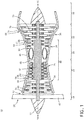
- FIG. 1 is a schematic cross-sectional diagram of a gas turbine engine 10 for an aircraft.
- the engine 10 has a generally longitudinally extending axis or centerline 12 extending forward 14 to aft 16.
- the engine 10 includes, in downstream serial flow relationship, a fan section 18 including a fan 20, a compressor section 22 including a booster or low pressure (LP) compressor 24 and a high pressure (HP) compressor 26, a combustion section 28 including a combustor 30, a turbine section 32 including a HP turbine 34, and a LP turbine 36, and an exhaust section 38.
- LP booster or low pressure
- HP high pressure
- the fan 20 includes a plurality of fan blades 42 disposed radially about the centerline 12.
- the HP compressor 26, the combustor 30, and the HP turbine 34 form a core 44 of the engine 10.
- a core casing 46 surrounds the core 44.
- a LP shaft 50 which is disposed coaxially about the centerline 12 of the engine 10 within the larger diameter annular HP spool 48, drivingly connects the LP turbine 36 to the LP compressor 24 and fan 20.
- the portions of the engine 10 mounted to and rotating with either or both of the shafts 48, 50 are referred to individually or collectively as a rotor 51.
- the LP compressor 24 and the HP compressor 26 respectively include a plurality of compressor stages 52, 54, in which a set of compressor blades 56, 58 rotate relative to a corresponding set of static compressor vanes 60, 62 (also called a nozzle) to compress or pressurize the stream of fluid passing through the stage.
- a single compressor stage 52, 54 multiple compressor blades 56, 58 can be provided in a ring and can extend radially outwardly relative to the centerline 12, from a blade platform to a blade tip, while the corresponding static compressor vanes 60, 62 are positioned downstream of and adjacent to the rotating blades 56, 58. It is noted that the number of blades, vanes, and compressor stages shown in FIG.
- the HP turbine 34 and the LP turbine 36 respectively include a plurality of turbine stages 64, 66, in which a set of turbine blades 68, 70 are rotated relative to a corresponding set of static turbine vanes 72, 74 (also called a nozzle) to extract energy from the stream of fluid passing through the stage.
- a single turbine stage 64, 66 multiple turbine blades 68, 70 can be provided in a ring and can extend radially outwardly relative to the centerline 12, from a blade platform to a blade tip, while the corresponding static turbine vanes 72, 74 are positioned upstream of and adjacent to the rotating blades 68, 70. It is noted that the number of blades, vanes, and turbine stages shown in FIG. 1 were selected for illustrative purposes only, and that other numbers are possible.
- the ambient air supplied by the fan 20 can bypass the engine core 44 and be used for cooling of portions of the engine 10, and/or used to cool or power other aspects of the aircraft.
- the hot portions of the engine are normally downstream of the combustor 30, especially the turbine section 32, with the HP turbine 34 being the hottest portion as it is directly downstream of the combustion section 28.
- Other sources of cooling fluid can be, but is not limited to, fluid discharged from the LP compressor 24 or the HP compressor 26.
- FIG. 2 schematically represents the gas turbine engine 10 shown as a high bypass gas turbine engine, best illustrating cowling structures surrounding the engine core 44.
- the engine 10 includes a fan cowling 40 and a core cowling 76.
- the fan section 18 further includes a nose 78 to which the blades 42 mount.
- a large portion of the air that is drawn into the fan assembly 18 is bypassed to the rear of the engine 10 to generate additional engine thrust.
- the bypassed air passes through an annular-shaped bypass channel 80 between the fan cowling 40 and the core cowling 76 and exits the bypass channel 80 through a fan outlet 82.
- the bypass channel 80 can comprise an angular dimension.
- the core cowling 76 defines the radially inward boundary of the bypass channel 80, and provides a transition surface to a core outlet 84 that extends aft from the core engine 44 such that fluid exhausted from the core engine 44 can pass along a tail 94 defining the exhaust section 38 downstream of and in axial arrangement with the core 44.
- the core cowling 76 can further comprise a channel 92.
- the channel 92 can be disposed within the core cowling 76, in fluid communication with the internal components of the engine core 44.
- the channel 92 exhausts aft of and adjacent to the end of the concave section 90 between the fan outlet 82 and the core outlet 84 through the channel 92.
- Fluid provided through the compressor section 22, the combustor 30, and the turbine section 32 can pass along an inner mainstream channel 98 and exhaust through the core outlet 84.
- the core cowling 76 can be shaped to affect the airflows exhausting from the engine 10 and can comprise a concave section 90.
- the concave section 90 comprises an annular, concave, cross-sectional geometry relative to the engine centerline 12 and can begin forward or aft of the aft end of the fan cowling 40 and extends aft of the fan cowling 40.
- the airflow passing through the engine 10 is utilized to generate thrust, and is exhausted aft of the engine 10.
- Three distinct airflows comprising a bypass airflow 100, a cooling channel airflow 102, and a core exhaust airflow 104 comprise the exhaust airflow for the engine 10.
- the airflows can be annular, exhausting around the circumference of the engine 10.
- the bypass airflow 100 is exhausted from the bypass channel 80 as provided by the fan section 18 and comprises the radially outer-most airflow.
- the core exhaust airflow 104 exhausts from the combustor 30 and the turbine section 32 to generate thrust for the engine 10, and can have a high temperature.
- the cooling exhaust airflow 102 is exhausted form the channel 92 and is disposed between the bypass airflow 100 and the core exhaust airflow 104.
- the cooling exhaust airflow 102 can initially separate the bypass airflow 100 from the core exhaust airflow 104, as the exhausted fluid will eventually mix out downstream of the engine 10.
- the airflows exhausting from the engine can be of varying temperatures and speeds relative to one another.
- the core exhaust airflow 104 has a higher temperature relative to the other airflows, being heated by the combustor 30.
- the outlet geometry of the engine 10 such as the geometry for the fan cowling 40, the core cowling 76, and the tail 94 in combination with the core 44 can comprise a decreasing cross-sectional area to accelerate the airflow as it is exhausted from the engine 10, providing additional thrust.
- airflow within the engine 10 can be held below the speed of sound, while an exhaust nozzle or an exit nozzle structure can accelerate the airflow to near or greater than the speed of sound as the air exhausts, generating additional engine thrust.
- the decreasing cross-sectional area accelerates the flow of air from the bypass channel 80 such that the airflow within the subsonic region 122 is accelerated from a velocity less than the speed of sound to a velocity at or greater than the speed of sound as the airflow enters the fan outlet 82 in the supersonic region 123.
- the cowlings 40, 76 terminate at an annular edge from which the airflows exhaust.
- the end of the fan cowling 40 comprises a convex-shaped nozzle edge 140 or corner.
- Airflow passing through the core outlet 84 at the nozzle edge 140 results in supersonic expansion, such as Prandtl-Meyer expansion, at the nozzle edge 140.
- the supersonic expansion is a centered expansion process that occurs when a supersonic flow turns around a convex corner, such as the nozzle edge 140.
- As can be appreciated in FIG. 3 as the flow of air through the supersonic region 123 turns around the nozzle edge 140 and forms an expansion fan 124 extending from the convex nozzle edge 140.
- the expansion fan 124 creates pressure drops in the form of a supersonic shock wave created at the nozzle edge 140 resultant of the supersonic expansion.
- the fan 124 expands toward the core cowling 76 and is reflected at the flat section 90b into a reflected fan 126. Additionally, the end of the core cowling 76 terminates at a convex corner or edge 142, generating another shock wave 128.
- Both shock waves 124, 128 can move downstream within the airflows exhausting from the engine 10.
- the shock waves 124, 128 and the reflections thereof are supersonic shock waves, reflected between airflow paths or off of engine components such as the core cowling 76.
- the shock waves reduce aerodynamic exhaust performance of the engine 10, reducing overall efficiency. As such, it should be appreciated that minimizing the effect of the shock waves is desirable.
- the airflow exhausted from the bypass channel 80 has a different velocity relative to the air speeds radially inside and outside of it.
- a radially outer edge 132 and a radially inner edge 134 are defined by the difference in adjacent air speeds.
- the shock waves 124, 126, 128, 130 can reflect between the edges 132, 134 having a plurality of reflected shock waves as the airflow moves downstream from the engine 10.
- the shock waves 124, 128 and reflections thereof 126, 130 sequentially increase and decrease airflow pressure, leading to a loss of aerodynamic efficiency.
- the high speed flow causes excessive scrub drag over the exhaust surfaces and further deteriorates aerodynamic performance.
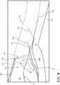
- the inner core cowling 76 comprises the concave section 90, as comparable to the flat section 90b of FIG. 3 , providing deceleration of the fan stream to reduce the strength of the shock waves and reflections thereof as shown in FIG. 3 .
- the airflow from the bypass channel 80 passes through the nozzle 120 accelerating the flow of air from the subsonic region 122 to at or greater than the speed of sound in the supersonic region 123.
- the nozzle 120 can be defined within the concave section 90 or upstream of the concave section 90.
- the concave section 90 can be present for at least a portion of the subsonic region 122 and the supersonic region 123.
- the flow of air within the bypass channel 80 is accelerated to from subsonic to supersonic at a transition between the regions 122, 123.
- the flow of air within the subsonic region 122 is accelerated to the speed of sound and defines the beginning of the supersonic region 123.
- the transition between regions 122, 123 can occur at or before the nozzle 120, and can occur along the concave section 90 of the core cowling 76, or can occur upstream of the beginning of the concave section 90.
- FIG. 4 similar to FIG. 3 , the supersonic airflow passing along the convex nozzle edge 140 and the core cowling edge 142 generates the first shock wave 124 and the second shock wave 128 as well as the reflected shock wave 130.
- the addition of the concave section 90 of the core cowling 76 reduces the strength and effect of the shock waves by allowing for deceleration of the fan airflow. If the flow turns around a concave corner, an oblique shock wave is produced. As the flow passes through the shock, its pressure increases and the flow is decelerated (supersonic compression). However, entropy increases across the oblique shock leading to a loss of compression efficiency.
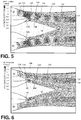
- FIG. 5 a contour chart illustrates the effect of the shock waves 124, 126, 128, 130 created by the supersonic expansion and reflected shock waves from the flat section 90b of the core cowling 76 of FIG. 3 .
- a Mach Number Contour illustrates the relative airspeeds of the airflows exhausting from the engine. The air exhausting from the bypass channel 80 accelerates to at least the speed of sound, generating shock waves at both edges 140, 142. The generated shock waves reflect between the inner and outer edges 132, 134, generating a plurality of supersonic shock waves and reflected shock waves 130 as the air is exhausted from the bypass section 80. The strength of the shock waves can be understood by the speed difference illustrated in the Mach Number Contours between the reflected shock waves.
- FIG. 6 comprising the concave section 90, in comparison to that of FIG. 5 , it should be understood that the strength of the shock waves generated from the bypass section 80 as well as the amount of reflected shock waves 130 downstream decreases.
- the shock waves created have a significantly smaller difference in Mach Number Contour as well as dissipate closer to the tail 94.
- a plot illustrates an efficiency for the typical core cowling at 162 comprising the flat section 90b of the core cowling 76 in comparison to an efficiency for the concave section 90 of the core cowling 76 at 160.
- the overall efficiency based upon a fan nozzle pressure ratio increases over a wide range of pressure ratios with the implementation of the concave section 90.
- the efficiency can be attributed to the overall reduction of the strength of the shock waves by decreasing the fan stream velocity with the concave core cowling.
- the exhaust airstream is streamlined and minimizes the negative effects of the local shock waves generated at the exhaust area of the engine 10. For the subsonic flows (low nozzle pressure ratios) no shock waves are present but the concave cowling decelerates the flow reducing the overall friction drag.
- the concave core cowling structure for the engine provides for airflow deceleration.
- the deceleration of the airflow reduces the strength of aerodynamic shock waves as the supersonic airflow passes over the corners of the fan and core cowlings of the engine.
- the shock waves create aerodynamic losses which can decrease engine performance and therefore, efficiency.
- the reduction of the shock waves increases the airflow streamline being exhausted from the engine and increases overall engine efficiency.
- static pressure adjacent to exhaust surfaces increases with the concave surface, which can increase physical thrust of the engine.
- the concave structure for the core cowling provides for a reduction of wall shear, a reduced-length tail section, and a reduced length for the overall exhaust section for the engine.
- the reduced length of the tail section provides for a reduced overall engine weight and size, which can increase overall engine efficiency.
Landscapes
- Engineering & Computer Science (AREA)
- Mechanical Engineering (AREA)
- General Engineering & Computer Science (AREA)
- Chemical & Material Sciences (AREA)
- Combustion & Propulsion (AREA)
- Structures Of Non-Positive Displacement Pumps (AREA)
- Jet Pumps And Other Pumps (AREA)
Abstract
Description
- Combustion turbine engines are rotary engines that extract energy from a flow of combusted gases passing through the engine onto a multitude of turbine blades. Turbine engines have been used for land and nautical locomotion and power generation, but are most commonly used for aeronautical applications such as propulsion of the aircraft, including helicopters. In terrestrial applications, turbine engines are often used for power generation.
- For efficient operation of aircraft gas turbine engines, that is, to minimize the amount of fuel required to generate a given amount of thrust, it is necessary that the flow output of both the turbine and fan be precisely controlled as to both amount of flow and direction. Controlling the flows is achieved in general by controlling the cross sectional flow areas of the core and fan exhaust nozzles respectively, by either optimally sizing fixed area nozzles for nominal engine operating conditions or employing variable area exhaust nozzles which can be adjusted in area for optimal flow throughout a range of operating conditions. The geometric shape of the exhaust nozzles themselves controls the direction of flow therethrough.
- Both the fan and core exhaust nozzles are functionally defined by components of the engine's nacelle. The nacelle includes a core cowling that provides an aerodynamically efficient cover for the core engine extending threrearound and terminating at the downstream end thereof at the engine's exhaust nozzle. The nacelle also includes an outer fan cowling that surrounds the core cowling, enclosing the blades of the fan and defining with the core cowling, an annular bypass duct which terminates at the fan exhaust nozzle.
- A high bypass gas turbine engine comprising a core comprising a compressor section, combustion section, and turbine section in axial flow arrangement is disclosed. The engine further comprises a fan section upstream of an in axial flow arrangement with the core, an exhaust section downstream of and in axial flow arrangement with the core, and a core cowling surrounding the core and a portion of the exhaust section, and spaced from the exhaust section to define a core outlet between the core cowling and the exhaust section. The engine further comprises a fan cowling surrounding the fan section and a portion of the core cowling being space from the core cowling to define an angular bypass channel having a fan outlet between the fan cowling and the core cowling.
- A cowling assembly for a high bypass gas turbine engine comprising a core cowling and a fan cowling surrounding at least a portion of the core cowling, and spaced from the core cowling to define an angular bypass channel having a fan outlet between the fan cowling and the core cowling is also disclosed. At least a portion of the core cowling immediately downstream of the outlet has a concave cross section.
- A core cowling for a high bypass gas turbine engine comprising a subsonic region and a supersonic region, with an intervening transition, and a concave cross section present at least in the transition is also described.
- In the drawings:
-
FIG. 1 is a schematic, sectional view of a gas turbine engine core. -
FIG. 2 is a schematic view of illustrating core cowlings surrounding the core ofFIG. 1 . -
FIG. 3 is a schematic view of an exhaust section of the engine illustrating a subsonic region and a supersonic region for a typical exhaust system. -
FIG. 4 is a schematic view illustrating a subsonic region and a supersonic region for the concave core cowling ofFIG. 2 . -
FIG. 5 is a gradient view illustrating shock waves from the typical exhaust system ofFIG. 3 . -
FIG. 6 is a gradient view illustrating shock waves from the concave core cowling ofFIG. 4 . -
FIG. 7 is a plot illustrating efficiency over the fan nozzle pressure ratio of the typical exhaust system ofFIG. 5 and the concave core cowling oFIG. 6 . - The described aspects of the present invention are directed to an exhaust system, particularly in a gas turbine engine. For purposes of illustration, the present invention will be described with respect to an aircraft gas turbine engine. It will be understood, however, that the invention is not so limited and can have general applicability in non-aircraft applications, such as other mobile applications and non-mobile industrial, commercial, and residential applications.
- As used herein, the term "forward" or "upstream" refers to moving in a direction toward the engine inlet, or a component being relatively closer to the engine inlet as compared to another component. The term "aft" or "downstream" used in conjunction with "forward" or "upstream" refers to a direction toward the rear or outlet of the engine relative to the engine centerline.
- Additionally, as used herein, the terms "radial" or "radially" refer to a dimension extending between a center longitudinal axis of the engine and an outer engine circumference.
- All directional references (e.g., radial, axial, proximal, distal, upper, lower, upward, downward, left, right, lateral, front, back, top, bottom, above, below, vertical, horizontal, clockwise, counterclockwise, upstream, downstream, aft, etc.) are only used for identification purposes to aid the reader's understanding of the present invention, and do not create limitations, particularly as to the position, orientation, or use of the invention. Connection references (e.g., attached, coupled, connected, and joined) are to be construed broadly and can include intermediate members between a collection of elements and relative movement between elements unless otherwise indicated. As such, connection references do not necessarily infer that two elements are directly connected and in fixed relation to one another. The exemplary drawings are for purposes of illustration only and the dimensions, positions, order and relative sizes reflected in the drawings attached hereto can vary.
-
FIG. 1 is a schematic cross-sectional diagram of agas turbine engine 10 for an aircraft. Theengine 10 has a generally longitudinally extending axis orcenterline 12 extending forward 14 toaft 16. Theengine 10 includes, in downstream serial flow relationship, afan section 18 including afan 20, acompressor section 22 including a booster or low pressure (LP)compressor 24 and a high pressure (HP)compressor 26, acombustion section 28 including acombustor 30, aturbine section 32 including a HPturbine 34, and aLP turbine 36, and anexhaust section 38. - The
fan 20 includes a plurality offan blades 42 disposed radially about thecenterline 12. The HPcompressor 26, thecombustor 30, and the HPturbine 34 form acore 44 of theengine 10. Acore casing 46 surrounds thecore 44. - A HP
shaft 48 disposed coaxially about thecenterline 12 of theengine 10 drivingly connects the HPturbine 34 to the HPcompressor 26. ALP shaft 50, which is disposed coaxially about thecenterline 12 of theengine 10 within the larger diameter annular HPspool 48, drivingly connects theLP turbine 36 to theLP compressor 24 andfan 20. The portions of theengine 10 mounted to and rotating with either or both of theshafts rotor 51. - The
LP compressor 24 and the HPcompressor 26 respectively include a plurality ofcompressor stages compressor blades static compressor vanes 60, 62 (also called a nozzle) to compress or pressurize the stream of fluid passing through the stage. In asingle compressor stage multiple compressor blades centerline 12, from a blade platform to a blade tip, while the corresponding static compressor vanes 60, 62 are positioned downstream of and adjacent to therotating blades FIG. 1 were selected for illustrative purposes only, and that other numbers are possible. Theblades disk 53, which is mounted to the corresponding one of the HP andLP shafts vanes core casing 46 in a circumferential arrangement about therotor 51. - The HP
turbine 34 and theLP turbine 36 respectively include a plurality ofturbine stages turbine blades static turbine vanes 72, 74 (also called a nozzle) to extract energy from the stream of fluid passing through the stage. In asingle turbine stage multiple turbine blades centerline 12, from a blade platform to a blade tip, while the corresponding static turbine vanes 72, 74 are positioned upstream of and adjacent to the rotatingblades FIG. 1 were selected for illustrative purposes only, and that other numbers are possible. - In operation, the rotating
fan 20 supplies ambient air to theLP compressor 24, which then supplies pressurized ambient air to the HPcompressor 26, which further pressurizes the ambient air. The pressurized air from the HPcompressor 26 is mixed with fuel in thecombustor 30 and ignited, thereby generating combustion gases. Some work is extracted from these gases by the HPturbine 34, which drives the HPcompressor 26. The combustion gases are discharged into theLP turbine 36, which extracts additional work to drive theLP compressor 24, and the exhaust gas is ultimately discharged from theengine 10 via theexhaust section 38. The driving of theLP turbine 36 drives theLP shaft 50 to rotate thefan 20 and theLP compressor 24. - Some of the ambient air supplied by the
fan 20 can bypass theengine core 44 and be used for cooling of portions of theengine 10, and/or used to cool or power other aspects of the aircraft. In the context of a turbine engine, the hot portions of the engine are normally downstream of thecombustor 30, especially theturbine section 32, with the HPturbine 34 being the hottest portion as it is directly downstream of thecombustion section 28. Other sources of cooling fluid can be, but is not limited to, fluid discharged from theLP compressor 24 or the HPcompressor 26. -
FIG. 2 schematically represents thegas turbine engine 10 shown as a high bypass gas turbine engine, best illustrating cowling structures surrounding theengine core 44. Theengine 10 includes a fan cowling 40 and acore cowling 76. Thefan section 18 further includes anose 78 to which theblades 42 mount. A large portion of the air that is drawn into thefan assembly 18 is bypassed to the rear of theengine 10 to generate additional engine thrust. The bypassed air passes through an annular-shaped bypass channel 80 between the fan cowling 40 and the core cowling 76 and exits thebypass channel 80 through afan outlet 82. Thebypass channel 80 can comprise an angular dimension. Thecore cowling 76 defines the radially inward boundary of thebypass channel 80, and provides a transition surface to acore outlet 84 that extends aft from thecore engine 44 such that fluid exhausted from thecore engine 44 can pass along atail 94 defining theexhaust section 38 downstream of and in axial arrangement with thecore 44. - The
core cowling 76 can further comprise achannel 92. Thechannel 92 can be disposed within thecore cowling 76, in fluid communication with the internal components of theengine core 44. Thechannel 92 exhausts aft of and adjacent to the end of theconcave section 90 between thefan outlet 82 and thecore outlet 84 through thechannel 92. Fluid provided through thecompressor section 22, thecombustor 30, and theturbine section 32 can pass along an innermainstream channel 98 and exhaust through thecore outlet 84. Thecore cowling 76 can be shaped to affect the airflows exhausting from theengine 10 and can comprise aconcave section 90. Theconcave section 90 comprises an annular, concave, cross-sectional geometry relative to theengine centerline 12 and can begin forward or aft of the aft end of thefan cowling 40 and extends aft of thefan cowling 40. - During operation, the airflow passing through the
engine 10 is utilized to generate thrust, and is exhausted aft of theengine 10. Three distinct airflows comprising abypass airflow 100, a coolingchannel airflow 102, and acore exhaust airflow 104 comprise the exhaust airflow for theengine 10. The airflows can be annular, exhausting around the circumference of theengine 10. Thebypass airflow 100 is exhausted from thebypass channel 80 as provided by thefan section 18 and comprises the radially outer-most airflow. Thecore exhaust airflow 104 exhausts from thecombustor 30 and theturbine section 32 to generate thrust for theengine 10, and can have a high temperature. The coolingexhaust airflow 102 is exhausted form thechannel 92 and is disposed between thebypass airflow 100 and thecore exhaust airflow 104. The coolingexhaust airflow 102 can initially separate thebypass airflow 100 from thecore exhaust airflow 104, as the exhausted fluid will eventually mix out downstream of theengine 10. - It should be appreciated that the airflows exhausting from the engine can be of varying temperatures and speeds relative to one another. Typically, the
core exhaust airflow 104 has a higher temperature relative to the other airflows, being heated by thecombustor 30. Furthermore, the coolingexhaust airflow 102 typically is exhausted at a speed slower than the other exhaust flows, having a velocity significantly lower than the speed of sound (Mach=1 speed), while thebypass airflow 100 and the core exhaust airflow speeds are typically near or exceeding the speed of sound. - Furthermore, the outlet geometry of the
engine 10, such as the geometry for thefan cowling 40, thecore cowling 76, and thetail 94 in combination with the core 44 can comprise a decreasing cross-sectional area to accelerate the airflow as it is exhausted from theengine 10, providing additional thrust. As such, airflow within theengine 10 can be held below the speed of sound, while an exhaust nozzle or an exit nozzle structure can accelerate the airflow to near or greater than the speed of sound as the air exhausts, generating additional engine thrust. - Turning to
FIG. 3 , the engine exhaust structure is shown illustrating the airflow after exhausting from thebypass channel 80. It should be appreciated that the engine shown inFIG. 3 comprises aflat section 90b as compared to theconcave section 90 ofFIG. 2 . The airflow from thebypass channel 80 feeds thefan outlet 82. Thefan outlet 82 can further be defined by a decreasing cross-sectional area such that a minimum cross-sectional area defines anozzle 120. Thefan outlet 82 can further define asubsonic region 122 upstream of thenozzle 120 and asupersonic region 123 downstream of thenozzle 120. The decreasing cross-sectional area accelerates the flow of air from thebypass channel 80 such that the airflow within thesubsonic region 122 is accelerated from a velocity less than the speed of sound to a velocity at or greater than the speed of sound as the airflow enters thefan outlet 82 in thesupersonic region 123. - The
cowlings fan cowling 40 comprises a convex-shapednozzle edge 140 or corner. Airflow passing through thecore outlet 84 at thenozzle edge 140 results in supersonic expansion, such as Prandtl-Meyer expansion, at thenozzle edge 140. The supersonic expansion is a centered expansion process that occurs when a supersonic flow turns around a convex corner, such as thenozzle edge 140. As can be appreciated inFIG. 3 , as the flow of air through thesupersonic region 123 turns around thenozzle edge 140 and forms anexpansion fan 124 extending from theconvex nozzle edge 140. Theexpansion fan 124 creates pressure drops in the form of a supersonic shock wave created at thenozzle edge 140 resultant of the supersonic expansion. Thefan 124 expands toward thecore cowling 76 and is reflected at theflat section 90b into a reflectedfan 126. Additionally, the end of thecore cowling 76 terminates at a convex corner oredge 142, generating anothershock wave 128. Bothshock waves engine 10. Theshock waves core cowling 76. The shock waves reduce aerodynamic exhaust performance of theengine 10, reducing overall efficiency. As such, it should be appreciated that minimizing the effect of the shock waves is desirable. - The airflow exhausted from the
bypass channel 80 has a different velocity relative to the air speeds radially inside and outside of it. As such, a radiallyouter edge 132 and a radiallyinner edge 134 are defined by the difference in adjacent air speeds. Thus, theshock waves edges engine 10. As the exhaust flows turn around theedges shock waves - Turning to
FIG. 4 , theinner core cowling 76 comprises theconcave section 90, as comparable to theflat section 90b ofFIG. 3 , providing deceleration of the fan stream to reduce the strength of the shock waves and reflections thereof as shown inFIG. 3 . The airflow from thebypass channel 80 passes through thenozzle 120 accelerating the flow of air from thesubsonic region 122 to at or greater than the speed of sound in thesupersonic region 123. It should be appreciated that thenozzle 120 can be defined within theconcave section 90 or upstream of theconcave section 90. As such, theconcave section 90 can be present for at least a portion of thesubsonic region 122 and thesupersonic region 123. - It should be further appreciated that the flow of air within the
bypass channel 80 is accelerated to from subsonic to supersonic at a transition between theregions subsonic region 122 is accelerated to the speed of sound and defines the beginning of thesupersonic region 123. The transition betweenregions nozzle 120, and can occur along theconcave section 90 of thecore cowling 76, or can occur upstream of the beginning of theconcave section 90. - In
FIG. 4 , similar toFIG. 3 , the supersonic airflow passing along theconvex nozzle edge 140 and thecore cowling edge 142 generates thefirst shock wave 124 and thesecond shock wave 128 as well as the reflectedshock wave 130. The addition of theconcave section 90 of thecore cowling 76, as comparable to theflat section 90b ofFIG. 3 , reduces the strength and effect of the shock waves by allowing for deceleration of the fan airflow. If the flow turns around a concave corner, an oblique shock wave is produced. As the flow passes through the shock, its pressure increases and the flow is decelerated (supersonic compression). However, entropy increases across the oblique shock leading to a loss of compression efficiency. However, when the compression is done over a smooth concave surface, instead of a concave corner, the compression is done through an infinite number of infinitesimally weak Mach waves. The entire process is isentropic and thus the most efficient. The overall performance loss from the created and reflected shock waves is minimized. The effect of compression increases with the increase of wall curvature, up to coalescence of Mach waves. It is contemplated that the transition from a subsonic speed to a supersonic speed occurs forward of the radial expanse of theconcave section 90. - Turning now to
FIG. 5 , a contour chart illustrates the effect of theshock waves flat section 90b of thecore cowling 76 ofFIG. 3 . A Mach Number Contour illustrates the relative airspeeds of the airflows exhausting from the engine. The air exhausting from thebypass channel 80 accelerates to at least the speed of sound, generating shock waves at bothedges outer edges shock waves 130 as the air is exhausted from thebypass section 80. The strength of the shock waves can be understood by the speed difference illustrated in the Mach Number Contours between the reflected shock waves. Turning now toFIG. 6 comprising theconcave section 90, in comparison to that ofFIG. 5 , it should be understood that the strength of the shock waves generated from thebypass section 80 as well as the amount of reflectedshock waves 130 downstream decreases. The shock waves created have a significantly smaller difference in Mach Number Contour as well as dissipate closer to thetail 94. - Looking at
FIG. 7 , a plot illustrates an efficiency for the typical core cowling at 162 comprising theflat section 90b of thecore cowling 76 in comparison to an efficiency for theconcave section 90 of thecore cowling 76 at 160. As can be appreciated, the overall efficiency based upon a fan nozzle pressure ratio increases over a wide range of pressure ratios with the implementation of theconcave section 90. The efficiency can be attributed to the overall reduction of the strength of the shock waves by decreasing the fan stream velocity with the concave core cowling. The exhaust airstream is streamlined and minimizes the negative effects of the local shock waves generated at the exhaust area of theengine 10. For the subsonic flows (low nozzle pressure ratios) no shock waves are present but the concave cowling decelerates the flow reducing the overall friction drag. - It should be appreciated that the concave core cowling structure for the engine provides for airflow deceleration. The deceleration of the airflow reduces the strength of aerodynamic shock waves as the supersonic airflow passes over the corners of the fan and core cowlings of the engine. The shock waves create aerodynamic losses which can decrease engine performance and therefore, efficiency. The reduction of the shock waves increases the airflow streamline being exhausted from the engine and increases overall engine efficiency. Furthermore, static pressure adjacent to exhaust surfaces increases with the concave surface, which can increase physical thrust of the engine.
- Furthermore, the concave structure for the core cowling provides for a reduction of wall shear, a reduced-length tail section, and a reduced length for the overall exhaust section for the engine. The reduced length of the tail section provides for a reduced overall engine weight and size, which can increase overall engine efficiency.
- This written description uses examples to disclose the invention, including the preferred mode, and to enable any person skilled in the art to practice the invention, including making and using any devices or systems and performing any incorporated methods. The patentable scope of the invention is defined by the claims, and can include other examples that occur to those skilled in the art. Such other examples are intended to be within the scope of the claims if they have structural elements that do not differ from the literal language of the claims, or if they include equivalent structural elements with insubstantial differences from the literal languages of the claims.
- Various aspects and embodiments of the present invention are defined by the following numbered clauses:
- 1. A high bypass gas turbine engine comprising:
- a core comprising a compressor section, combustion section, and turbine section in axial flow arrangement;
- a fan section upstream of and in axial flow arrangement with the core;
- an exhaust section downstream of and in axial flow arrangement with the core;
- a core cowling surrounding the core and a portion of the exhaust section, and spaced from the exhaust section to define a core outlet between the core cowling and the exhaust section; and
- a fan cowling surrounding the fan section and a portion of the core cowling, and spaced from the core cowling to define an angular bypass channel having a fan outlet between the fan cowling and the core cowling;
- 2. The high bypass gas turbine engine of clause 1, wherein the concave cross section extends upstream of the fan outlet.
- 3. The high bypass gas turbine engine of any preceding clause, wherein the bypass channel has a subsonic flow region and the concave cross section is present for at least a portion of the subsonic flow region.
- 4. The high bypass gas turbine engine of any preceding clause, wherein the bypass channel has a supersonic flow region and the concave cross section is present for at least a portion of the supersonic flow region.
- 5. The high bypass gas turbine engine of any preceding clause, wherein the bypass channel has a subsonic to supersonic transition between the subsonic and supersonic flow regions and the concave cross section is present at least at the transition.
- 6. The high bypass gas turbine engine of any preceding clause, wherein the concave cross section spans the transition.
- 7. The high bypass gas turbine engine of any preceding clause, wherein the concave cross section extends downstream of the fan outlet.
- 8. The high bypass gas turbine engine of any preceding clause, wherein the concave cross section terminates at the core outlet.
- 9. A cowling assembly for a high bypass gas turbine engine comprising:
- a core cowling; and
- a fan cowling surrounding at least a portion of the core cowling, and spaced from the core cowling to define an angular bypass channel having a fan outlet between the fan cowling and the core cowling;
- 10. The cowling assembly of any preceding clause, wherein the concave cross section extends upstream of the fan outlet.
- 11. The cowling assembly of any preceding clause, wherein the bypass channel has a subsonic flow region and the concave cross section is present for at least a portion of the subsonic flow region.
- 12. The cowling assembly of any preceding clause, wherein the bypass channel has a supersonic flow region and the concave cross section is present for at least a portion of the supersonic flow region.
- 13. The cowling assembly of any preceding clause, wherein the bypass channel has a subsonic to supersonic transition between the subsonic and supersonic flow regions and the concave cross section is present at least at the transition.
- 14. The cowling assembly of any preceding clause, wherein the concave cross section spans the transition.
- 15. The cowling assembly of any preceding clause, wherein the concave cross section extends downstream of the fan outlet.
- 16. The cowling assembly of any preceding clause, wherein the concave cross section terminates at a downstream end of the core cowling.
- 17. The cowling assembly of any preceding clause, wherein the concave cross section extends about the circumference of the core cowling.
- 18. A core cowling for a high bypass gas turbine engine comprising a subsonic region and a supersonic region, with an intervening transition, and a concave cross section present at least at the transition.
- 19. The core cowling according to any preceding clause, wherein the concave cross section is downstream of the transition.
- 20. The core cowling according to any preceding clause, wherein the concave cross section is upstream of the transition.
- 21. The core cowling according to any preceding clause, wherein the concave cross section spans the transition.
- 22. The core cowling according to any preceding clause, wherein the concave cross section terminates at a downstream end of the core cowling.
Claims (10)
- A cowling assembly for a high bypass gas turbine engine comprising:a core cowling (76); anda fan cowling (40) surrounding at least a portion of the core cowling (76), and spaced from the core cowling (76) to define an angular bypass channel (80) having a fan outlet (82) between the fan cowling (40) and the core cowling (76);wherein at least a portion of the core cowling (76) immediately downstream of the fan outlet (82) has a concave cross section (90).
- The cowling assembly of claim 1, wherein the concave cross section (90) extends upstream of the fan outlet (82).
- The cowling assembly of any preceding claim, wherein the bypass channel (80) has a subsonic flow (122) region and the concave cross section (90) is present for at least a portion of the subsonic flow region (122).
- The cowling assembly of claim 3, wherein the bypass channel (80) has a supersonic flow region (123) and the concave cross section (90) is present for at least a portion of the supersonic flow region (123).
- The cowling assembly of claim 4, wherein the bypass channel (80) has a subsonic to supersonic transition between the subsonic and supersonic flow regions and the concave cross section (90) is present at least at the transition.
- The cowling assembly of any preceding claim, wherein the concave cross section (90) spans the transition.
- The cowling assembly of any preceding claim, wherein the concave cross section (90) extends downstream of the fan outlet (82).
- The cowling assembly of any preceding claim, wherein the concave cross section (90) terminates at a downstream end of the core cowling (76).
- The cowling assembly of any preceding claim, wherein the concave cross section (90) terminates at a channel (92) disposed in the core cowling (76).
- The cowling assembly of any preceding claim, wherein the concave cross section (90) extends about the circumference of the core cowling (76).
Applications Claiming Priority (1)
| Application Number | Priority Date | Filing Date | Title |
|---|---|---|---|
| PL414889A PL414889A1 (en) | 2015-11-23 | 2015-11-23 | Jet engine outlet compression cowling |
Publications (2)
| Publication Number | Publication Date |
|---|---|
| EP3171009A1 true EP3171009A1 (en) | 2017-05-24 |
| EP3171009B1 EP3171009B1 (en) | 2021-07-28 |
Family
ID=57345818
Family Applications (1)
| Application Number | Title | Priority Date | Filing Date |
|---|---|---|---|
| EP16199376.1A Active EP3171009B1 (en) | 2015-11-23 | 2016-11-17 | Compression cowl for jet engine exhaust |
Country Status (7)
| Country | Link |
|---|---|
| US (1) | US10920713B2 (en) |
| EP (1) | EP3171009B1 (en) |
| JP (1) | JP6378736B2 (en) |
| CN (1) | CN107013268B (en) |
| BR (1) | BR102016027313A2 (en) |
| CA (1) | CA2948263C (en) |
| PL (1) | PL414889A1 (en) |
Cited By (4)
| Publication number | Priority date | Publication date | Assignee | Title |
|---|---|---|---|---|
| EP3670885A1 (en) * | 2018-12-21 | 2020-06-24 | Rolls-Royce plc | Turbine engine core and bypass flows |
| US10760530B2 (en) | 2018-12-21 | 2020-09-01 | Rolls-Royce Plc | Fan arrangement for a gas turbine engine |
| US11053947B2 (en) | 2018-12-21 | 2021-07-06 | Rolls-Royce Plc | Turbine engine |
| US11204037B2 (en) | 2018-12-21 | 2021-12-21 | Rolls-Royce Plc | Turbine engine |
Families Citing this family (7)
| Publication number | Priority date | Publication date | Assignee | Title |
|---|---|---|---|---|
| PL420340A1 (en) * | 2017-01-30 | 2018-08-13 | General Electric Company | Reducing of the outlet nozzle shock wave |
| US11454128B2 (en) * | 2018-08-06 | 2022-09-27 | General Electric Company | Fairing assembly |
| US11300002B2 (en) | 2018-12-07 | 2022-04-12 | Pratt & Whitney Canada Corp. | Static take-off port |
| FR3095244B1 (en) * | 2019-04-17 | 2022-06-24 | Safran Aircraft Engines | Method for using a turbojet nacelle air inlet during a thrust phase and during a thrust reversal phase |
| WO2021138538A1 (en) * | 2020-01-03 | 2021-07-08 | University Of Kansas | Methods and systems of mitigating high-speed jet noise |
| US11746726B2 (en) * | 2020-05-05 | 2023-09-05 | Rohr, Inc. | Aircraft propulsion system nozzle with internal flow passage |
| CN114320660B (en) * | 2022-01-05 | 2023-02-03 | 北京理工大学 | A wide-speed ramjet engine based on axial supersonic rheological geometry fan |
Citations (6)
| Publication number | Priority date | Publication date | Assignee | Title |
|---|---|---|---|---|
| EP0953506A2 (en) * | 1996-03-04 | 1999-11-03 | The Boeing Company | Flow control apparatus for gas turbine engine installation pressure relief doors |
| US6178740B1 (en) * | 1999-02-25 | 2001-01-30 | The Boeing Company | Turbo fan engine nacelle exhaust system with concave primary nozzle plug |
| US20020178711A1 (en) * | 2001-05-31 | 2002-12-05 | Steven Martens | Truncated chevron exhaust nozzle |
| US20050081509A1 (en) * | 2003-10-20 | 2005-04-21 | Johnson James E. | Flade gas turbine engine with fixed geometry inlet |
| US20140259631A1 (en) * | 2013-03-15 | 2014-09-18 | Northrop Grumman Systems Corporation | Internal/external single expansion ramp nozzle with integrated third stream |
| US20150075169A1 (en) * | 2013-09-19 | 2015-03-19 | Pratt & Whitney Canada Corp. | Integrated turbine exhaust struts and mixer of turbofan engine |
Family Cites Families (18)
| Publication number | Priority date | Publication date | Assignee | Title |
|---|---|---|---|---|
| GB1418665A (en) | 1972-04-27 | 1975-12-24 | Rolls Royce | Fluid flow ducts |
| US3881315A (en) * | 1973-03-19 | 1975-05-06 | Gen Electric | Fan duct flow deflector |
| US3873235A (en) * | 1973-10-01 | 1975-03-25 | Gen Electric | Variable pitch turbofan engine |
| US4567960A (en) * | 1982-08-23 | 1986-02-04 | The Boeing Company | Fixed geometry controlled entrainment ventilated convergent nozzle and method |
| US6658839B2 (en) | 2002-02-28 | 2003-12-09 | The Boeing Company | Convergent/divergent segmented exhaust nozzle |
| US6969028B2 (en) | 2003-01-22 | 2005-11-29 | The Boeing Company | Scarf nozzle for a jet engine and method of using the same |
| US7055329B2 (en) * | 2003-03-31 | 2006-06-06 | General Electric Company | Method and apparatus for noise attenuation for gas turbine engines using at least one synthetic jet actuator for injecting air |
| FR2855558B1 (en) * | 2003-05-28 | 2005-07-15 | Snecma Moteurs | TURBOMACHINE TUBE WITH NOISE REDUCTION |
| US7900433B2 (en) | 2006-08-31 | 2011-03-08 | United Technologies Corporation | Fan exhaust nozzle for turbofan engine |
| FR2921977B1 (en) * | 2007-10-08 | 2012-09-21 | Airbus France | DOUBLE FLOW TURBOMOTEUR FOR AIRCRAFT |
| US8393158B2 (en) | 2007-10-24 | 2013-03-12 | Gulfstream Aerospace Corporation | Low shock strength inlet |
| FR2923270B1 (en) * | 2007-11-06 | 2014-01-31 | Airbus France | TURBOMOTEUR WITH ADAPTED COLD FLUX TUBE |
| FR2929334B1 (en) | 2008-03-31 | 2012-06-01 | Airbus France | DEVICE FOR REDUCING NOISE GENERATION BY AIRCRAFT REACTOR WITH BLEED FLUID CONDUITS |
| US9181899B2 (en) | 2008-08-27 | 2015-11-10 | General Electric Company | Variable slope exhaust nozzle |
| US8511987B2 (en) | 2009-11-20 | 2013-08-20 | United Technologies Corporation | Engine bearing support |
| FR2983917B1 (en) * | 2011-12-07 | 2013-12-27 | Snecma | CONVERGENT-DIVERGENT TUYERE OF TURBOMACHINE |
| EP3546726B1 (en) * | 2013-03-14 | 2021-12-15 | Raytheon Technologies Corporation | Turbofan engine assembly methods |
| CN104712457A (en) | 2013-12-11 | 2015-06-17 | 黄乐歌 | Hypersonic aircraft engine with low fuel consumption |
-
2015
- 2015-11-23 PL PL414889A patent/PL414889A1/en unknown
-
2016
- 2016-11-14 JP JP2016221093A patent/JP6378736B2/en active Active
- 2016-11-14 CA CA2948263A patent/CA2948263C/en active Active
- 2016-11-17 EP EP16199376.1A patent/EP3171009B1/en active Active
- 2016-11-22 BR BR102016027313-7A patent/BR102016027313A2/en not_active Application Discontinuation
- 2016-11-23 US US15/360,080 patent/US10920713B2/en active Active
- 2016-11-23 CN CN201611037277.7A patent/CN107013268B/en active Active
Patent Citations (6)
| Publication number | Priority date | Publication date | Assignee | Title |
|---|---|---|---|---|
| EP0953506A2 (en) * | 1996-03-04 | 1999-11-03 | The Boeing Company | Flow control apparatus for gas turbine engine installation pressure relief doors |
| US6178740B1 (en) * | 1999-02-25 | 2001-01-30 | The Boeing Company | Turbo fan engine nacelle exhaust system with concave primary nozzle plug |
| US20020178711A1 (en) * | 2001-05-31 | 2002-12-05 | Steven Martens | Truncated chevron exhaust nozzle |
| US20050081509A1 (en) * | 2003-10-20 | 2005-04-21 | Johnson James E. | Flade gas turbine engine with fixed geometry inlet |
| US20140259631A1 (en) * | 2013-03-15 | 2014-09-18 | Northrop Grumman Systems Corporation | Internal/external single expansion ramp nozzle with integrated third stream |
| US20150075169A1 (en) * | 2013-09-19 | 2015-03-19 | Pratt & Whitney Canada Corp. | Integrated turbine exhaust struts and mixer of turbofan engine |
Cited By (7)
| Publication number | Priority date | Publication date | Assignee | Title |
|---|---|---|---|---|
| EP3670885A1 (en) * | 2018-12-21 | 2020-06-24 | Rolls-Royce plc | Turbine engine core and bypass flows |
| US10760530B2 (en) | 2018-12-21 | 2020-09-01 | Rolls-Royce Plc | Fan arrangement for a gas turbine engine |
| US11053947B2 (en) | 2018-12-21 | 2021-07-06 | Rolls-Royce Plc | Turbine engine |
| US11204037B2 (en) | 2018-12-21 | 2021-12-21 | Rolls-Royce Plc | Turbine engine |
| US11339713B2 (en) | 2018-12-21 | 2022-05-24 | Rolls-Royce Plc | Large-scale bypass fan configuration for turbine engine core and bypass flows |
| US11988169B2 (en) | 2018-12-21 | 2024-05-21 | Rolls-Royce Plc | Fan arrangement for a gas turbine engine |
| US12163464B2 (en) | 2018-12-21 | 2024-12-10 | Rolls-Royce Plc | Turbine engine core and bypass flows having a defined fan-turbine radial distance |
Also Published As
| Publication number | Publication date |
|---|---|
| EP3171009B1 (en) | 2021-07-28 |
| US10920713B2 (en) | 2021-02-16 |
| JP6378736B2 (en) | 2018-08-22 |
| JP2017096279A (en) | 2017-06-01 |
| PL414889A1 (en) | 2017-06-05 |
| CN107013268A (en) | 2017-08-04 |
| BR102016027313A2 (en) | 2017-07-25 |
| CA2948263C (en) | 2021-09-28 |
| CN107013268B (en) | 2020-03-06 |
| CA2948263A1 (en) | 2017-05-23 |
| US20170145957A1 (en) | 2017-05-25 |
Similar Documents
| Publication | Publication Date | Title |
|---|---|---|
| US10920713B2 (en) | Compression cowl for jet engine exhaust | |
| EP2685065B1 (en) | Propeller gas turbine engine | |
| EP3284942B1 (en) | Direct drive aft fan engine | |
| EP3734053B1 (en) | Adaptive vertical lift engine (avle) fan | |
| US11884414B2 (en) | Supersonic aircraft turbofan engine | |
| WO2014018126A2 (en) | High pressure muffling devices | |
| CN104520542A (en) | Turbomachine comprising a plurality of fixed radial blades mounted upstream of the fan | |
| CN101327844A (en) | Thrust generators for propulsion systems | |
| CN115788679B (en) | Waste heat recovery system | |
| US20180216576A1 (en) | Supersonic turbofan engine | |
| EP3076079B1 (en) | Combustion equipment | |
| US10585007B2 (en) | Air temperature sensor | |
| EP2077963B1 (en) | Gas turbine nacelle comprising a passive boundary layer bleed system | |
| US11807379B2 (en) | Turbofan engine, nacelle thereof, and associated method of operation | |
| US11078870B2 (en) | Method and system for a stowable bell-mouth scoop | |
| US11268390B2 (en) | Vortex generators for turbine engine exhaust | |
| WO2008058368A1 (en) | Nacelle drag reduction device for a turbofan gas turbine engine | |
| CN110015432B (en) | Engine nacelle for aircraft | |
| CN118532280A (en) | Engine with open fan to reduce boundary layer induced distortion | |
| US20250368345A1 (en) | Unducted Thrust Producing System | |
| US11920539B1 (en) | Gas turbine exhaust nozzle noise abatement | |
| US12618381B2 (en) | Gas turbine exhaust nozzle noise abatement | |
| US20260098547A1 (en) | Lift fan assembly for an aircraft | |
| CN118728492A (en) | Ductless airfoil assembly | |
| CN119222002A (en) | Ductless airfoil assembly |
Legal Events
| Date | Code | Title | Description |
|---|---|---|---|
| PUAI | Public reference made under article 153(3) epc to a published international application that has entered the european phase |
Free format text: ORIGINAL CODE: 0009012 |
|
| STAA | Information on the status of an ep patent application or granted ep patent |
Free format text: STATUS: THE APPLICATION HAS BEEN PUBLISHED |
|
| AK | Designated contracting states |
Kind code of ref document: A1 Designated state(s): AL AT BE BG CH CY CZ DE DK EE ES FI FR GB GR HR HU IE IS IT LI LT LU LV MC MK MT NL NO PL PT RO RS SE SI SK SM TR |
|
| AX | Request for extension of the european patent |
Extension state: BA ME |
|
| STAA | Information on the status of an ep patent application or granted ep patent |
Free format text: STATUS: REQUEST FOR EXAMINATION WAS MADE |
|
| 17P | Request for examination filed |
Effective date: 20171124 |
|
| RBV | Designated contracting states (corrected) |
Designated state(s): AL AT BE BG CH CY CZ DE DK EE ES FI FR GB GR HR HU IE IS IT LI LT LU LV MC MK MT NL NO PL PT RO RS SE SI SK SM TR |
|
| STAA | Information on the status of an ep patent application or granted ep patent |
Free format text: STATUS: EXAMINATION IS IN PROGRESS |
|
| 17Q | First examination report despatched |
Effective date: 20200616 |
|
| GRAP | Despatch of communication of intention to grant a patent |
Free format text: ORIGINAL CODE: EPIDOSNIGR1 |
|
| STAA | Information on the status of an ep patent application or granted ep patent |
Free format text: STATUS: GRANT OF PATENT IS INTENDED |
|
| INTG | Intention to grant announced |
Effective date: 20210219 |
|
| GRAS | Grant fee paid |
Free format text: ORIGINAL CODE: EPIDOSNIGR3 |
|
| GRAA | (expected) grant |
Free format text: ORIGINAL CODE: 0009210 |
|
| STAA | Information on the status of an ep patent application or granted ep patent |
Free format text: STATUS: THE PATENT HAS BEEN GRANTED |
|
| AK | Designated contracting states |
Kind code of ref document: B1 Designated state(s): AL AT BE BG CH CY CZ DE DK EE ES FI FR GB GR HR HU IE IS IT LI LT LU LV MC MK MT NL NO PL PT RO RS SE SI SK SM TR |
|
| REG | Reference to a national code |
Ref country code: GB Ref legal event code: FG4D |
|
| REG | Reference to a national code |
Ref country code: CH Ref legal event code: EP |
|
| REG | Reference to a national code |
Ref country code: DE Ref legal event code: R096 Ref document number: 602016061200 Country of ref document: DE |
|
| REG | Reference to a national code |
Ref country code: AT Ref legal event code: REF Ref document number: 1414939 Country of ref document: AT Kind code of ref document: T Effective date: 20210815 |
|
| REG | Reference to a national code |
Ref country code: IE Ref legal event code: FG4D |
|
| REG | Reference to a national code |
Ref country code: LT Ref legal event code: MG9D |
|
| REG | Reference to a national code |
Ref country code: NL Ref legal event code: MP Effective date: 20210728 |
|
| REG | Reference to a national code |
Ref country code: AT Ref legal event code: MK05 Ref document number: 1414939 Country of ref document: AT Kind code of ref document: T Effective date: 20210728 |
|
| PG25 | Lapsed in a contracting state [announced via postgrant information from national office to epo] |
Ref country code: SE Free format text: LAPSE BECAUSE OF FAILURE TO SUBMIT A TRANSLATION OF THE DESCRIPTION OR TO PAY THE FEE WITHIN THE PRESCRIBED TIME-LIMIT Effective date: 20210728 Ref country code: RS Free format text: LAPSE BECAUSE OF FAILURE TO SUBMIT A TRANSLATION OF THE DESCRIPTION OR TO PAY THE FEE WITHIN THE PRESCRIBED TIME-LIMIT Effective date: 20210728 Ref country code: HR Free format text: LAPSE BECAUSE OF FAILURE TO SUBMIT A TRANSLATION OF THE DESCRIPTION OR TO PAY THE FEE WITHIN THE PRESCRIBED TIME-LIMIT Effective date: 20210728 Ref country code: LT Free format text: LAPSE BECAUSE OF FAILURE TO SUBMIT A TRANSLATION OF THE DESCRIPTION OR TO PAY THE FEE WITHIN THE PRESCRIBED TIME-LIMIT Effective date: 20210728 Ref country code: BG Free format text: LAPSE BECAUSE OF FAILURE TO SUBMIT A TRANSLATION OF THE DESCRIPTION OR TO PAY THE FEE WITHIN THE PRESCRIBED TIME-LIMIT Effective date: 20211028 Ref country code: AT Free format text: LAPSE BECAUSE OF FAILURE TO SUBMIT A TRANSLATION OF THE DESCRIPTION OR TO PAY THE FEE WITHIN THE PRESCRIBED TIME-LIMIT Effective date: 20210728 Ref country code: NO Free format text: LAPSE BECAUSE OF FAILURE TO SUBMIT A TRANSLATION OF THE DESCRIPTION OR TO PAY THE FEE WITHIN THE PRESCRIBED TIME-LIMIT Effective date: 20211028 Ref country code: NL Free format text: LAPSE BECAUSE OF FAILURE TO SUBMIT A TRANSLATION OF THE DESCRIPTION OR TO PAY THE FEE WITHIN THE PRESCRIBED TIME-LIMIT Effective date: 20210728 Ref country code: PT Free format text: LAPSE BECAUSE OF FAILURE TO SUBMIT A TRANSLATION OF THE DESCRIPTION OR TO PAY THE FEE WITHIN THE PRESCRIBED TIME-LIMIT Effective date: 20211129 Ref country code: FI Free format text: LAPSE BECAUSE OF FAILURE TO SUBMIT A TRANSLATION OF THE DESCRIPTION OR TO PAY THE FEE WITHIN THE PRESCRIBED TIME-LIMIT Effective date: 20210728 Ref country code: ES Free format text: LAPSE BECAUSE OF FAILURE TO SUBMIT A TRANSLATION OF THE DESCRIPTION OR TO PAY THE FEE WITHIN THE PRESCRIBED TIME-LIMIT Effective date: 20210728 |
|
| PG25 | Lapsed in a contracting state [announced via postgrant information from national office to epo] |
Ref country code: PL Free format text: LAPSE BECAUSE OF FAILURE TO SUBMIT A TRANSLATION OF THE DESCRIPTION OR TO PAY THE FEE WITHIN THE PRESCRIBED TIME-LIMIT Effective date: 20210728 Ref country code: LV Free format text: LAPSE BECAUSE OF FAILURE TO SUBMIT A TRANSLATION OF THE DESCRIPTION OR TO PAY THE FEE WITHIN THE PRESCRIBED TIME-LIMIT Effective date: 20210728 Ref country code: GR Free format text: LAPSE BECAUSE OF FAILURE TO SUBMIT A TRANSLATION OF THE DESCRIPTION OR TO PAY THE FEE WITHIN THE PRESCRIBED TIME-LIMIT Effective date: 20211029 |
|
| PG25 | Lapsed in a contracting state [announced via postgrant information from national office to epo] |
Ref country code: DK Free format text: LAPSE BECAUSE OF FAILURE TO SUBMIT A TRANSLATION OF THE DESCRIPTION OR TO PAY THE FEE WITHIN THE PRESCRIBED TIME-LIMIT Effective date: 20210728 |
|
| REG | Reference to a national code |
Ref country code: DE Ref legal event code: R097 Ref document number: 602016061200 Country of ref document: DE |
|
| PG25 | Lapsed in a contracting state [announced via postgrant information from national office to epo] |
Ref country code: SM Free format text: LAPSE BECAUSE OF FAILURE TO SUBMIT A TRANSLATION OF THE DESCRIPTION OR TO PAY THE FEE WITHIN THE PRESCRIBED TIME-LIMIT Effective date: 20210728 Ref country code: SK Free format text: LAPSE BECAUSE OF FAILURE TO SUBMIT A TRANSLATION OF THE DESCRIPTION OR TO PAY THE FEE WITHIN THE PRESCRIBED TIME-LIMIT Effective date: 20210728 Ref country code: RO Free format text: LAPSE BECAUSE OF FAILURE TO SUBMIT A TRANSLATION OF THE DESCRIPTION OR TO PAY THE FEE WITHIN THE PRESCRIBED TIME-LIMIT Effective date: 20210728 Ref country code: EE Free format text: LAPSE BECAUSE OF FAILURE TO SUBMIT A TRANSLATION OF THE DESCRIPTION OR TO PAY THE FEE WITHIN THE PRESCRIBED TIME-LIMIT Effective date: 20210728 Ref country code: CZ Free format text: LAPSE BECAUSE OF FAILURE TO SUBMIT A TRANSLATION OF THE DESCRIPTION OR TO PAY THE FEE WITHIN THE PRESCRIBED TIME-LIMIT Effective date: 20210728 Ref country code: AL Free format text: LAPSE BECAUSE OF FAILURE TO SUBMIT A TRANSLATION OF THE DESCRIPTION OR TO PAY THE FEE WITHIN THE PRESCRIBED TIME-LIMIT Effective date: 20210728 |
|
| PLBE | No opposition filed within time limit |
Free format text: ORIGINAL CODE: 0009261 |
|
| STAA | Information on the status of an ep patent application or granted ep patent |
Free format text: STATUS: NO OPPOSITION FILED WITHIN TIME LIMIT |
|
| PG25 | Lapsed in a contracting state [announced via postgrant information from national office to epo] |
Ref country code: MC Free format text: LAPSE BECAUSE OF FAILURE TO SUBMIT A TRANSLATION OF THE DESCRIPTION OR TO PAY THE FEE WITHIN THE PRESCRIBED TIME-LIMIT Effective date: 20210728 |
|
| REG | Reference to a national code |
Ref country code: CH Ref legal event code: PL |
|
| 26N | No opposition filed |
Effective date: 20220429 |
|
| PG25 | Lapsed in a contracting state [announced via postgrant information from national office to epo] |
Ref country code: LU Free format text: LAPSE BECAUSE OF NON-PAYMENT OF DUE FEES Effective date: 20211117 Ref country code: IT Free format text: LAPSE BECAUSE OF FAILURE TO SUBMIT A TRANSLATION OF THE DESCRIPTION OR TO PAY THE FEE WITHIN THE PRESCRIBED TIME-LIMIT Effective date: 20210728 Ref country code: BE Free format text: LAPSE BECAUSE OF NON-PAYMENT OF DUE FEES Effective date: 20211130 |
|
| REG | Reference to a national code |
Ref country code: BE Ref legal event code: MM Effective date: 20211130 |
|
| PG25 | Lapsed in a contracting state [announced via postgrant information from national office to epo] |
Ref country code: LI Free format text: LAPSE BECAUSE OF NON-PAYMENT OF DUE FEES Effective date: 20211130 Ref country code: CH Free format text: LAPSE BECAUSE OF NON-PAYMENT OF DUE FEES Effective date: 20211130 |
|
| PG25 | Lapsed in a contracting state [announced via postgrant information from national office to epo] |
Ref country code: IE Free format text: LAPSE BECAUSE OF NON-PAYMENT OF DUE FEES Effective date: 20211117 |
|
| PG25 | Lapsed in a contracting state [announced via postgrant information from national office to epo] |
Ref country code: HU Free format text: LAPSE BECAUSE OF FAILURE TO SUBMIT A TRANSLATION OF THE DESCRIPTION OR TO PAY THE FEE WITHIN THE PRESCRIBED TIME-LIMIT; INVALID AB INITIO Effective date: 20161117 |
|
| P01 | Opt-out of the competence of the unified patent court (upc) registered |
Effective date: 20230414 |
|
| PG25 | Lapsed in a contracting state [announced via postgrant information from national office to epo] |
Ref country code: CY Free format text: LAPSE BECAUSE OF FAILURE TO SUBMIT A TRANSLATION OF THE DESCRIPTION OR TO PAY THE FEE WITHIN THE PRESCRIBED TIME-LIMIT Effective date: 20210728 |
|
| PG25 | Lapsed in a contracting state [announced via postgrant information from national office to epo] |
Ref country code: MK Free format text: LAPSE BECAUSE OF FAILURE TO SUBMIT A TRANSLATION OF THE DESCRIPTION OR TO PAY THE FEE WITHIN THE PRESCRIBED TIME-LIMIT Effective date: 20210728 |
|
| PG25 | Lapsed in a contracting state [announced via postgrant information from national office to epo] |
Ref country code: MT Free format text: LAPSE BECAUSE OF FAILURE TO SUBMIT A TRANSLATION OF THE DESCRIPTION OR TO PAY THE FEE WITHIN THE PRESCRIBED TIME-LIMIT Effective date: 20210728 |
|
| PG25 | Lapsed in a contracting state [announced via postgrant information from national office to epo] |
Ref country code: TR Free format text: LAPSE BECAUSE OF FAILURE TO SUBMIT A TRANSLATION OF THE DESCRIPTION OR TO PAY THE FEE WITHIN THE PRESCRIBED TIME-LIMIT Effective date: 20210728 |
|
| PGFP | Annual fee paid to national office [announced via postgrant information from national office to epo] |
Ref country code: DE Payment date: 20251022 Year of fee payment: 10 |
|
| PGFP | Annual fee paid to national office [announced via postgrant information from national office to epo] |
Ref country code: GB Payment date: 20251023 Year of fee payment: 10 |
|
| PGFP | Annual fee paid to national office [announced via postgrant information from national office to epo] |
Ref country code: FR Payment date: 20251022 Year of fee payment: 10 |