EP3170994A1 - Casing flange coupling assembly and corresponding method of redistributing a flange load - Google Patents
Casing flange coupling assembly and corresponding method of redistributing a flange load Download PDFInfo
- Publication number
- EP3170994A1 EP3170994A1 EP16200352.9A EP16200352A EP3170994A1 EP 3170994 A1 EP3170994 A1 EP 3170994A1 EP 16200352 A EP16200352 A EP 16200352A EP 3170994 A1 EP3170994 A1 EP 3170994A1
- Authority
- EP
- European Patent Office
- Prior art keywords
- flange
- casing
- bushing
- lip
- bolt
- Prior art date
- Legal status (The legal status is an assumption and is not a legal conclusion. Google has not performed a legal analysis and makes no representation as to the accuracy of the status listed.)
- Granted
Links
Images

Classifications
-
- F—MECHANICAL ENGINEERING; LIGHTING; HEATING; WEAPONS; BLASTING
- F04—POSITIVE - DISPLACEMENT MACHINES FOR LIQUIDS; PUMPS FOR LIQUIDS OR ELASTIC FLUIDS
- F04D—NON-POSITIVE-DISPLACEMENT PUMPS
- F04D29/00—Details, component parts, or accessories
- F04D29/05—Shafts or bearings, or assemblies thereof, specially adapted for elastic fluid pumps
- F04D29/056—Bearings
-
- F—MECHANICAL ENGINEERING; LIGHTING; HEATING; WEAPONS; BLASTING
- F01—MACHINES OR ENGINES IN GENERAL; ENGINE PLANTS IN GENERAL; STEAM ENGINES
- F01D—NON-POSITIVE DISPLACEMENT MACHINES OR ENGINES, e.g. STEAM TURBINES
- F01D25/00—Component parts, details, or accessories, not provided for in, or of interest apart from, other groups
- F01D25/24—Casings; Casing parts, e.g. diaphragms, casing fastenings
- F01D25/243—Flange connections; Bolting arrangements
-
- F—MECHANICAL ENGINEERING; LIGHTING; HEATING; WEAPONS; BLASTING
- F04—POSITIVE - DISPLACEMENT MACHINES FOR LIQUIDS; PUMPS FOR LIQUIDS OR ELASTIC FLUIDS
- F04D—NON-POSITIVE-DISPLACEMENT PUMPS
- F04D19/00—Axial-flow pumps
- F04D19/002—Axial flow fans
-
- F—MECHANICAL ENGINEERING; LIGHTING; HEATING; WEAPONS; BLASTING
- F04—POSITIVE - DISPLACEMENT MACHINES FOR LIQUIDS; PUMPS FOR LIQUIDS OR ELASTIC FLUIDS
- F04D—NON-POSITIVE-DISPLACEMENT PUMPS
- F04D29/00—Details, component parts, or accessories
- F04D29/40—Casings; Connections of working fluid
- F04D29/52—Casings; Connections of working fluid for axial pumps
- F04D29/522—Casings; Connections of working fluid for axial pumps especially adapted for elastic fluid pumps
-
- F—MECHANICAL ENGINEERING; LIGHTING; HEATING; WEAPONS; BLASTING
- F04—POSITIVE - DISPLACEMENT MACHINES FOR LIQUIDS; PUMPS FOR LIQUIDS OR ELASTIC FLUIDS
- F04D—NON-POSITIVE-DISPLACEMENT PUMPS
- F04D29/00—Details, component parts, or accessories
- F04D29/40—Casings; Connections of working fluid
- F04D29/52—Casings; Connections of working fluid for axial pumps
- F04D29/522—Casings; Connections of working fluid for axial pumps especially adapted for elastic fluid pumps
- F04D29/526—Details of the casing section radially opposing blade tips
-
- F—MECHANICAL ENGINEERING; LIGHTING; HEATING; WEAPONS; BLASTING
- F04—POSITIVE - DISPLACEMENT MACHINES FOR LIQUIDS; PUMPS FOR LIQUIDS OR ELASTIC FLUIDS
- F04D—NON-POSITIVE-DISPLACEMENT PUMPS
- F04D29/00—Details, component parts, or accessories
- F04D29/60—Mounting; Assembling; Disassembling
- F04D29/64—Mounting; Assembling; Disassembling of axial pumps
- F04D29/644—Mounting; Assembling; Disassembling of axial pumps especially adapted for elastic fluid pumps
-
- F—MECHANICAL ENGINEERING; LIGHTING; HEATING; WEAPONS; BLASTING
- F05—INDEXING SCHEMES RELATING TO ENGINES OR PUMPS IN VARIOUS SUBCLASSES OF CLASSES F01-F04
- F05B—INDEXING SCHEME RELATING TO WIND, SPRING, WEIGHT, INERTIA OR LIKE MOTORS, TO MACHINES OR ENGINES FOR LIQUIDS COVERED BY SUBCLASSES F03B, F03D AND F03G
- F05B2230/00—Manufacture
- F05B2230/60—Assembly methods
-
- F—MECHANICAL ENGINEERING; LIGHTING; HEATING; WEAPONS; BLASTING
- F05—INDEXING SCHEMES RELATING TO ENGINES OR PUMPS IN VARIOUS SUBCLASSES OF CLASSES F01-F04
- F05B—INDEXING SCHEME RELATING TO WIND, SPRING, WEIGHT, INERTIA OR LIKE MOTORS, TO MACHINES OR ENGINES FOR LIQUIDS COVERED BY SUBCLASSES F03B, F03D AND F03G
- F05B2260/00—Function
- F05B2260/30—Retaining components in desired mutual position
- F05B2260/301—Retaining bolts or nuts
-
- F—MECHANICAL ENGINEERING; LIGHTING; HEATING; WEAPONS; BLASTING
- F05—INDEXING SCHEMES RELATING TO ENGINES OR PUMPS IN VARIOUS SUBCLASSES OF CLASSES F01-F04
- F05D—INDEXING SCHEME FOR ASPECTS RELATING TO NON-POSITIVE-DISPLACEMENT MACHINES OR ENGINES, GAS-TURBINES OR JET-PROPULSION PLANTS
- F05D2230/00—Manufacture
- F05D2230/60—Assembly methods
-
- F—MECHANICAL ENGINEERING; LIGHTING; HEATING; WEAPONS; BLASTING
- F05—INDEXING SCHEMES RELATING TO ENGINES OR PUMPS IN VARIOUS SUBCLASSES OF CLASSES F01-F04
- F05D—INDEXING SCHEME FOR ASPECTS RELATING TO NON-POSITIVE-DISPLACEMENT MACHINES OR ENGINES, GAS-TURBINES OR JET-PROPULSION PLANTS
- F05D2230/00—Manufacture
- F05D2230/80—Repairing, retrofitting or upgrading methods
-
- F—MECHANICAL ENGINEERING; LIGHTING; HEATING; WEAPONS; BLASTING
- F05—INDEXING SCHEMES RELATING TO ENGINES OR PUMPS IN VARIOUS SUBCLASSES OF CLASSES F01-F04
- F05D—INDEXING SCHEME FOR ASPECTS RELATING TO NON-POSITIVE-DISPLACEMENT MACHINES OR ENGINES, GAS-TURBINES OR JET-PROPULSION PLANTS
- F05D2260/00—Function
- F05D2260/30—Retaining components in desired mutual position
- F05D2260/31—Retaining bolts or nuts
Definitions
- the present disclosure is directed to adding a lip feature to a fan case flange shoulder bushing to allow for more efficient load distribution.
- Gas turbine engine assemblies include an engine casing that extends around the turbine engine.
- Engine casings are fabricated from segmented sections that are coupled together via flanges extending from the sections of the casing. Adjacent flanges are coupled together with fasteners. The fasteners are inserted through flange bolt holes in parallel flanges extending perpendicularly outward from the casing section.
- the flange bolt is typically made of a steel alloy.
- the steel bolt material is needed to withstand the forces of a break away fan blade or other fan component failure.
- the forces that impinge on the casing from a failed fan component are known as Fan Blade Out loads.
- the casing material is typically an aluminum alloy.
- the flange bolt material and the flange of the casing are dissimilar metals. Due to the dissimilar metals, corrosion is formed on the fan case flange bolt holes. This is due to the galvanic corrosion between the steel bolt and aluminum fan case. As the corrosion becomes more severe, the hole diameter becomes elongated. As a result, the bearing area between the bolt head and the flange hole is reduced.
- the reduced bolt hole area results in insufficient parent material to withstand the Fan Blade Out load. Moreover, the reduced bearing area of the flange hole can be located near the fillet radius of the flange. Eventually, the corrosion reduces the bolt hole capability so it no longer meets the Fan Blade Out load. If no repair is conducted, the case can no longer be placed into service and will be scrapped at significant financial costs.
- a repair is conducted on the flange bolt hole.
- the flange bolt hole corrosion is removed and the bolt hole is enlarged.
- a bushing is placed in the bolt hole to receive the flange bolt.
- a shoulder bushing design is used.
- the thickness of the shoulder bushing is made larger, in some cases to a dimension of 0.070 inches.
- the bolt length is made longer in order to cater to the greater bushing thickness. Changing the bolt length requires new engineering design to ensure that the new bolt length meets the design loads. A formal Design Change including engineering time and cost is required to justify use of the longer bolt length. A Design Change creates added cost.
- a bushing comprising a body portion including a cylinder portion having a bore there through configured to receive a bolt.
- a flange portion is orthogonal and integral to the cylinder portion. The flange portion is configured to abut a load bearing surface of a flange.
- a lip portion is orthogonal to and integral to the flange portion proximate the cylinder portion, wherein the lip portion redistributes a flange load.
- the bore is configured to align with a centerline of a flange bolt hole.
- the cylinder portion is configured to insert into the flange bolt hole.
- the flange portion comprises a bushing inner face and a bushing outer face opposite thereof, the bushing inner face being configured to abut a flange load bearing surface and the outer face configured to abut at least one of a washer, and a nut.
- the lip portion comprises a curvilinear shape that matches a fillet formed on the flange.
- the lip portion abuts a portion of the load bearing surface proximate a fillet region of the flange.
- the lip portion further comprises an inner radius and an outer radius opposite the inner radius, wherein the outer radius is configured to match a radius of a fillet of the flange.
- a casing flange coupling assembly comprises a first casing comprising a first flange, the first flange including at least one bolt hole.
- a second casing is coupled to the first casing, the second casing comprising a second flange, the second flange including at least one bolt hole aligned with the first flange bolt hole.
- a bushing is coupled to the second flange, the bushing comprises a body portion including a cylinder portion having a bore configured to receive a bolt.
- a flange portion is orthogonal and integral to the cylinder portion.
- the flange portion is configured to couple with a load bearing surface of the second flange.
- a lip portion is integral to the flange portion proximate the cylinder portion, wherein the lip portion redistributes a flange load.
- the bolt is inserted through the bore and the first flange at least one bolt hole.
- the lip portion comprises a curvilinear shape that matches a radius of a fillet of the second flange.
- the lip portion extends from the cylinder portion to a lip end face, the lip end face being adjacent to and orthogonal to a portion of the load bearing surface.
- the lip portion is configured to bear a portion of the flange load along the fillet and parts of the casing proximate a fillet region.
- the lip portion comprises a varying thickness extending distally from the cylinder portion to the lip end face.
- the bushing body portion comprises a reduced portion located in a bushing outer face proximate the bore opposite the cylinder portion.
- a method of redistributing a flange load for a repaired casing flange bolt hole comprises coupling a first casing flange with a second casing flange; coupling a bushing with the second flange bolt hole, and redistributing a flange load with a lip portion of the bushing.
- the lip portion comprises an outer radius that matches a radius of a fillet of the second flange.
- the process further comprises bearing the flange load with the lip portion along a fillet region of the second flange and the second casing.
- the process further comprises varying a thickness of the lip portion extending along the lip portion proximate the fillet region.
- the thickness of the lip portion and a thickness of the bushing varies responsive to at least one of a diameter of a bolt and a diameter of the casing flange bolt hole.
- the process further comprises reducing the thickness of the bushing to retain a flange bolt length equal to a flange bolt length prior to the flange repair.
- the reducing step includes providing a reducing portion located in the bushing at an outer face proximate a bore of the bushing.
- FIG. 1 there is illustrated an exemplary embodiment of a coupling assembly 10 that may be used to fasten a pair of components 12 and 14 together.
- components 12 and 14 are casing sections coupled together for use with a turbine engine assembly (not shown).
- Coupling assembly 10 is not limited to being used with turbine casing components 12 and 14, but rather coupling assembly 10 may be used to couple any adjacent components together.
- the specific size, shape, and configuration of coupling assembly 10, as described and/or illustrated herein, is exemplary only. Accordingly, the specific size, shape, and/or configuration of coupling assembly 10 generally, as well as portions thereof, may be selected to accommodate other components than engine casing sections 12 and 14.
- each casing 12 and 14 includes a respective flange 16 and 18.
- each flange 16 and 18 extends substantially perpendicularly outward from each respective casing 12 and 14.
- each flange 16 and 18 may be oriented at any angle relative to each respective casing 12 and 14, or may extend from any other component, that enables coupling assembly 10 to function.
- Each casing 12, 14 includes a flange 16, 18 respectively, such that there is a first flange 16 and second flange 18.
- Each of the first flange 16 and second flange 18 includes a bolt hole 20, 22 respectively.
- the bolt holes 20, 22 are configured to receive a flange bolt, or simply bolt 24.
- the bolt 24 is inserted through each flange bolt hole 20, 22 aligned along a centerline 26.
- the bolt 24 is securely fastened with a nut 28.
- An optional washer or spacer 30 can be inserted over the bolt 24 and paired with the nut 28.
- casing 12 and 14 are annular structures; each flange 16 and 18 extends circumferentially around each respective casing 12 and 14.
- Each flange 16 and 18 includes a respective mating surface 32 and 34 and an oppositely disposed load bearing surface 36 and 38, respectively.
- at least a portion of mating surface 32 and 34 is substantially parallel to at least a portion of each respective loading surface 36 and 38.
- Each flange bolt hole 20, 24, respectively, extends between each respective mating surface 32 and 34 and each load bearing surface 36 and 38.
- flange 16 has a generally rectangular cross-sectional profile and is formed such that mating surface 32 extends from an end surface 40 of flange 16 to an inner surface 42 of casing 12. Moreover, in the exemplary embodiment, mating surface 32 is substantially parallel to load bearing surface 36, and bolt hole 20 is oriented substantially perpendicularly to surfaces 32 and 36. Similarly, mating surface 34 extends from an end surface 44 of flange 18 to an inner surface 46 of casing 14, and is substantially perpendicular to casing 14 inner surface 46.
- Flange 14 is formed with an outer end portion 48, an inner end portion 50, and a body portion 52 extending integrally between outer end portion 48 and inner end portion 50.
- flange body portion 52 has a substantially rectangular cross-sectional profile, and as such, within flange body portion 52, load bearing surface 38 is substantially parallel to mating surface 34.
- the flange 18 includes a fillet or radius portion 54 in the body portion 52 between the outer end portion 48 and inner end portion 50.
- the fillet 54 forms the transition between the casing 14 and the flange body portion 52.
- the fillet 54 is opposite the mating surface 34 and can form a portion of the load bearing surface 38.
- the coupling assembly 10 includes a bushing 60.
- Bushing 60 can be a shoulder bushing having a body portion 62 forming a bore 64 configured to receive the bolt 24, insertable through the bore 64.
- the bore 64 is configured to align with the centerline 26.
- the body portion 62 includes a cylinder portion 66 that encircles the bore 64 and is configured to insert into the bolt hole 22 of flange 18.
- the cylinder portion 66 can be interference fit into the bolt hole 22.
- the cylinder portion 66 includes an inner diameter 68 and outer diameter 70.
- the inner diameter 68 is configured to receive the bolt 24.
- the outer diameter 70 is configured to insert into and abut the bolt hole 22.
- Cylinder portion 66 can be substantially cylindrical in shape.
- the cylinder portion 66 includes a face 72 formed between the inner diameter 68 and outer diameter 70.
- the face 72 can be a planar circular surface. Upon installation of the bushing 60, the face 72 can be located along the same plane as the mating surface 34.
- the face 72 serves to couple against the mating surface 32 of flange 16 in addition to the mating surface 34 of the flange 18 when the coupling assembly 10 is in service.
- the body portion 62 includes a flange portion 74.
- Flange portion 74 of the bushing 60 extends from the cylinder portion 66 along a plane substantially perpendicular or orthogonal to the bore 64 and parallel with a plane of the face 72.
- the flange portion 74 abuts the load bearing surface 38 of flange 18 and functions to distribute the load across an area of the load bearing surface 38.
- the flange portion 74 includes a bushing inner face 76 proximate the cylinder portion 66.
- the flange portion includes a bushing outer face 78 opposite the bushing inner face 76.
- the bushing inner face 76 is configured to abut the load bearing surface 38.
- the outer face 78 is configured to abut at least one of the nut 28 and the washer 30 or in alternative arrangements, a bolt head (not shown).
- the body portion 62 also includes a lip portion 80.
- the lip portion 80 is a curvilinear shape that matches the same shape of the fillet 54 of the flange 18 and casing 14.
- the lip portion 80 is integral to and adjoins the flange portion 74.
- the lip portion 80 curves and extends from the cylinder portion 66 outward to a lip end face 82.
- the lip end face 82 can be substantially parallel to the bushing outer face 78 and/or the face 72 of the cylinder portion 66.
- the lip end face 82 is formed as a rectilinear surface.
- the lip portion 80 extends from said cylinder portion such that the lip end face 82 is orthogonal to a portion of said load bearing surface 38 proximate the casing 14 beyond the fillet 54.
- the lip portion 80 is configured to bear a portion of the load along the fillet 54 and parts of the casing 14 proximate the fillet 54.
- the lip portion 80 can include a varying thickness extending from the cylinder portion 66 outwardly to the lip end face 82.
- the lip portion 80 can include a greater thickness than the flange portion 74.
- the thickness of the flange portion 74 and lip portion as well as the entire bushing 60 can vary depending on the size of the bolt hole 20, 22 and the diameter of the flange bolt 24.
- the ratio of the thickness of the lip portion 80 to the flange portion 74 thickness is about 2 to 1. In an exemplary embodiment, the ratio of the thickness of the lip portion 80 the case flange 18 thickness is about 3 to 1.
- the lip portion 80 includes an outer radius 84 and an inner radius 86 opposite thereof. The outer radius 84 matches the radius of the fillet 54.
- the lip portion 80 provides additional load bearing capacity for the bushing 60.
- the lip portion 80 provides load bearing along a fillet region 56 of the flange 18 and casing 14.
- the lip portion 80 can extend outwardly away from the outer face 78 about 3 times the diameter of the bolt hole 22.
- the body portion 62 can include a reduced portion 88 located in the bushing outer face 78 proximate the bore 64.
- the reduced portion 88 of the outer face 78 is configured to abut at least one of the nut 28 and the washer 30 or in alternative arrangements, a bolt head (not shown).
- a ledge 90 is formed in the outer face 78 proximate the reduced portion 88.
- the ledge 90 can be a curvilinear shape and match the shape of the cylinder portion 66 and be configured to receive the washer 30 and/or the nut 28 or bolt head.
- the ledge 90 defines a region of greater thickness in the bushing body portion 62 than the relatively thinner reduced portion 88 of the bushing outer face 78.
- the addition of the lip portion 80 allows for more efficient load redistribution.
- the resultant load redistribution allows for a reduction in the thickness of the bushing 60.
- the thickness requirement can be reduced from 0.07 inches to about 0.05 inches.
- the novel shoulder bushing design redistributes the load to a bigger bolt hole after corrosion has been removed.
- the bearing load from the bolt concentrates at 6 o'clock of the bolt hole proximate the fillet region.
- the lip portion proximate to the 6 o'clock position provides the stiffness to redistribute the load tangentially away from the hole. Since the shape of the lip portion can be dependent upon the flange geometry, the lip portion thickness can vary.
- the novel shoulder bushing design allows a thinner bushing 60 (e.g., 0.035") such that the existing bolt 24 can still be used in the assembly 10.
- the additional load bearing capacity of the lip portion 80 allows for a more narrow bushing 60 and allows the bolt 24 to remain a similar length to the original bolt 24 length, thus eliminating the need to perform an additional Design Change, saving considerable expenses and design/repair/replacement schedule.
- the novel shoulder bushing design eliminates the need to scrap the corroded fan case, as the corrosion gets worse.
- the new bushing design allows the repair of the expensive component and continued service.
Landscapes
- Engineering & Computer Science (AREA)
- Mechanical Engineering (AREA)
- General Engineering & Computer Science (AREA)
- Structures Of Non-Positive Displacement Pumps (AREA)
Abstract
Description
- The present disclosure is directed to adding a lip feature to a fan case flange shoulder bushing to allow for more efficient load distribution.
- Gas turbine engine assemblies include an engine casing that extends around the turbine engine. Engine casings are fabricated from segmented sections that are coupled together via flanges extending from the sections of the casing. Adjacent flanges are coupled together with fasteners. The fasteners are inserted through flange bolt holes in parallel flanges extending perpendicularly outward from the casing section.
- The flange bolt is typically made of a steel alloy. The steel bolt material is needed to withstand the forces of a break away fan blade or other fan component failure. The forces that impinge on the casing from a failed fan component are known as Fan Blade Out loads.
- The casing material is typically an aluminum alloy. Thus the flange bolt material and the flange of the casing are dissimilar metals. Due to the dissimilar metals, corrosion is formed on the fan case flange bolt holes. This is due to the galvanic corrosion between the steel bolt and aluminum fan case. As the corrosion becomes more severe, the hole diameter becomes elongated. As a result, the bearing area between the bolt head and the flange hole is reduced.
- The reduced bolt hole area results in insufficient parent material to withstand the Fan Blade Out load. Moreover, the reduced bearing area of the flange hole can be located near the fillet radius of the flange. Eventually, the corrosion reduces the bolt hole capability so it no longer meets the Fan Blade Out load. If no repair is conducted, the case can no longer be placed into service and will be scrapped at significant financial costs.
- Rather than scraping the casing, a repair is conducted on the flange bolt hole. The flange bolt hole corrosion is removed and the bolt hole is enlarged. A bushing is placed in the bolt hole to receive the flange bolt. In order to redistribute the load to a bigger hole, a shoulder bushing design is used.
- In order to have sufficient material to meet the requirements of the Fan Blade Out load, the thickness of the shoulder bushing is made larger, in some cases to a dimension of 0.070 inches. The bolt length is made longer in order to cater to the greater bushing thickness. Changing the bolt length requires new engineering design to ensure that the new bolt length meets the design loads. A formal Design Change including engineering time and cost is required to justify use of the longer bolt length. A Design Change creates added cost.
- In accordance with the present disclosure, there is provided a bushing comprising a body portion including a cylinder portion having a bore there through configured to receive a bolt. A flange portion is orthogonal and integral to the cylinder portion. The flange portion is configured to abut a load bearing surface of a flange. A lip portion is orthogonal to and integral to the flange portion proximate the cylinder portion, wherein the lip portion redistributes a flange load. The Applicant expressly reserves the right to claim this bushing independently.
- In an embodiment, the bore is configured to align with a centerline of a flange bolt hole.
- In an embodiment of any of the above embodiments, the cylinder portion is configured to insert into the flange bolt hole.
- In an embodiment of any of the above embodiments, the flange portion comprises a bushing inner face and a bushing outer face opposite thereof, the bushing inner face being configured to abut a flange load bearing surface and the outer face configured to abut at least one of a washer, and a nut.
- In an embodiment of any of the above embodiments, the lip portion comprises a curvilinear shape that matches a fillet formed on the flange.
- In an embodiment of any of the above embodiments, the lip portion abuts a portion of the load bearing surface proximate a fillet region of the flange.
- In an embodiment of any of the above embodiments, the lip portion further comprises an inner radius and an outer radius opposite the inner radius, wherein the outer radius is configured to match a radius of a fillet of the flange.
- In accordance with the present disclosure, there is also provided a casing flange coupling assembly comprises a first casing comprising a first flange, the first flange including at least one bolt hole. A second casing is coupled to the first casing, the second casing comprising a second flange, the second flange including at least one bolt hole aligned with the first flange bolt hole. A bushing is coupled to the second flange, the bushing comprises a body portion including a cylinder portion having a bore configured to receive a bolt. A flange portion is orthogonal and integral to the cylinder portion. The flange portion is configured to couple with a load bearing surface of the second flange. A lip portion is integral to the flange portion proximate the cylinder portion, wherein the lip portion redistributes a flange load. The bolt is inserted through the bore and the first flange at least one bolt hole.
- In another and alternative embodiment, the lip portion comprises a curvilinear shape that matches a radius of a fillet of the second flange.
- In another and alternative embodiment, the lip portion extends from the cylinder portion to a lip end face, the lip end face being adjacent to and orthogonal to a portion of the load bearing surface.
- In another and alternative embodiment, the lip portion is configured to bear a portion of the flange load along the fillet and parts of the casing proximate a fillet region.
- In another and alternative embodiment, the lip portion comprises a varying thickness extending distally from the cylinder portion to the lip end face.
- In another and alternative embodiment, the bushing body portion comprises a reduced portion located in a bushing outer face proximate the bore opposite the cylinder portion.
- In accordance with the present disclosure, there is also provided a method of redistributing a flange load for a repaired casing flange bolt hole comprises coupling a first casing flange with a second casing flange; coupling a bushing with the second flange bolt hole, and redistributing a flange load with a lip portion of the bushing.
- In another and alternative embodiment, the lip portion comprises an outer radius that matches a radius of a fillet of the second flange.
- In another and alternative embodiment, the process further comprises bearing the flange load with the lip portion along a fillet region of the second flange and the second casing.
- In another and alternative embodiment, the process further comprises varying a thickness of the lip portion extending along the lip portion proximate the fillet region.
- In another and alternative embodiment, the thickness of the lip portion and a thickness of the bushing varies responsive to at least one of a diameter of a bolt and a diameter of the casing flange bolt hole.
- In another and alternative embodiment, the process further comprises reducing the thickness of the bushing to retain a flange bolt length equal to a flange bolt length prior to the flange repair.
- In another and alternative embodiment, the reducing step includes providing a reducing portion located in the bushing at an outer face proximate a bore of the bushing.
- Other details of the fan casing bushing are set forth in the following detailed description and the accompanying drawing wherein like reference numerals depict like elements.
-
-
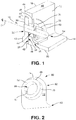
FIG. 1 is a partial sectional view of an exemplary casing flange joint with shoulder busing and bolt assembly; -
FIG. 2 is a rear perspective view of an exemplary shoulder bushing; and -
FIG. 3 is a perspective front view of the exemplary shoulder bushing ofFIG. 2 . - Referring now to
FIG. 1 , there is illustrated an exemplary embodiment of acoupling assembly 10 that may be used to fasten a pair ofcomponents components assembly 10 is not limited to being used withturbine casing components assembly 10 may be used to couple any adjacent components together. The specific size, shape, and configuration ofcoupling assembly 10, as described and/or illustrated herein, is exemplary only. Accordingly, the specific size, shape, and/or configuration ofcoupling assembly 10 generally, as well as portions thereof, may be selected to accommodate other components thanengine casing sections - In an exemplary embodiment, each
casing respective flange flange respective casing coupling assembly 10, eachflange respective casing coupling assembly 10 to function. - Each
casing flange first flange 16 andsecond flange 18. Each of thefirst flange 16 andsecond flange 18 includes abolt hole bolt 24 is inserted through eachflange bolt hole centerline 26. Thebolt 24 is securely fastened with anut 28. An optional washer orspacer 30 can be inserted over thebolt 24 and paired with thenut 28. - In an exemplary embodiment, casing 12 and 14 are annular structures; each
flange respective casing flange respective mating surface load bearing surface mating surface respective loading surface flange bolt hole respective mating surface load bearing surface - In an exemplary embodiment,
flange 16 has a generally rectangular cross-sectional profile and is formed such thatmating surface 32 extends from anend surface 40 offlange 16 to aninner surface 42 ofcasing 12. Moreover, in the exemplary embodiment,mating surface 32 is substantially parallel to load bearingsurface 36, andbolt hole 20 is oriented substantially perpendicularly tosurfaces mating surface 34 extends from anend surface 44 offlange 18 to aninner surface 46 ofcasing 14, and is substantially perpendicular to casing 14inner surface 46. -
Flange 14 is formed with anouter end portion 48, aninner end portion 50, and abody portion 52 extending integrally betweenouter end portion 48 andinner end portion 50. In an exemplary embodiment,flange body portion 52 has a substantially rectangular cross-sectional profile, and as such, withinflange body portion 52,load bearing surface 38 is substantially parallel tomating surface 34. - The
flange 18 includes a fillet orradius portion 54 in thebody portion 52 between theouter end portion 48 andinner end portion 50. Thefillet 54 forms the transition between thecasing 14 and theflange body portion 52. Thefillet 54 is opposite themating surface 34 and can form a portion of theload bearing surface 38. - Referring also to
FIG. 2 andFIG. 3 , thecoupling assembly 10 includes abushing 60.Bushing 60 can be a shoulder bushing having abody portion 62 forming abore 64 configured to receive thebolt 24, insertable through thebore 64. Thebore 64 is configured to align with thecenterline 26. - The
body portion 62 includes acylinder portion 66 that encircles thebore 64 and is configured to insert into thebolt hole 22 offlange 18. In an exemplary embodiment, thecylinder portion 66 can be interference fit into thebolt hole 22. Thecylinder portion 66 includes aninner diameter 68 andouter diameter 70. Theinner diameter 68 is configured to receive thebolt 24. Theouter diameter 70 is configured to insert into and abut thebolt hole 22.Cylinder portion 66 can be substantially cylindrical in shape. Thecylinder portion 66 includes aface 72 formed between theinner diameter 68 andouter diameter 70. Theface 72 can be a planar circular surface. Upon installation of thebushing 60, theface 72 can be located along the same plane as themating surface 34. Theface 72 serves to couple against themating surface 32 offlange 16 in addition to themating surface 34 of theflange 18 when thecoupling assembly 10 is in service. - The
body portion 62 includes aflange portion 74.Flange portion 74 of thebushing 60 extends from thecylinder portion 66 along a plane substantially perpendicular or orthogonal to thebore 64 and parallel with a plane of theface 72. In thecoupling assembly 10, theflange portion 74 abuts theload bearing surface 38 offlange 18 and functions to distribute the load across an area of theload bearing surface 38. Theflange portion 74 includes a bushinginner face 76 proximate thecylinder portion 66. The flange portion includes a bushingouter face 78 opposite the bushinginner face 76. The bushinginner face 76 is configured to abut theload bearing surface 38. Theouter face 78 is configured to abut at least one of thenut 28 and thewasher 30 or in alternative arrangements, a bolt head (not shown). - The
body portion 62 also includes alip portion 80. Thelip portion 80 is a curvilinear shape that matches the same shape of thefillet 54 of theflange 18 andcasing 14. Thelip portion 80 is integral to and adjoins theflange portion 74. Thelip portion 80 curves and extends from thecylinder portion 66 outward to alip end face 82. The lip end face 82 can be substantially parallel to the bushingouter face 78 and/or theface 72 of thecylinder portion 66. In another exemplary embodiment, thelip end face 82 is formed as a rectilinear surface. Thelip portion 80 extends from said cylinder portion such that thelip end face 82 is orthogonal to a portion of saidload bearing surface 38 proximate thecasing 14 beyond thefillet 54. Thelip portion 80 is configured to bear a portion of the load along thefillet 54 and parts of thecasing 14 proximate thefillet 54. Thelip portion 80 can include a varying thickness extending from thecylinder portion 66 outwardly to thelip end face 82. In an exemplary embodiment, thelip portion 80 can include a greater thickness than theflange portion 74. The thickness of theflange portion 74 and lip portion as well as theentire bushing 60 can vary depending on the size of thebolt hole flange bolt 24. In an exemplary embodiment the ratio of the thickness of thelip portion 80 to theflange portion 74 thickness is about 2 to 1. In an exemplary embodiment, the ratio of the thickness of thelip portion 80 thecase flange 18 thickness is about 3 to 1. Thelip portion 80 includes anouter radius 84 and aninner radius 86 opposite thereof. Theouter radius 84 matches the radius of thefillet 54. - The
lip portion 80 provides additional load bearing capacity for thebushing 60. Thelip portion 80 provides load bearing along afillet region 56 of theflange 18 andcasing 14. In an exemplary embodiment, thelip portion 80 can extend outwardly away from theouter face 78 about 3 times the diameter of thebolt hole 22. - In an exemplary embodiment, the
body portion 62 can include a reducedportion 88 located in the bushingouter face 78 proximate thebore 64. The reducedportion 88 of theouter face 78 is configured to abut at least one of thenut 28 and thewasher 30 or in alternative arrangements, a bolt head (not shown). Aledge 90 is formed in theouter face 78 proximate the reducedportion 88. Theledge 90 can be a curvilinear shape and match the shape of thecylinder portion 66 and be configured to receive thewasher 30 and/or thenut 28 or bolt head. Theledge 90 defines a region of greater thickness in thebushing body portion 62 than the relatively thinner reducedportion 88 of the bushingouter face 78. - The addition of the
lip portion 80 allows for more efficient load redistribution. The resultant load redistribution allows for a reduction in the thickness of thebushing 60. In an exemplary embodiment, the thickness requirement can be reduced from 0.07 inches to about 0.05 inches. - The novel shoulder bushing design redistributes the load to a bigger bolt hole after corrosion has been removed. The bearing load from the bolt concentrates at 6 o'clock of the bolt hole proximate the fillet region. The lip portion proximate to the 6 o'clock position provides the stiffness to redistribute the load tangentially away from the hole. Since the shape of the lip portion can be dependent upon the flange geometry, the lip portion thickness can vary.
- In an exemplary embodiment, the novel shoulder bushing design allows a thinner bushing 60 (e.g., 0.035") such that the existing
bolt 24 can still be used in theassembly 10. - The additional load bearing capacity of the
lip portion 80 allows for a morenarrow bushing 60 and allows thebolt 24 to remain a similar length to theoriginal bolt 24 length, thus eliminating the need to perform an additional Design Change, saving considerable expenses and design/repair/replacement schedule. - The novel shoulder bushing design eliminates the need to scrap the corroded fan case, as the corrosion gets worse. The new bushing design allows the repair of the expensive component and continued service.
- There has been provided a casing flange bushing. While the casing flange bushing has been described in the context of specific embodiments thereof, other unforeseen alternatives, modifications, and variations may become apparent to those skilled in the art having read the foregoing description. Accordingly, it is intended to embrace those alternatives, modifications, and variations which fall within the broad scope of the appended claims.
Claims (13)
- A casing flange coupling assembly (10) comprising:a first casing (12) comprising a first flange (16), said first flange (16) including at least one bolt hole (20) ;a second casing (14) coupled to said first casing (12), said second casing (14) comprising a second flange (18), said second flange (18) including at least one bolt hole (22) aligned with said first flange bolt hole (20);a bushing (60) coupled to said second flange (18), said bushing (60) comprising a body portion (62) including a cylinder portion (66) having a bore (64) configured to receive a bolt (24); a flange portion (74) orthogonal and integral to said cylinder portion (66), said flange portion (74) configured to couple with a load bearing surface (38) of said second flange (18); a lip portion (80) integral to said flange portion (74) proximate said cylinder portion (66), wherein said lip portion (80) redistributes a flange load; andsaid bolt (24) inserted through said bore (64) and said first flange (16) at least one bolt hole (20).
- The casing flange coupling assembly (10) according to claim 1, wherein said lip portion (80) comprises a curvilinear shape that matches a radius of a fillet (54) of said second flange (18).
- The casing flange coupling assembly (10) according to claim 2, wherein said lip portion (80) is configured to bear a portion of the flange load along the fillet (54) and parts of the casing (14) proximate a fillet region (58).
- The casing flange coupling assembly (10) according to claim 1 or 2, wherein said lip portion (80) extends from said cylinder portion (66) to a lip end face, said lip end face being adjacent to and orthogonal to a portion of said load bearing surface (38).
- The casing flange coupling assembly (10) according to claim 4, wherein said lip portion (80) comprises a varying thickness extending distally from said cylinder portion (66) to the lip end face.
- The casing flange coupling assembly (10) according to any preceding claim, wherein said bushing body portion (62) comprises a reduced portion (88) located in a bushing outer face (78) proximate said bore (64) opposite said cylinder portion (66).
- A method of redistributing a flange load for a repaired casing flange bolt hole (20) comprising:coupling a first casing flange (16) with a second casing flange (18);coupling a bushing (60) with said casing flange bolt hole (20), andredistributing a flange load with a lip portion (80) of said bushing (60).
- The process of claim 7, wherein said lip portion (80) comprises an outer radius (84) that matches a radius of a fillet (54) of said second flange (18).
- The process of claim 7 or 8, further comprising:bearing said flange load with said lip portion (80) along a fillet region (58) of said second flange (18) and a second casing (14).
- The process of claim 9, further comprising:varying a thickness of said lip portion (80) extending along said lip portion (80) proximate said fillet region (54).
- The process of any of claims 7 to 10, wherein said lip portion (80) and a thickness of said bushing (60) varies responsive to at least one of a diameter of a bolt (24) and a diameter of said casing flange bolt hole (20).
- The process of any of claims 7 to 11, further comprising:reducing the thickness of said bushing (60) to retain a flange bolt length equal to a flange bolt length prior to said flange repair.
- The process of claim 12, wherein said reducing step includes providing a reduced portion (88) located in said bushing (60) at an outer face (78) proximate a bore (64) of said bushing (60).
Applications Claiming Priority (1)
| Application Number | Priority Date | Filing Date | Title |
|---|---|---|---|
| US14/948,432 US10352328B2 (en) | 2015-11-23 | 2015-11-23 | Fan case bushing |
Publications (2)
| Publication Number | Publication Date |
|---|---|
| EP3170994A1 true EP3170994A1 (en) | 2017-05-24 |
| EP3170994B1 EP3170994B1 (en) | 2020-10-28 |
Family
ID=57396300
Family Applications (1)
| Application Number | Title | Priority Date | Filing Date |
|---|---|---|---|
| EP16200352.9A Active EP3170994B1 (en) | 2015-11-23 | 2016-11-23 | Casing flange coupling assembly and corresponding method of redistributing a flange load |
Country Status (3)
| Country | Link |
|---|---|
| US (2) | US10352328B2 (en) |
| EP (1) | EP3170994B1 (en) |
| SG (1) | SG10201609710VA (en) |
Cited By (1)
| Publication number | Priority date | Publication date | Assignee | Title |
|---|---|---|---|---|
| EP4174290A1 (en) * | 2021-10-29 | 2023-05-03 | Pratt & Whitney Canada Corp. | Support plate for engine casing flange |
Families Citing this family (3)
| Publication number | Priority date | Publication date | Assignee | Title |
|---|---|---|---|---|
| US10502235B2 (en) | 2013-11-06 | 2019-12-10 | United Technologies Corporation | Method for tight control of bolt holes in fan assembly |
| GB2569294A (en) * | 2017-12-08 | 2019-06-19 | Vestas Wind Sys As | Method of repairing a joint connecting a wind turbine rotor blade to a rotor hub |
| US10774685B2 (en) * | 2018-04-30 | 2020-09-15 | Ratheon Technologies Corporation | Gas turbine engine exhaust component |
Citations (1)
| Publication number | Priority date | Publication date | Assignee | Title |
|---|---|---|---|---|
| US20030118399A1 (en) * | 2001-12-21 | 2003-06-26 | Schilling Jan Christopher | Removable stud for joining casing flanges |
Family Cites Families (24)
| Publication number | Priority date | Publication date | Assignee | Title |
|---|---|---|---|---|
| US986506A (en) * | 1909-12-18 | 1911-03-14 | Olaf E Oleson | Process of coupling pipes. |
| US2477447A (en) * | 1943-08-16 | 1949-07-26 | Thomas L Fawick | Flexible coupling |
| US2565606A (en) * | 1946-10-09 | 1951-08-28 | Guy & Murton Inc | Universal joint |
| GB715086A (en) * | 1953-02-06 | 1954-09-08 | Rolls Royce | Improvements relating to separable joints |
| US2889396A (en) * | 1954-09-20 | 1959-06-02 | Westinghouse Electric Corp | Adjustable terminal-bushing mounting |
| US3235291A (en) * | 1963-04-29 | 1966-02-15 | Phillips Petroleum Co | Coupling for a thermoplastic liner in a metal conduit |
| US4540389A (en) * | 1983-04-01 | 1985-09-10 | Maxi-Lift, Inc. | Belt splicing device |
| US4721008A (en) * | 1986-03-03 | 1988-01-26 | American Motors Corporation | Adjustable steering wheel hub |
| US4953777A (en) | 1986-10-08 | 1990-09-04 | Chromalloy Gas Turbine Corporation | Method for repairing by solid state diffusion metal parts having damaged holes |
| US4830557A (en) * | 1988-01-26 | 1989-05-16 | General Electric Company | Self-aligning floating nut fastener |
| US5052891A (en) * | 1990-03-12 | 1991-10-01 | General Motors Corporation | Connection for gas turbine engine rotor elements |
| US6238131B1 (en) * | 1999-05-27 | 2001-05-29 | Deere & Company | Draper belt connector assembly for a harvesting machine |
| US6467988B1 (en) * | 2000-05-20 | 2002-10-22 | General Electric Company | Reducing cracking adjacent shell flange connecting bolts |
| US7094029B2 (en) * | 2003-05-06 | 2006-08-22 | General Electric Company | Methods and apparatus for controlling gas turbine engine rotor tip clearances |
| GB0321056D0 (en) * | 2003-09-09 | 2003-10-08 | Rolls Royce Plc | Joint arrangement |
| FR2889863B1 (en) * | 2005-08-22 | 2007-11-02 | Snecma | COMPRESSOR COMPRISING A PLURALITY OF HOUSINGS RECONSTITUTING AN ANNULAR VOLUME OF FLOW SEPARATION IN A TURBOMACHINE. |
| US8079773B2 (en) * | 2005-10-18 | 2011-12-20 | General Electric Company | Methods and apparatus for assembling composite structures |
| FR2922588B1 (en) | 2007-10-22 | 2013-11-01 | Snecma | DISC OR ROTOR DRUM OF A TURBOMACHINE |
| EP2321499B1 (en) * | 2008-08-29 | 2017-12-13 | GKN Aerospace Sweden AB | A component and a gas turbine engine comprising the component |
| FR2956054B1 (en) | 2010-02-10 | 2012-04-27 | Snecma | METHOD FOR REPAIRING A FLANGE OF A CARTER |
| FR2979385A1 (en) * | 2011-08-22 | 2013-03-01 | Snecma | ACOUSTIC INSULATION PANEL FOR TURBOMACHINE AND TURBOMACHINE COMPRISING SUCH A PANEL |
| US10221718B2 (en) * | 2013-09-09 | 2019-03-05 | United Technologies Corporation | Fan cases and manufacture methods |
| US9605730B2 (en) * | 2014-02-10 | 2017-03-28 | Maxi-Lift, Inc. | Adjustable elevator belt splice |
| US10502059B2 (en) * | 2015-02-02 | 2019-12-10 | United Technologies Corporation | Alignment tie rod device and method of utilization |
-
2015
- 2015-11-23 US US14/948,432 patent/US10352328B2/en active Active
-
2016
- 2016-11-18 SG SG10201609710VA patent/SG10201609710VA/en unknown
- 2016-11-23 EP EP16200352.9A patent/EP3170994B1/en active Active
-
2019
- 2019-06-24 US US16/449,815 patent/US10648478B2/en active Active
Patent Citations (1)
| Publication number | Priority date | Publication date | Assignee | Title |
|---|---|---|---|---|
| US20030118399A1 (en) * | 2001-12-21 | 2003-06-26 | Schilling Jan Christopher | Removable stud for joining casing flanges |
Cited By (2)
| Publication number | Priority date | Publication date | Assignee | Title |
|---|---|---|---|---|
| EP4174290A1 (en) * | 2021-10-29 | 2023-05-03 | Pratt & Whitney Canada Corp. | Support plate for engine casing flange |
| US12006832B2 (en) | 2021-10-29 | 2024-06-11 | Pratt & Whitney Canada Corp. | Support plate for engine casing flange |
Also Published As
| Publication number | Publication date |
|---|---|
| US10648478B2 (en) | 2020-05-12 |
| US10352328B2 (en) | 2019-07-16 |
| SG10201609710VA (en) | 2017-06-29 |
| EP3170994B1 (en) | 2020-10-28 |
| US20190309764A1 (en) | 2019-10-10 |
| US20170146018A1 (en) | 2017-05-25 |
Similar Documents
| Publication | Publication Date | Title |
|---|---|---|
| US10648478B2 (en) | Fan case bushing | |
| CN102057200B (en) | There is the flange assembly of the use ability of improvement | |
| US6390720B1 (en) | Method and apparatus for connecting a tube to a machine | |
| US20070289351A1 (en) | Wave relieving geometric features in structural members that are radially expandable into workpieces | |
| US8262331B2 (en) | Integrated expanding sleeve hole filling threaded fastener | |
| US8864472B2 (en) | Method of repairing or reworking a turbomachine disk and repaired or reworked turbomachine disk | |
| US8028414B2 (en) | Engine mount bearing sleeve repair | |
| EP1779964A1 (en) | Radially displaceable bushing for retaining a member relative to a structural workpiece | |
| US4778342A (en) | Turbine blade retainer | |
| US20100272383A1 (en) | Split locking sleeve | |
| US9028210B2 (en) | Turbomachine alignment pin | |
| EP3192981A1 (en) | Fan case assembly | |
| EP2612043B1 (en) | Locking nut assembly | |
| US8529177B2 (en) | Integrated pin/sleeve blind fastener | |
| US7761991B2 (en) | Methods and apparatus for coupling gas turbine engine components | |
| US6186452B1 (en) | Robust tube strap clamp | |
| US7845076B2 (en) | Method for reducing stresses resulting from partial slot dovetail re-machining for generator rotor | |
| US20150105212A1 (en) | System and method for salvaging a pin-bore assembly | |
| US10731492B2 (en) | Component joint | |
| CN105308332A (en) | Fan discs for jet engines and jet engines | |
| US4797065A (en) | Turbine blade retainer | |
| US8734103B2 (en) | Method of repairing a flange of a casing | |
| RU2169876C2 (en) | Flanged joint unit | |
| US8430627B2 (en) | Gas turbine exhaust strut refurbishment | |
| US20180149110A1 (en) | Apparatus and method of use of apparatus for locating components of a system |
Legal Events
| Date | Code | Title | Description |
|---|---|---|---|
| PUAI | Public reference made under article 153(3) epc to a published international application that has entered the european phase |
Free format text: ORIGINAL CODE: 0009012 |
|
| STAA | Information on the status of an ep patent application or granted ep patent |
Free format text: STATUS: THE APPLICATION HAS BEEN PUBLISHED |
|
| AK | Designated contracting states |
Kind code of ref document: A1 Designated state(s): AL AT BE BG CH CY CZ DE DK EE ES FI FR GB GR HR HU IE IS IT LI LT LU LV MC MK MT NL NO PL PT RO RS SE SI SK SM TR |
|
| AX | Request for extension of the european patent |
Extension state: BA ME |
|
| STAA | Information on the status of an ep patent application or granted ep patent |
Free format text: STATUS: REQUEST FOR EXAMINATION WAS MADE |
|
| 17P | Request for examination filed |
Effective date: 20171124 |
|
| RBV | Designated contracting states (corrected) |
Designated state(s): AL AT BE BG CH CY CZ DE DK EE ES FI FR GB GR HR HU IE IS IT LI LT LU LV MC MK MT NL NO PL PT RO RS SE SI SK SM TR |
|
| STAA | Information on the status of an ep patent application or granted ep patent |
Free format text: STATUS: EXAMINATION IS IN PROGRESS |
|
| 17Q | First examination report despatched |
Effective date: 20180730 |
|
| GRAP | Despatch of communication of intention to grant a patent |
Free format text: ORIGINAL CODE: EPIDOSNIGR1 |
|
| STAA | Information on the status of an ep patent application or granted ep patent |
Free format text: STATUS: GRANT OF PATENT IS INTENDED |
|
| RIC1 | Information provided on ipc code assigned before grant |
Ipc: F04D 29/52 20060101ALI20200408BHEP Ipc: F04D 29/64 20060101ALI20200408BHEP Ipc: F01D 25/24 20060101AFI20200408BHEP |
|
| INTG | Intention to grant announced |
Effective date: 20200507 |
|
| GRAS | Grant fee paid |
Free format text: ORIGINAL CODE: EPIDOSNIGR3 |
|
| GRAA | (expected) grant |
Free format text: ORIGINAL CODE: 0009210 |
|
| STAA | Information on the status of an ep patent application or granted ep patent |
Free format text: STATUS: THE PATENT HAS BEEN GRANTED |
|
| AK | Designated contracting states |
Kind code of ref document: B1 Designated state(s): AL AT BE BG CH CY CZ DE DK EE ES FI FR GB GR HR HU IE IS IT LI LT LU LV MC MK MT NL NO PL PT RO RS SE SI SK SM TR |
|
| REG | Reference to a national code |
Ref country code: GB Ref legal event code: FG4D |
|
| REG | Reference to a national code |
Ref country code: CH Ref legal event code: EP |
|
| REG | Reference to a national code |
Ref country code: AT Ref legal event code: REF Ref document number: 1328444 Country of ref document: AT Kind code of ref document: T Effective date: 20201115 |
|
| REG | Reference to a national code |
Ref country code: DE Ref legal event code: R096 Ref document number: 602016046613 Country of ref document: DE |
|
| REG | Reference to a national code |
Ref country code: IE Ref legal event code: FG4D |
|
| REG | Reference to a national code |
Ref country code: AT Ref legal event code: MK05 Ref document number: 1328444 Country of ref document: AT Kind code of ref document: T Effective date: 20201028 |
|
| RAP2 | Party data changed (patent owner data changed or rights of a patent transferred) |
Owner name: RAYTHEON TECHNOLOGIES CORPORATION |
|
| REG | Reference to a national code |
Ref country code: NL Ref legal event code: MP Effective date: 20201028 |
|
| PG25 | Lapsed in a contracting state [announced via postgrant information from national office to epo] |
Ref country code: FI Free format text: LAPSE BECAUSE OF FAILURE TO SUBMIT A TRANSLATION OF THE DESCRIPTION OR TO PAY THE FEE WITHIN THE PRESCRIBED TIME-LIMIT Effective date: 20201028 Ref country code: GR Free format text: LAPSE BECAUSE OF FAILURE TO SUBMIT A TRANSLATION OF THE DESCRIPTION OR TO PAY THE FEE WITHIN THE PRESCRIBED TIME-LIMIT Effective date: 20210129 Ref country code: NO Free format text: LAPSE BECAUSE OF FAILURE TO SUBMIT A TRANSLATION OF THE DESCRIPTION OR TO PAY THE FEE WITHIN THE PRESCRIBED TIME-LIMIT Effective date: 20210128 Ref country code: NL Free format text: LAPSE BECAUSE OF FAILURE TO SUBMIT A TRANSLATION OF THE DESCRIPTION OR TO PAY THE FEE WITHIN THE PRESCRIBED TIME-LIMIT Effective date: 20201028 Ref country code: RS Free format text: LAPSE BECAUSE OF FAILURE TO SUBMIT A TRANSLATION OF THE DESCRIPTION OR TO PAY THE FEE WITHIN THE PRESCRIBED TIME-LIMIT Effective date: 20201028 Ref country code: PT Free format text: LAPSE BECAUSE OF FAILURE TO SUBMIT A TRANSLATION OF THE DESCRIPTION OR TO PAY THE FEE WITHIN THE PRESCRIBED TIME-LIMIT Effective date: 20210301 |
|
| REG | Reference to a national code |
Ref country code: LT Ref legal event code: MG4D |
|
| PG25 | Lapsed in a contracting state [announced via postgrant information from national office to epo] |
Ref country code: ES Free format text: LAPSE BECAUSE OF FAILURE TO SUBMIT A TRANSLATION OF THE DESCRIPTION OR TO PAY THE FEE WITHIN THE PRESCRIBED TIME-LIMIT Effective date: 20201028 Ref country code: AT Free format text: LAPSE BECAUSE OF FAILURE TO SUBMIT A TRANSLATION OF THE DESCRIPTION OR TO PAY THE FEE WITHIN THE PRESCRIBED TIME-LIMIT Effective date: 20201028 Ref country code: LV Free format text: LAPSE BECAUSE OF FAILURE TO SUBMIT A TRANSLATION OF THE DESCRIPTION OR TO PAY THE FEE WITHIN THE PRESCRIBED TIME-LIMIT Effective date: 20201028 Ref country code: PL Free format text: LAPSE BECAUSE OF FAILURE TO SUBMIT A TRANSLATION OF THE DESCRIPTION OR TO PAY THE FEE WITHIN THE PRESCRIBED TIME-LIMIT Effective date: 20201028 Ref country code: IS Free format text: LAPSE BECAUSE OF FAILURE TO SUBMIT A TRANSLATION OF THE DESCRIPTION OR TO PAY THE FEE WITHIN THE PRESCRIBED TIME-LIMIT Effective date: 20210228 Ref country code: BG Free format text: LAPSE BECAUSE OF FAILURE TO SUBMIT A TRANSLATION OF THE DESCRIPTION OR TO PAY THE FEE WITHIN THE PRESCRIBED TIME-LIMIT Effective date: 20210128 Ref country code: SE Free format text: LAPSE BECAUSE OF FAILURE TO SUBMIT A TRANSLATION OF THE DESCRIPTION OR TO PAY THE FEE WITHIN THE PRESCRIBED TIME-LIMIT Effective date: 20201028 |
|
| PG25 | Lapsed in a contracting state [announced via postgrant information from national office to epo] |
Ref country code: HR Free format text: LAPSE BECAUSE OF FAILURE TO SUBMIT A TRANSLATION OF THE DESCRIPTION OR TO PAY THE FEE WITHIN THE PRESCRIBED TIME-LIMIT Effective date: 20201028 |
|
| REG | Reference to a national code |
Ref country code: CH Ref legal event code: PL |
|
| REG | Reference to a national code |
Ref country code: DE Ref legal event code: R097 Ref document number: 602016046613 Country of ref document: DE |
|
| PG25 | Lapsed in a contracting state [announced via postgrant information from national office to epo] |
Ref country code: LU Free format text: LAPSE BECAUSE OF NON-PAYMENT OF DUE FEES Effective date: 20201123 Ref country code: MC Free format text: LAPSE BECAUSE OF FAILURE TO SUBMIT A TRANSLATION OF THE DESCRIPTION OR TO PAY THE FEE WITHIN THE PRESCRIBED TIME-LIMIT Effective date: 20201028 Ref country code: LT Free format text: LAPSE BECAUSE OF FAILURE TO SUBMIT A TRANSLATION OF THE DESCRIPTION OR TO PAY THE FEE WITHIN THE PRESCRIBED TIME-LIMIT Effective date: 20201028 Ref country code: SM Free format text: LAPSE BECAUSE OF FAILURE TO SUBMIT A TRANSLATION OF THE DESCRIPTION OR TO PAY THE FEE WITHIN THE PRESCRIBED TIME-LIMIT Effective date: 20201028 Ref country code: CZ Free format text: LAPSE BECAUSE OF FAILURE TO SUBMIT A TRANSLATION OF THE DESCRIPTION OR TO PAY THE FEE WITHIN THE PRESCRIBED TIME-LIMIT Effective date: 20201028 Ref country code: EE Free format text: LAPSE BECAUSE OF FAILURE TO SUBMIT A TRANSLATION OF THE DESCRIPTION OR TO PAY THE FEE WITHIN THE PRESCRIBED TIME-LIMIT Effective date: 20201028 Ref country code: RO Free format text: LAPSE BECAUSE OF FAILURE TO SUBMIT A TRANSLATION OF THE DESCRIPTION OR TO PAY THE FEE WITHIN THE PRESCRIBED TIME-LIMIT Effective date: 20201028 Ref country code: SK Free format text: LAPSE BECAUSE OF FAILURE TO SUBMIT A TRANSLATION OF THE DESCRIPTION OR TO PAY THE FEE WITHIN THE PRESCRIBED TIME-LIMIT Effective date: 20201028 |
|
| REG | Reference to a national code |
Ref country code: BE Ref legal event code: MM Effective date: 20201130 |
|
| PG25 | Lapsed in a contracting state [announced via postgrant information from national office to epo] |
Ref country code: LI Free format text: LAPSE BECAUSE OF NON-PAYMENT OF DUE FEES Effective date: 20201130 Ref country code: CH Free format text: LAPSE BECAUSE OF NON-PAYMENT OF DUE FEES Effective date: 20201130 Ref country code: DK Free format text: LAPSE BECAUSE OF FAILURE TO SUBMIT A TRANSLATION OF THE DESCRIPTION OR TO PAY THE FEE WITHIN THE PRESCRIBED TIME-LIMIT Effective date: 20201028 |
|
| PLBE | No opposition filed within time limit |
Free format text: ORIGINAL CODE: 0009261 |
|
| STAA | Information on the status of an ep patent application or granted ep patent |
Free format text: STATUS: NO OPPOSITION FILED WITHIN TIME LIMIT |
|
| 26N | No opposition filed |
Effective date: 20210729 |
|
| PG25 | Lapsed in a contracting state [announced via postgrant information from national office to epo] |
Ref country code: AL Free format text: LAPSE BECAUSE OF FAILURE TO SUBMIT A TRANSLATION OF THE DESCRIPTION OR TO PAY THE FEE WITHIN THE PRESCRIBED TIME-LIMIT Effective date: 20201028 Ref country code: IT Free format text: LAPSE BECAUSE OF FAILURE TO SUBMIT A TRANSLATION OF THE DESCRIPTION OR TO PAY THE FEE WITHIN THE PRESCRIBED TIME-LIMIT Effective date: 20201028 Ref country code: IE Free format text: LAPSE BECAUSE OF NON-PAYMENT OF DUE FEES Effective date: 20201123 |
|
| PG25 | Lapsed in a contracting state [announced via postgrant information from national office to epo] |
Ref country code: SI Free format text: LAPSE BECAUSE OF FAILURE TO SUBMIT A TRANSLATION OF THE DESCRIPTION OR TO PAY THE FEE WITHIN THE PRESCRIBED TIME-LIMIT Effective date: 20201028 |
|
| PG25 | Lapsed in a contracting state [announced via postgrant information from national office to epo] |
Ref country code: IS Free format text: LAPSE BECAUSE OF FAILURE TO SUBMIT A TRANSLATION OF THE DESCRIPTION OR TO PAY THE FEE WITHIN THE PRESCRIBED TIME-LIMIT Effective date: 20210228 Ref country code: TR Free format text: LAPSE BECAUSE OF FAILURE TO SUBMIT A TRANSLATION OF THE DESCRIPTION OR TO PAY THE FEE WITHIN THE PRESCRIBED TIME-LIMIT Effective date: 20201028 Ref country code: MT Free format text: LAPSE BECAUSE OF FAILURE TO SUBMIT A TRANSLATION OF THE DESCRIPTION OR TO PAY THE FEE WITHIN THE PRESCRIBED TIME-LIMIT Effective date: 20201028 Ref country code: CY Free format text: LAPSE BECAUSE OF FAILURE TO SUBMIT A TRANSLATION OF THE DESCRIPTION OR TO PAY THE FEE WITHIN THE PRESCRIBED TIME-LIMIT Effective date: 20201028 |
|
| PG25 | Lapsed in a contracting state [announced via postgrant information from national office to epo] |
Ref country code: MK Free format text: LAPSE BECAUSE OF FAILURE TO SUBMIT A TRANSLATION OF THE DESCRIPTION OR TO PAY THE FEE WITHIN THE PRESCRIBED TIME-LIMIT Effective date: 20201028 |
|
| PG25 | Lapsed in a contracting state [announced via postgrant information from national office to epo] |
Ref country code: BE Free format text: LAPSE BECAUSE OF NON-PAYMENT OF DUE FEES Effective date: 20201130 |
|
| P01 | Opt-out of the competence of the unified patent court (upc) registered |
Effective date: 20230520 |
|
| REG | Reference to a national code |
Ref country code: DE Ref legal event code: R081 Ref document number: 602016046613 Country of ref document: DE Owner name: RTX CORPORATION (N.D.GES.D. STAATES DELAWARE),, US Free format text: FORMER OWNER: UNITED TECHNOLOGIES CORPORATION, FARMINGTON, CONN., US |
|
| PGFP | Annual fee paid to national office [announced via postgrant information from national office to epo] |
Ref country code: DE Payment date: 20251022 Year of fee payment: 10 |
|
| PGFP | Annual fee paid to national office [announced via postgrant information from national office to epo] |
Ref country code: GB Payment date: 20251023 Year of fee payment: 10 |
|
| PGFP | Annual fee paid to national office [announced via postgrant information from national office to epo] |
Ref country code: FR Payment date: 20251022 Year of fee payment: 10 |