EP3170989A1 - Grooved seal arrangement for turbine engine - Google Patents
Grooved seal arrangement for turbine engine Download PDFInfo
- Publication number
- EP3170989A1 EP3170989A1 EP16199689.7A EP16199689A EP3170989A1 EP 3170989 A1 EP3170989 A1 EP 3170989A1 EP 16199689 A EP16199689 A EP 16199689A EP 3170989 A1 EP3170989 A1 EP 3170989A1
- Authority
- EP
- European Patent Office
- Prior art keywords
- grooves
- seal
- seal member
- recited
- cold side
- Prior art date
- Legal status (The legal status is an assumption and is not a legal conclusion. Google has not performed a legal analysis and makes no representation as to the accuracy of the status listed.)
- Granted
Links
- 238000001816 cooling Methods 0.000 claims abstract description 66
- 210000003746 feather Anatomy 0.000 claims description 10
- 238000000034 method Methods 0.000 claims description 9
- 239000002826 coolant Substances 0.000 claims description 7
- 238000007789 sealing Methods 0.000 claims description 6
- 238000004891 communication Methods 0.000 claims description 4
- 230000004044 response Effects 0.000 claims description 3
- 241000283216 Phocidae Species 0.000 description 14
- 239000007789 gas Substances 0.000 description 12
- 239000012530 fluid Substances 0.000 description 6
- 239000000446 fuel Substances 0.000 description 5
- PXHVJJICTQNCMI-UHFFFAOYSA-N Nickel Chemical compound [Ni] PXHVJJICTQNCMI-UHFFFAOYSA-N 0.000 description 3
- 230000008901 benefit Effects 0.000 description 3
- 238000002485 combustion reaction Methods 0.000 description 3
- 230000003068 static effect Effects 0.000 description 3
- 238000011144 upstream manufacturing Methods 0.000 description 3
- 230000003416 augmentation Effects 0.000 description 2
- 229910017052 cobalt Inorganic materials 0.000 description 2
- 239000010941 cobalt Substances 0.000 description 2
- GUTLYIVDDKVIGB-UHFFFAOYSA-N cobalt atom Chemical compound [Co] GUTLYIVDDKVIGB-UHFFFAOYSA-N 0.000 description 2
- 239000000567 combustion gas Substances 0.000 description 2
- 230000009467 reduction Effects 0.000 description 2
- 239000000654 additive Substances 0.000 description 1
- 230000000996 additive effect Effects 0.000 description 1
- 239000000956 alloy Substances 0.000 description 1
- 229910045601 alloy Inorganic materials 0.000 description 1
- WYTGDNHDOZPMIW-RCBQFDQVSA-N alstonine Natural products C1=CC2=C3C=CC=CC3=NC2=C2N1C[C@H]1[C@H](C)OC=C(C(=O)OC)[C@H]1C2 WYTGDNHDOZPMIW-RCBQFDQVSA-N 0.000 description 1
- 230000015556 catabolic process Effects 0.000 description 1
- 230000008859 change Effects 0.000 description 1
- 239000002131 composite material Substances 0.000 description 1
- 230000006835 compression Effects 0.000 description 1
- 238000007906 compression Methods 0.000 description 1
- 238000006731 degradation reaction Methods 0.000 description 1
- 230000037406 food intake Effects 0.000 description 1
- 238000004519 manufacturing process Methods 0.000 description 1
- 239000000463 material Substances 0.000 description 1
- 230000007246 mechanism Effects 0.000 description 1
- 239000002184 metal Substances 0.000 description 1
- 229910052751 metal Inorganic materials 0.000 description 1
- 238000012986 modification Methods 0.000 description 1
- 230000004048 modification Effects 0.000 description 1
- 229910052759 nickel Inorganic materials 0.000 description 1
Images

Classifications
-
- F—MECHANICAL ENGINEERING; LIGHTING; HEATING; WEAPONS; BLASTING
- F01—MACHINES OR ENGINES IN GENERAL; ENGINE PLANTS IN GENERAL; STEAM ENGINES
- F01D—NON-POSITIVE DISPLACEMENT MACHINES OR ENGINES, e.g. STEAM TURBINES
- F01D5/00—Blades; Blade-carrying members; Heating, heat-insulating, cooling or antivibration means on the blades or the members
- F01D5/12—Blades
- F01D5/22—Blade-to-blade connections, e.g. for damping vibrations
-
- F—MECHANICAL ENGINEERING; LIGHTING; HEATING; WEAPONS; BLASTING
- F01—MACHINES OR ENGINES IN GENERAL; ENGINE PLANTS IN GENERAL; STEAM ENGINES
- F01D—NON-POSITIVE DISPLACEMENT MACHINES OR ENGINES, e.g. STEAM TURBINES
- F01D11/00—Preventing or minimising internal leakage of working-fluid, e.g. between stages
- F01D11/005—Sealing means between non relatively rotating elements
-
- F—MECHANICAL ENGINEERING; LIGHTING; HEATING; WEAPONS; BLASTING
- F01—MACHINES OR ENGINES IN GENERAL; ENGINE PLANTS IN GENERAL; STEAM ENGINES
- F01D—NON-POSITIVE DISPLACEMENT MACHINES OR ENGINES, e.g. STEAM TURBINES
- F01D11/00—Preventing or minimising internal leakage of working-fluid, e.g. between stages
- F01D11/005—Sealing means between non relatively rotating elements
- F01D11/006—Sealing the gap between rotor blades or blades and rotor
-
- F—MECHANICAL ENGINEERING; LIGHTING; HEATING; WEAPONS; BLASTING
- F01—MACHINES OR ENGINES IN GENERAL; ENGINE PLANTS IN GENERAL; STEAM ENGINES
- F01D—NON-POSITIVE DISPLACEMENT MACHINES OR ENGINES, e.g. STEAM TURBINES
- F01D11/00—Preventing or minimising internal leakage of working-fluid, e.g. between stages
- F01D11/005—Sealing means between non relatively rotating elements
- F01D11/006—Sealing the gap between rotor blades or blades and rotor
- F01D11/008—Sealing the gap between rotor blades or blades and rotor by spacer elements between the blades, e.g. independent interblade platforms
-
- F—MECHANICAL ENGINEERING; LIGHTING; HEATING; WEAPONS; BLASTING
- F01—MACHINES OR ENGINES IN GENERAL; ENGINE PLANTS IN GENERAL; STEAM ENGINES
- F01D—NON-POSITIVE DISPLACEMENT MACHINES OR ENGINES, e.g. STEAM TURBINES
- F01D25/00—Component parts, details, or accessories, not provided for in, or of interest apart from, other groups
- F01D25/08—Cooling; Heating; Heat-insulation
- F01D25/12—Cooling
-
- F—MECHANICAL ENGINEERING; LIGHTING; HEATING; WEAPONS; BLASTING
- F16—ENGINEERING ELEMENTS AND UNITS; GENERAL MEASURES FOR PRODUCING AND MAINTAINING EFFECTIVE FUNCTIONING OF MACHINES OR INSTALLATIONS; THERMAL INSULATION IN GENERAL
- F16J—PISTONS; CYLINDERS; SEALINGS
- F16J15/00—Sealings
- F16J15/16—Sealings between relatively-moving surfaces
- F16J15/162—Special parts or details relating to lubrication or cooling of the sealing itself
-
- F—MECHANICAL ENGINEERING; LIGHTING; HEATING; WEAPONS; BLASTING
- F01—MACHINES OR ENGINES IN GENERAL; ENGINE PLANTS IN GENERAL; STEAM ENGINES
- F01D—NON-POSITIVE DISPLACEMENT MACHINES OR ENGINES, e.g. STEAM TURBINES
- F01D11/00—Preventing or minimising internal leakage of working-fluid, e.g. between stages
- F01D11/08—Preventing or minimising internal leakage of working-fluid, e.g. between stages for sealing space between rotor blade tips and stator
-
- F—MECHANICAL ENGINEERING; LIGHTING; HEATING; WEAPONS; BLASTING
- F01—MACHINES OR ENGINES IN GENERAL; ENGINE PLANTS IN GENERAL; STEAM ENGINES
- F01D—NON-POSITIVE DISPLACEMENT MACHINES OR ENGINES, e.g. STEAM TURBINES
- F01D25/00—Component parts, details, or accessories, not provided for in, or of interest apart from, other groups
- F01D25/04—Antivibration arrangements
- F01D25/06—Antivibration arrangements for preventing blade vibration
-
- F—MECHANICAL ENGINEERING; LIGHTING; HEATING; WEAPONS; BLASTING
- F01—MACHINES OR ENGINES IN GENERAL; ENGINE PLANTS IN GENERAL; STEAM ENGINES
- F01D—NON-POSITIVE DISPLACEMENT MACHINES OR ENGINES, e.g. STEAM TURBINES
- F01D5/00—Blades; Blade-carrying members; Heating, heat-insulating, cooling or antivibration means on the blades or the members
- F01D5/02—Blade-carrying members, e.g. rotors
- F01D5/08—Heating, heat-insulating or cooling means
- F01D5/081—Cooling fluid being directed on the side of the rotor disc or at the roots of the blades
-
- F—MECHANICAL ENGINEERING; LIGHTING; HEATING; WEAPONS; BLASTING
- F01—MACHINES OR ENGINES IN GENERAL; ENGINE PLANTS IN GENERAL; STEAM ENGINES
- F01D—NON-POSITIVE DISPLACEMENT MACHINES OR ENGINES, e.g. STEAM TURBINES
- F01D5/00—Blades; Blade-carrying members; Heating, heat-insulating, cooling or antivibration means on the blades or the members
- F01D5/02—Blade-carrying members, e.g. rotors
- F01D5/10—Anti- vibration means
-
- F—MECHANICAL ENGINEERING; LIGHTING; HEATING; WEAPONS; BLASTING
- F01—MACHINES OR ENGINES IN GENERAL; ENGINE PLANTS IN GENERAL; STEAM ENGINES
- F01D—NON-POSITIVE DISPLACEMENT MACHINES OR ENGINES, e.g. STEAM TURBINES
- F01D5/00—Blades; Blade-carrying members; Heating, heat-insulating, cooling or antivibration means on the blades or the members
- F01D5/30—Fixing blades to rotors; Blade roots ; Blade spacers
- F01D5/3007—Fixing blades to rotors; Blade roots ; Blade spacers of axial insertion type
-
- F—MECHANICAL ENGINEERING; LIGHTING; HEATING; WEAPONS; BLASTING
- F05—INDEXING SCHEMES RELATING TO ENGINES OR PUMPS IN VARIOUS SUBCLASSES OF CLASSES F01-F04
- F05D—INDEXING SCHEME FOR ASPECTS RELATING TO NON-POSITIVE-DISPLACEMENT MACHINES OR ENGINES, GAS-TURBINES OR JET-PROPULSION PLANTS
- F05D2220/00—Application
- F05D2220/30—Application in turbines
- F05D2220/32—Application in turbines in gas turbines
-
- F—MECHANICAL ENGINEERING; LIGHTING; HEATING; WEAPONS; BLASTING
- F05—INDEXING SCHEMES RELATING TO ENGINES OR PUMPS IN VARIOUS SUBCLASSES OF CLASSES F01-F04
- F05D—INDEXING SCHEME FOR ASPECTS RELATING TO NON-POSITIVE-DISPLACEMENT MACHINES OR ENGINES, GAS-TURBINES OR JET-PROPULSION PLANTS
- F05D2230/00—Manufacture
- F05D2230/60—Assembly methods
-
- F—MECHANICAL ENGINEERING; LIGHTING; HEATING; WEAPONS; BLASTING
- F05—INDEXING SCHEMES RELATING TO ENGINES OR PUMPS IN VARIOUS SUBCLASSES OF CLASSES F01-F04
- F05D—INDEXING SCHEME FOR ASPECTS RELATING TO NON-POSITIVE-DISPLACEMENT MACHINES OR ENGINES, GAS-TURBINES OR JET-PROPULSION PLANTS
- F05D2240/00—Components
- F05D2240/10—Stators
- F05D2240/12—Fluid guiding means, e.g. vanes
-
- F—MECHANICAL ENGINEERING; LIGHTING; HEATING; WEAPONS; BLASTING
- F05—INDEXING SCHEMES RELATING TO ENGINES OR PUMPS IN VARIOUS SUBCLASSES OF CLASSES F01-F04
- F05D—INDEXING SCHEME FOR ASPECTS RELATING TO NON-POSITIVE-DISPLACEMENT MACHINES OR ENGINES, GAS-TURBINES OR JET-PROPULSION PLANTS
- F05D2240/00—Components
- F05D2240/20—Rotors
- F05D2240/30—Characteristics of rotor blades, i.e. of any element transforming dynamic fluid energy to or from rotational energy and being attached to a rotor
- F05D2240/307—Characteristics of rotor blades, i.e. of any element transforming dynamic fluid energy to or from rotational energy and being attached to a rotor related to the tip of a rotor blade
-
- F—MECHANICAL ENGINEERING; LIGHTING; HEATING; WEAPONS; BLASTING
- F05—INDEXING SCHEMES RELATING TO ENGINES OR PUMPS IN VARIOUS SUBCLASSES OF CLASSES F01-F04
- F05D—INDEXING SCHEME FOR ASPECTS RELATING TO NON-POSITIVE-DISPLACEMENT MACHINES OR ENGINES, GAS-TURBINES OR JET-PROPULSION PLANTS
- F05D2240/00—Components
- F05D2240/55—Seals
-
- F—MECHANICAL ENGINEERING; LIGHTING; HEATING; WEAPONS; BLASTING
- F05—INDEXING SCHEMES RELATING TO ENGINES OR PUMPS IN VARIOUS SUBCLASSES OF CLASSES F01-F04
- F05D—INDEXING SCHEME FOR ASPECTS RELATING TO NON-POSITIVE-DISPLACEMENT MACHINES OR ENGINES, GAS-TURBINES OR JET-PROPULSION PLANTS
- F05D2240/00—Components
- F05D2240/80—Platforms for stationary or moving blades
- F05D2240/81—Cooled platforms
-
- F—MECHANICAL ENGINEERING; LIGHTING; HEATING; WEAPONS; BLASTING
- F05—INDEXING SCHEMES RELATING TO ENGINES OR PUMPS IN VARIOUS SUBCLASSES OF CLASSES F01-F04
- F05D—INDEXING SCHEME FOR ASPECTS RELATING TO NON-POSITIVE-DISPLACEMENT MACHINES OR ENGINES, GAS-TURBINES OR JET-PROPULSION PLANTS
- F05D2250/00—Geometry
- F05D2250/20—Three-dimensional
- F05D2250/29—Three-dimensional machined; miscellaneous
- F05D2250/294—Three-dimensional machined; miscellaneous grooved
-
- Y—GENERAL TAGGING OF NEW TECHNOLOGICAL DEVELOPMENTS; GENERAL TAGGING OF CROSS-SECTIONAL TECHNOLOGIES SPANNING OVER SEVERAL SECTIONS OF THE IPC; TECHNICAL SUBJECTS COVERED BY FORMER USPC CROSS-REFERENCE ART COLLECTIONS [XRACs] AND DIGESTS
- Y02—TECHNOLOGIES OR APPLICATIONS FOR MITIGATION OR ADAPTATION AGAINST CLIMATE CHANGE
- Y02T—CLIMATE CHANGE MITIGATION TECHNOLOGIES RELATED TO TRANSPORTATION
- Y02T50/00—Aeronautics or air transport
- Y02T50/60—Efficient propulsion technologies, e.g. for aircraft
Definitions
- This disclosure relates to cooling for a component of a gas turbine engine, and more particularly to a seal having one or more grooves for cooling augmentation.
- a seal arrangement for a gas turbine engine includes a component including a body having a cold side surface adjacent to a mate face, and a seal member including a leading edge region and a trailing edge region spaced by sidewalls.
- the seal member defines one or more grooves.
- the one or more grooves abut the cold side surface to define one or more cooling passages, with at least one of the one or more cooling passages having a flared inlet defined by a corresponding one of the one or more grooves.
- each of the one or more cooling passages has a flared inlet.
- the flared inlet is located along one of the sidewalls or the leading edge region.
- At least some of the one or more grooves includes a second end adjacent to the mate face. The second end is opposite to a first end defining the corresponding flared inlet.
- the second end of at least some of the grooves are spaced from each of the sidewalls.
- the cold side surface is located at a slot extending inwardly from the mate face, and the slot is configured to receive the seal member.
- At least some of the one or more grooves have a curved profile.
- the component is an airfoil.
- the airfoil includes an airfoil section extending from a platform, and the first cold side surface is located at the platform.
- a gas turbine engine includes a first component and a second component arranged about an axis.
- the first component includes a first cold side surface adjacent to a first mate face.
- the second component includes a second cold side surface adjacent to a second mate face.
- the first and second mate faces are arranged to define a leakage gap.
- a seal member defines a plurality of grooves adjacent to the leakage gap. The plurality of grooves abut the first and second cold side surfaces to define a plurality of cooling passages in communication with the leakage gap.
- One or more of the plurality of cooling passages has a flared inlet and an outlet adjacent to the leakage gap.
- the first cold side surface is located at a slot extending inwardly from the first mate face, and the slot is configured to receive the seal member.
- the seal member is moveable between a first position and a second position relative to the first component, and the outlet of at least some of the plurality of cooling passages are spaced from the sidewalls when the seal member is in the first and second positions.
- the flared inlet of one or more of the plurality of passages are spaced from the sidewalls.
- the first components is an airfoil.
- the airfoil includes an airfoil section extending from a platform.
- the platform includes an upper surface bounding a core flow path and an undersurface bounding a cooling cavity, and the first cold side surface is located at the undersurface of the platform.
- a method of sealing between adjacent components of a gas turbine engine includes providing a feather seal defining one or more grooves, and positioning the feather seal across a leakage gap defined between mate faces of adjacent components such that the one or more grooves define cooling passages.
- One or more of the cooling passages of the cooling passages has a flared inlet, and the one or more grooves are transverse to a projection of at least one of the mate faces.
- the method includes communicating coolant through the cooling passages in response to relative movement of the feather seal and at least one of the mate faces wherein an end of one of the grooves opposite the corresponding flared inlet is spaced between sidewalls of the feather seal.
- the flared inlet is located along a leading edge region of the feather seal.
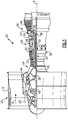
- FIG. 1 schematically illustrates a gas turbine engine 20.
- the gas turbine engine 20 is disclosed herein as a two-spool turbofan that generally incorporates a fan section 22, a compressor section 24, a combustor section 26 and a turbine section 28.
- Alternative engines might include an augmentor section (not shown) among other systems or features.
- the fan section 22 drives air along a bypass flow path B in a bypass duct defined within a nacelle 15, while the compressor section 24 drives air along a core flow path C for compression and communication into the combustor section 26 then expansion through the turbine section 28.
- the exemplary engine 20 generally includes a low speed spool 30 and a high speed spool 32 mounted for rotation about an engine central longitudinal axis A relative to an engine static structure 36 via several bearing systems 38. It should be understood that various bearing systems 38 at various locations may alternatively or additionally be provided, and the location of bearing systems 38 may be varied as appropriate to the application.
- the low speed spool 30 generally includes an inner shaft 40 that interconnects a fan 42, a first (or low) pressure compressor 44 and a second (or low) pressure turbine 46.
- the inner shaft 40 is connected to the fan 42 through a speed change mechanism, which in exemplary gas turbine engine 20 is illustrated as a geared architecture 48 to drive the fan 42 at a lower speed than the low speed spool 30.
- the high speed spool 32 includes an outer shaft 50 that interconnects a second (or high) pressure compressor 52 and a first (or high) pressure turbine 54.
- a combustor 56 is arranged in exemplary gas turbine 20 between the high pressure compressor 52 and the high pressure turbine 54.
- a mid-turbine frame 57 of the engine static structure 36 is arranged generally between the high pressure turbine 54 and the low pressure turbine 46.
- the mid-turbine frame 57 further supports bearing systems 38 in the turbine section 28.
- the inner shaft 40 and the outer shaft 50 are concentric and rotate via bearing systems 38 about the engine central longitudinal axis A which is collinear with their longitudinal axes.
- the core airflow is compressed by the low pressure compressor 44 then the high pressure compressor 52, mixed and burned with fuel in the combustor 56, then expanded over the high pressure turbine 54 and low pressure turbine 46.
- the mid-turbine frame 57 includes airfoils 59 which are in the core airflow path C.
- the turbines 46, 54 rotationally drive the respective low speed spool 30 and high speed spool 32 in response to the expansion.
- gear system 48 may be located aft of combustor section 26 or even aft of turbine section 28, and fan section 22 may be positioned forward or aft of the location of gear system 48.
- the geared architecture 48 may be an epicycle gear train, such as a planetary gear system or other gear system, with a gear reduction ratio of greater than about 2.3:1. It should be understood, however, that the above parameters are only exemplary of one embodiment of a geared architecture engine and that the present invention is applicable to other gas turbine engines including direct drive turbofans.
- the airfoil 61 can alternatively be integrally formed with the rotor 60, which is sometimes referred to as an integrally bladed rotor (IBR).
- a blade outer air seal (BOAS) 69 is spaced radially outward from the tip 64 of the airfoil section 65.
- a vane 70 is positioned along the engine axis A and adjacent to the airfoil 61.
- the vane 70 includes an airfoil section 71 extending between an inner platform 72 and an outer platform 73 to define a portion of the core flow path C.
- the turbine section 28 includes multiple airfoils 61, vanes 70, and BOAS 69 arranged circumferentially about the engine axis A.
- the outer platform 73 of vane 70 and BOAS 69 can define one or more outer cooling cavities 74.
- the platform 62 of airfoil 61 and the inner platform 72 of vane 70 can define one or more inner cooling cavities 75.
- the cooling cavities 74, 75 are configured to receive cooling flow from one or more cooling sources 76 to cool portions of the airfoil 61, BOAS 69 and/or vane 70.
- Cooling sources 76 can include bleed air from an upstream stage of the compressor section 24 (shown in Figure 1 ), bypass air, or a secondary cooling system aboard the aircraft, for example.
- Each of the cooling cavities 74, 75 can extend circumferentially in a thickness direction T between adjacent airfoils 61, BOAS 69 and/or vanes 70, for example.
- the airfoils 61, vanes 70 and/or BOAS 69 can include one or more seal members 82 to bound the core flow path C, or otherwise reduce fluid communication between the cooling cavities 74, 75 and the core flow path C.
- the seal members 82 are arranged adjacent to mate faces 81 of the airfoils 61, vanes 70 and/or BOAS 69.
- Airfoil 161 ( Figure 3 ) includes a cold side surface 180 adjacent to mate face 181.
- the cold side surface 180 is located on an undersurface of the platform 162.
- a seal member 182 abuts the cold side surface 180 of the platform 162 to bound the cooling cavity 75 ( Figure 2 ).
- the cold side surface 180 is located at a slot 183 extending inwardly from the mate face 181.
- the seal member 182 is received in the slot 183, which is dimensioned to limit relative movement of the seal member 182.
- the airfoil 161 may be provided with a support member 190 extending from root section 167 to define a radially inward portion of the slot 183.
- the seal member 182 defines an axis B ( Figure 4A ) between the leading and trailing edge regions 187, 188.
- the axis B extends in a direction substantially parallel to chordwise direction X.
- the axis B is substantially perpendicular to the thickness direct T or the direction of rotation of the airfoil 161.
- the axis B is substantially parallel to the engine axis A ( Figure 1 ).
- the seal member 182 defines one or more grooves 184 in a thickness of the seal member 182.
- the grooves 184 can be stamped, machined, or cast into the seal member 182, for example.
- the seal member 182 and grooves 184 are formed by additive manufacturing.
- the grooves 184 are arranged to abut the cold side surface 180 to define a plurality of cooling passages 191.
- Each of the grooves 184 extends between a first end 185 and a second end 186 ( Figures 4A-4B ).
- the grooves 184 are situated relative to the cold side surface 180 and coolant source 76 ( Figure 2 ) to establish a flow through the corresponding cooling passages 191.
- Each first end 185 is arranged relative to the cooling flow to define an inlet of the corresponding passage 191.
- the second end 186 corresponds to an outlet of the corresponding passage 191, the inlet corresponding to the first end 185 being upstream of the second end 186, for example.
- the second end 186 is arranged relative to the cooling flow to define an addition or second inlet of the corresponding passage 191.
- the first ends 185A-185C and corresponding inlets of the passages 191 are defined along at least one of the sidewalls 189 corresponding to the pressure and/or suction sides of the airfoil section 165.
- the first ends 185 of one or more of the grooves 184 taper inwardly to define a flared inlet, as illustrated by first ends 185A-185C.
- the first ends 185A-185C define a width W 1 that is greater than a minimum width W 2 of the groove 184 ( Figure 4C ). In some examples, a ratio of the width W 1 to the width W 2 is greater than or equal to about 1.2:1. In other examples, the ratio is between about 1.2:1 and about 3:1.
- the second ends 186A-186C are situated relative to the sidewalls 189 such that the outlets of the corresponding cooling passages 191 eject coolant into the leakage gap G.
- the second ends 186A-186C are separated from the first ends 185A-185C in the chordwise direction X such that corresponding outlets of the passages 191 are established adjacent to the mate face 181.
- the second ends 186A-186C are spaced from the sidewalls 189 such that a single outlet is defined adjacent to mate face 181 for each of the corresponding passages 191.
- One or more of the second ends 186 can be arranged relative to the first ends 185 such that the second ends 186 define a second inlet to the corresponding passages 191, as depicted by groove 184D, for example.
- the arrangement of multiple inlets for a single passage 191 can be utilized to reduce plugging caused by debris or other particulates carried in the secondary leakage air communicated from the coolant source 76 ( Figure 2 ), for example.
- a projection of each of the grooves 184A-184D onto a plane defined by axis T, X is substantially linear, and a projection of each of the grooves 184A-184C onto a plane defined by axis R, X is curved.
- at least some of the grooves 284A-284B can have a curved profile relative to the R, X plane.
- One or more of the grooves 284C (one depicted) can include a first end 285 defining a flared inlet along a leading edge region 287 of seal member 282.
- the grooves can have a complex geometry, such as a circuitous or serpentine profile shown by grooves 384A-384B.
- the first ends 385A-385B are located on two or more sidewalls 389 of seal member 382 and second ends 386A-386B are located on opposite sides of leakage gap G.
- One or more of the second ends and corresponding outlets of the cooling passages can be located along the trailing edge region, illustrated by second end 386C of groove 384C.
- Mate faces 481A, 481B of airfoils 461A, 461B are arranged adjacent to each other to define leakage gap G adjacent to core flow path C.
- Seal member 482 is arranged adjacent to cold side surfaces 480A, 480B to reduce flow between, or otherwise separate, cavity 475 and the core flow path C.
- the cavity 475 is provided with secondary cooling air, for example.
- Figure 7 illustrates a cooling arrangement 578 for adjacent components according to another example.
- the adjacent components are BOAS 569A, 569B.
- Mate faces 581A, 581B of BOAS 569A, 569B are situated adjacent to each other define leakage gap G.
- Seal member 582 is arranged within slots 583A, 583B of BOAS 569A, 569B to restrict flow through the gap G.
- the seal member 582 includes one or more grooves 584 to define corresponding cooling passages 591 (one shown), according to any of the arrangements discussed herein.
Landscapes
- Engineering & Computer Science (AREA)
- General Engineering & Computer Science (AREA)
- Mechanical Engineering (AREA)
- Turbine Rotor Nozzle Sealing (AREA)
Abstract
Description
- This disclosure relates to cooling for a component of a gas turbine engine, and more particularly to a seal having one or more grooves for cooling augmentation.
- Gas turbine engines can include a fan for propulsion air and to cool components. The fan also delivers air into a core engine where it is compressed. The compressed air is then delivered into a combustion section, where it is mixed with fuel and ignited. The combustion gas expands downstream over and drives turbine blades. Static vanes are positioned adjacent to the turbine blades to control the flow of the products of combustion. The blades and vanes are subject to extreme heat, and thus cooling schemes are utilized for each.
- Adjacent blades or vanes are distributed to define leakage gaps at adjacent mate faces. Cooling airflow is communicated through the leakage gaps to cool surfaces adjacent to the mate faces.
- A seal arrangement for a gas turbine engine according to an example of the present disclosure includes a component including a body having a cold side surface adjacent to a mate face, and a seal member including a leading edge region and a trailing edge region spaced by sidewalls. The seal member defines one or more grooves. The one or more grooves abut the cold side surface to define one or more cooling passages, with at least one of the one or more cooling passages having a flared inlet defined by a corresponding one of the one or more grooves.
- In an embodiment of the foregoing embodiment, each of the one or more cooling passages has a flared inlet.
- In a further embodiment of any of the foregoing embodiments, the flared inlet is located along one of the sidewalls or the leading edge region.
- In a further embodiment of any of the foregoing embodiments, the seal member defines an axis extending between the leading edge and the trailing edge, and at least some of the grooves are transverse to the axis.
- In a further embodiment of any of the foregoing embodiments, at least some of the one or more grooves includes a second end adjacent to the mate face. The second end is opposite to a first end defining the corresponding flared inlet.
- In a further embodiment of any of the foregoing embodiments, the second end of at least some of the grooves are spaced from each of the sidewalls.
- In a further embodiment of any of the foregoing embodiments, the cold side surface is located at a slot extending inwardly from the mate face, and the slot is configured to receive the seal member.
- In a further embodiment of any of the foregoing embodiments, at least some of the one or more grooves have a curved profile.
- In a further embodiment of any of the foregoing embodiments, the component is an airfoil. The airfoil includes an airfoil section extending from a platform, and the first cold side surface is located at the platform.
- A gas turbine engine according to an example of the present disclosure includes a first component and a second component arranged about an axis. The first component includes a first cold side surface adjacent to a first mate face. The second component includes a second cold side surface adjacent to a second mate face. The first and second mate faces are arranged to define a leakage gap. A seal member defines a plurality of grooves adjacent to the leakage gap. The plurality of grooves abut the first and second cold side surfaces to define a plurality of cooling passages in communication with the leakage gap. One or more of the plurality of cooling passages has a flared inlet and an outlet adjacent to the leakage gap.
- In an embodiment of the foregoing embodiment, the first cold side surface is located at a slot extending inwardly from the first mate face, and the slot is configured to receive the seal member.
- In a further embodiment of any of the foregoing embodiments, the seal member includes a leading edge region and a trailing edge region spaced by sidewalls, and the outlet of at least some of the plurality of cooling passages are spaced apart from the sidewalls.
- In a further embodiment of any of the foregoing embodiments, the seal member is moveable between a first position and a second position relative to the first component, and the outlet of at least some of the plurality of cooling passages are spaced from the sidewalls when the seal member is in the first and second positions.
- In a further embodiment of any of the foregoing embodiments, the flared inlet of one or more of the plurality of passages are spaced from the sidewalls.
- In a further embodiment of any of the foregoing embodiments, one or more of the plurality of grooves are transverse to the leakage gap.
- In a further embodiment of any of the foregoing embodiments, each of the first and second components is one of an airfoil and a blade outer air seal (BOAS).
- In a further embodiment of any of the foregoing embodiments, the first components is an airfoil. The airfoil includes an airfoil section extending from a platform. The platform includes an upper surface bounding a core flow path and an undersurface bounding a cooling cavity, and the first cold side surface is located at the undersurface of the platform.
- A method of sealing between adjacent components of a gas turbine engine according to an example of the present disclosure includes providing a feather seal defining one or more grooves, and positioning the feather seal across a leakage gap defined between mate faces of adjacent components such that the one or more grooves define cooling passages. One or more of the cooling passages of the cooling passages has a flared inlet, and the one or more grooves are transverse to a projection of at least one of the mate faces.
- In an embodiment of the foregoing embodiment, the method includes communicating coolant through the cooling passages in response to relative movement of the feather seal and at least one of the mate faces wherein an end of one of the grooves opposite the corresponding flared inlet is spaced between sidewalls of the feather seal.
- In a further embodiment of any of the foregoing embodiments, the flared inlet is located along a leading edge region of the feather seal.
- Although the different examples have the specific components shown in the illustrations, embodiments of this disclosure are not limited to those particular combinations. It is possible to use some of the components or features from one of the examples in combination with features or components from another one of the examples.
- The various features and advantages of this invention will become apparent to those skilled in the art from the following detailed description of an embodiment. The drawings that accompany the detailed description can be briefly described as follows.
-
-
Figure 1 schematically shows a gas turbine engine. -
Figure 2 schematically shows an airfoil arrangement for a turbine section. -
Figure 3 illustrates a side view of a first embodiment of a cooling arrangement for an airfoil. -
Figure 4A illustrates a plan view of a seal member that can be utilized in the arrangement ofFigure 3 . -
Figure 4B illustrates a side view of the seal member ofFigure 4A . -
Figure 4C illustrates selected portions of the seal member ofFigure 4B . -
Figure 5A illustrates a plan view of a second embodiment of a seal member. -
Figure 5B illustrates a plan view of a third embodiment of a seal member. -
Figure 6 illustrates a cross-sectional view of a seal member and adjacent airfoils according to an embodiment. -
Figure 7 illustrates a cross-sectional view of a seal member and adjacent components according to another embodiment. -
Figure 1 schematically illustrates agas turbine engine 20. Thegas turbine engine 20 is disclosed herein as a two-spool turbofan that generally incorporates afan section 22, acompressor section 24, a combustor section 26 and aturbine section 28. Alternative engines might include an augmentor section (not shown) among other systems or features. Thefan section 22 drives air along a bypass flow path B in a bypass duct defined within anacelle 15, while thecompressor section 24 drives air along a core flow path C for compression and communication into the combustor section 26 then expansion through theturbine section 28. Although depicted as a two-spool turbofan gas turbine engine in the disclosed non-limiting embodiment, it should be understood that the concepts described herein are not limited to use with two-spool turbofans as the teachings may be applied to other types of turbine engines including three-spool architectures. - The
exemplary engine 20 generally includes alow speed spool 30 and ahigh speed spool 32 mounted for rotation about an engine central longitudinal axis A relative to an enginestatic structure 36 viaseveral bearing systems 38. It should be understood that various bearingsystems 38 at various locations may alternatively or additionally be provided, and the location of bearingsystems 38 may be varied as appropriate to the application. - The
low speed spool 30 generally includes aninner shaft 40 that interconnects afan 42, a first (or low)pressure compressor 44 and a second (or low)pressure turbine 46. Theinner shaft 40 is connected to thefan 42 through a speed change mechanism, which in exemplarygas turbine engine 20 is illustrated as a gearedarchitecture 48 to drive thefan 42 at a lower speed than thelow speed spool 30. Thehigh speed spool 32 includes anouter shaft 50 that interconnects a second (or high)pressure compressor 52 and a first (or high)pressure turbine 54. Acombustor 56 is arranged inexemplary gas turbine 20 between thehigh pressure compressor 52 and thehigh pressure turbine 54. Amid-turbine frame 57 of the enginestatic structure 36 is arranged generally between thehigh pressure turbine 54 and thelow pressure turbine 46. Themid-turbine frame 57 furthersupports bearing systems 38 in theturbine section 28. Theinner shaft 40 and theouter shaft 50 are concentric and rotate via bearingsystems 38 about the engine central longitudinal axis A which is collinear with their longitudinal axes. - The core airflow is compressed by the
low pressure compressor 44 then thehigh pressure compressor 52, mixed and burned with fuel in thecombustor 56, then expanded over thehigh pressure turbine 54 andlow pressure turbine 46. Themid-turbine frame 57 includesairfoils 59 which are in the core airflow path C. Theturbines low speed spool 30 andhigh speed spool 32 in response to the expansion. It will be appreciated that each of the positions of thefan section 22,compressor section 24, combustor section 26,turbine section 28, and fandrive gear system 48 may be varied. For example,gear system 48 may be located aft of combustor section 26 or even aft ofturbine section 28, andfan section 22 may be positioned forward or aft of the location ofgear system 48. - The
engine 20 in one example is a high-bypass geared aircraft engine. In a further example, theengine 20 bypass ratio is greater than about six, with an example embodiment being greater than about ten, the gearedarchitecture 48 is an epicyclic gear train, such as a planetary gear system or other gear system, with a gear reduction ratio of greater than about 2.3 and thelow pressure turbine 46 has a pressure ratio that is greater than about five. In one disclosed embodiment, theengine 20 bypass ratio is greater than about ten, the fan diameter is significantly larger than that of thelow pressure compressor 44, and thelow pressure turbine 46 has a pressure ratio that is greater than about five.Low pressure turbine 46 pressure ratio is pressure measured prior to inlet oflow pressure turbine 46 as related to the pressure at the outlet of thelow pressure turbine 46 prior to an exhaust nozzle. The gearedarchitecture 48 may be an epicycle gear train, such as a planetary gear system or other gear system, with a gear reduction ratio of greater than about 2.3:1. It should be understood, however, that the above parameters are only exemplary of one embodiment of a geared architecture engine and that the present invention is applicable to other gas turbine engines including direct drive turbofans. - A significant amount of thrust is provided by the bypass flow B due to the high bypass ratio. The
fan section 22 of theengine 20 is designed for a particular flight condition -- typically cruise at about 0.8 Mach and about 35,000 feet (10,668 m). The flight condition of 0.8 Mach and 35,000 ft (10,668 m), with the engine at its best fuel consumption - also known as "bucket cruise Thrust Specific Fuel Consumption ('TSFC')" - is the industry standard parameter of lbm of fuel being burned divided by lbf of thrust the engine produces at that minimum point. "Low fan pressure ratio" is the pressure ratio across the fan blade alone, without a Fan Exit Guide Vane ("FEGV") system. The low fan pressure ratio as disclosed herein according to one non-limiting embodiment is less than about 1.45. "Low corrected fan tip speed" is the actual fan tip speed in ft/sec divided by an industry standard temperature correction of [(Tram °R) / (518.7 °R)]0.5 (where °R = K x 9/5). The "Low corrected fan tip speed" as disclosed herein according to one non-limiting embodiment is less than about 1150 ft / second (350.5 m/s). -
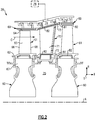
Figure 2 shows selected portions of theturbine section 28 including arotor 60 carrying one ormore airfoils 61 for rotation about the central axis A. In this disclosure, like reference numerals designate like elements where appropriate and reference numerals with the addition of one-hundred or multiples thereof designate modified elements that are understood to incorporate the same features and benefits of the corresponding original elements. Eachairfoil 61 includes aplatform 62 and anairfoil section 65 extending in a radial direction R from theplatform 62 to atip 64. Theairfoil section 65 generally extends in a chordwise direction X between aleading edge 66 and a trailingedge 68. Aroot section 67 of theairfoil 61 is mounted to therotor 60, for example. It should be understood that theairfoil 61 can alternatively be integrally formed with therotor 60, which is sometimes referred to as an integrally bladed rotor (IBR). A blade outer air seal (BOAS) 69 is spaced radially outward from thetip 64 of theairfoil section 65. Avane 70 is positioned along the engine axis A and adjacent to theairfoil 61. Thevane 70 includes anairfoil section 71 extending between aninner platform 72 and anouter platform 73 to define a portion of the core flow path C. Theturbine section 28 includesmultiple airfoils 61,vanes 70, andBOAS 69 arranged circumferentially about the engine axis A. - The
outer platform 73 ofvane 70 andBOAS 69 can define one or more outer coolingcavities 74. Theplatform 62 ofairfoil 61 and theinner platform 72 ofvane 70 can define one or moreinner cooling cavities 75. The cooling cavities 74, 75 are configured to receive cooling flow from one ormore cooling sources 76 to cool portions of theairfoil 61,BOAS 69 and/orvane 70.Cooling sources 76 can include bleed air from an upstream stage of the compressor section 24 (shown inFigure 1 ), bypass air, or a secondary cooling system aboard the aircraft, for example. Each of thecooling cavities adjacent airfoils 61,BOAS 69 and/orvanes 70, for example. - The
airfoils 61,vanes 70 and/orBOAS 69 can include one ormore seal members 82 to bound the core flow path C, or otherwise reduce fluid communication between the coolingcavities seal members 82 are arranged adjacent to mate faces 81 of theairfoils 61,vanes 70 and/orBOAS 69. -
Figures 3 and 4A to 4C illustrate an exemplary sealing arrangement 178 for adjacent components. Although the exemplary sealing arrangements discussed herein primarily refer to a turbine blade, the teachings herein can also be utilized for another portion of theengine 20, such asBOAS 69,vane 70, an upstream stage of thecompressor section 24, or combustor panels located in the combustor section 26 and defining portions of a combustion chamber, exhaust nozzles, or augmentors, for example. The exemplary cooling arrangements discussed herein can also be utilized adjacent to thecooling cavities - Airfoil 161 (
Figure 3 ) includes acold side surface 180 adjacent to mateface 181. Thecold side surface 180 is located on an undersurface of theplatform 162. Aseal member 182 abuts thecold side surface 180 of theplatform 162 to bound the cooling cavity 75 (Figure 2 ). In the illustrated example, thecold side surface 180 is located at aslot 183 extending inwardly from themate face 181. Theseal member 182 is received in theslot 183, which is dimensioned to limit relative movement of theseal member 182. Theairfoil 161 may be provided with asupport member 190 extending fromroot section 167 to define a radially inward portion of theslot 183. - The
seal member 182 can be fabricated from sheet metal made of nickel or cobalt, for example. Other materials for theseal member 182 can be utilized, including various high temperature Ni, Cobalt, or Inco alloys, or composite materials, for example. In the illustrated example, theseal member 182 is a feature seal configured to at least partially seal cooling cavity 75 (Figure 2 ) from the core flow path C, and is also configured to dampen vibrations ofairfoil 161 that may occur during operation of theengine 20. The localized cooling techniques described herein reduce a likelihood of creep of theseal member 182 caused by excessive heat exposure, thereby reducing a likelihood of degradation in the dampening characteristics of theseal member 182. - The
seal member 182 includes aleading edge region 187, a trailingedge region 188, and one or more sidewalls 189. The leading edge region, 187, trailingedge region 188, and/orsidewalls 189 can be substantially planar, curved, or have another suitable geometry corresponding to adjacent surfaces of theairfoil 161. - The
seal member 182 defines an axis B (Figure 4A ) between the leading and trailingedge regions airfoil 161. In some examples, the axis B is substantially parallel to the engine axis A (Figure 1 ). - The
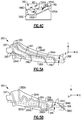
seal member 182 defines one ormore grooves 184 in a thickness of theseal member 182. Thegrooves 184 can be stamped, machined, or cast into theseal member 182, for example. In another example, theseal member 182 andgrooves 184 are formed by additive manufacturing. As illustrated inFigure 3 , thegrooves 184 are arranged to abut thecold side surface 180 to define a plurality of coolingpassages 191. Each of thegrooves 184 extends between afirst end 185 and a second end 186 (Figures 4A-4B ). Thegrooves 184 are situated relative to thecold side surface 180 and coolant source 76 (Figure 2 ) to establish a flow through thecorresponding cooling passages 191. Eachfirst end 185 is arranged relative to the cooling flow to define an inlet of thecorresponding passage 191. In some examples, thesecond end 186 corresponds to an outlet of thecorresponding passage 191, the inlet corresponding to thefirst end 185 being upstream of thesecond end 186, for example. In other examples, thesecond end 186 is arranged relative to the cooling flow to define an addition or second inlet of thecorresponding passage 191. - The
grooves 184 are situated relative tomate face 181 such that thecooling passages 191 eject coolant into a leakage gap G (shown schematically inFigure 4A and inFigure 6 ). One or more of thegrooves 184 can be oriented transverse to the axis B and/or a projection of at least one of the mate faces, such asgrooves 184A-184C. As seen inFigure 4A , thegrooves 184A-184C can be aimed in an aft direction relative to axis B, or otherwise angled relative to the chordwise direction X, to target a localized area of leakage gap G to achieve a lower dump pressure. This arrangement can be utilized to ensure adequate backflow margin in thepassages 191 and the leakage gap G, thereby reducing a likelihood of ingestion of hot combustion gases in the core flow path C through the leakage gap G. The transverse orientation also increases a length of thegrooves 184A-184C, thereby increasing convective cooling provided to adjacent portions of thecold side surface 180 andseal member 182. The localized cooling techniques described herein can utilize secondary leakage air from the coolant source 76 (Figure 2 ), which has a lower performance loss than dedicated cooling air that may be communicated to theairfoil 162, for example. Accordingly, the localized cooling techniques described herein can be utilized to reduce the overall cooling air demand and improve overall engine efficiency. Theseal member 182 can define one ormore grooves 184 substantially perpendicular to the axis B, such asgroove 184D. - The first ends 185A-185C and corresponding inlets of the
passages 191 are defined along at least one of thesidewalls 189 corresponding to the pressure and/or suction sides of theairfoil section 165. The first ends 185 of one or more of thegrooves 184 taper inwardly to define a flared inlet, as illustrated byfirst ends 185A-185C. The first ends 185A-185C define a width W1 that is greater than a minimum width W2 of the groove 184 (Figure 4C ). In some examples, a ratio of the width W1 to the width W2 is greater than or equal to about 1.2:1. In other examples, the ratio is between about 1.2:1 and about 3:1. For the purposes of this disclosure, the term "about" means ±3 percent of the given value, unless otherwise indicated. Additionally, edges of the first ends 185A-185C can be defined with a suitable contouring, such as round or bevel, to reduce flow instability adjacent to the flared inlets, for example. - The second ends 186A-186C are situated relative to the
sidewalls 189 such that the outlets of thecorresponding cooling passages 191 eject coolant into the leakage gap G. The second ends 186A-186C are separated from the first ends 185A-185C in the chordwise direction X such that corresponding outlets of thepassages 191 are established adjacent to themate face 181. The second ends 186A-186C are spaced from thesidewalls 189 such that a single outlet is defined adjacent to mateface 181 for each of thecorresponding passages 191. One or more of the second ends 186 can be arranged relative to the first ends 185 such that the second ends 186 define a second inlet to thecorresponding passages 191, as depicted bygroove 184D, for example. The arrangement of multiple inlets for asingle passage 191 can be utilized to reduce plugging caused by debris or other particulates carried in the secondary leakage air communicated from the coolant source 76 (Figure 2 ), for example. - In the illustrated example of
Figures 4A to 4C , a projection of each of thegrooves 184A-184D onto a plane defined by axis T, X is substantially linear, and a projection of each of thegrooves 184A-184C onto a plane defined by axis R, X is curved. In the illustrated example ofFigure 5A , at least some of thegrooves 284A-284B can have a curved profile relative to the R, X plane. One or more of thegrooves 284C (one depicted) can include afirst end 285 defining a flared inlet along aleading edge region 287 ofseal member 282. At least some of thegrooves 284 can have two or more first ends 285 and/or two or more second ends 286, as illustrated bygroove 284B, such that the corresponding cooling passage branches into two or more passage sections to provide cooling augmentation to localized portions of the airfoil 161 (Figure 3 ) and/orseal member 282. - In the illustrated example of
Figure 5B , at least some of the grooves can have a complex geometry, such as a circuitous or serpentine profile shown bygrooves 384A-384B. The first ends 385A-385B are located on two or more sidewalls 389 ofseal member 382 and second ends 386A-386B are located on opposite sides of leakage gap G. One or more of the second ends and corresponding outlets of the cooling passages can be located along the trailing edge region, illustrated bysecond end 386C ofgroove 384C. - Referring to
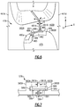
Figure 6 , a method of sealing utilizing the sealing arrangements discussed herein is described as follows. Mate faces 481A, 481B ofairfoils C. Seal member 482 is arranged adjacent to cold side surfaces 480A, 480B to reduce flow between, or otherwise separate,cavity 475 and the core flow path C. Thecavity 475 is provided with secondary cooling air, for example. - One or more grooves 484 (one shown for illustrative purposes) are arranged adjacent to the cold side surfaces 480A, 480B to establish a flow path for fluid F through
corresponding cooling passage 491.First end 485 ofgroove 484 tapers inwardly fromsidewall 489 to define a flared inlet 494 of thecooling passage 491. Fluid F is communicated to the inlet and through thepassage 491 to provide convective cooling to adjacent portions of cold side surface 480A andseal member 482. Thereafter, the relative warm fluid F is ejected fromoutlet 496 of thepassage 491 into the leakage gap G. It should be appreciated that the tapered geometry of the flared inlet reduces a relative pressure with respect to the fluid F such that a velocity of the fluid F may be insufficient to carry debris or particulates into thecooling passage 491. This arrangement reduces a likelihood of pressure loss at the inlet caused by blockage by such debris or particulates, thereby improving the cooling characteristics and durability of theseal arrangement 478. - During operation of the engine 20 (
Figure 1 ), theseal member 482 may move relative to the mate faces 481A, 481B between a first position and a second position, such as in the circumferential or thickness direction T. Thesecond end 486 can be situated between a projection of themate face 481B and theadjacent sidewall 489 such that the outlet is spaced from each of thesidewalls 489 when in the first and second positions to reduce a likelihood of blockage of the outlets. Thesecond end 486 can also be situated to account for relative movement in the axial or chordwise direction X, for example. -
Figure 7 illustrates acooling arrangement 578 for adjacent components according to another example. In the illustrated example, the adjacent components areBOAS BOAS G. Seal member 582 is arranged withinslots BOAS seal member 582 includes one ormore grooves 584 to define corresponding cooling passages 591 (one shown), according to any of the arrangements discussed herein. - Although particular step sequences are shown, described, and claimed, it should be understood that steps may be performed in any order, separated or combined unless otherwise indicated and will still benefit from the present disclosure.
- It should be understood that relative positional terms such as "forward," "aft," "upper," "lower," "above," "below," and the like are with reference to the normal operational attitude of the vehicle and should not be considered otherwise limiting.
- The foregoing description is exemplary rather than defined by the limitations within. Various non-limiting embodiments are disclosed herein, however, one of ordinary skill in the art would recognize that various modifications and variations in light of the above teachings will fall within the scope of the appended claims. It is therefore to be understood that within the scope of the appended claims, the disclosure may be practiced other than as specifically described. For that reason the appended claims should be studied to determine true scope and content.
Claims (15)
- A seal arrangement (178;478;578) for a gas turbine engine (20), comprising:a component (61;69;70;161;461A,461B;569A,569B) including a body having a cold side surface (180;480A,480B) adjacent to a mate face (81;181;481A,481B;581A,581B); anda seal member (82;182;282;382;482) including a leading edge region (187;287;387) and a trailing edge region (188;288;388) spaced by sidewalls (189;289;389;489;589), the seal member (82...482) defining one or more grooves (184;284;384;484;584), the one or more grooves (184...584) abutting the cold side surface (180;480A,480B) to define one or more cooling passages (191;491;591), with at least one of the one or more cooling passages (191;491;591) having a flared inlet (494) defined by a corresponding one of the one or more grooves (184...584).
- The seal arrangement as recited in claim 1, wherein:each of the one or more cooling passages (191;491;591) has a flared inlet (494); and/orthe flared inlet (494) is located along one of the sidewalls (189...589) or the leading edge region (187;287;387).
- The seal arrangement as recited in claim 1 or 2, wherein the seal member (82...482) defines an axis (B) extending between the leading edge region (187;287;387) and the trailing edge region (188;288;388), and at least some of the grooves (184...584) are transverse to the axis (B).
- The seal arrangement as recited in claim 1, 2 or 3, wherein:at least some of the one or more grooves (184...584) includes a second end (186,186A-C;286;386A-C;486) adjacent to the mate face (181...581B), the second end (186...486) opposite to a first end (185,185A-C;285;385A-C;485) defining the corresponding flared inlet (494), and wherein, optionally, the second end (186...486) of at least some of the grooves (184...584) are spaced from each of the sidewalls (189...589); and/orat least some of the one or more grooves (184...584) have a curved profile.
- The seal arrangement as recited in any preceding claim, wherein the cold side surface (180;480A,480B) is located at a slot (183;583A,583B) extending inwardly from the mate face (81...581B), and the slot (183;583A,583B) is configured to receive the seal member (82...482).
- The seal arrangement as recited in any preceding claim, wherein the component is an airfoil (61;161;461A,461B), the airfoil (61...461B) including an airfoil section (65;165) extending from a platform (62;162), and the cold side surface (180;480A,480B) is located at the platform (62;162).
- A gas turbine engine (20), comprising the seal arrangement of any preceding claim, wherein the component is a first component (461A;569A) including a first cold side surface (480A) adjacent to a first mate face (481A;581B), the gas turbine engine (20) further comprising:a second component (461B;569B) arranged about an axis, the second component (461B;569B) including a second cold side surface (480B) adjacent to a second mate face (481B;581B), the first and second mate faces (481A,481B;581A,581B) arranged to define a leakage gap (G); andthe seal member (482;582) defining a plurality of grooves (584) adjacent to the leakage gap (481A;581A), the plurality of grooves (584) abutting the first and second cold side surfaces (480A,480B) to define a plurality of cooling passages (491;591) in communication with the leakage gap (G), one or more of the plurality of cooling passages (491;591) having a flared inlet (494) and an outlet (496) adjacent to the leakage gap (G).
- The gas turbine engine as recited in claim 7, wherein the first cold side surface (480A) is located at a slot (583A,583B) extending inwardly from the first mate face (481A;581A), and the slot (583A,583B) is configured to receive the seal member (482;582).
- The gas turbine engine as recited in claim 7 or 8, wherein the seal member (482;582) includes a leading edge region and a trailing edge region spaced by sidewalls (489;589), and the outlet (496) of at least some of the plurality of cooling passages (491;591) are spaced apart from the sidewalls (489;589), wherein, optionally, the seal member (482;582) is moveable between a first position and a second position relative to the first component (461A;569A), and the outlet (496) of at least some of the plurality of cooling passages (491;591) are spaced from the sidewalls (489;589) when the seal member (482;582) is in the first and second positions.
- The gas turbine engine as recited in claim 7, 8 or 9, wherein one or more of the plurality of grooves (584) are transverse to the leakage gap (G).
- The gas turbine engine as recited in any of claims 7 to 10, wherein each of the first and second components (461A,461B;569A,569B) is one of an airfoil (461A,461B) and a blade outer air seal (BOAS) (569A,569B).
- The gas turbine engine as recited in claim 11, wherein the first component is an airfoil (461A), the airfoil (461A) including an airfoil section extending from a platform, the platform including an upper surface bounding a core flow path (C) and an undersurface bounding a cooling cavity (475), and the first cold side surface (480A) is located at the undersurface of the platform.
- A method of sealing between adjacent components (461A,461B;569A,569B) of a gas turbine engine (20), comprising:providing a feather seal (482;582) defining one or more grooves (584); andpositioning the feather seal (482;582) across a leakage gap (G) defined between mate faces (481A,481B;581A,581B) of adjacent components (461A,461B;569A,569B) such that the one or more grooves (584) define cooling passages (491;591), one or more of the cooling passages (491;591) having a flared inlet (494), and the one or more grooves (584) being transverse to a projection of at least one of the mate faces (481A,481B;581A,581B).
- The method as recited in claim 13, comprising:communicating coolant (F) through the cooling passages (491;591) in response to relative movement of the feather seal (482;582) and at least one of the mate faces (481A,481B;581A,581B); andwherein an end of one of the grooves (584) opposite the corresponding flared inlet (494) is spaced between sidewalls (489;589) of the feather seal (482;582).
- The method as recited in claim 13 or 14, wherein the flared inlet (494) is located along a leading edge region of the feather seal (482;582).
Applications Claiming Priority (1)
| Application Number | Priority Date | Filing Date | Title |
|---|---|---|---|
| US14/945,835 US9822658B2 (en) | 2015-11-19 | 2015-11-19 | Grooved seal arrangement for turbine engine |
Publications (2)
| Publication Number | Publication Date |
|---|---|
| EP3170989A1 true EP3170989A1 (en) | 2017-05-24 |
| EP3170989B1 EP3170989B1 (en) | 2020-04-15 |
Family
ID=57348601
Family Applications (1)
| Application Number | Title | Priority Date | Filing Date |
|---|---|---|---|
| EP16199689.7A Active EP3170989B1 (en) | 2015-11-19 | 2016-11-18 | Grooved seal arrangement for turbine engine |
Country Status (2)
| Country | Link |
|---|---|
| US (2) | US9822658B2 (en) |
| EP (1) | EP3170989B1 (en) |
Families Citing this family (3)
| Publication number | Priority date | Publication date | Assignee | Title |
|---|---|---|---|---|
| US10190502B2 (en) | 2016-06-23 | 2019-01-29 | Delavan Inc. | Brazing components and techniques |
| US10927692B2 (en) * | 2018-08-06 | 2021-02-23 | General Electric Company | Turbomachinery sealing apparatus and method |
| US11566528B2 (en) * | 2019-12-20 | 2023-01-31 | General Electric Company | Rotor blade sealing structures |
Citations (7)
| Publication number | Priority date | Publication date | Assignee | Title |
|---|---|---|---|---|
| US5513955A (en) * | 1994-12-14 | 1996-05-07 | United Technologies Corporation | Turbine engine rotor blade platform seal |
| EP1452694A2 (en) * | 2003-02-26 | 2004-09-01 | ROLLS-ROYCE plc | Damper and seal for turbine |
| WO2007063128A1 (en) * | 2005-12-02 | 2007-06-07 | Siemens Aktiengesellschaft | Blade platform cooling in turbomachines |
| EP2055898A2 (en) * | 2007-11-02 | 2009-05-06 | United Technologies Corporation | Turbine airfoil with platform cooling |
| US8382424B1 (en) * | 2010-05-18 | 2013-02-26 | Florida Turbine Technologies, Inc. | Turbine vane mate face seal pin with impingement cooling |
| WO2015026416A2 (en) * | 2013-06-03 | 2015-02-26 | United Technologies Corporation | Vibration dampers for turbine blades |
| WO2015084449A2 (en) * | 2013-09-17 | 2015-06-11 | United Technologies Corporation | Gas turbine engine airfoil component platform seal cooling |
Family Cites Families (13)
| Publication number | Priority date | Publication date | Assignee | Title |
|---|---|---|---|---|
| US3411794A (en) * | 1966-12-12 | 1968-11-19 | Gen Motors Corp | Cooled seal ring |
| US4767260A (en) | 1986-11-07 | 1988-08-30 | United Technologies Corporation | Stator vane platform cooling means |
| US5531457A (en) | 1994-12-07 | 1996-07-02 | Pratt & Whitney Canada, Inc. | Gas turbine engine feather seal arrangement |
| US7527472B2 (en) | 2006-08-24 | 2009-05-05 | Siemens Energy, Inc. | Thermally sprayed conformal seal |
| US8308428B2 (en) | 2007-10-09 | 2012-11-13 | United Technologies Corporation | Seal assembly retention feature and assembly method |
| US8459933B1 (en) * | 2010-03-18 | 2013-06-11 | Florida Turbine Technologies, Inc. | Turbine vane with endwall cooling |
| US8201834B1 (en) | 2010-04-26 | 2012-06-19 | Florida Turbine Technologies, Inc. | Turbine vane mate face seal assembly |
| EP2407641A1 (en) * | 2010-07-13 | 2012-01-18 | Siemens Aktiengesellschaft | Sealing element for sealing a gap and sealing arrangement |
| US8430626B1 (en) | 2010-07-21 | 2013-04-30 | Florida Turbine Technologies, Inc. | Turbine vane with mate face seal |
| US8727710B2 (en) | 2011-01-24 | 2014-05-20 | United Technologies Corporation | Mateface cooling feather seal assembly |
| US9394915B2 (en) * | 2012-06-04 | 2016-07-19 | United Technologies Corporation | Seal land for static structure of a gas turbine engine |
| US10072517B2 (en) | 2013-03-08 | 2018-09-11 | United Technologies Corporation | Gas turbine engine component having variable width feather seal slot |
| US9416675B2 (en) * | 2014-01-27 | 2016-08-16 | General Electric Company | Sealing device for providing a seal in a turbomachine |
-
2015
- 2015-11-19 US US14/945,835 patent/US9822658B2/en not_active Expired - Fee Related
-
2016
- 2016-11-18 EP EP16199689.7A patent/EP3170989B1/en active Active
-
2017
- 2017-08-14 US US15/676,152 patent/US10001023B2/en active Active
Patent Citations (7)
| Publication number | Priority date | Publication date | Assignee | Title |
|---|---|---|---|---|
| US5513955A (en) * | 1994-12-14 | 1996-05-07 | United Technologies Corporation | Turbine engine rotor blade platform seal |
| EP1452694A2 (en) * | 2003-02-26 | 2004-09-01 | ROLLS-ROYCE plc | Damper and seal for turbine |
| WO2007063128A1 (en) * | 2005-12-02 | 2007-06-07 | Siemens Aktiengesellschaft | Blade platform cooling in turbomachines |
| EP2055898A2 (en) * | 2007-11-02 | 2009-05-06 | United Technologies Corporation | Turbine airfoil with platform cooling |
| US8382424B1 (en) * | 2010-05-18 | 2013-02-26 | Florida Turbine Technologies, Inc. | Turbine vane mate face seal pin with impingement cooling |
| WO2015026416A2 (en) * | 2013-06-03 | 2015-02-26 | United Technologies Corporation | Vibration dampers for turbine blades |
| WO2015084449A2 (en) * | 2013-09-17 | 2015-06-11 | United Technologies Corporation | Gas turbine engine airfoil component platform seal cooling |
Also Published As
| Publication number | Publication date |
|---|---|
| US10001023B2 (en) | 2018-06-19 |
| EP3170989B1 (en) | 2020-04-15 |
| US20170145848A1 (en) | 2017-05-25 |
| US9822658B2 (en) | 2017-11-21 |
| US20170362951A1 (en) | 2017-12-21 |
Similar Documents
| Publication | Publication Date | Title |
|---|---|---|
| US11148191B2 (en) | Core arrangement for turbine engine component | |
| US10253635B2 (en) | Blade tip cooling arrangement | |
| US11781439B2 (en) | Seal arrangement for turbine engine component | |
| EP3009599A1 (en) | Gas turbine engine component with film cooling hole feature | |
| US10731476B2 (en) | Low turn loss baffle flow diverter | |
| US10041358B2 (en) | Gas turbine engine blade squealer pockets | |
| US10982552B2 (en) | Gas turbine engine component with film cooling hole | |
| EP3342982B1 (en) | Inclined crossover passages for internal airfoil cavities | |
| EP3118414B1 (en) | Gas turbine engine airfoil | |
| EP3461993B1 (en) | Gas turbine engine blade | |
| EP2993303B1 (en) | Gas turbine engine component with film cooling hole with pocket | |
| US10001023B2 (en) | Grooved seal arrangement for turbine engine | |
| EP3009600A1 (en) | Gas turbine engine turbine blade with cooled tip | |
| EP3045666B1 (en) | Airfoil platform with cooling feed orifices | |
| EP3467260A1 (en) | Gas turbine engine airfoil with bowed tip | |
| EP3059391A1 (en) | Gas turbine engine turbine blade cooling using upstream stator vane | |
| EP3557003A1 (en) | Seal assembly for gas turbine engine | |
| US11913353B2 (en) | Airfoil tip arrangement for gas turbine engine | |
| EP3061913B1 (en) | Gas turbine engine airfoil cooling configuration with pressure gradient separators | |
| EP3470627B1 (en) | Gas turbine engine airfoil | |
| EP2942486B1 (en) | Gas turbine engine airfoil cooling passage configuration |
Legal Events
| Date | Code | Title | Description |
|---|---|---|---|
| PUAI | Public reference made under article 153(3) epc to a published international application that has entered the european phase |
Free format text: ORIGINAL CODE: 0009012 |
|
| STAA | Information on the status of an ep patent application or granted ep patent |
Free format text: STATUS: THE APPLICATION HAS BEEN PUBLISHED |
|
| AK | Designated contracting states |
Kind code of ref document: A1 Designated state(s): AL AT BE BG CH CY CZ DE DK EE ES FI FR GB GR HR HU IE IS IT LI LT LU LV MC MK MT NL NO PL PT RO RS SE SI SK SM TR |
|
| AX | Request for extension of the european patent |
Extension state: BA ME |
|
| STAA | Information on the status of an ep patent application or granted ep patent |
Free format text: STATUS: REQUEST FOR EXAMINATION WAS MADE |
|
| 17P | Request for examination filed |
Effective date: 20171124 |
|
| RBV | Designated contracting states (corrected) |
Designated state(s): AL AT BE BG CH CY CZ DE DK EE ES FI FR GB GR HR HU IE IS IT LI LT LU LV MC MK MT NL NO PL PT RO RS SE SI SK SM TR |
|
| STAA | Information on the status of an ep patent application or granted ep patent |
Free format text: STATUS: EXAMINATION IS IN PROGRESS |
|
| 17Q | First examination report despatched |
Effective date: 20190528 |
|
| GRAP | Despatch of communication of intention to grant a patent |
Free format text: ORIGINAL CODE: EPIDOSNIGR1 |
|
| STAA | Information on the status of an ep patent application or granted ep patent |
Free format text: STATUS: GRANT OF PATENT IS INTENDED |
|
| INTG | Intention to grant announced |
Effective date: 20191024 |
|
| RIN1 | Information on inventor provided before grant (corrected) |
Inventor name: LEWIS, SCOTT D. |
|
| GRAS | Grant fee paid |
Free format text: ORIGINAL CODE: EPIDOSNIGR3 |
|
| GRAA | (expected) grant |
Free format text: ORIGINAL CODE: 0009210 |
|
| STAA | Information on the status of an ep patent application or granted ep patent |
Free format text: STATUS: THE PATENT HAS BEEN GRANTED |
|
| AK | Designated contracting states |
Kind code of ref document: B1 Designated state(s): AL AT BE BG CH CY CZ DE DK EE ES FI FR GB GR HR HU IE IS IT LI LT LU LV MC MK MT NL NO PL PT RO RS SE SI SK SM TR |
|
| REG | Reference to a national code |
Ref country code: CH Ref legal event code: EP |
|
| REG | Reference to a national code |
Ref country code: DE Ref legal event code: R096 Ref document number: 602016033968 Country of ref document: DE |
|
| REG | Reference to a national code |
Ref country code: IE Ref legal event code: FG4D |
|
| REG | Reference to a national code |
Ref country code: AT Ref legal event code: REF Ref document number: 1257524 Country of ref document: AT Kind code of ref document: T Effective date: 20200515 |
|
| REG | Reference to a national code |
Ref country code: NL Ref legal event code: MP Effective date: 20200415 |
|
| REG | Reference to a national code |
Ref country code: LT Ref legal event code: MG4D |
|
| PG25 | Lapsed in a contracting state [announced via postgrant information from national office to epo] |
Ref country code: IS Free format text: LAPSE BECAUSE OF FAILURE TO SUBMIT A TRANSLATION OF THE DESCRIPTION OR TO PAY THE FEE WITHIN THE PRESCRIBED TIME-LIMIT Effective date: 20200815 Ref country code: GR Free format text: LAPSE BECAUSE OF FAILURE TO SUBMIT A TRANSLATION OF THE DESCRIPTION OR TO PAY THE FEE WITHIN THE PRESCRIBED TIME-LIMIT Effective date: 20200716 Ref country code: NO Free format text: LAPSE BECAUSE OF FAILURE TO SUBMIT A TRANSLATION OF THE DESCRIPTION OR TO PAY THE FEE WITHIN THE PRESCRIBED TIME-LIMIT Effective date: 20200715 Ref country code: PT Free format text: LAPSE BECAUSE OF FAILURE TO SUBMIT A TRANSLATION OF THE DESCRIPTION OR TO PAY THE FEE WITHIN THE PRESCRIBED TIME-LIMIT Effective date: 20200817 Ref country code: SE Free format text: LAPSE BECAUSE OF FAILURE TO SUBMIT A TRANSLATION OF THE DESCRIPTION OR TO PAY THE FEE WITHIN THE PRESCRIBED TIME-LIMIT Effective date: 20200415 Ref country code: LT Free format text: LAPSE BECAUSE OF FAILURE TO SUBMIT A TRANSLATION OF THE DESCRIPTION OR TO PAY THE FEE WITHIN THE PRESCRIBED TIME-LIMIT Effective date: 20200415 Ref country code: NL Free format text: LAPSE BECAUSE OF FAILURE TO SUBMIT A TRANSLATION OF THE DESCRIPTION OR TO PAY THE FEE WITHIN THE PRESCRIBED TIME-LIMIT Effective date: 20200415 Ref country code: FI Free format text: LAPSE BECAUSE OF FAILURE TO SUBMIT A TRANSLATION OF THE DESCRIPTION OR TO PAY THE FEE WITHIN THE PRESCRIBED TIME-LIMIT Effective date: 20200415 |
|
| REG | Reference to a national code |
Ref country code: AT Ref legal event code: MK05 Ref document number: 1257524 Country of ref document: AT Kind code of ref document: T Effective date: 20200415 |
|
| PG25 | Lapsed in a contracting state [announced via postgrant information from national office to epo] |
Ref country code: BG Free format text: LAPSE BECAUSE OF FAILURE TO SUBMIT A TRANSLATION OF THE DESCRIPTION OR TO PAY THE FEE WITHIN THE PRESCRIBED TIME-LIMIT Effective date: 20200715 Ref country code: HR Free format text: LAPSE BECAUSE OF FAILURE TO SUBMIT A TRANSLATION OF THE DESCRIPTION OR TO PAY THE FEE WITHIN THE PRESCRIBED TIME-LIMIT Effective date: 20200415 Ref country code: LV Free format text: LAPSE BECAUSE OF FAILURE TO SUBMIT A TRANSLATION OF THE DESCRIPTION OR TO PAY THE FEE WITHIN THE PRESCRIBED TIME-LIMIT Effective date: 20200415 Ref country code: RS Free format text: LAPSE BECAUSE OF FAILURE TO SUBMIT A TRANSLATION OF THE DESCRIPTION OR TO PAY THE FEE WITHIN THE PRESCRIBED TIME-LIMIT Effective date: 20200415 |
|
| PG25 | Lapsed in a contracting state [announced via postgrant information from national office to epo] |
Ref country code: AL Free format text: LAPSE BECAUSE OF FAILURE TO SUBMIT A TRANSLATION OF THE DESCRIPTION OR TO PAY THE FEE WITHIN THE PRESCRIBED TIME-LIMIT Effective date: 20200415 |
|
| REG | Reference to a national code |
Ref country code: DE Ref legal event code: R097 Ref document number: 602016033968 Country of ref document: DE |
|
| PG25 | Lapsed in a contracting state [announced via postgrant information from national office to epo] |
Ref country code: DK Free format text: LAPSE BECAUSE OF FAILURE TO SUBMIT A TRANSLATION OF THE DESCRIPTION OR TO PAY THE FEE WITHIN THE PRESCRIBED TIME-LIMIT Effective date: 20200415 Ref country code: CZ Free format text: LAPSE BECAUSE OF FAILURE TO SUBMIT A TRANSLATION OF THE DESCRIPTION OR TO PAY THE FEE WITHIN THE PRESCRIBED TIME-LIMIT Effective date: 20200415 Ref country code: IT Free format text: LAPSE BECAUSE OF FAILURE TO SUBMIT A TRANSLATION OF THE DESCRIPTION OR TO PAY THE FEE WITHIN THE PRESCRIBED TIME-LIMIT Effective date: 20200415 Ref country code: ES Free format text: LAPSE BECAUSE OF FAILURE TO SUBMIT A TRANSLATION OF THE DESCRIPTION OR TO PAY THE FEE WITHIN THE PRESCRIBED TIME-LIMIT Effective date: 20200415 Ref country code: RO Free format text: LAPSE BECAUSE OF FAILURE TO SUBMIT A TRANSLATION OF THE DESCRIPTION OR TO PAY THE FEE WITHIN THE PRESCRIBED TIME-LIMIT Effective date: 20200415 Ref country code: SM Free format text: LAPSE BECAUSE OF FAILURE TO SUBMIT A TRANSLATION OF THE DESCRIPTION OR TO PAY THE FEE WITHIN THE PRESCRIBED TIME-LIMIT Effective date: 20200415 Ref country code: EE Free format text: LAPSE BECAUSE OF FAILURE TO SUBMIT A TRANSLATION OF THE DESCRIPTION OR TO PAY THE FEE WITHIN THE PRESCRIBED TIME-LIMIT Effective date: 20200415 Ref country code: AT Free format text: LAPSE BECAUSE OF FAILURE TO SUBMIT A TRANSLATION OF THE DESCRIPTION OR TO PAY THE FEE WITHIN THE PRESCRIBED TIME-LIMIT Effective date: 20200415 |
|
| PLBE | No opposition filed within time limit |
Free format text: ORIGINAL CODE: 0009261 |
|
| STAA | Information on the status of an ep patent application or granted ep patent |
Free format text: STATUS: NO OPPOSITION FILED WITHIN TIME LIMIT |
|
| PG25 | Lapsed in a contracting state [announced via postgrant information from national office to epo] |
Ref country code: PL Free format text: LAPSE BECAUSE OF FAILURE TO SUBMIT A TRANSLATION OF THE DESCRIPTION OR TO PAY THE FEE WITHIN THE PRESCRIBED TIME-LIMIT Effective date: 20200415 Ref country code: SK Free format text: LAPSE BECAUSE OF FAILURE TO SUBMIT A TRANSLATION OF THE DESCRIPTION OR TO PAY THE FEE WITHIN THE PRESCRIBED TIME-LIMIT Effective date: 20200415 |
|
| 26N | No opposition filed |
Effective date: 20210118 |
|
| PG25 | Lapsed in a contracting state [announced via postgrant information from national office to epo] |
Ref country code: SI Free format text: LAPSE BECAUSE OF FAILURE TO SUBMIT A TRANSLATION OF THE DESCRIPTION OR TO PAY THE FEE WITHIN THE PRESCRIBED TIME-LIMIT Effective date: 20200415 |
|
| PG25 | Lapsed in a contracting state [announced via postgrant information from national office to epo] |
Ref country code: MC Free format text: LAPSE BECAUSE OF FAILURE TO SUBMIT A TRANSLATION OF THE DESCRIPTION OR TO PAY THE FEE WITHIN THE PRESCRIBED TIME-LIMIT Effective date: 20200415 |
|
| REG | Reference to a national code |
Ref country code: CH Ref legal event code: PL |
|
| PG25 | Lapsed in a contracting state [announced via postgrant information from national office to epo] |
Ref country code: LU Free format text: LAPSE BECAUSE OF NON-PAYMENT OF DUE FEES Effective date: 20201118 |
|
| REG | Reference to a national code |
Ref country code: BE Ref legal event code: MM Effective date: 20201130 |
|
| PG25 | Lapsed in a contracting state [announced via postgrant information from national office to epo] |
Ref country code: CH Free format text: LAPSE BECAUSE OF NON-PAYMENT OF DUE FEES Effective date: 20201130 Ref country code: LI Free format text: LAPSE BECAUSE OF NON-PAYMENT OF DUE FEES Effective date: 20201130 |
|
| PG25 | Lapsed in a contracting state [announced via postgrant information from national office to epo] |
Ref country code: IE Free format text: LAPSE BECAUSE OF NON-PAYMENT OF DUE FEES Effective date: 20201118 |
|
| PG25 | Lapsed in a contracting state [announced via postgrant information from national office to epo] |
Ref country code: TR Free format text: LAPSE BECAUSE OF FAILURE TO SUBMIT A TRANSLATION OF THE DESCRIPTION OR TO PAY THE FEE WITHIN THE PRESCRIBED TIME-LIMIT Effective date: 20200415 Ref country code: MT Free format text: LAPSE BECAUSE OF FAILURE TO SUBMIT A TRANSLATION OF THE DESCRIPTION OR TO PAY THE FEE WITHIN THE PRESCRIBED TIME-LIMIT Effective date: 20200415 Ref country code: CY Free format text: LAPSE BECAUSE OF FAILURE TO SUBMIT A TRANSLATION OF THE DESCRIPTION OR TO PAY THE FEE WITHIN THE PRESCRIBED TIME-LIMIT Effective date: 20200415 |
|
| PG25 | Lapsed in a contracting state [announced via postgrant information from national office to epo] |
Ref country code: MK Free format text: LAPSE BECAUSE OF FAILURE TO SUBMIT A TRANSLATION OF THE DESCRIPTION OR TO PAY THE FEE WITHIN THE PRESCRIBED TIME-LIMIT Effective date: 20200415 |
|
| PG25 | Lapsed in a contracting state [announced via postgrant information from national office to epo] |
Ref country code: BE Free format text: LAPSE BECAUSE OF NON-PAYMENT OF DUE FEES Effective date: 20201130 |
|
| REG | Reference to a national code |
Ref country code: DE Ref legal event code: R081 Ref document number: 602016033968 Country of ref document: DE Owner name: RAYTHEON TECHNOLOGIES CORPORATION (N.D.GES.D.S, US Free format text: FORMER OWNER: UNITED TECHNOLOGIES CORP., FARMINGTON, CONN., US |
|
| P01 | Opt-out of the competence of the unified patent court (upc) registered |
Effective date: 20230520 |
|
| PGFP | Annual fee paid to national office [announced via postgrant information from national office to epo] |
Ref country code: DE Payment date: 20241022 Year of fee payment: 9 |
|
| PGFP | Annual fee paid to national office [announced via postgrant information from national office to epo] |
Ref country code: GB Payment date: 20241023 Year of fee payment: 9 |
|
| PGFP | Annual fee paid to national office [announced via postgrant information from national office to epo] |
Ref country code: FR Payment date: 20241022 Year of fee payment: 9 |