EP3170983B1 - Platform and corresponding method of manufacturing - Google Patents
Platform and corresponding method of manufacturing Download PDFInfo
- Publication number
- EP3170983B1 EP3170983B1 EP16200324.8A EP16200324A EP3170983B1 EP 3170983 B1 EP3170983 B1 EP 3170983B1 EP 16200324 A EP16200324 A EP 16200324A EP 3170983 B1 EP3170983 B1 EP 3170983B1
- Authority
- EP
- European Patent Office
- Prior art keywords
- platform
- arm
- top wall
- sidewall
- connector
- Prior art date
- Legal status (The legal status is an assumption and is not a legal conclusion. Google has not performed a legal analysis and makes no representation as to the accuracy of the status listed.)
- Active
Links
Images

Classifications
-
- F—MECHANICAL ENGINEERING; LIGHTING; HEATING; WEAPONS; BLASTING
- F01—MACHINES OR ENGINES IN GENERAL; ENGINE PLANTS IN GENERAL; STEAM ENGINES
- F01D—NON-POSITIVE DISPLACEMENT MACHINES OR ENGINES, e.g. STEAM TURBINES
- F01D5/00—Blades; Blade-carrying members; Heating, heat-insulating, cooling or antivibration means on the blades or the members
- F01D5/12—Blades
- F01D5/14—Form or construction
- F01D5/147—Construction, i.e. structural features, e.g. of weight-saving hollow blades
-
- F—MECHANICAL ENGINEERING; LIGHTING; HEATING; WEAPONS; BLASTING
- F01—MACHINES OR ENGINES IN GENERAL; ENGINE PLANTS IN GENERAL; STEAM ENGINES
- F01D—NON-POSITIVE DISPLACEMENT MACHINES OR ENGINES, e.g. STEAM TURBINES
- F01D11/00—Preventing or minimising internal leakage of working-fluid, e.g. between stages
- F01D11/005—Sealing means between non relatively rotating elements
- F01D11/006—Sealing the gap between rotor blades or blades and rotor
- F01D11/008—Sealing the gap between rotor blades or blades and rotor by spacer elements between the blades, e.g. independent interblade platforms
-
- F—MECHANICAL ENGINEERING; LIGHTING; HEATING; WEAPONS; BLASTING
- F01—MACHINES OR ENGINES IN GENERAL; ENGINE PLANTS IN GENERAL; STEAM ENGINES
- F01D—NON-POSITIVE DISPLACEMENT MACHINES OR ENGINES, e.g. STEAM TURBINES
- F01D5/00—Blades; Blade-carrying members; Heating, heat-insulating, cooling or antivibration means on the blades or the members
- F01D5/02—Blade-carrying members, e.g. rotors
-
- F—MECHANICAL ENGINEERING; LIGHTING; HEATING; WEAPONS; BLASTING
- F01—MACHINES OR ENGINES IN GENERAL; ENGINE PLANTS IN GENERAL; STEAM ENGINES
- F01D—NON-POSITIVE DISPLACEMENT MACHINES OR ENGINES, e.g. STEAM TURBINES
- F01D5/00—Blades; Blade-carrying members; Heating, heat-insulating, cooling or antivibration means on the blades or the members
- F01D5/30—Fixing blades to rotors; Blade roots ; Blade spacers
- F01D5/3007—Fixing blades to rotors; Blade roots ; Blade spacers of axial insertion type
-
- F—MECHANICAL ENGINEERING; LIGHTING; HEATING; WEAPONS; BLASTING
- F01—MACHINES OR ENGINES IN GENERAL; ENGINE PLANTS IN GENERAL; STEAM ENGINES
- F01D—NON-POSITIVE DISPLACEMENT MACHINES OR ENGINES, e.g. STEAM TURBINES
- F01D5/00—Blades; Blade-carrying members; Heating, heat-insulating, cooling or antivibration means on the blades or the members
- F01D5/30—Fixing blades to rotors; Blade roots ; Blade spacers
- F01D5/3053—Fixing blades to rotors; Blade roots ; Blade spacers by means of pins
-
- F—MECHANICAL ENGINEERING; LIGHTING; HEATING; WEAPONS; BLASTING
- F05—INDEXING SCHEMES RELATING TO ENGINES OR PUMPS IN VARIOUS SUBCLASSES OF CLASSES F01-F04
- F05D—INDEXING SCHEME FOR ASPECTS RELATING TO NON-POSITIVE-DISPLACEMENT MACHINES OR ENGINES, GAS-TURBINES OR JET-PROPULSION PLANTS
- F05D2220/00—Application
- F05D2220/30—Application in turbines
- F05D2220/32—Application in turbines in gas turbines
-
- F—MECHANICAL ENGINEERING; LIGHTING; HEATING; WEAPONS; BLASTING
- F05—INDEXING SCHEMES RELATING TO ENGINES OR PUMPS IN VARIOUS SUBCLASSES OF CLASSES F01-F04
- F05D—INDEXING SCHEME FOR ASPECTS RELATING TO NON-POSITIVE-DISPLACEMENT MACHINES OR ENGINES, GAS-TURBINES OR JET-PROPULSION PLANTS
- F05D2220/00—Application
- F05D2220/30—Application in turbines
- F05D2220/36—Application in turbines specially adapted for the fan of turbofan engines
-
- F—MECHANICAL ENGINEERING; LIGHTING; HEATING; WEAPONS; BLASTING
- F05—INDEXING SCHEMES RELATING TO ENGINES OR PUMPS IN VARIOUS SUBCLASSES OF CLASSES F01-F04
- F05D—INDEXING SCHEME FOR ASPECTS RELATING TO NON-POSITIVE-DISPLACEMENT MACHINES OR ENGINES, GAS-TURBINES OR JET-PROPULSION PLANTS
- F05D2230/00—Manufacture
- F05D2230/30—Manufacture with deposition of material
- F05D2230/31—Layer deposition
-
- F—MECHANICAL ENGINEERING; LIGHTING; HEATING; WEAPONS; BLASTING
- F05—INDEXING SCHEMES RELATING TO ENGINES OR PUMPS IN VARIOUS SUBCLASSES OF CLASSES F01-F04
- F05D—INDEXING SCHEME FOR ASPECTS RELATING TO NON-POSITIVE-DISPLACEMENT MACHINES OR ENGINES, GAS-TURBINES OR JET-PROPULSION PLANTS
- F05D2240/00—Components
- F05D2240/80—Platforms for stationary or moving blades
-
- F—MECHANICAL ENGINEERING; LIGHTING; HEATING; WEAPONS; BLASTING
- F05—INDEXING SCHEMES RELATING TO ENGINES OR PUMPS IN VARIOUS SUBCLASSES OF CLASSES F01-F04
- F05D—INDEXING SCHEME FOR ASPECTS RELATING TO NON-POSITIVE-DISPLACEMENT MACHINES OR ENGINES, GAS-TURBINES OR JET-PROPULSION PLANTS
- F05D2250/00—Geometry
- F05D2250/10—Two-dimensional
- F05D2250/11—Two-dimensional triangular
Definitions
- the subject matter disclosed herein generally relates to airfoil platforms used in gas turbine engines and, more particularly, to airfoil platforms having bowed sidewalls.
- Gas turbine engines generally include a fan section, a compressor section, a combustor section, and turbine sections positioned along a centerline referred to as an "axis of rotation.”
- the fan, compressor, and combustor sections add work to air (also referred to as "core gas") flowing through the engine.
- the turbine extracts work from the core gas flow to drive the fan and compressor sections.
- the fan, compressor, and turbine sections each include a series of stator and rotor assemblies.
- the stator assemblies which do not rotate (but may have variable pitch vanes), increase the efficiency of the engine by guiding core gas flow into or out of the rotor assemblies.
- the fan section includes a rotor assembly and a stator assembly.
- the rotor assembly of the fan includes a rotor disk and a plurality of outwardly extending rotor blades.
- Each rotor blade includes an airfoil portion, a dove-tailed root portion, and a platform.
- the airfoil portion extends through the flow path and interacts with the working medium gases to transfer energy between the rotor blade and working medium gases.
- the dove-tailed root portion engages attachment means of the rotor disk.
- the platform typically extends circumferentially from the rotor blade to a platform of an adjacent rotor blade.
- the platform is disposed radially between the airfoil portion and the root portion.
- the stator assembly includes a fan case, which circumscribes the rotor assembly in close proximity to the tips of the rotor blades.
- the platform size may be reduced and a separate fan blade platform may be attached to the rotor disk.
- outwardly extending tabs may be forged onto the rotor disk to enable attachment of the platforms.
- Fan platforms having either straight or more than one straight feature joined by blend radii may create high inter-laminar stresses due to high tensile loading through the fillets and a thin, fragile geometry may be needed for internal mold tools.
- a platform for an airfoil in a gas turbine engine comprising: a top wall defining a front end and a back end of the platform and configured to connect to an airfoil of the gas turbine engine; a first connector configured to receive a pin and secure the platform to a rotor of the gas turbine engine; a first sidewall located at the front end and extending from the top wall to the first connector, the first sidewall having a first arm and a second arm, wherein the first arm and the second arm of the first sidewall are curved such that a bowed first sidewall extends from the top wall to the first connector; a second connector configured to receive the pin and secure the platform to the rotor of the gas turbine engine; a second sidewall located at the back end and extending from the top wall to the second connector, the second sidewall having a first arm and a second arm, wherein the first arm and the second arm of the second sidewall are curved such that a bowed second sidewall extends
- Further embodiments of the platform may include a blend radius between the first and second sidewalls and the top wall.
- FIG. 1 Further embodiments of the platform may include a stiffener extending from the top wall to the first and second connectors and located between the first arm and the second arm of the first and second sidewalls.
- a method of manufacturing a platform for an airfoil in a gas turbine engine comprising: forming a top wall defining a front end and a back end of the platform and configured to connect to the airfoil of the gas turbine engine; forming a first sidewall located at the front end and extending downward from the top wall, the first sidewall having a first arm and a second arm, wherein the first arm and the second arm of the first sidewall are curved such that a bowed first sidewall extends from the top wall downward, with the first arm and the second arm extending toward each other; forming a first connector between the first arm and the second arm of the first sidewall, the first connector configured to receive a pin and secure the platform to a rotor of the gas turbine engine; forming a second sidewall located at the back end and extending downward from the top wall, the second sidewall having a first arm and a second arm, wherein the first arm and the second arm of the second sidewall are curved such
- Further embodiments of the method may include forming a blend radius between the first and second sidewalls and the top wall.
- Further embodiments of the method may include that the top wall, the first and second sidewalls, and the first and second connectors are formed substantially simultaneously.
- Further embodiments of the method may include that the top wall, the first and second sidewalls, and the first and second connectors are formed by additive manufacturing.
- Further embodiments of the method may include forming a stiffener extending from the top wall to the first and second connectors and located between the first arm and the second arm of the first and second sidewalls.
- a gas turbine engine includes a rotor, at least one airfoil, and a platform according to any of the foregoing embodiments.
- Further embodiments of the engine may include a plurality of airfoils and a plurality of platforms configured to attach to the rotor.
- Embodiments of the present disclosure include a platform used in a gas turbine engine having bowed sidewalls. Further embodiments include a process of manufacturing a platform for a gas turbine engine that includes bowed sidewalls.
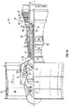
- FIG. 1A schematically illustrates a gas turbine engine 20.
- the exemplary gas turbine engine 20 is a two-spool turbofan engine that generally incorporates a fan section 22, a compressor section 24, a combustor section 26, and a turbine section 28.
- Alternative engines might include an augmenter section (not shown) among other systems for features.
- the fan section 22 drives air along a bypass flow path B, while the compressor section 24 drives air along a core flow path C for compression and communication into the combustor section 26.
- Hot combustion gases generated in the combustor section 26 are expanded through the turbine section 28.
- a turbofan gas turbine engine depicted as a turbofan gas turbine engine in the disclosed non-limiting embodiment, it should be understood that the concepts described herein are not limited to turbofan engines and these teachings could extend to other types of engines, including but not limited to, three-spool engine architectures.
- the gas turbine engine 20 generally includes a low speed spool 30 and a high speed spool 32 mounted for rotation about an engine centerline longitudinal axis A.
- the low speed spool 30 and the high speed spool 32 may be mounted relative to an engine static structure 33 via several bearing systems 31. It should be understood that other bearing systems 31 may alternatively or additionally be provided.
- the low speed spool 30 generally includes an inner shaft 34 that interconnects a fan 36, a low pressure compressor 38 and a low pressure turbine 39.
- the inner shaft 34 can be connected to the fan 36 through a geared architecture 45 to drive the fan 36 at a lower speed than the low speed spool 30.
- the high speed spool 32 includes an outer shaft 35 that interconnects a high pressure compressor 37 and a high pressure turbine 40.
- the inner shaft 34 and the outer shaft 35 are supported at various axial locations by bearing systems 31 positioned within the engine static structure 33.
- a combustor 42 is arranged between the high pressure compressor 37 and the high pressure turbine 40.
- a mid-turbine frame 44 may be arranged generally between the high pressure turbine 40 and the low pressure turbine 39.
- the mid-turbine frame 44 can support one or more bearing systems 31 of the turbine section 28.
- the mid-turbine frame 44 may include one or more airfoils 46 that extend within the core flow path C.
- the inner shaft 34 and the outer shaft 35 are concentric and rotate via the bearing systems 31 about the engine centerline longitudinal axis A, which is co-linear with their longitudinal axes.
- the core airflow is compressed by the low pressure compressor 38 and the high pressure compressor 37, is mixed with fuel and burned in the combustor 42, and is then expanded over the high pressure turbine 40 and the low pressure turbine 39.
- the high pressure turbine 40 and the low pressure turbine 39 rotationally drive the respective high speed spool 32 and the low speed spool 30 in response to the expansion.
- the pressure ratio of the low pressure turbine 39 can be pressure measured prior to the inlet of the low pressure turbine 39 as related to the pressure at the outlet of the low pressure turbine 39 and prior to an exhaust nozzle of the gas turbine engine 20.
- the bypass ratio of the gas turbine engine 20 is greater than about ten (10:1)
- the fan diameter is significantly larger than that of the low pressure compressor 38
- the low pressure turbine 39 has a pressure ratio that is greater than about five (5:1). It should be understood, however, that the above parameters are only examples of one embodiment of a geared architecture engine and that the present disclosure is applicable to other gas turbine engines, including direct drive turbofans.
- TSFC Thrust Specific Fuel Consumption
- Fan Pressure Ratio is the pressure ratio across a blade of the fan section 22 without the use of a Fan Exit Guide Vane system.
- the low Fan Pressure Ratio according to one non-limiting embodiment of the example gas turbine engine 20 is less than 1.45.
- Low Corrected Fan Tip Speed is the actual fan tip speed divided by an industry standard temperature correction of [(T ram ° R)/(518.7° R)] 0.5 ([(T ram ° K)/(288.2° K)] 0.5 ), where T ram represents the ambient temperature in degrees Rankine.
- the Low Corrected Fan Tip Speed according to one non-limiting embodiment of the example gas turbine engine 20 is less than about 1150 fps (351 m/s).
- Each of the compressor section 24 and the turbine section 28 may include alternating rows of rotor assemblies and vane assemblies (shown schematically) that carry airfoils that extend into the core flow path C.
- the rotor assemblies can carry a plurality of rotating blades 25, while each vane assembly can carry a plurality of vanes 27 that extend into the core flow path C.
- the blades 25 of the rotor assemblies create or extract energy (in the form of pressure) from the core airflow that is communicated through the gas turbine engine 20 along the core flow path C.
- the vanes 27 of the vane assemblies direct the core airflow to the blades 25 to either add or extract energy.
- Various components of a gas turbine engine 20 including but not limited to the airfoils of the blades 25 and the vanes 27 of the compressor section 24 and the turbine section 28, may be subjected to repetitive thermal cycling under widely ranging temperatures and pressures.
- the hardware of the turbine section 28 is particularly subjected to relatively extreme operating conditions. Therefore, some components may require internal cooling circuits for cooling the parts during engine operation.
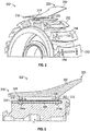
- FIG. 2 illustrated is a perspective view of a fan rotor 202 that may be located within a fan section of a gas turbine engine.
- the fan rotor 202 includes at least one blade root attachment lug 212.
- a fan blade platform 210 is operably coupled to each of the blade root attachment lugs 212.
- each of the blade root attachment lug 212 may include one or more slots 214 that are configured to receive a portion of a platform 210.
- a front end 216 of the platform 210 may include a first connector 218 that may engage within a respective first cavity 214, and at back end 220 of the platform 210, a second connector 222 may engage with a respective second cavity 214.
- a locking pin (not shown) may be used to provide removable attachment between the platform 210 and the blade root attachment lug 212.
- FIG. 3 a cross-sectional schematic view of a portion of a fan rotor 302 is shown. During installation of a fan section of a gas turbine engine, a fan blade platform 310 may be operably coupled to each of the blade root attachment lugs 312 of the fan rotor 302.
- Each platform 310 may include at least one connector, e.g., first connector 318 and second connector 322, extending from a bottom of the platform 310.
- Each of the at least one connectors 318, 322 include an aperture 324, 326, respectively, formed therethrough.
- the first connector 318 is inserted into a first cavity 314a at a front end 316, and the second connector 322 is inserted into a second cavity 314b at a back end 320.
- a pin 328 may be inserted through a blade root attachment lug aperture 330 to pass through each of the apertures 324, 326 of the platform 310 in the first connector 318 and the second connector 322.
- FIGS. 4A and 4B views of a platform 410 in accordance with the invention are shown.
- FIG. 4A is a perspective view of the platform 410 and
- FIG. 4B is a rear elevation view of the platform 410.
- the platform 410 may be installed and operated similar to the platforms described above.
- Platform 410 includes a top wall 411 or flow path surface.
- a first sidewall 432 having two arms 432a, 432b, is located at a front end 416 of the platform 410 and extends downward from the top wall 411.
- a second sidewall 434 having two arms 434a, 434b, is located at a rear end 420 of the platform 410 and extends downward from the top wall 411.
- the top wall 411, the first sidewall 432, and the second sidewall 434 form a unitary body of the platform 410.
- the arms 432a, 432b of the first sidewall 432 join opposite the top wall 411 to form the first connector 418.
- the arms 434a, 434b of the second sidewall 434 join opposite the top wall 411 to form the second connector 422.
- the first connector 418 may define two pin supports 418a and 418b and the second connector 422 may define two pin supports 422a and 422b.
- the pin supports 418a, 418b and 422a, 422b may define apertures 424 and 426, respectively, which receive a locking pin (not shown).
- the sidewalls 432, 434 are bowed or curved, as extending from the top wall 411 to the respective pin supports 418a, 418b and 422a, 422b of the connectors 418, 422, respectively.
- a blend radius 436 (shown in FIG. 4B ) joins the sidewalls 432, 434 to the top wall 411. Under centrifugal loading, an inner surface 438 of the bowed sidewalls 432, 434 may go into tension due to movement inward and upward which in turn decreases the high tensile load through a flow path fillet.
- the bowed sidewalls 432, 434 allow for spreading a bending load over the entire sidewall 432, 434 while also enlarging the available real estate inside the platform for inner mold tooling, especially near the front end 416.
- the bowed sidewalls 432, 434 may further decrease interlaminar stresses to within material tolerances as compared to similar platform designs with straight sidewalls.
- the sidewall 434 define a curvature or contour extending from the top wall 411 to the connector 422. That is, the arms 434a, 434b of the sidewall 434 may bow outward relative to a line extending from an edge of the top wall 411 and the connector 422. Outward, as used herein, is a direction away from an interior of the platform, the interior defined by interior surfaces of the top wall, the sidewalls, and the connector. As such, a straight wall construction is not used, but rather the sidewall 434 is curved.
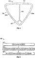
- FIG. 5 an alternative configuration of a platform in accordance with the present disclosure is shown.
- the platform 510 shown in FIG. 5 may be substantially similar to the platform shown in FIGS. 4A and 4B .
- platform 510 includes a top wall 511 with two arms 534a, 534b forming a bowed sidewall 534.
- the two arms 534a, 534b connected with a connector 522.
- the platform 510 includes a stiffener 538 extending from the top wall 511 to the connector 522 at a position between the arms 534a, 534b of the sidewall 534.
- Process 600 may be employed to form a platform such as that shown in FIGS. 4A, 4B , or 5 , having bowed or curved sidewalls.
- a top wall of the platform is formed. This may be casting, molding, additive manufacturing, or other manufacturing technique.
- bowed arms of sidewalls are formed that extend downward from the top wall and extend toward each other.
- the arms of the sidewalls are joined to form a connector below the top wall.
- the connector may be formed with an aperture therethrough that is configured to receive a pin or other locking device.
- blocks 602-606 may be performed simultaneously depending on the manufacturing process, such as in molding, casting, or additive manufacturing.
- the connector may be formed first, and the bowed sidewalls may extend upward and outward therefrom, with the top wall being formed last.
- the order of the blocks 602-606 is not intended to be limiting, but rather is provided as an example manufacturing flow process. Moreover, additional steps and/or processes may be performed without departing from the scope of the present disclosure. For example, one or more stiffeners may be formed in the platform to provide additional structure and/or support to the platform.
- embodiments described herein provide a platform for an airfoil in a gas turbine engine having bowed sidewalls that extend from a top wall of the platform to a pin connector of the platform.
- the bowed sidewalls may provide improved (i.e., decreased) interlaminar stresses within the platform.
- the bowed sidewalls may include a blend radius proximal to the top wall, and thus the stresses may be decreased.
- a central interior area or volume of the platform is shown as hollow or empty (e.g., as shown in FIGS. 4A and 4B ), those of skill in the art will appreciate that one or more vertical stiffeners may be included therein.
- a vertical stiffener may extend from a pin support to an interior surface of the top wall.
Landscapes
- Engineering & Computer Science (AREA)
- Mechanical Engineering (AREA)
- General Engineering & Computer Science (AREA)
- Architecture (AREA)
- Structures Of Non-Positive Displacement Pumps (AREA)
Description
- The subject matter disclosed herein generally relates to airfoil platforms used in gas turbine engines and, more particularly, to airfoil platforms having bowed sidewalls.
- Gas turbine engines generally include a fan section, a compressor section, a combustor section, and turbine sections positioned along a centerline referred to as an "axis of rotation." The fan, compressor, and combustor sections add work to air (also referred to as "core gas") flowing through the engine. The turbine extracts work from the core gas flow to drive the fan and compressor sections. The fan, compressor, and turbine sections each include a series of stator and rotor assemblies. The stator assemblies, which do not rotate (but may have variable pitch vanes), increase the efficiency of the engine by guiding core gas flow into or out of the rotor assemblies.
- The fan section includes a rotor assembly and a stator assembly. The rotor assembly of the fan includes a rotor disk and a plurality of outwardly extending rotor blades. Each rotor blade includes an airfoil portion, a dove-tailed root portion, and a platform. The airfoil portion extends through the flow path and interacts with the working medium gases to transfer energy between the rotor blade and working medium gases. The dove-tailed root portion engages attachment means of the rotor disk. The platform typically extends circumferentially from the rotor blade to a platform of an adjacent rotor blade. The platform is disposed radially between the airfoil portion and the root portion. The stator assembly includes a fan case, which circumscribes the rotor assembly in close proximity to the tips of the rotor blades.
- To reduce the size and cost of the rotor blades, the platform size may be reduced and a separate fan blade platform may be attached to the rotor disk. To accommodate the separate fan blade platforms, outwardly extending tabs may be forged onto the rotor disk to enable attachment of the platforms. Fan platforms having either straight or more than one straight feature joined by blend radii may create high inter-laminar stresses due to high tensile loading through the fillets and a thin, fragile geometry may be needed for internal mold tools.
- According to the invention, a platform for an airfoil in a gas turbine engine is defined in claim 1, the platform comprising: a top wall defining a front end and a back end of the platform and configured to connect to an airfoil of the gas turbine engine; a first connector configured to receive a pin and secure the platform to a rotor of the gas turbine engine; a first sidewall located at the front end and extending from the top wall to the first connector, the first sidewall having a first arm and a second arm, wherein the first arm and the second arm of the first sidewall are curved such that a bowed first sidewall extends from the top wall to the first connector; a second connector configured to receive the pin and secure the platform to the rotor of the gas turbine engine; a second sidewall located at the back end and extending from the top wall to the second connector, the second sidewall having a first arm and a second arm, wherein the first arm and the second arm of the second sidewall are curved such that a bowed second sidewall extends from the top wall to the second connector; and an interior, the interior defined by interior surfaces of the top wall, the first and second sidewalls and the first and
second connectors; and wherein the first arms and the second arms of the first and second sidewalls are bowed outward relative to the interior of the platform. - Further embodiments of the platform may include a blend radius between the first and second sidewalls and the top wall.
- Further embodiments of the platform may include a stiffener extending from the top wall to the first and second connectors and located between the first arm and the second arm of the first and second sidewalls.
- According to the invention, a method of manufacturing a platform for an airfoil in a gas turbine engine is defined in claim 5, the method comprising: forming a top wall defining a front end and a back end of the platform and configured to connect to the airfoil of the gas turbine engine; forming a first sidewall located at the front end and
extending downward from the top wall, the first sidewall having a first arm and a second arm, wherein the first arm and the second arm of the first sidewall are curved such that a bowed first sidewall extends from the top wall downward, with the first arm and the second arm extending toward each other; forming a first connector between the first arm and the second arm of the first sidewall, the first connector configured to receive a pin and secure the platform to a rotor of the gas turbine engine; forming a second sidewall located at the back end and extending downward from the top wall, the second sidewall having a first arm and a second arm, wherein the first arm and the second arm of the second sidewall are curved such that a bowed second sidewall extends from the top wall downward, with the first arm and the second arm extending toward each other; forming a second connector between the first arm and the second arm of the second sidewall, the second connector configured to receive the pin and secure the platform to the rotor of the gas turbine engine; wherein the top wall, the first and second sidewalls, and the first and second connectors define an interior of the platform; and wherein the first arms and the second arms of the first and second sidewalls are bowed relative to the interior of the platform. - Further embodiments of the method may include forming a blend radius between the first and second sidewalls and the top wall.
- Further embodiments of the method may include that the top wall, the first and second sidewalls, and the first and second connectors are formed substantially simultaneously.
- Further embodiments of the method may include that the top wall, the first and second sidewalls, and the first and second connectors are formed by additive manufacturing.
- Further embodiments of the method may include forming a stiffener extending from the top wall to the first and second connectors and located between the first arm and the second arm of the first and second sidewalls.
- According to another embodiment, a gas turbine engine is provided. The engine includes a rotor, at least one airfoil, and a platform according to any of the foregoing embodiments.
- Further embodiments of the engine may include a plurality of airfoils and a plurality of platforms configured to attach to the rotor.
- Embodiments of the present disclosure include a platform used in a gas turbine engine having bowed sidewalls. Further embodiments include a process of manufacturing a platform for a gas turbine engine that includes bowed sidewalls. The foregoing features and elements may be combined in various combinations without exclusivity, unless expressly indicated otherwise. These features and elements as well as the operation thereof will become more apparent in light of the following description and the accompanying drawings. It should be understood, however, that the following description and drawings are intended to be illustrative and explanatory in nature and non-limiting.
- The subject matter is particularly pointed out and distinctly claimed at the conclusion of the specification. The foregoing and other features, and advantages of the present disclosure are apparent from the following detailed description taken in conjunction with the accompanying drawings in which:
-
FIG. 1A is a schematic cross-sectional illustration of a gas turbine engine that may employ various embodiments disclosed herein; -
FIG. 2 is a perspective view of a fan rotor including a plurality of blade root attachment lugs and a blade platform; -
FIG. 3 is a cross-sectional illustration of a blade platform as engaged with a blade root attachment lug; -
FIG. 4A is a perspective schematic illustration of a platform in accordance with an embodiment of the present disclosure; -
FIG. 4B is a rear elevation schematic illustration of the platform ofFIG. 4A ; -
FIG. 5 is a rear elevation schematic illustration of a platform in accordance with another embodiment of the present disclosure; and -
FIG. 6 is a process for manufacturing a platform in accordance with an embodiment of the present disclosure. - As shown and described herein, various features of the disclosure will be presented. Various embodiments may have the same or similar features and thus the same or similar features may be labeled with the same reference numeral, but preceded by a different first number indicating the figure to which the feature is shown. Thus, for example, element "a" that is shown in FIG. X may be labeled "Xa" and a similar feature in FIG. Z may be labeled "Za." Although similar reference numbers may be used in a generic sense, various embodiments will be described and various features may include changes, alterations, modifications, etc. as will be appreciated by those of skill in the art, whether explicitly described or otherwise would be appreciated by those of skill in the art.
-
FIG. 1A schematically illustrates agas turbine engine 20. The exemplarygas turbine engine 20 is a two-spool turbofan engine that generally incorporates a fan section 22, acompressor section 24, acombustor section 26, and aturbine section 28. - Alternative engines might include an augmenter section (not shown) among other systems for features. The fan section 22 drives air along a bypass flow path B, while the
compressor section 24 drives air along a core flow path C for compression and communication into thecombustor section 26. Hot combustion gases generated in thecombustor section 26 are expanded through theturbine section 28. Although depicted as a turbofan gas turbine engine in the disclosed non-limiting embodiment, it should be understood that the concepts described herein are not limited to turbofan engines and these teachings could extend to other types of engines, including but not limited to, three-spool engine architectures. - The
gas turbine engine 20 generally includes alow speed spool 30 and ahigh speed spool 32 mounted for rotation about an engine centerline longitudinal axis A. Thelow speed spool 30 and thehigh speed spool 32 may be mounted relative to an enginestatic structure 33 viaseveral bearing systems 31. It should be understood that other bearingsystems 31 may alternatively or additionally be provided. - The
low speed spool 30 generally includes aninner shaft 34 that interconnects afan 36, alow pressure compressor 38 and alow pressure turbine 39. Theinner shaft 34 can be connected to thefan 36 through a gearedarchitecture 45 to drive thefan 36 at a lower speed than thelow speed spool 30. Thehigh speed spool 32 includes anouter shaft 35 that interconnects ahigh pressure compressor 37 and ahigh pressure turbine 40. In this embodiment, theinner shaft 34 and theouter shaft 35 are supported at various axial locations by bearingsystems 31 positioned within the enginestatic structure 33. - A
combustor 42 is arranged between thehigh pressure compressor 37 and thehigh pressure turbine 40. Amid-turbine frame 44 may be arranged generally between thehigh pressure turbine 40 and thelow pressure turbine 39. Themid-turbine frame 44 can support one ormore bearing systems 31 of theturbine section 28. Themid-turbine frame 44 may include one ormore airfoils 46 that extend within the core flow path C. - The
inner shaft 34 and theouter shaft 35 are concentric and rotate via the bearingsystems 31 about the engine centerline longitudinal axis A, which is co-linear with their longitudinal axes. The core airflow is compressed by thelow pressure compressor 38 and thehigh pressure compressor 37, is mixed with fuel and burned in thecombustor 42, and is then expanded over thehigh pressure turbine 40 and thelow pressure turbine 39. Thehigh pressure turbine 40 and thelow pressure turbine 39 rotationally drive the respectivehigh speed spool 32 and thelow speed spool 30 in response to the expansion. - The pressure ratio of the
low pressure turbine 39 can be pressure measured prior to the inlet of thelow pressure turbine 39 as related to the pressure at the outlet of thelow pressure turbine 39 and prior to an exhaust nozzle of thegas turbine engine 20. In one non-limiting embodiment, the bypass ratio of thegas turbine engine 20 is greater than about ten (10:1), the fan diameter is significantly larger than that of thelow pressure compressor 38, and thelow pressure turbine 39 has a pressure ratio that is greater than about five (5:1). It should be understood, however, that the above parameters are only examples of one embodiment of a geared architecture engine and that the present disclosure is applicable to other gas turbine engines, including direct drive turbofans. - In this embodiment of the example
gas turbine engine 20, a significant amount of thrust is provided by the bypass flow path B due to the high bypass ratio. The fan section 22 of thegas turbine engine 20 is designed for a particular flight condition-typically cruise at about 0.8 Mach and about 35,000 feet (10,668 metres). This flight condition, with thegas turbine engine 20 at its best fuel consumption, is also known as bucket cruise Thrust Specific Fuel Consumption (TSFC). TSFC is an industry standard parameter of fuel consumption per unit of thrust. - Fan Pressure Ratio is the pressure ratio across a blade of the fan section 22 without the use of a Fan Exit Guide Vane system. The low Fan Pressure Ratio according to one non-limiting embodiment of the example
gas turbine engine 20 is less than 1.45. Low Corrected Fan Tip Speed is the actual fan tip speed divided by an industry standard temperature correction of [(Tram ° R)/(518.7° R)]0.5([(Tram ° K)/(288.2° K)]0.5), where Tram represents the ambient temperature in degrees Rankine. The Low Corrected Fan Tip Speed according to one non-limiting embodiment of the examplegas turbine engine 20 is less than about 1150 fps (351 m/s). - Each of the
compressor section 24 and theturbine section 28 may include alternating rows of rotor assemblies and vane assemblies (shown schematically) that carry airfoils that extend into the core flow path C. For example, the rotor assemblies can carry a plurality ofrotating blades 25, while each vane assembly can carry a plurality ofvanes 27 that extend into the core flow path C. Theblades 25 of the rotor assemblies create or extract energy (in the form of pressure) from the core airflow that is communicated through thegas turbine engine 20 along the core flow path C. Thevanes 27 of the vane assemblies direct the core airflow to theblades 25 to either add or extract energy. - Various components of a
gas turbine engine 20, including but not limited to the airfoils of theblades 25 and thevanes 27 of thecompressor section 24 and theturbine section 28, may be subjected to repetitive thermal cycling under widely ranging temperatures and pressures. The hardware of theturbine section 28 is particularly subjected to relatively extreme operating conditions. Therefore, some components may require internal cooling circuits for cooling the parts during engine operation. - Turning now to
FIG. 2 , illustrated is a perspective view of afan rotor 202 that may be located within a fan section of a gas turbine engine. As shown, thefan rotor 202 includes at least one bladeroot attachment lug 212. During installation of the fan section, afan blade platform 210 is operably coupled to each of the blade root attachment lugs 212. As shown, each of the bladeroot attachment lug 212 may include one ormore slots 214 that are configured to receive a portion of aplatform 210. For example, as shown, afront end 216 of theplatform 210 may include afirst connector 218 that may engage within a respectivefirst cavity 214, and atback end 220 of theplatform 210, asecond connector 222 may engage with a respectivesecond cavity 214. A locking pin (not shown) may be used to provide removable attachment between theplatform 210 and the bladeroot attachment lug 212. Turning now toFIG. 3 , a cross-sectional schematic view of a portion of afan rotor 302 is shown. During installation of a fan section of a gas turbine engine, afan blade platform 310 may be operably coupled to each of the blade root attachment lugs 312 of thefan rotor 302. Eachplatform 310 may include at least one connector, e.g.,first connector 318 andsecond connector 322, extending from a bottom of theplatform 310. Each of the at least oneconnectors aperture - To secure the
platform 310 to a respective bladeroot attachment lug 312, thefirst connector 318 is inserted into afirst cavity 314a at afront end 316, and thesecond connector 322 is inserted into asecond cavity 314b at aback end 320. Apin 328 may be inserted through a blade rootattachment lug aperture 330 to pass through each of theapertures platform 310 in thefirst connector 318 and thesecond connector 322. - Turning now to
FIGS. 4A and 4B , views of aplatform 410 in accordance with the invention are shown.FIG. 4A is a perspective view of theplatform 410 andFIG. 4B is a rear elevation view of theplatform 410. Theplatform 410 may be installed and operated similar to the platforms described above. -
Platform 410 includes atop wall 411 or flow path surface. Afirst sidewall 432, having twoarms front end 416 of theplatform 410 and extends downward from thetop wall 411. Asecond sidewall 434, having twoarms rear end 420 of theplatform 410 and extends downward from thetop wall 411. - As shown, the
top wall 411, thefirst sidewall 432, and thesecond sidewall 434 form a unitary body of theplatform 410. Thearms first sidewall 432 join opposite thetop wall 411 to form thefirst connector 418. Similarly, thearms second sidewall 434 join opposite thetop wall 411 to form thesecond connector 422. As shown inFIG. 4A , thefirst connector 418 may define two pin supports 418a and 418b and thesecond connector 422 may define two pin supports 422a and 422b. The pin supports 418a, 418b and 422a, 422b may defineapertures - As shown, the
sidewalls top wall 411 to the respective pin supports 418a, 418b and 422a, 422b of theconnectors FIG. 4B ) joins thesidewalls top wall 411. Under centrifugal loading, aninner surface 438 of the bowed sidewalls 432, 434 may go into tension due to movement inward and upward which in turn decreases the high tensile load through a flow path fillet. The bowed sidewalls 432, 434 allow for spreading a bending load over theentire sidewall front end 416. The bowed sidewalls 432, 434 may further decrease interlaminar stresses to within material tolerances as compared to similar platform designs with straight sidewalls. - As shown in
FIG. 4B , thesidewall 434 define a curvature or contour extending from thetop wall 411 to theconnector 422. That is, thearms sidewall 434 may bow outward relative to a line extending from an edge of thetop wall 411 and theconnector 422. Outward, as used herein, is a direction away from an interior of the platform, the interior defined by interior surfaces of the top wall, the sidewalls, and the connector. As such, a straight wall construction is not used, but rather thesidewall 434 is curved. - Turning now to
FIG. 5 , an alternative configuration of a platform in accordance with the present disclosure is shown. Theplatform 510 shown inFIG. 5 may be substantially similar to the platform shown inFIGS. 4A and 4B . Thus,platform 510 includes atop wall 511 with twoarms sidewall 534. The twoarms connector 522. However, in the embodiment shown inFIG. 5 , theplatform 510 includes astiffener 538 extending from thetop wall 511 to theconnector 522 at a position between thearms sidewall 534. - Turning now to
FIG. 6 , a process of manufacturing a platform in accordance with the invention is shown.Process 600 may be employed to form a platform such as that shown inFIGS. 4A, 4B , or5 , having bowed or curved sidewalls. - At
block 602, a top wall of the platform is formed. This may be casting, molding, additive manufacturing, or other manufacturing technique. Atblock 604, bowed arms of sidewalls are formed that extend downward from the top wall and extend toward each other. Atblock 606, the arms of the sidewalls are joined to form a connector below the top wall. The connector may be formed with an aperture therethrough that is configured to receive a pin or other locking device. As will be appreciated by those of skill in the art, blocks 602-606 may be performed simultaneously depending on the manufacturing process, such as in molding, casting, or additive manufacturing. Further, in some embodiments, the connector may be formed first, and the bowed sidewalls may extend upward and outward therefrom, with the top wall being formed last. Thus, the order of the blocks 602-606 is not intended to be limiting, but rather is provided as an example manufacturing flow process. Moreover, additional steps and/or processes may be performed without departing from the scope of the present disclosure. For example, one or more stiffeners may be formed in the platform to provide additional structure and/or support to the platform. - Advantageously, embodiments described herein provide a platform for an airfoil in a gas turbine engine having bowed sidewalls that extend from a top wall of the platform to a pin connector of the platform. Advantageously, the bowed sidewalls may provide improved (i.e., decreased) interlaminar stresses within the platform. For example, the bowed sidewalls may include a blend radius proximal to the top wall, and thus the stresses may be decreased.
- While the present disclosure has been described in detail in connection with only a limited number of embodiments, it should be readily understood that the present disclosure is not limited to such disclosed embodiments.
- For example, although shown an described with respect to example embodiments, those of skill in the art will appreciate that the configuration and structure of the platforms disclosed herein may be varied without departing from the scope of the present disclosure. For example, although a central interior area or volume of the platform is shown as hollow or empty (e.g., as shown in
FIGS. 4A and 4B ), those of skill in the art will appreciate that one or more vertical stiffeners may be included therein. For example, a vertical stiffener may extend from a pin support to an interior surface of the top wall. - Accordingly, the present disclosure is not to be seen as limited by the foregoing description, but is only limited by the scope of the appended claims.
Claims (9)
- A platform (410; 510) for an airfoil in a gas turbine engine, the platform (410; 510) comprising:a top wall (411; 511) defining a front end (416) and a back end (420) of the platform (410; 510) and configured to connect to an airfoil of the gas turbine engine;a first connector (418) configured to receive a pin and secure the platform (410; 510) to a rotor of the gas turbine engine;a first sidewall (432) located at the front end (416) and extending from the top wall (411; 511) to the first connector (418), the first sidewall (432) having a first arm (432a) and a second arm (432b), wherein the first arm (432a) and the second arm (423b) of the first sidewall (432) are curved such that a bowed first sidewall extends from the top wall (411; 511) to the first connector (418);a second connector (422; 522) configured to receive the pin and secure the platform (410; 510) to the rotor of the gas turbine engine;a second sidewall (434; 534) located at the back end (420) and extending from the top wall (411; 511) to the second connector (422; 522), the second sidewall (434; 534) having a first arm (434a; 534a) and a second arm (434b; 534b), wherein the first arm (434a; 534a) and the second arm (434b; 534b) of the second sidewall (434; 534) are curved such that a bowed second sidewall extends from the top wall (411; 511) to the second connector (422); andan interior, the interior defined by interior surfaces of the top wall (411; 511), the first and second sidewalls (432; 434; 534) and the first and second connectors (418; 422); andwherein the first arms (432a; 434a; 534a) and the second arms (432b; 434b; 534b) of the first and second sidewalls (432; 434; 534) are bowed outward relative to the interior of the platform (410; 510).
- The platform (410; 510) of claim 1, wherein the top wall (411; 511), the first sidewall (432) and the second sidewall (434; 534) form a unitary body.
- The platform (410; 510) of any of the preceding claims, further comprising a blend radius (436) between the first and second sidewalls (432; 434; 534) and the top wall (411; 511).
- The platform (410; 510) of any of the preceding claims, further comprising a stiffener (538) extending from the top wall (411; 511) to the first and second connectors (418; 422; 522) and located between the first arms (432a; 434a; 534a) and the second arms (432b; 434b; 534b) of the first and second sidewalls (432; 434; 534).
- A method of manufacturing a platform (410; 510) for an airfoil in a gas turbine engine, the method comprising:forming a top wall (411; 511) defining a front end (416) and a back end (420) of the platform and configured to connect to the airfoil of the gas turbine engine;forming a first sidewall (432) located at the front end (416) and extending downward from the top wall (411; 511), the first sidewall (432) having a first arm (432a) and a second arm (432b), wherein the first arm (432a) and the second arm (432b) of the first sidewall (432) are curved such that a bowed first sidewall extends from the top wall (411; 511) downward, with the first arm (432a) and the second arm (432b) extending toward each other;forming a first connector (418) between the first arm (432a) and the second arm (432b) of the first sidewall (432), the first connector (418) configured to receive a pin and secure the platform (410; 510) to a rotor of the gas turbine engine;forming a second sidewall (434; 534) located at the back end (420) and extending downward from the top wall (411; 511), the second sidewall (434; 534) having a first arm (434a; 534a) and a second arm (434b; 534b), wherein the first arm (434a; 534a) and the second arm (434b; 534b) of the second sidewall (434; 534) are curved such that a bowed second sidewall extends from the top wall (411; 511) downward, with the first arm (434a; 534a) and the second arm (434b; 534b) extending toward each other;forming a second connector (422; 522) between the first arm (434a; 534a) and the second arm (434b; 534b) of the second sidewall (434; 534), the second connector (422; 522) configured to receive the pin and secure the platform (410; 510) to the rotor of the gas turbine engine;wherein the top wall (411; 511), the first and second sidewalls (432; 434; 534), and the first and second connectors (418; 422) define an interior of the platform (410; 510); andwherein the first arms (432a; 434a; 534a) and the second arms (432b; 434b; 534b) of the first and second sidewalls (432; 434; 534) are bowed outward relative to the interior of the platform (410; 510).
- The method of claim 5, further comprising forming a blend radius (436) between the first and second sidewalls (432; 434; 534) and the top wall (411; 511).
- The method of any of claims 5 or 6, wherein the top wall (411; 511), the first and second sidewalls (432; 434; 534), and the first and second connectors (418; 422; 522) are formed simultaneously.
- The method of any of claims 5, 6 or 7, wherein the top wall (411; 511), the first and second sidewalls (432; 434; 534), and the first and second connectors (418; 422; 522) are formed by additive manufacturing.
- The method of any of claims 5 to 8, further comprising forming a stiffener (538) extending from the top wall (411; 511) to the first and second connectors (418; 422; 522) and located between the first arms (432a; 434a; 534a) and the second arms (432b; 434b; 534b) of the first and second sidewalls (432; 434; 534).
Applications Claiming Priority (1)
| Application Number | Priority Date | Filing Date | Title |
|---|---|---|---|
| US14/948,624 US10584592B2 (en) | 2015-11-23 | 2015-11-23 | Platform for an airfoil having bowed sidewalls |
Publications (2)
| Publication Number | Publication Date |
|---|---|
| EP3170983A1 EP3170983A1 (en) | 2017-05-24 |
| EP3170983B1 true EP3170983B1 (en) | 2020-05-06 |
Family
ID=57391907
Family Applications (1)
| Application Number | Title | Priority Date | Filing Date |
|---|---|---|---|
| EP16200324.8A Active EP3170983B1 (en) | 2015-11-23 | 2016-11-23 | Platform and corresponding method of manufacturing |
Country Status (2)
| Country | Link |
|---|---|
| US (1) | US10584592B2 (en) |
| EP (1) | EP3170983B1 (en) |
Families Citing this family (4)
| Publication number | Priority date | Publication date | Assignee | Title |
|---|---|---|---|---|
| US20170218782A1 (en) * | 2014-08-22 | 2017-08-03 | Siemens Energy, Inc. | Modular turbine blade with separate platform support system |
| US11174741B2 (en) | 2018-04-19 | 2021-11-16 | Raytheon Technologies Corporation | Platform for an airfoil of a gas turbine engine |
| US10557361B1 (en) | 2018-10-16 | 2020-02-11 | United Technologies Corporation | Platform for an airfoil of a gas turbine engine |
| US11815017B2 (en) * | 2020-04-16 | 2023-11-14 | Rtx Corporation | Fan blade platform for gas turbine engine |
Family Cites Families (24)
| Publication number | Priority date | Publication date | Assignee | Title |
|---|---|---|---|---|
| US3294364A (en) * | 1962-01-02 | 1966-12-27 | Gen Electric | Rotor assembly |
| GB1232506A (en) * | 1969-10-28 | 1971-05-19 | ||
| US3694104A (en) * | 1970-10-07 | 1972-09-26 | Garrett Corp | Turbomachinery blade |
| US4621979A (en) * | 1979-11-30 | 1986-11-11 | United Technologies Corporation | Fan rotor blades of turbofan engines |
| US5102302A (en) * | 1988-06-02 | 1992-04-07 | General Electric Company | Fan blade mount |
| FR2639402B1 (en) * | 1988-11-23 | 1990-12-28 | Snecma | TURBOMACHINE ROTOR WING DISC |
| FR2679296B1 (en) * | 1991-07-17 | 1993-10-15 | Snecma | SEPARATE INTER-BLADE PLATFORM FOR TURBOMACHINE ROTOR WING DISC. |
| US5240377A (en) * | 1992-02-25 | 1993-08-31 | Williams International Corporation | Composite fan blade |
| US5281096A (en) * | 1992-09-10 | 1994-01-25 | General Electric Company | Fan assembly having lightweight platforms |
| US6217283B1 (en) * | 1999-04-20 | 2001-04-17 | General Electric Company | Composite fan platform |
| EP1124038A1 (en) * | 2000-02-09 | 2001-08-16 | Siemens Aktiengesellschaft | Turbine blading |
| US6447250B1 (en) * | 2000-11-27 | 2002-09-10 | General Electric Company | Non-integral fan platform |
| FR2858370B1 (en) * | 2003-07-31 | 2005-09-30 | Snecma Moteurs | INTER-AUBES ALLEGEE PLATFORM FOR A TURBOREACTOR BLADE SUPPORT DISK |
| US7878763B2 (en) * | 2007-05-15 | 2011-02-01 | General Electric Company | Turbine rotor blade assembly and method of assembling the same |
| WO2009018145A1 (en) * | 2007-07-27 | 2009-02-05 | Evergreen Solar, Inc. | Wafer/ribbon crystal method and apparatus |
| US8408874B2 (en) | 2008-04-11 | 2013-04-02 | United Technologies Corporation | Platformless turbine blade |
| US8568102B2 (en) * | 2009-02-18 | 2013-10-29 | Pratt & Whitney Canada Corp. | Fan blade anti-fretting insert |
| US8777576B2 (en) * | 2011-08-22 | 2014-07-15 | General Electric Company | Metallic fan blade platform |
| US8939727B2 (en) * | 2011-09-08 | 2015-01-27 | Siemens Energy, Inc. | Turbine blade and non-integral platform with pin attachment |
| US9267386B2 (en) * | 2012-06-29 | 2016-02-23 | United Technologies Corporation | Fairing assembly |
| ITCO20120058A1 (en) * | 2012-12-13 | 2014-06-14 | Nuovo Pignone Srl | METHODS FOR MANUFACTURING BLADES DIVIDED IN TURBOMACCHINE BY ADDITIVE PRODUCTION, TURBOMACCHINA POLES AND TURBOMACHINES |
| US9845699B2 (en) * | 2013-03-15 | 2017-12-19 | Gkn Aerospace Services Structures Corp. | Fan spacer having unitary over molded feature |
| GB201314541D0 (en) * | 2013-08-14 | 2013-09-25 | Rolls Royce Plc | Annulus Filler |
| US9976426B2 (en) | 2015-07-21 | 2018-05-22 | United Technologies Corporation | Fan platform with stiffening feature |
-
2015
- 2015-11-23 US US14/948,624 patent/US10584592B2/en active Active
-
2016
- 2016-11-23 EP EP16200324.8A patent/EP3170983B1/en active Active
Non-Patent Citations (1)
| Title |
|---|
| None * |
Also Published As
| Publication number | Publication date |
|---|---|
| EP3170983A1 (en) | 2017-05-24 |
| US20170145829A1 (en) | 2017-05-25 |
| US10584592B2 (en) | 2020-03-10 |
Similar Documents
| Publication | Publication Date | Title |
|---|---|---|
| EP2948636B1 (en) | Gas turbine engine component having contoured rib end | |
| EP3170981B1 (en) | An airfoil comprising a baffle, a gas turbine engine, and a method of repairing an airfoil | |
| EP3064711B1 (en) | Component for a gas turbine engine, corresponding gas turbine engine and method of forming an airfoil | |
| US10612392B2 (en) | Gas turbine engine component with conformal fillet cooling path | |
| EP3505726B1 (en) | Vane assembly for a gas turbine engine | |
| EP3118414B1 (en) | Gas turbine engine airfoil | |
| US10927682B2 (en) | Engine component with non-diffusing section | |
| EP3094823B1 (en) | Gas turbine engine component and corresponding gas turbine engine | |
| EP3170983B1 (en) | Platform and corresponding method of manufacturing | |
| US20140109548A1 (en) | High pressure rotor disk | |
| EP3170984B1 (en) | Platform and corresponding method of manufacturing | |
| EP3047111B1 (en) | Component for a gas turbine engine, corresponding gas turbine engine and method of cooling | |
| EP2993303B1 (en) | Gas turbine engine component with film cooling hole with pocket | |
| US20150354372A1 (en) | Gas turbine engine component with angled aperture impingement | |
| EP3045666B1 (en) | Airfoil platform with cooling feed orifices | |
| EP3037627A1 (en) | Hardware geometry for increasing part overlap and maintaining clearance | |
| EP3061913B1 (en) | Gas turbine engine airfoil cooling configuration with pressure gradient separators | |
| US11168571B2 (en) | Airfoil having dead-end tip flag cavity | |
| US20180038236A1 (en) | Gas turbine engine stator vane baffle arrangement | |
| EP3623575B1 (en) | Serpentine turn cover for gas turbine stator vane assembly | |
| EP3333365B1 (en) | Stator with support structure feature for tuned airfoil | |
| EP2977557B1 (en) | Cooled airfoil structure and corresponding cooling method | |
| EP3121377A1 (en) | Turbine rotors including turbine blades having turbulator cooled tip pockets |
Legal Events
| Date | Code | Title | Description |
|---|---|---|---|
| PUAI | Public reference made under article 153(3) epc to a published international application that has entered the european phase |
Free format text: ORIGINAL CODE: 0009012 |
|
| STAA | Information on the status of an ep patent application or granted ep patent |
Free format text: STATUS: THE APPLICATION HAS BEEN PUBLISHED |
|
| AK | Designated contracting states |
Kind code of ref document: A1 Designated state(s): AL AT BE BG CH CY CZ DE DK EE ES FI FR GB GR HR HU IE IS IT LI LT LU LV MC MK MT NL NO PL PT RO RS SE SI SK SM TR |
|
| AX | Request for extension of the european patent |
Extension state: BA ME |
|
| RIN1 | Information on inventor provided before grant (corrected) |
Inventor name: TATTON, ROYCE E. |
|
| STAA | Information on the status of an ep patent application or granted ep patent |
Free format text: STATUS: REQUEST FOR EXAMINATION WAS MADE |
|
| 17P | Request for examination filed |
Effective date: 20171124 |
|
| RBV | Designated contracting states (corrected) |
Designated state(s): AL AT BE BG CH CY CZ DE DK EE ES FI FR GB GR HR HU IE IS IT LI LT LU LV MC MK MT NL NO PL PT RO RS SE SI SK SM TR |
|
| STAA | Information on the status of an ep patent application or granted ep patent |
Free format text: STATUS: EXAMINATION IS IN PROGRESS |
|
| 17Q | First examination report despatched |
Effective date: 20180702 |
|
| REG | Reference to a national code |
Ref country code: DE Ref legal event code: R079 Ref document number: 602016035613 Country of ref document: DE Free format text: PREVIOUS MAIN CLASS: F01D0005300000 Ipc: F01D0011000000 |
|
| GRAP | Despatch of communication of intention to grant a patent |
Free format text: ORIGINAL CODE: EPIDOSNIGR1 |
|
| RIC1 | Information provided on ipc code assigned before grant |
Ipc: F01D 11/00 20060101AFI20191128BHEP Ipc: F01D 5/30 20060101ALN20191128BHEP |
|
| STAA | Information on the status of an ep patent application or granted ep patent |
Free format text: STATUS: GRANT OF PATENT IS INTENDED |
|
| RIC1 | Information provided on ipc code assigned before grant |
Ipc: F01D 11/00 20060101AFI20191205BHEP Ipc: F01D 5/30 20060101ALN20191205BHEP |
|
| INTG | Intention to grant announced |
Effective date: 20200102 |
|
| GRAS | Grant fee paid |
Free format text: ORIGINAL CODE: EPIDOSNIGR3 |
|
| GRAA | (expected) grant |
Free format text: ORIGINAL CODE: 0009210 |
|
| STAA | Information on the status of an ep patent application or granted ep patent |
Free format text: STATUS: THE PATENT HAS BEEN GRANTED |
|
| AK | Designated contracting states |
Kind code of ref document: B1 Designated state(s): AL AT BE BG CH CY CZ DE DK EE ES FI FR GB GR HR HU IE IS IT LI LT LU LV MC MK MT NL NO PL PT RO RS SE SI SK SM TR |
|
| REG | Reference to a national code |
Ref country code: GB Ref legal event code: FG4D |
|
| REG | Reference to a national code |
Ref country code: CH Ref legal event code: EP Ref country code: AT Ref legal event code: REF Ref document number: 1267040 Country of ref document: AT Kind code of ref document: T Effective date: 20200515 |
|
| REG | Reference to a national code |
Ref country code: IE Ref legal event code: FG4D |
|
| REG | Reference to a national code |
Ref country code: DE Ref legal event code: R096 Ref document number: 602016035613 Country of ref document: DE |
|
| REG | Reference to a national code |
Ref country code: LT Ref legal event code: MG4D |
|
| REG | Reference to a national code |
Ref country code: NL Ref legal event code: MP Effective date: 20200506 |
|
| PG25 | Lapsed in a contracting state [announced via postgrant information from national office to epo] |
Ref country code: IS Free format text: LAPSE BECAUSE OF FAILURE TO SUBMIT A TRANSLATION OF THE DESCRIPTION OR TO PAY THE FEE WITHIN THE PRESCRIBED TIME-LIMIT Effective date: 20200906 Ref country code: FI Free format text: LAPSE BECAUSE OF FAILURE TO SUBMIT A TRANSLATION OF THE DESCRIPTION OR TO PAY THE FEE WITHIN THE PRESCRIBED TIME-LIMIT Effective date: 20200506 Ref country code: PT Free format text: LAPSE BECAUSE OF FAILURE TO SUBMIT A TRANSLATION OF THE DESCRIPTION OR TO PAY THE FEE WITHIN THE PRESCRIBED TIME-LIMIT Effective date: 20200907 Ref country code: LT Free format text: LAPSE BECAUSE OF FAILURE TO SUBMIT A TRANSLATION OF THE DESCRIPTION OR TO PAY THE FEE WITHIN THE PRESCRIBED TIME-LIMIT Effective date: 20200506 Ref country code: GR Free format text: LAPSE BECAUSE OF FAILURE TO SUBMIT A TRANSLATION OF THE DESCRIPTION OR TO PAY THE FEE WITHIN THE PRESCRIBED TIME-LIMIT Effective date: 20200807 Ref country code: SE Free format text: LAPSE BECAUSE OF FAILURE TO SUBMIT A TRANSLATION OF THE DESCRIPTION OR TO PAY THE FEE WITHIN THE PRESCRIBED TIME-LIMIT Effective date: 20200506 Ref country code: NO Free format text: LAPSE BECAUSE OF FAILURE TO SUBMIT A TRANSLATION OF THE DESCRIPTION OR TO PAY THE FEE WITHIN THE PRESCRIBED TIME-LIMIT Effective date: 20200806 |
|
| PG25 | Lapsed in a contracting state [announced via postgrant information from national office to epo] |
Ref country code: BG Free format text: LAPSE BECAUSE OF FAILURE TO SUBMIT A TRANSLATION OF THE DESCRIPTION OR TO PAY THE FEE WITHIN THE PRESCRIBED TIME-LIMIT Effective date: 20200806 Ref country code: RS Free format text: LAPSE BECAUSE OF FAILURE TO SUBMIT A TRANSLATION OF THE DESCRIPTION OR TO PAY THE FEE WITHIN THE PRESCRIBED TIME-LIMIT Effective date: 20200506 Ref country code: HR Free format text: LAPSE BECAUSE OF FAILURE TO SUBMIT A TRANSLATION OF THE DESCRIPTION OR TO PAY THE FEE WITHIN THE PRESCRIBED TIME-LIMIT Effective date: 20200506 Ref country code: LV Free format text: LAPSE BECAUSE OF FAILURE TO SUBMIT A TRANSLATION OF THE DESCRIPTION OR TO PAY THE FEE WITHIN THE PRESCRIBED TIME-LIMIT Effective date: 20200506 |
|
| REG | Reference to a national code |
Ref country code: AT Ref legal event code: MK05 Ref document number: 1267040 Country of ref document: AT Kind code of ref document: T Effective date: 20200506 |
|
| PG25 | Lapsed in a contracting state [announced via postgrant information from national office to epo] |
Ref country code: AL Free format text: LAPSE BECAUSE OF FAILURE TO SUBMIT A TRANSLATION OF THE DESCRIPTION OR TO PAY THE FEE WITHIN THE PRESCRIBED TIME-LIMIT Effective date: 20200506 Ref country code: NL Free format text: LAPSE BECAUSE OF FAILURE TO SUBMIT A TRANSLATION OF THE DESCRIPTION OR TO PAY THE FEE WITHIN THE PRESCRIBED TIME-LIMIT Effective date: 20200506 |
|
| PG25 | Lapsed in a contracting state [announced via postgrant information from national office to epo] |
Ref country code: EE Free format text: LAPSE BECAUSE OF FAILURE TO SUBMIT A TRANSLATION OF THE DESCRIPTION OR TO PAY THE FEE WITHIN THE PRESCRIBED TIME-LIMIT Effective date: 20200506 Ref country code: DK Free format text: LAPSE BECAUSE OF FAILURE TO SUBMIT A TRANSLATION OF THE DESCRIPTION OR TO PAY THE FEE WITHIN THE PRESCRIBED TIME-LIMIT Effective date: 20200506 Ref country code: AT Free format text: LAPSE BECAUSE OF FAILURE TO SUBMIT A TRANSLATION OF THE DESCRIPTION OR TO PAY THE FEE WITHIN THE PRESCRIBED TIME-LIMIT Effective date: 20200506 Ref country code: SM Free format text: LAPSE BECAUSE OF FAILURE TO SUBMIT A TRANSLATION OF THE DESCRIPTION OR TO PAY THE FEE WITHIN THE PRESCRIBED TIME-LIMIT Effective date: 20200506 Ref country code: IT Free format text: LAPSE BECAUSE OF FAILURE TO SUBMIT A TRANSLATION OF THE DESCRIPTION OR TO PAY THE FEE WITHIN THE PRESCRIBED TIME-LIMIT Effective date: 20200506 Ref country code: CZ Free format text: LAPSE BECAUSE OF FAILURE TO SUBMIT A TRANSLATION OF THE DESCRIPTION OR TO PAY THE FEE WITHIN THE PRESCRIBED TIME-LIMIT Effective date: 20200506 Ref country code: RO Free format text: LAPSE BECAUSE OF FAILURE TO SUBMIT A TRANSLATION OF THE DESCRIPTION OR TO PAY THE FEE WITHIN THE PRESCRIBED TIME-LIMIT Effective date: 20200506 Ref country code: ES Free format text: LAPSE BECAUSE OF FAILURE TO SUBMIT A TRANSLATION OF THE DESCRIPTION OR TO PAY THE FEE WITHIN THE PRESCRIBED TIME-LIMIT Effective date: 20200506 |
|
| REG | Reference to a national code |
Ref country code: DE Ref legal event code: R097 Ref document number: 602016035613 Country of ref document: DE |
|
| PG25 | Lapsed in a contracting state [announced via postgrant information from national office to epo] |
Ref country code: PL Free format text: LAPSE BECAUSE OF FAILURE TO SUBMIT A TRANSLATION OF THE DESCRIPTION OR TO PAY THE FEE WITHIN THE PRESCRIBED TIME-LIMIT Effective date: 20200506 Ref country code: SK Free format text: LAPSE BECAUSE OF FAILURE TO SUBMIT A TRANSLATION OF THE DESCRIPTION OR TO PAY THE FEE WITHIN THE PRESCRIBED TIME-LIMIT Effective date: 20200506 |
|
| PLBE | No opposition filed within time limit |
Free format text: ORIGINAL CODE: 0009261 |
|
| STAA | Information on the status of an ep patent application or granted ep patent |
Free format text: STATUS: NO OPPOSITION FILED WITHIN TIME LIMIT |
|
| RAP2 | Party data changed (patent owner data changed or rights of a patent transferred) |
Owner name: RAYTHEON TECHNOLOGIES CORPORATION |
|
| 26N | No opposition filed |
Effective date: 20210209 |
|
| PG25 | Lapsed in a contracting state [announced via postgrant information from national office to epo] |
Ref country code: SI Free format text: LAPSE BECAUSE OF FAILURE TO SUBMIT A TRANSLATION OF THE DESCRIPTION OR TO PAY THE FEE WITHIN THE PRESCRIBED TIME-LIMIT Effective date: 20200506 |
|
| PG25 | Lapsed in a contracting state [announced via postgrant information from national office to epo] |
Ref country code: MC Free format text: LAPSE BECAUSE OF FAILURE TO SUBMIT A TRANSLATION OF THE DESCRIPTION OR TO PAY THE FEE WITHIN THE PRESCRIBED TIME-LIMIT Effective date: 20200506 |
|
| REG | Reference to a national code |
Ref country code: CH Ref legal event code: PL |
|
| PG25 | Lapsed in a contracting state [announced via postgrant information from national office to epo] |
Ref country code: LU Free format text: LAPSE BECAUSE OF NON-PAYMENT OF DUE FEES Effective date: 20201123 |
|
| REG | Reference to a national code |
Ref country code: BE Ref legal event code: MM Effective date: 20201130 |
|
| PG25 | Lapsed in a contracting state [announced via postgrant information from national office to epo] |
Ref country code: CH Free format text: LAPSE BECAUSE OF NON-PAYMENT OF DUE FEES Effective date: 20201130 Ref country code: LI Free format text: LAPSE BECAUSE OF NON-PAYMENT OF DUE FEES Effective date: 20201130 |
|
| PG25 | Lapsed in a contracting state [announced via postgrant information from national office to epo] |
Ref country code: IE Free format text: LAPSE BECAUSE OF NON-PAYMENT OF DUE FEES Effective date: 20201123 |
|
| PG25 | Lapsed in a contracting state [announced via postgrant information from national office to epo] |
Ref country code: TR Free format text: LAPSE BECAUSE OF FAILURE TO SUBMIT A TRANSLATION OF THE DESCRIPTION OR TO PAY THE FEE WITHIN THE PRESCRIBED TIME-LIMIT Effective date: 20200506 Ref country code: MT Free format text: LAPSE BECAUSE OF FAILURE TO SUBMIT A TRANSLATION OF THE DESCRIPTION OR TO PAY THE FEE WITHIN THE PRESCRIBED TIME-LIMIT Effective date: 20200506 Ref country code: CY Free format text: LAPSE BECAUSE OF FAILURE TO SUBMIT A TRANSLATION OF THE DESCRIPTION OR TO PAY THE FEE WITHIN THE PRESCRIBED TIME-LIMIT Effective date: 20200506 |
|
| PG25 | Lapsed in a contracting state [announced via postgrant information from national office to epo] |
Ref country code: MK Free format text: LAPSE BECAUSE OF FAILURE TO SUBMIT A TRANSLATION OF THE DESCRIPTION OR TO PAY THE FEE WITHIN THE PRESCRIBED TIME-LIMIT Effective date: 20200506 |
|
| PG25 | Lapsed in a contracting state [announced via postgrant information from national office to epo] |
Ref country code: BE Free format text: LAPSE BECAUSE OF NON-PAYMENT OF DUE FEES Effective date: 20201130 |
|
| REG | Reference to a national code |
Ref country code: DE Ref legal event code: R081 Ref document number: 602016035613 Country of ref document: DE Owner name: RAYTHEON TECHNOLOGIES CORPORATION (N.D.GES.D.S, US Free format text: FORMER OWNER: UNITED TECHNOLOGIES CORPORATION, FARMINGTON, CONN., US Ref country code: DE Ref legal event code: R081 Ref document number: 602016035613 Country of ref document: DE Owner name: RTX CORPORATION (N.D.GES.D. STAATES DELAWARE),, US Free format text: FORMER OWNER: UNITED TECHNOLOGIES CORPORATION, FARMINGTON, CONN., US |
|
| P01 | Opt-out of the competence of the unified patent court (upc) registered |
Effective date: 20230520 |
|
| REG | Reference to a national code |
Ref country code: DE Ref legal event code: R081 Ref document number: 602016035613 Country of ref document: DE Owner name: RTX CORPORATION (N.D.GES.D. STAATES DELAWARE),, US Free format text: FORMER OWNER: RAYTHEON TECHNOLOGIES CORPORATION (N.D.GES.D.STAATES DELAWARE), ARLINGTON, VA, US |
|
| PGFP | Annual fee paid to national office [announced via postgrant information from national office to epo] |
Ref country code: DE Payment date: 20251022 Year of fee payment: 10 |
|
| PGFP | Annual fee paid to national office [announced via postgrant information from national office to epo] |
Ref country code: GB Payment date: 20251023 Year of fee payment: 10 |
|
| PGFP | Annual fee paid to national office [announced via postgrant information from national office to epo] |
Ref country code: FR Payment date: 20251022 Year of fee payment: 10 |