EP3170979A1 - Turbine component including mixed cooling nub feature - Google Patents
Turbine component including mixed cooling nub feature Download PDFInfo
- Publication number
- EP3170979A1 EP3170979A1 EP16199681.4A EP16199681A EP3170979A1 EP 3170979 A1 EP3170979 A1 EP 3170979A1 EP 16199681 A EP16199681 A EP 16199681A EP 3170979 A1 EP3170979 A1 EP 3170979A1
- Authority
- EP
- European Patent Office
- Prior art keywords
- cooling
- nubs
- component
- cooled
- nub
- Prior art date
- Legal status (The legal status is an assumption and is not a legal conclusion. Google has not performed a legal analysis and makes no representation as to the accuracy of the status listed.)
- Granted
Links
Images
Classifications
-
- F—MECHANICAL ENGINEERING; LIGHTING; HEATING; WEAPONS; BLASTING
- F02—COMBUSTION ENGINES; HOT-GAS OR COMBUSTION-PRODUCT ENGINE PLANTS
- F02C—GAS-TURBINE PLANTS; AIR INTAKES FOR JET-PROPULSION PLANTS; CONTROLLING FUEL SUPPLY IN AIR-BREATHING JET-PROPULSION PLANTS
- F02C7/00—Features, components parts, details or accessories, not provided for in, or of interest apart form groups F02C1/00 - F02C6/00; Air intakes for jet-propulsion plants
- F02C7/12—Cooling of plants
- F02C7/16—Cooling of plants characterised by cooling medium
- F02C7/18—Cooling of plants characterised by cooling medium the medium being gaseous, e.g. air
-
- F—MECHANICAL ENGINEERING; LIGHTING; HEATING; WEAPONS; BLASTING
- F01—MACHINES OR ENGINES IN GENERAL; ENGINE PLANTS IN GENERAL; STEAM ENGINES
- F01D—NON-POSITIVE DISPLACEMENT MACHINES OR ENGINES, e.g. STEAM TURBINES
- F01D5/00—Blades; Blade-carrying members; Heating, heat-insulating, cooling or antivibration means on the blades or the members
- F01D5/12—Blades
- F01D5/14—Form or construction
- F01D5/18—Hollow blades, i.e. blades with cooling or heating channels or cavities; Heating, heat-insulating or cooling means on blades
- F01D5/187—Convection cooling
-
- F—MECHANICAL ENGINEERING; LIGHTING; HEATING; WEAPONS; BLASTING
- F02—COMBUSTION ENGINES; HOT-GAS OR COMBUSTION-PRODUCT ENGINE PLANTS
- F02C—GAS-TURBINE PLANTS; AIR INTAKES FOR JET-PROPULSION PLANTS; CONTROLLING FUEL SUPPLY IN AIR-BREATHING JET-PROPULSION PLANTS
- F02C7/00—Features, components parts, details or accessories, not provided for in, or of interest apart form groups F02C1/00 - F02C6/00; Air intakes for jet-propulsion plants
- F02C7/12—Cooling of plants
-
- F—MECHANICAL ENGINEERING; LIGHTING; HEATING; WEAPONS; BLASTING
- F05—INDEXING SCHEMES RELATING TO ENGINES OR PUMPS IN VARIOUS SUBCLASSES OF CLASSES F01-F04
- F05D—INDEXING SCHEME FOR ASPECTS RELATING TO NON-POSITIVE-DISPLACEMENT MACHINES OR ENGINES, GAS-TURBINES OR JET-PROPULSION PLANTS
- F05D2240/00—Components
- F05D2240/80—Platforms for stationary or moving blades
- F05D2240/81—Cooled platforms
-
- F—MECHANICAL ENGINEERING; LIGHTING; HEATING; WEAPONS; BLASTING
- F05—INDEXING SCHEMES RELATING TO ENGINES OR PUMPS IN VARIOUS SUBCLASSES OF CLASSES F01-F04
- F05D—INDEXING SCHEME FOR ASPECTS RELATING TO NON-POSITIVE-DISPLACEMENT MACHINES OR ENGINES, GAS-TURBINES OR JET-PROPULSION PLANTS
- F05D2250/00—Geometry
- F05D2250/10—Two-dimensional
- F05D2250/18—Two-dimensional patterned
-
- F—MECHANICAL ENGINEERING; LIGHTING; HEATING; WEAPONS; BLASTING
- F05—INDEXING SCHEMES RELATING TO ENGINES OR PUMPS IN VARIOUS SUBCLASSES OF CLASSES F01-F04
- F05D—INDEXING SCHEME FOR ASPECTS RELATING TO NON-POSITIVE-DISPLACEMENT MACHINES OR ENGINES, GAS-TURBINES OR JET-PROPULSION PLANTS
- F05D2250/00—Geometry
- F05D2250/20—Three-dimensional
- F05D2250/28—Three-dimensional patterned
-
- F—MECHANICAL ENGINEERING; LIGHTING; HEATING; WEAPONS; BLASTING
- F05—INDEXING SCHEMES RELATING TO ENGINES OR PUMPS IN VARIOUS SUBCLASSES OF CLASSES F01-F04
- F05D—INDEXING SCHEME FOR ASPECTS RELATING TO NON-POSITIVE-DISPLACEMENT MACHINES OR ENGINES, GAS-TURBINES OR JET-PROPULSION PLANTS
- F05D2260/00—Function
- F05D2260/20—Heat transfer, e.g. cooling
- F05D2260/221—Improvement of heat transfer
- F05D2260/2214—Improvement of heat transfer by increasing the heat transfer surface
-
- Y—GENERAL TAGGING OF NEW TECHNOLOGICAL DEVELOPMENTS; GENERAL TAGGING OF CROSS-SECTIONAL TECHNOLOGIES SPANNING OVER SEVERAL SECTIONS OF THE IPC; TECHNICAL SUBJECTS COVERED BY FORMER USPC CROSS-REFERENCE ART COLLECTIONS [XRACs] AND DIGESTS
- Y02—TECHNOLOGIES OR APPLICATIONS FOR MITIGATION OR ADAPTATION AGAINST CLIMATE CHANGE
- Y02T—CLIMATE CHANGE MITIGATION TECHNOLOGIES RELATED TO TRANSPORTATION
- Y02T50/00—Aeronautics or air transport
- Y02T50/60—Efficient propulsion technologies, e.g. for aircraft
Definitions
- the present disclosure relates generally to cooling features for gas turbine engine components, and more specifically to a mixed cooling nub feature for the same.
- Components within gas turbine engines such as aircraft engines, land based turbines, and the like, are frequently exposed to high temperatures due to the operation of the gas turbine engine. In order to mitigate the effects of the high temperatures, some components are exposed to cooling flows and convective heat transfer from the component to the cooling flow cools the component.
- the cooling flow continuously cycles a coolant, such as air, over one or more surface of the component.
- a coolant such as air
- the cycling of the coolant removes the warmed coolant and replaces the warmed coolant with a cooled coolant.
- the warmed coolant is passed to a cooler, alternately referred to as a condenser, where it is cooled and returned to the coolant flow.
- cooled coolant is drawn from a supply, passed over the component and expelled.
- a component for a gas turbine engine includes at least one cooled surface configured to contact a cooling flow, the at least one cooled surface having a base surface and a plurality of cooling nubs disposed about the base surface, and the plurality of cooling nubs are distributed about the base surface in a mixed pattern.
- the mixed pattern includes a non-uniform distance between each cooling nub and each adjacent cooling nub.
- the mixed pattern includes a combination of at least two sizes of cooling nubs.
- the mixed pattern further includes a non-uniform distance between each cooling nub and each adjacent cooling nub.
- the mixed pattern further includes at least two distinct cooling nub geometries.
- the at least two distinct cooling nub geometries include at least one of: multiple distinct cross sectional geometries and multiple distinct geometrical configurations.
- each of the at least one cooled surfaces is a single cast component, and each of the cooling nubs is integral to the base surface.
- the cast component includes post-cast finishing.
- a surface area of the base surface and a surface area of each of the cooling nubs is a convective cooling surface.
- At least one of the cooled surfaces is a recessed surface, and wherein the mixed pattern of cooling nubs includes cooling nubs having a first size and cooling nubs having a second size smaller than the first size.
- cooling nubs within a predetermined distance of an edge of the recessed surface are the second size.
- the cooling nubs extend outward from the cooled surface into the cooling flow.
- a gas turbine engine includes a compressor section, a combustor section fluidly connected to the compressor section, a turbine section fluidly connected to the combustor section, and at least one convectively cooled component within the gas turbine engine, the convectively cooled component including at least one cooled surface configured to contact a cooling flow, the at least one cooled surface including a plurality of cooling nubs arranged in a mixed pattern.
- the mixed pattern includes at least one of a non-uniform distance between each cooling nub and each adjacent cooling nub and a combination of at least two sizes of cooling nubs.
- the mixed pattern further includes at least two distinct cooling nub geometries.
- the at least two distinct cooling nub geometries include at least one of: multiple distinct cross sectional geometries and multiple distinct geometrical configurations.
- each of the at least one cooled surfaces is a single cast component, and each of the cooling nubs is integral to the cooled surface.
- the at least one cooled surface includes a surface recessed into the convectively cooled component.
- An exemplary method of enhancing cooling for a gas turbine engine component includes disposing a plurality of cooling nubs on a cooled surface according to a mixed pattern including at least one of multiple distinct sizes of cooling nubs, a varied concentration of cooling nubs, and a varied geometry of cooling nubs.
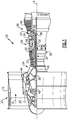
- FIG. 1 schematically illustrates a gas turbine engine 20.
- the gas turbine engine 20 is disclosed herein as a two-spool turbofan that generally incorporates a fan section 22, a compressor section 24, a combustor section 26 and a turbine section 28.
- Alternative engines might include an augmentor section (not shown) among other systems or features.
- the fan section 22 drives air along a bypass flow path B in a bypass duct defined within a nacelle 15, while the compressor section 24 drives air along a core flow path C for compression and communication into the combustor section 26 then expansion through the turbine section 28.
- the exemplary engine 20 generally includes a low speed spool 30 and a high speed spool 32 mounted for rotation about an engine central longitudinal axis A relative to an engine static structure 36 via several bearing systems 38. It should be understood that various bearing systems 38 at various locations may alternatively or additionally be provided, and the location of bearing systems 38 may be varied as appropriate to the application.
- the low speed spool 30 generally includes an inner shaft 40 that interconnects a fan 42, a first (or low) pressure compressor 44 and a first (or low) pressure turbine 46.
- the inner shaft 40 is connected to the fan 42 through a speed change mechanism, which in exemplary gas turbine engine 20 is illustrated as a geared architecture 48 to drive the fan 42 at a lower speed than the low speed spool 30.
- the high speed spool 32 includes an outer shaft 50 that interconnects a second (or high) pressure compressor 52 and a second (or high) pressure turbine 54.
- a combustor 56 is arranged in exemplary gas turbine 20 between the high pressure compressor 52 and the high pressure turbine 54.
- a mid-turbine frame 57 of the engine static structure 36 is arranged generally between the high pressure turbine 54 and the low pressure turbine 46.
- the mid-turbine frame 57 further supports bearing systems 38 in the turbine section 28.
- the inner shaft 40 and the outer shaft 50 are concentric and rotate via bearing systems 38 about the engine central longitudinal axis A which is collinear with their longitudinal axes.
- the core airflow is compressed by the low pressure compressor 44 then the high pressure compressor 52, mixed and burned with fuel in the combustor 56, then expanded over the high pressure turbine 54 and low pressure turbine 46.
- the mid-turbine frame 57 includes airfoils 59 which are in the core airflow path C.
- the turbines 46, 54 rotationally drive the respective low speed spool 30 and high speed spool 32 in response to the expansion.
- gear system 48 may be located aft of combustor section 26 or even aft of turbine section 28, and fan section 22 may be positioned forward or aft of the location of gear system 48.
- Gas turbine engines such as the exemplary gas turbine engine described above and illustrated in Figure 1 , include sections that are subjected to extreme heat during operation of the gas turbine engine.
- the components are actively cooled using a cooling system built into the gas turbine engine.
- some or all of a component is cooled by passing a cooled fluid (referred to as a coolant) over one or more surfaces of the component.
- the coolant flow absorbs heat from the surface of the component that is exposed to the coolant flow in a convective cooling manner.
- the coolant flow can be generated using any known cooling system including open loop cooling systems and closed loop cooling systems.
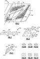
- FIG. 2 schematically illustrates a partial view of a gas turbine engine component 100 cooled using convective cooling.
- the component 100 includes a complex geometry having at least one cooled surface 110.
- the cooled surface 110 is recessed relative to one or more adjacent surfaces.
- a cooling flow 102 passes across the component 100 and contacts the cooling surfaces 110. Heat is removed from the component 100 into the cooling flow 102 via conduction.
- the cooled surface 110 includes multiple cooling nubs 122, 124 distributed across the surface 110.
- the cooling nubs 122, 124 are extensions of the cooled surface that protrude into the cooling flow 102.
- the cooling nubs 122, 124 can be distributed unevenly across the cooled surface 110, and can be unevenly sized.
- the cooling nubs 122, 124 can further be different geometric shapes, depending on the features needed at a given portion of the surface 110. The lack of uniformity in size, shape and/or positioning of the cooling nubs 122, 124 is referred to herein as a "mixed pattern.”
- FIG. 3 schematically illustrates a partial cross sectional view of a cooled surface 210.
- a cooling flow 202 passes across the cooled surface 210 and allows for convective cooling, as described above.
- Each of the cooling nubs 222, 224 extends outward from the base portion of the surface 210 into the cooling flow 202.
- the surface area of the cooled surface 210 is increased by the surface area of the sides 230 of the cooling nubs 222, 224.
- the larger the cooling nub 222, 224 the larger the additional surface area created by the cooling nubs 222, 224.
- the larger the surface area of the cooled surface 210 the larger the magnitude of heat transferred from the component 200 into the cooling flow 202.
- the size of the cooling nub 222, 224 is limited by the geometry of the component 200 or of adjacent parts within the gas turbine engine. In such examples, some portions of the surface can utilize smaller nubs 222 while other portions utilize larger nubs 224.
- the smaller nubs 222 allow the nubs 222 to be positioned closer to an edge of the cooled surface 210, and are shorter, causing less interference with adjacent components within the gas turbine engine.
- the component including the cooled surface 210 can include cast features, or be a single cast component.
- one or more of the cooled surfaces 210 is a cast feature, with the cooling nubs 222, 224 being cast integral to the cooled surface 210. Due to the nature of the cooling nubs 222, 224, the larger cooling nubs 224 are unable to be properly cast adjacent to, or within a certain distance of, the edges of the cooled surface 210 using some casting techniques.
- the utilization of mixed size cooling nubs 222, 224 allows for an increased number of cooling nubs 222, 224 by allowing smaller nubs 222 to be positioned at the edge of the cooled surface 210, where larger nubs 224 are unable to be positioned.
- certain regions of the cooled surface 110, 210 can benefit from additional cooling relative to a remainder of the cooled surface 110, 210.
- An additional cooling requirement in one region is referred to as a localized cooling requirement.
- the cooling nubs 222, 224 are arranged, in some examples, with a greater concentration of the cooling nubs 222, 224 in the region(s) requiring greater cooling.
- Figure 4 schematically illustrates a top view of a cooled surface 310 of a gas turbine engine component. Protruding from the cooled surface 310 are multiple cooling nubs 324.
- each of the cooling nubs 324 is the same size and shape as each other of the cooling nubs 324.
- different sized nubs, or different geometry nubs can be intermixed with the cooling nubs 324 to further enhance localized cooling.
- the cooled surface 310 includes a first region 360 and a second region 362 where increased cooling, relative to a remainder of the cooled surface 310, is required.
- a distance 354 between the cooling nubs 324 and each adjacent cooling nub 324 is decreased relative to the distance 352 between the cooling nubs 324 outside of the regions 360 requiring increased cooling.
- the distance 356 between the cooling nubs 324 is reduced even further.
- the cooled surface 310 can include features that prevent ideal sized cooling nubs from being positioned near or adjacent to an edge of the cooling surface.
- the cooled surface 310 is indented into an edge or surface of the component, such as is the case with a recessed surface, cooling nubs near the edge of the cooled surface 310 can undesirably merge with the edge during some casting processes.
- Figure 5 illustrates one such example cooling surface 410.
- the cooling surface 410 includes acute angled corners 412. Due to the acute angle of the corners and the desired casting process, large cooling nubs 424 cannot be positioned near the acute angle corners 412.
- the mixed pattern of cooling nubs 422, 424 includes smaller cooling nubs 422 capable of being cast without interfering with the edge of the cooling surface 410.
- a distance 452 between each cooling nub 422, 424 and each cooling nub 422, 424 of similar size is uniform across the cooling surface. In alternative examples, the distance 452 can be varied to allow for localized increased cooling as described above with regards to Figure 4 .
- cooling nubs can be any cast shape.
- Figure 6 illustrates three potential cooling nub cross sections 6A, 6B, 6C.
- the illustrated cross sections are exemplary, and one of skill in the art will appreciate that any cast shape can be suitable as a cooling nub shape.
- Nub 6A has a rectangular cross section
- nub 6B has a hemispherical cross section
- nub 6C has a triangular cross section.
- each of the cross sections 6A, 6B, 6C has advantages and disadvantages relative to the other cross sections 6A, 6B, 6C.
- the triangular cross section 6C has the lowest increase in surface area, and thus the least increase in effective cooling, however the triangular cross section also utilizes the least amount of material and has the lowest weight of the illustrated cross sections.
- the rectangular cross section has the largest increase in surface area but the largest accompanying increase in material and weight.
- the cooling nubs can have different geometric configurations designed to conform with, or otherwise adapt to, the geometric configuration of the cooled surface.
- Figure 6 illustrates top views of three exemplary geometric configurations 7A, 7B, 7C.
- 7A illustrates the hemispherical configuration described and illustrated in Figures 2-5.
- 7B illustrates a curved configuration.
- 7C illustrates an s-shaped configuration.
- the varied geometric configurations affect the flow of coolant over the cooled surface in known manners, and a specific configuration can be chosen to achieve desired flow parameters.
- the geometric configuration can be altered to better fit limited constraints of specific cooled surfaces and component designs, and are not limited to the illustrated examples of Figure 7 .
- the cooling nubs on a given cooled surface can be a mixture of multiple different geometric configurations and cross section shapes depending on the needs of a specific implementation.
- cooling nubs protruding outward form a surface While described above as cooling nubs protruding outward form a surface, one of skill in the art having the benefit of this disclosure will understand that the cooling nubs can, in examples with a sufficiently angled cooling flow, be inverted and protrude inward into the surface. In such an example, a single cooled surface could utilize only inverted cooling nubs, or a mixture of standard cooling nubs and inverted cooling nubs.
Landscapes
- Engineering & Computer Science (AREA)
- Chemical & Material Sciences (AREA)
- Combustion & Propulsion (AREA)
- Mechanical Engineering (AREA)
- General Engineering & Computer Science (AREA)
- Turbine Rotor Nozzle Sealing (AREA)
Abstract
Description
- The present disclosure relates generally to cooling features for gas turbine engine components, and more specifically to a mixed cooling nub feature for the same.
- Components within gas turbine engines, such as aircraft engines, land based turbines, and the like, are frequently exposed to high temperatures due to the operation of the gas turbine engine. In order to mitigate the effects of the high temperatures, some components are exposed to cooling flows and convective heat transfer from the component to the cooling flow cools the component.
- The cooling flow continuously cycles a coolant, such as air, over one or more surface of the component. The cycling of the coolant removes the warmed coolant and replaces the warmed coolant with a cooled coolant. In a closed loop coolant system, the warmed coolant is passed to a cooler, alternately referred to as a condenser, where it is cooled and returned to the coolant flow. In an open loop cooling system, cooled coolant is drawn from a supply, passed over the component and expelled.
- In one exemplary embodiment a component for a gas turbine engine includes at least one cooled surface configured to contact a cooling flow, the at least one cooled surface having a base surface and a plurality of cooling nubs disposed about the base surface, and the plurality of cooling nubs are distributed about the base surface in a mixed pattern.
- In an exemplary embodiment of the above described component for a gas turbine engine the mixed pattern includes a non-uniform distance between each cooling nub and each adjacent cooling nub.
- In another exemplary embodiment of any of the above described components for a gas turbine engine the mixed pattern includes a combination of at least two sizes of cooling nubs.
- In another exemplary embodiment of any of the above described components for a gas turbine engine the mixed pattern further includes a non-uniform distance between each cooling nub and each adjacent cooling nub.
- In another exemplary embodiment of any of the above described components for a gas turbine engine the mixed pattern further includes at least two distinct cooling nub geometries.
- In another exemplary embodiment of any of the above described components for a gas turbine engine the at least two distinct cooling nub geometries include at least one of: multiple distinct cross sectional geometries and multiple distinct geometrical configurations.
- In another exemplary embodiment of any of the above described components for a gas turbine engine each of the at least one cooled surfaces is a single cast component, and each of the cooling nubs is integral to the base surface.
- In another exemplary embodiment of any of the above described components for a gas turbine engine the cast component includes post-cast finishing.
- In another exemplary embodiment of any of the above described components for a gas turbine engine a surface area of the base surface and a surface area of each of the cooling nubs is a convective cooling surface.
- In another exemplary embodiment of any of the above described components for a gas turbine engine at least one of the cooled surfaces is a recessed surface, and wherein the mixed pattern of cooling nubs includes cooling nubs having a first size and cooling nubs having a second size smaller than the first size.
- In another exemplary embodiment of any of the above described components for a gas turbine engine cooling nubs within a predetermined distance of an edge of the recessed surface are the second size.
- In another exemplary embodiment of any of the above described components for a gas turbine engine the cooling nubs extend outward from the cooled surface into the cooling flow.
- In one exemplary embodiment a gas turbine engine includes a compressor section, a combustor section fluidly connected to the compressor section, a turbine section fluidly connected to the combustor section, and at least one convectively cooled component within the gas turbine engine, the convectively cooled component including at least one cooled surface configured to contact a cooling flow, the at least one cooled surface including a plurality of cooling nubs arranged in a mixed pattern.
- In an exemplary embodiment of the above described gas turbine engine the mixed pattern includes at least one of a non-uniform distance between each cooling nub and each adjacent cooling nub and a combination of at least two sizes of cooling nubs.
- In another exemplary embodiment of any of the above described gas turbine engines the mixed pattern further includes at least two distinct cooling nub geometries.
- In another exemplary embodiment of any of the above described gas turbine engines the at least two distinct cooling nub geometries include at least one of: multiple distinct cross sectional geometries and multiple distinct geometrical configurations.
- In another exemplary embodiment of any of the above described gas turbine engines each of the at least one cooled surfaces is a single cast component, and each of the cooling nubs is integral to the cooled surface.
- In another exemplary embodiment of any of the above described gas turbine engines the at least one cooled surface includes a surface recessed into the convectively cooled component.
- An exemplary method of enhancing cooling for a gas turbine engine component includes disposing a plurality of cooling nubs on a cooled surface according to a mixed pattern including at least one of multiple distinct sizes of cooling nubs, a varied concentration of cooling nubs, and a varied geometry of cooling nubs.
- In an example of the above described exemplary method of enhancing cooling for a gas turbine engine component disposing a plurality of cooling nubs on the cooled surface includes casting the cooled surface and the cooling nubs as a single integral element.
- These and other features of the present invention can be best understood from the following specification and drawings, the following of which is a brief description.
-
-
Figure 1 schematically illustrates an exemplary gas turbine engine. -
Figure 2 schematically illustrates a partial view of a gas turbine engine component. -
Figure 3 schematically illustrates a cross sectional view of a portion of a gas turbine engine component. -
Figure 4 schematically illustrates a top view of a cooled surface of a gas turbine engine component. -
Figure 5 schematically illustrates a top view of an alternate cooled surface of a gas turbine engine component. -
Figure 6A schematically illustrates a cross sectional view of an exemplary cooling nub geometry. -
Figure 6B schematically illustrates a cross sectional view of an exemplary cooling nub geometry. -
Figure 6C schematically illustrates a cross sectional view of an exemplary cooling nub geometry. -
Figure 7A schematically illustrates a top view of an exemplary cooling nub geometry. -
Figure 7B schematically illustrates a top view of an exemplary cooling nub geometry. -
Figure 7C schematically illustrates a top view of an exemplary cooling nub geometry. -
Figure 1 schematically illustrates agas turbine engine 20. Thegas turbine engine 20 is disclosed herein as a two-spool turbofan that generally incorporates afan section 22, acompressor section 24, a combustor section 26 and aturbine section 28. Alternative engines might include an augmentor section (not shown) among other systems or features. Thefan section 22 drives air along a bypass flow path B in a bypass duct defined within anacelle 15, while thecompressor section 24 drives air along a core flow path C for compression and communication into the combustor section 26 then expansion through theturbine section 28. Although depicted as a two-spool turbofan gas turbine engine in the disclosed non-limiting embodiment, it should be understood that the concepts described herein are not limited to use with two-spool turbofans as the teachings may be applied to other types of turbine engines including three-spool architectures. - The
exemplary engine 20 generally includes alow speed spool 30 and ahigh speed spool 32 mounted for rotation about an engine central longitudinal axis A relative to an enginestatic structure 36 viaseveral bearing systems 38. It should be understood thatvarious bearing systems 38 at various locations may alternatively or additionally be provided, and the location ofbearing systems 38 may be varied as appropriate to the application. - The
low speed spool 30 generally includes aninner shaft 40 that interconnects afan 42, a first (or low)pressure compressor 44 and a first (or low)pressure turbine 46. Theinner shaft 40 is connected to thefan 42 through a speed change mechanism, which in exemplarygas turbine engine 20 is illustrated as a gearedarchitecture 48 to drive thefan 42 at a lower speed than thelow speed spool 30. Thehigh speed spool 32 includes anouter shaft 50 that interconnects a second (or high)pressure compressor 52 and a second (or high)pressure turbine 54. Acombustor 56 is arranged inexemplary gas turbine 20 between thehigh pressure compressor 52 and thehigh pressure turbine 54. Amid-turbine frame 57 of the enginestatic structure 36 is arranged generally between thehigh pressure turbine 54 and thelow pressure turbine 46. Themid-turbine frame 57 further supports bearingsystems 38 in theturbine section 28. Theinner shaft 40 and theouter shaft 50 are concentric and rotate viabearing systems 38 about the engine central longitudinal axis A which is collinear with their longitudinal axes. - The core airflow is compressed by the
low pressure compressor 44 then thehigh pressure compressor 52, mixed and burned with fuel in thecombustor 56, then expanded over thehigh pressure turbine 54 andlow pressure turbine 46. Themid-turbine frame 57 includesairfoils 59 which are in the core airflow path C. Theturbines low speed spool 30 andhigh speed spool 32 in response to the expansion. It will be appreciated that each of the positions of thefan section 22,compressor section 24, combustor section 26,turbine section 28, and fandrive gear system 48 may be varied. For example,gear system 48 may be located aft of combustor section 26 or even aft ofturbine section 28, andfan section 22 may be positioned forward or aft of the location ofgear system 48. - Gas turbine engines, such as the exemplary gas turbine engine described above and illustrated in
Figure 1 , include sections that are subjected to extreme heat during operation of the gas turbine engine. In order to prevent components subjected to the extreme heat from being damaged or from having a decreased component life, the components are actively cooled using a cooling system built into the gas turbine engine. In one example, some or all of a component is cooled by passing a cooled fluid (referred to as a coolant) over one or more surfaces of the component. The coolant flow absorbs heat from the surface of the component that is exposed to the coolant flow in a convective cooling manner. The coolant flow can be generated using any known cooling system including open loop cooling systems and closed loop cooling systems. -
Figure 2 schematically illustrates a partial view of a gasturbine engine component 100 cooled using convective cooling. Thecomponent 100 includes a complex geometry having at least one cooledsurface 110. In the illustrated example, the cooledsurface 110 is recessed relative to one or more adjacent surfaces. Acooling flow 102 passes across thecomponent 100 and contacts the cooling surfaces 110. Heat is removed from thecomponent 100 into thecooling flow 102 via conduction. The amount of heat that is removed can be expressed as Q=hA(Tw-Tc), where h is the local heat transfer coefficient of the cooledsurface 110, A is the surface area of the cooledsurface 110, Tw is the temperature of the cooledsurface 110, TC is the temperature of the coolant, and Q is the magnitude of heat removed from thecomponent 100 via thecooling flow 102. - One of skill in the art will appreciate that the magnitude of heat removed from the
component 100 is directly proportional to the surface area (hA) of the cooledsurface 110. In order to increase the surface area of the cooledsurface 110 that is exposed to thecooling flow 102, the cooledsurface 110 includes multiple coolingnubs surface 110. The coolingnubs cooling flow 102. As can be seen in the example ofFigure 2 , the coolingnubs surface 110, and can be unevenly sized. In alternative examples, the coolingnubs surface 110. The lack of uniformity in size, shape and/or positioning of the coolingnubs - With continued reference to
Figure 2 , and with like numerals indicating like elements,Figure 3 schematically illustrates a partial cross sectional view of a cooledsurface 210. Acooling flow 202 passes across the cooledsurface 210 and allows for convective cooling, as described above. Each of the coolingnubs surface 210 into thecooling flow 202. By extending the coolingnubs cooling flow 202, the surface area of the cooledsurface 210 is increased by the surface area of thesides 230 of the coolingnubs cooling nub nubs surface 210, the larger the magnitude of heat transferred from thecomponent 200 into thecooling flow 202. - In certain examples, and with certain components, the size of the
cooling nub component 200 or of adjacent parts within the gas turbine engine. In such examples, some portions of the surface can utilizesmaller nubs 222 while other portions utilizelarger nubs 224. Thesmaller nubs 222 allow thenubs 222 to be positioned closer to an edge of the cooledsurface 210, and are shorter, causing less interference with adjacent components within the gas turbine engine. - Further, in some examples the component including the cooled
surface 210 can include cast features, or be a single cast component. In such examples, one or more of the cooled surfaces 210 is a cast feature, with the coolingnubs surface 210. Due to the nature of the coolingnubs larger cooling nubs 224 are unable to be properly cast adjacent to, or within a certain distance of, the edges of the cooledsurface 210 using some casting techniques. In such examples, the utilization of mixedsize cooling nubs nubs smaller nubs 222 to be positioned at the edge of the cooledsurface 210, wherelarger nubs 224 are unable to be positioned. - In some examples, certain regions of the cooled
surface surface surface 210, the coolingnubs nubs - With continued reference to
Figures 2 and 3 , and with like numerals indicating like elements,Figure 4 schematically illustrates a top view of a cooledsurface 310 of a gas turbine engine component. Protruding from the cooledsurface 310 are multiple coolingnubs 324. In the illustrated example ofFigure 4 , each of the coolingnubs 324 is the same size and shape as each other of the coolingnubs 324. In alternative examples, different sized nubs, or different geometry nubs can be intermixed with the coolingnubs 324 to further enhance localized cooling. - The cooled
surface 310 includes afirst region 360 and asecond region 362 where increased cooling, relative to a remainder of the cooledsurface 310, is required. In thefirst region 360, adistance 354 between the coolingnubs 324 and eachadjacent cooling nub 324 is decreased relative to thedistance 352 between the coolingnubs 324 outside of theregions 360 requiring increased cooling. In thesecond region 362 requiring increased cooling, thedistance 356 between the coolingnubs 324 is reduced even further. As a result of the illustrated mixed pattern nub configuration ofFigure 4 , both the first andsecond regions surface 310, and the second region is further cooled more than thefirst region 360. - In alternative examples, the cooled
surface 310 can include features that prevent ideal sized cooling nubs from being positioned near or adjacent to an edge of the cooling surface. By way of example, if the cooledsurface 310 is indented into an edge or surface of the component, such as is the case with a recessed surface, cooling nubs near the edge of the cooledsurface 310 can undesirably merge with the edge during some casting processes. - With continued reference to
Figures 2-4, Figure 5 illustrates one suchexample cooling surface 410. The coolingsurface 410 includes acuteangled corners 412. Due to the acute angle of the corners and the desired casting process,large cooling nubs 424 cannot be positioned near theacute angle corners 412. In order to increase the cooling at the acuteangled corners 412, the mixed pattern of coolingnubs smaller cooling nubs 422 capable of being cast without interfering with the edge of thecooling surface 410. In some examples adistance 452 between each coolingnub nub distance 452 can be varied to allow for localized increased cooling as described above with regards toFigure 4 . - While illustrated above as hemispherical nubs in the examples of
Figures 2-5 , the cooling nubs can be any cast shape. With continued reference toFigures 2-5, Figure 6 illustrates three potential cooling nub cross sections 6A, 6B, 6C. The illustrated cross sections are exemplary, and one of skill in the art will appreciate that any cast shape can be suitable as a cooling nub shape. Nub 6A has a rectangular cross section, nub 6B has a hemispherical cross section, and nub 6C has a triangular cross section. - Each of the cross sections 6A, 6B, 6C has advantages and disadvantages relative to the other cross sections 6A, 6B, 6C. By way of example, the triangular cross section 6C has the lowest increase in surface area, and thus the least increase in effective cooling, however the triangular cross section also utilizes the least amount of material and has the lowest weight of the illustrated cross sections. In contrast, the rectangular cross section has the largest increase in surface area but the largest accompanying increase in material and weight.
- In yet further examples, the cooling nubs can have different geometric configurations designed to conform with, or otherwise adapt to, the geometric configuration of the cooled surface. With continued reference to
Figures 2-6, Figure 6 illustrates top views of three exemplary geometric configurations 7A, 7B, 7C. 7A illustrates the hemispherical configuration described and illustrated inFigures 2-5. 7B illustrates a curved configuration. 7C illustrates an s-shaped configuration. The varied geometric configurations affect the flow of coolant over the cooled surface in known manners, and a specific configuration can be chosen to achieve desired flow parameters. - In further examples, the geometric configuration can be altered to better fit limited constraints of specific cooled surfaces and component designs, and are not limited to the illustrated examples of
Figure 7 . Further, the cooling nubs on a given cooled surface can be a mixture of multiple different geometric configurations and cross section shapes depending on the needs of a specific implementation. - While described individually above, one of skill in the art will understand that the described mixed patterns of nubs can be used in combination with any number of the other described mixed patterns and still fall within the instant disclosure.
- Further, while described above as cooling nubs protruding outward form a surface, one of skill in the art having the benefit of this disclosure will understand that the cooling nubs can, in examples with a sufficiently angled cooling flow, be inverted and protrude inward into the surface. In such an example, a single cooled surface could utilize only inverted cooling nubs, or a mixture of standard cooling nubs and inverted cooling nubs.
- It is further understood that any of the above described concepts can be used alone or in combination with any or all of the other above described concepts. Although an embodiment of this invention has been disclosed, a worker of ordinary skill in this art would recognize that certain modifications would come within the scope of this invention. For that reason, the following claims should be studied to determine the true scope and content of this invention.
Claims (15)
- A component (100; 200) for a gas turbine engine comprising:at least one cooled surface (110; 210; 310; 410) configured to contact a cooling flow (102; 202);the at least one cooled surface (110...410) having a base surface and a plurality of cooling nubs (122, 124; 222, 224; 324; 422, 424) disposed about the base surface; andthe plurality of cooling nubs (122...424) are distributed about said base surface in a mixed pattern.
- The component of claim 1, wherein said mixed pattern includes a non-uniform distance (352, 354, 356; 452) between each cooling nub (122...424) and each adjacent cooling nub (122...424).
- The component of claim 1, wherein said mixed pattern includes a combination of at least two sizes of cooling nubs (122...424).
- The component of claim 3, wherein said mixed pattern further includes a non-uniform distance (352...452) between each cooling nub (122...424) and each adjacent cooling nub (122...424).
- The component of any preceding claim, wherein said mixed pattern further includes at least two distinct cooling nub geometries.
- The component of claim 5, wherein said at least two distinct cooling nub geometries include at least one of: multiple distinct cross sectional geometries and multiple distinct geometrical configurations.
- The component of any preceding claim, wherein each of said at least one cooled surfaces (110...410) is a single cast component, and each of said cooling nubs (122...424) is integral to said base surface.
- The component of claim 7, wherein said cast component includes post-cast finishing.
- The component of any preceding claim, wherein a surface area of said base surface and a surface area of each of said cooling nubs (122...424) is a convective cooling surface.
- The component of any preceding claim, wherein at least one of said cooled surfaces (110...410) is a recessed surface, and wherein the mixed pattern of cooling nubs (122...424) includes cooling nubs (122...424) having a first size (124; 224; 424) and cooling nubs (122...424) having a second size (122; 222; 422) smaller than the first size (124; 224; 424).
- The component of claim 10, wherein cooling nubs (122...424) within a predetermined distance of an edge (412) of said recessed surface are said second size (122; 222; 422).
- The component of any preceding claim, wherein the cooling nubs (122...424) extend outward from said cooled surface (110...410) into said cooling flow (102; 202).
- A gas turbine engine (20) comprising:a compressor section (24);a combustor section (26) fluidly connected to the compressor section (24);a turbine section (28) fluidly connected to the combustor section (26); andat least one component (100; 200) of any preceding claim within said gas turbine engine (20), wherein the at least one component (100; 200) is convectively cooled.
- A method of enhancing cooling for a gas turbine engine component (100; 200) comprising:disposing a plurality of cooling nubs (122...424) on a cooled surface (110...410) according to a mixed pattern including at least one of multiple distinct sizes of cooling nubs (122...424), a varied concentration of cooling nubs (122...424), and a varied geometry of cooling nubs (122...424).
- The method of claim 14, wherein disposing a plurality of cooling nubs (122...424) on the cooled surface (110...410) comprises casting the cooled surface (110...410) and the cooling nubs (122...424) as a single integral element.
Applications Claiming Priority (1)
| Application Number | Priority Date | Filing Date | Title |
|---|---|---|---|
| US14/945,939 US10208671B2 (en) | 2015-11-19 | 2015-11-19 | Turbine component including mixed cooling nub feature |
Publications (2)
| Publication Number | Publication Date |
|---|---|
| EP3170979A1 true EP3170979A1 (en) | 2017-05-24 |
| EP3170979B1 EP3170979B1 (en) | 2020-01-01 |
Family
ID=57348598
Family Applications (1)
| Application Number | Title | Priority Date | Filing Date |
|---|---|---|---|
| EP16199681.4A Active EP3170979B1 (en) | 2015-11-19 | 2016-11-18 | Turbine component including mixed cooling nub feature |
Country Status (2)
| Country | Link |
|---|---|
| US (1) | US10208671B2 (en) |
| EP (1) | EP3170979B1 (en) |
Citations (6)
| Publication number | Priority date | Publication date | Assignee | Title |
|---|---|---|---|---|
| US4017213A (en) * | 1975-10-14 | 1977-04-12 | United Technologies Corporation | Turbomachinery vane or blade with cooled platforms |
| US20060093480A1 (en) * | 2004-11-02 | 2006-05-04 | United Technologies Corporation | Airfoil with three-pass serpentine cooling channel and microcircuit |
| EP2602439A1 (en) * | 2011-11-21 | 2013-06-12 | Siemens Aktiengesellschaft | Coolable hot gas component for a gas turbine |
| US20140112799A1 (en) * | 2012-10-23 | 2014-04-24 | Ching-Pang Lee | Cooling arrangement for a gas turbine component |
| US20140321980A1 (en) * | 2013-04-29 | 2014-10-30 | Ching-Pang Lee | Cooling system including wavy cooling chamber in a trailing edge portion of an airfoil assembly |
| EP2927430A1 (en) * | 2014-04-04 | 2015-10-07 | United Technologies Corporation | Stator vane with a cooled platform for a gas turbine engine |
Family Cites Families (13)
| Publication number | Priority date | Publication date | Assignee | Title |
|---|---|---|---|---|
| US4515523A (en) * | 1983-10-28 | 1985-05-07 | Westinghouse Electric Corp. | Cooling arrangement for airfoil stator vane trailing edge |
| US5700132A (en) * | 1991-12-17 | 1997-12-23 | General Electric Company | Turbine blade having opposing wall turbulators |
| US5695320A (en) * | 1991-12-17 | 1997-12-09 | General Electric Company | Turbine blade having auxiliary turbulators |
| US5738493A (en) * | 1997-01-03 | 1998-04-14 | General Electric Company | Turbulator configuration for cooling passages of an airfoil in a gas turbine engine |
| US6155778A (en) | 1998-12-30 | 2000-12-05 | General Electric Company | Recessed turbine shroud |
| US7681398B2 (en) * | 2006-11-17 | 2010-03-23 | Pratt & Whitney Canada Corp. | Combustor liner and heat shield assembly |
| US7722315B2 (en) | 2006-11-30 | 2010-05-25 | General Electric Company | Method and system to facilitate preferentially distributed recuperated film cooling of turbine shroud assembly |
| US7704039B1 (en) | 2007-03-21 | 2010-04-27 | Florida Turbine Technologies, Inc. | BOAS with multiple trenched film cooling slots |
| EP2397653A1 (en) * | 2010-06-17 | 2011-12-21 | Siemens Aktiengesellschaft | Platform segment for supporting a nozzle guide vane for a gas turbine and method of cooling thereof |
| US8814518B2 (en) * | 2010-10-29 | 2014-08-26 | General Electric Company | Apparatus and methods for cooling platform regions of turbine rotor blades |
| US8876458B2 (en) | 2011-01-25 | 2014-11-04 | United Technologies Corporation | Blade outer air seal assembly and support |
| US8840371B2 (en) * | 2011-10-07 | 2014-09-23 | General Electric Company | Methods and systems for use in regulating a temperature of components |
| WO2014151299A1 (en) | 2013-03-15 | 2014-09-25 | United Technologies Corporation | Gas turbine engine turbine vane rail seal |
-
2015
- 2015-11-19 US US14/945,939 patent/US10208671B2/en active Active
-
2016
- 2016-11-18 EP EP16199681.4A patent/EP3170979B1/en active Active
Patent Citations (6)
| Publication number | Priority date | Publication date | Assignee | Title |
|---|---|---|---|---|
| US4017213A (en) * | 1975-10-14 | 1977-04-12 | United Technologies Corporation | Turbomachinery vane or blade with cooled platforms |
| US20060093480A1 (en) * | 2004-11-02 | 2006-05-04 | United Technologies Corporation | Airfoil with three-pass serpentine cooling channel and microcircuit |
| EP2602439A1 (en) * | 2011-11-21 | 2013-06-12 | Siemens Aktiengesellschaft | Coolable hot gas component for a gas turbine |
| US20140112799A1 (en) * | 2012-10-23 | 2014-04-24 | Ching-Pang Lee | Cooling arrangement for a gas turbine component |
| US20140321980A1 (en) * | 2013-04-29 | 2014-10-30 | Ching-Pang Lee | Cooling system including wavy cooling chamber in a trailing edge portion of an airfoil assembly |
| EP2927430A1 (en) * | 2014-04-04 | 2015-10-07 | United Technologies Corporation | Stator vane with a cooled platform for a gas turbine engine |
Also Published As
| Publication number | Publication date |
|---|---|
| EP3170979B1 (en) | 2020-01-01 |
| US10208671B2 (en) | 2019-02-19 |
| US20170145922A1 (en) | 2017-05-25 |
Similar Documents
| Publication | Publication Date | Title |
|---|---|---|
| US10316668B2 (en) | Gas turbine engine component having curved turbulator | |
| EP3081755B1 (en) | Gas turbine engine component with integrated heat pipe | |
| EP2900963B1 (en) | Modulated turbine vane cooling | |
| US10215051B2 (en) | Gas turbine engine component providing prioritized cooling | |
| EP2948636B1 (en) | Gas turbine engine component having contoured rib end | |
| EP3196414B1 (en) | Dual-fed airfoil tip | |
| US10156157B2 (en) | S-shaped trip strips in internally cooled components | |
| EP3128130B1 (en) | Partial cavity baffles for airfoils in gas turbine engines | |
| US20180320530A1 (en) | Airfoil with tip rail cooling | |
| US20100054953A1 (en) | Airfoil with leading edge cooling passage | |
| US20140178174A1 (en) | Gas turbine engine including a pre-diffuser heat exchanger | |
| EP3118414B1 (en) | Gas turbine engine airfoil | |
| EP3290639B1 (en) | Impingement cooling with increased cross-flow area | |
| EP3816407A1 (en) | Impingement cooling with impingement cells on impinged surface | |
| US20140000283A1 (en) | Cover plate for a component of a gas turbine engine | |
| EP3354853B1 (en) | Turbine blade with slot film cooling and manufacturing method | |
| US10329932B2 (en) | Baffle inserts | |
| US20160003053A1 (en) | Gas turbine engine component having transversely angled impingement ribs | |
| US20150110611A1 (en) | Airfoil cooling circuit and corresponding airfoil | |
| EP3047111B1 (en) | Component for a gas turbine engine, corresponding gas turbine engine and method of cooling | |
| EP2948634B1 (en) | Gas turbine engine component with angled aperture impingement | |
| EP3170979B1 (en) | Turbine component including mixed cooling nub feature | |
| EP2998512A1 (en) | Film cooled components and corresponding operating method |
Legal Events
| Date | Code | Title | Description |
|---|---|---|---|
| PUAI | Public reference made under article 153(3) epc to a published international application that has entered the european phase |
Free format text: ORIGINAL CODE: 0009012 |
|
| STAA | Information on the status of an ep patent application or granted ep patent |
Free format text: STATUS: THE APPLICATION HAS BEEN PUBLISHED |
|
| AK | Designated contracting states |
Kind code of ref document: A1 Designated state(s): AL AT BE BG CH CY CZ DE DK EE ES FI FR GB GR HR HU IE IS IT LI LT LU LV MC MK MT NL NO PL PT RO RS SE SI SK SM TR |
|
| AX | Request for extension of the european patent |
Extension state: BA ME |
|
| STAA | Information on the status of an ep patent application or granted ep patent |
Free format text: STATUS: REQUEST FOR EXAMINATION WAS MADE |
|
| 17P | Request for examination filed |
Effective date: 20171124 |
|
| RBV | Designated contracting states (corrected) |
Designated state(s): AL AT BE BG CH CY CZ DE DK EE ES FI FR GB GR HR HU IE IS IT LI LT LU LV MC MK MT NL NO PL PT RO RS SE SI SK SM TR |
|
| GRAP | Despatch of communication of intention to grant a patent |
Free format text: ORIGINAL CODE: EPIDOSNIGR1 |
|
| STAA | Information on the status of an ep patent application or granted ep patent |
Free format text: STATUS: GRANT OF PATENT IS INTENDED |
|
| RIC1 | Information provided on ipc code assigned before grant |
Ipc: F02C 7/18 20060101ALI20190517BHEP Ipc: F01D 5/18 20060101AFI20190517BHEP Ipc: F02C 7/12 20060101ALI20190517BHEP |
|
| INTG | Intention to grant announced |
Effective date: 20190613 |
|
| RIN1 | Information on inventor provided before grant (corrected) |
Inventor name: AUXIER, JAMES T Inventor name: MCGINNIS, CHRISTINE F. Inventor name: MENTZ, KARL A. |
|
| GRAS | Grant fee paid |
Free format text: ORIGINAL CODE: EPIDOSNIGR3 |
|
| GRAA | (expected) grant |
Free format text: ORIGINAL CODE: 0009210 |
|
| STAA | Information on the status of an ep patent application or granted ep patent |
Free format text: STATUS: THE PATENT HAS BEEN GRANTED |
|
| AK | Designated contracting states |
Kind code of ref document: B1 Designated state(s): AL AT BE BG CH CY CZ DE DK EE ES FI FR GB GR HR HU IE IS IT LI LT LU LV MC MK MT NL NO PL PT RO RS SE SI SK SM TR |
|
| REG | Reference to a national code |
Ref country code: GB Ref legal event code: FG4D |
|
| REG | Reference to a national code |
Ref country code: CH Ref legal event code: EP Ref country code: AT Ref legal event code: REF Ref document number: 1220017 Country of ref document: AT Kind code of ref document: T Effective date: 20200115 |
|
| REG | Reference to a national code |
Ref country code: IE Ref legal event code: FG4D |
|
| REG | Reference to a national code |
Ref country code: DE Ref legal event code: R096 Ref document number: 602016027224 Country of ref document: DE |
|
| REG | Reference to a national code |
Ref country code: NL Ref legal event code: MP Effective date: 20200101 |
|
| REG | Reference to a national code |
Ref country code: LT Ref legal event code: MG4D |
|
| PG25 | Lapsed in a contracting state [announced via postgrant information from national office to epo] |
Ref country code: PT Free format text: LAPSE BECAUSE OF FAILURE TO SUBMIT A TRANSLATION OF THE DESCRIPTION OR TO PAY THE FEE WITHIN THE PRESCRIBED TIME-LIMIT Effective date: 20200527 Ref country code: NL Free format text: LAPSE BECAUSE OF FAILURE TO SUBMIT A TRANSLATION OF THE DESCRIPTION OR TO PAY THE FEE WITHIN THE PRESCRIBED TIME-LIMIT Effective date: 20200101 Ref country code: CZ Free format text: LAPSE BECAUSE OF FAILURE TO SUBMIT A TRANSLATION OF THE DESCRIPTION OR TO PAY THE FEE WITHIN THE PRESCRIBED TIME-LIMIT Effective date: 20200101 Ref country code: LT Free format text: LAPSE BECAUSE OF FAILURE TO SUBMIT A TRANSLATION OF THE DESCRIPTION OR TO PAY THE FEE WITHIN THE PRESCRIBED TIME-LIMIT Effective date: 20200101 Ref country code: NO Free format text: LAPSE BECAUSE OF FAILURE TO SUBMIT A TRANSLATION OF THE DESCRIPTION OR TO PAY THE FEE WITHIN THE PRESCRIBED TIME-LIMIT Effective date: 20200401 Ref country code: FI Free format text: LAPSE BECAUSE OF FAILURE TO SUBMIT A TRANSLATION OF THE DESCRIPTION OR TO PAY THE FEE WITHIN THE PRESCRIBED TIME-LIMIT Effective date: 20200101 Ref country code: RS Free format text: LAPSE BECAUSE OF FAILURE TO SUBMIT A TRANSLATION OF THE DESCRIPTION OR TO PAY THE FEE WITHIN THE PRESCRIBED TIME-LIMIT Effective date: 20200101 |
|
| PG25 | Lapsed in a contracting state [announced via postgrant information from national office to epo] |
Ref country code: IS Free format text: LAPSE BECAUSE OF FAILURE TO SUBMIT A TRANSLATION OF THE DESCRIPTION OR TO PAY THE FEE WITHIN THE PRESCRIBED TIME-LIMIT Effective date: 20200501 Ref country code: HR Free format text: LAPSE BECAUSE OF FAILURE TO SUBMIT A TRANSLATION OF THE DESCRIPTION OR TO PAY THE FEE WITHIN THE PRESCRIBED TIME-LIMIT Effective date: 20200101 Ref country code: SE Free format text: LAPSE BECAUSE OF FAILURE TO SUBMIT A TRANSLATION OF THE DESCRIPTION OR TO PAY THE FEE WITHIN THE PRESCRIBED TIME-LIMIT Effective date: 20200101 Ref country code: LV Free format text: LAPSE BECAUSE OF FAILURE TO SUBMIT A TRANSLATION OF THE DESCRIPTION OR TO PAY THE FEE WITHIN THE PRESCRIBED TIME-LIMIT Effective date: 20200101 Ref country code: GR Free format text: LAPSE BECAUSE OF FAILURE TO SUBMIT A TRANSLATION OF THE DESCRIPTION OR TO PAY THE FEE WITHIN THE PRESCRIBED TIME-LIMIT Effective date: 20200402 Ref country code: BG Free format text: LAPSE BECAUSE OF FAILURE TO SUBMIT A TRANSLATION OF THE DESCRIPTION OR TO PAY THE FEE WITHIN THE PRESCRIBED TIME-LIMIT Effective date: 20200401 |
|
| REG | Reference to a national code |
Ref country code: DE Ref legal event code: R097 Ref document number: 602016027224 Country of ref document: DE |
|
| PG25 | Lapsed in a contracting state [announced via postgrant information from national office to epo] |
Ref country code: DK Free format text: LAPSE BECAUSE OF FAILURE TO SUBMIT A TRANSLATION OF THE DESCRIPTION OR TO PAY THE FEE WITHIN THE PRESCRIBED TIME-LIMIT Effective date: 20200101 Ref country code: ES Free format text: LAPSE BECAUSE OF FAILURE TO SUBMIT A TRANSLATION OF THE DESCRIPTION OR TO PAY THE FEE WITHIN THE PRESCRIBED TIME-LIMIT Effective date: 20200101 Ref country code: SM Free format text: LAPSE BECAUSE OF FAILURE TO SUBMIT A TRANSLATION OF THE DESCRIPTION OR TO PAY THE FEE WITHIN THE PRESCRIBED TIME-LIMIT Effective date: 20200101 Ref country code: EE Free format text: LAPSE BECAUSE OF FAILURE TO SUBMIT A TRANSLATION OF THE DESCRIPTION OR TO PAY THE FEE WITHIN THE PRESCRIBED TIME-LIMIT Effective date: 20200101 Ref country code: RO Free format text: LAPSE BECAUSE OF FAILURE TO SUBMIT A TRANSLATION OF THE DESCRIPTION OR TO PAY THE FEE WITHIN THE PRESCRIBED TIME-LIMIT Effective date: 20200101 Ref country code: SK Free format text: LAPSE BECAUSE OF FAILURE TO SUBMIT A TRANSLATION OF THE DESCRIPTION OR TO PAY THE FEE WITHIN THE PRESCRIBED TIME-LIMIT Effective date: 20200101 |
|
| PLBE | No opposition filed within time limit |
Free format text: ORIGINAL CODE: 0009261 |
|
| STAA | Information on the status of an ep patent application or granted ep patent |
Free format text: STATUS: NO OPPOSITION FILED WITHIN TIME LIMIT |
|
| REG | Reference to a national code |
Ref country code: AT Ref legal event code: MK05 Ref document number: 1220017 Country of ref document: AT Kind code of ref document: T Effective date: 20200101 |
|
| 26N | No opposition filed |
Effective date: 20201002 |
|
| PG25 | Lapsed in a contracting state [announced via postgrant information from national office to epo] |
Ref country code: IT Free format text: LAPSE BECAUSE OF FAILURE TO SUBMIT A TRANSLATION OF THE DESCRIPTION OR TO PAY THE FEE WITHIN THE PRESCRIBED TIME-LIMIT Effective date: 20200101 Ref country code: AT Free format text: LAPSE BECAUSE OF FAILURE TO SUBMIT A TRANSLATION OF THE DESCRIPTION OR TO PAY THE FEE WITHIN THE PRESCRIBED TIME-LIMIT Effective date: 20200101 |
|
| PG25 | Lapsed in a contracting state [announced via postgrant information from national office to epo] |
Ref country code: PL Free format text: LAPSE BECAUSE OF FAILURE TO SUBMIT A TRANSLATION OF THE DESCRIPTION OR TO PAY THE FEE WITHIN THE PRESCRIBED TIME-LIMIT Effective date: 20200101 Ref country code: SI Free format text: LAPSE BECAUSE OF FAILURE TO SUBMIT A TRANSLATION OF THE DESCRIPTION OR TO PAY THE FEE WITHIN THE PRESCRIBED TIME-LIMIT Effective date: 20200101 |
|
| PG25 | Lapsed in a contracting state [announced via postgrant information from national office to epo] |
Ref country code: MC Free format text: LAPSE BECAUSE OF FAILURE TO SUBMIT A TRANSLATION OF THE DESCRIPTION OR TO PAY THE FEE WITHIN THE PRESCRIBED TIME-LIMIT Effective date: 20200101 |
|
| REG | Reference to a national code |
Ref country code: CH Ref legal event code: PL |
|
| PG25 | Lapsed in a contracting state [announced via postgrant information from national office to epo] |
Ref country code: LU Free format text: LAPSE BECAUSE OF NON-PAYMENT OF DUE FEES Effective date: 20201118 |
|
| REG | Reference to a national code |
Ref country code: BE Ref legal event code: MM Effective date: 20201130 |
|
| PG25 | Lapsed in a contracting state [announced via postgrant information from national office to epo] |
Ref country code: CH Free format text: LAPSE BECAUSE OF NON-PAYMENT OF DUE FEES Effective date: 20201130 Ref country code: LI Free format text: LAPSE BECAUSE OF NON-PAYMENT OF DUE FEES Effective date: 20201130 |
|
| PG25 | Lapsed in a contracting state [announced via postgrant information from national office to epo] |
Ref country code: IE Free format text: LAPSE BECAUSE OF NON-PAYMENT OF DUE FEES Effective date: 20201118 |
|
| PG25 | Lapsed in a contracting state [announced via postgrant information from national office to epo] |
Ref country code: TR Free format text: LAPSE BECAUSE OF FAILURE TO SUBMIT A TRANSLATION OF THE DESCRIPTION OR TO PAY THE FEE WITHIN THE PRESCRIBED TIME-LIMIT Effective date: 20200101 Ref country code: MT Free format text: LAPSE BECAUSE OF FAILURE TO SUBMIT A TRANSLATION OF THE DESCRIPTION OR TO PAY THE FEE WITHIN THE PRESCRIBED TIME-LIMIT Effective date: 20200101 Ref country code: CY Free format text: LAPSE BECAUSE OF FAILURE TO SUBMIT A TRANSLATION OF THE DESCRIPTION OR TO PAY THE FEE WITHIN THE PRESCRIBED TIME-LIMIT Effective date: 20200101 |
|
| PG25 | Lapsed in a contracting state [announced via postgrant information from national office to epo] |
Ref country code: MK Free format text: LAPSE BECAUSE OF FAILURE TO SUBMIT A TRANSLATION OF THE DESCRIPTION OR TO PAY THE FEE WITHIN THE PRESCRIBED TIME-LIMIT Effective date: 20200101 Ref country code: AL Free format text: LAPSE BECAUSE OF FAILURE TO SUBMIT A TRANSLATION OF THE DESCRIPTION OR TO PAY THE FEE WITHIN THE PRESCRIBED TIME-LIMIT Effective date: 20200101 |
|
| PG25 | Lapsed in a contracting state [announced via postgrant information from national office to epo] |
Ref country code: BE Free format text: LAPSE BECAUSE OF NON-PAYMENT OF DUE FEES Effective date: 20201130 |
|
| REG | Reference to a national code |
Ref country code: DE Ref legal event code: R081 Ref document number: 602016027224 Country of ref document: DE Owner name: RAYTHEON TECHNOLOGIES CORPORATION (N.D.GES.D.S, US Free format text: FORMER OWNER: UNITED TECHNOLOGIES CORPORATION, FARMINGTON, CONN., US Ref country code: DE Ref legal event code: R081 Ref document number: 602016027224 Country of ref document: DE Owner name: RTX CORPORATION (N.D.GES.D. STAATES DELAWARE),, US Free format text: FORMER OWNER: UNITED TECHNOLOGIES CORPORATION, FARMINGTON, CONN., US |
|
| P01 | Opt-out of the competence of the unified patent court (upc) registered |
Effective date: 20230520 |
|
| REG | Reference to a national code |
Ref country code: DE Ref legal event code: R081 Ref document number: 602016027224 Country of ref document: DE Owner name: RTX CORPORATION (N.D.GES.D. STAATES DELAWARE),, US Free format text: FORMER OWNER: RAYTHEON TECHNOLOGIES CORPORATION (N.D.GES.D.STAATES DELAWARE), ARLINGTON, VA, US |
|
| PGFP | Annual fee paid to national office [announced via postgrant information from national office to epo] |
Ref country code: DE Payment date: 20251022 Year of fee payment: 10 |
|
| PGFP | Annual fee paid to national office [announced via postgrant information from national office to epo] |
Ref country code: GB Payment date: 20251022 Year of fee payment: 10 |
|
| PGFP | Annual fee paid to national office [announced via postgrant information from national office to epo] |
Ref country code: FR Payment date: 20251023 Year of fee payment: 10 |