EP3170975A1 - Cooling structure and gas turbine - Google Patents
Cooling structure and gas turbine Download PDFInfo
- Publication number
- EP3170975A1 EP3170975A1 EP16187785.7A EP16187785A EP3170975A1 EP 3170975 A1 EP3170975 A1 EP 3170975A1 EP 16187785 A EP16187785 A EP 16187785A EP 3170975 A1 EP3170975 A1 EP 3170975A1
- Authority
- EP
- European Patent Office
- Prior art keywords
- rib
- flow path
- ribs
- flow
- blade
- Prior art date
- Legal status (The legal status is an assumption and is not a legal conclusion. Google has not performed a legal analysis and makes no representation as to the accuracy of the status listed.)
- Withdrawn
Links
- 238000001816 cooling Methods 0.000 title claims abstract description 49
- 239000002826 coolant Substances 0.000 claims abstract description 27
- 238000011144 upstream manufacturing Methods 0.000 claims abstract description 10
- 238000005192 partition Methods 0.000 description 5
- 230000003247 decreasing effect Effects 0.000 description 3
- 230000000694 effects Effects 0.000 description 3
- 238000005516 engineering process Methods 0.000 description 1
- 239000010408 film Substances 0.000 description 1
- 239000000446 fuel Substances 0.000 description 1
- 239000000463 material Substances 0.000 description 1
- 239000007800 oxidant agent Substances 0.000 description 1
- 230000001590 oxidative effect Effects 0.000 description 1
- 238000010248 power generation Methods 0.000 description 1
- 238000000926 separation method Methods 0.000 description 1
- 238000006467 substitution reaction Methods 0.000 description 1
- 239000012720 thermal barrier coating Substances 0.000 description 1
- 239000010409 thin film Substances 0.000 description 1
Images


Classifications
-
- F—MECHANICAL ENGINEERING; LIGHTING; HEATING; WEAPONS; BLASTING
- F01—MACHINES OR ENGINES IN GENERAL; ENGINE PLANTS IN GENERAL; STEAM ENGINES
- F01D—NON-POSITIVE DISPLACEMENT MACHINES OR ENGINES, e.g. STEAM TURBINES
- F01D5/00—Blades; Blade-carrying members; Heating, heat-insulating, cooling or antivibration means on the blades or the members
- F01D5/12—Blades
- F01D5/14—Form or construction
- F01D5/18—Hollow blades, i.e. blades with cooling or heating channels or cavities; Heating, heat-insulating or cooling means on blades
- F01D5/187—Convection cooling
-
- F—MECHANICAL ENGINEERING; LIGHTING; HEATING; WEAPONS; BLASTING
- F05—INDEXING SCHEMES RELATING TO ENGINES OR PUMPS IN VARIOUS SUBCLASSES OF CLASSES F01-F04
- F05D—INDEXING SCHEME FOR ASPECTS RELATING TO NON-POSITIVE-DISPLACEMENT MACHINES OR ENGINES, GAS-TURBINES OR JET-PROPULSION PLANTS
- F05D2220/00—Application
- F05D2220/30—Application in turbines
- F05D2220/32—Application in turbines in gas turbines
-
- F—MECHANICAL ENGINEERING; LIGHTING; HEATING; WEAPONS; BLASTING
- F05—INDEXING SCHEMES RELATING TO ENGINES OR PUMPS IN VARIOUS SUBCLASSES OF CLASSES F01-F04
- F05D—INDEXING SCHEME FOR ASPECTS RELATING TO NON-POSITIVE-DISPLACEMENT MACHINES OR ENGINES, GAS-TURBINES OR JET-PROPULSION PLANTS
- F05D2240/00—Components
- F05D2240/20—Rotors
- F05D2240/30—Characteristics of rotor blades, i.e. of any element transforming dynamic fluid energy to or from rotational energy and being attached to a rotor
-
- F—MECHANICAL ENGINEERING; LIGHTING; HEATING; WEAPONS; BLASTING
- F05—INDEXING SCHEMES RELATING TO ENGINES OR PUMPS IN VARIOUS SUBCLASSES OF CLASSES F01-F04
- F05D—INDEXING SCHEME FOR ASPECTS RELATING TO NON-POSITIVE-DISPLACEMENT MACHINES OR ENGINES, GAS-TURBINES OR JET-PROPULSION PLANTS
- F05D2250/00—Geometry
- F05D2250/10—Two-dimensional
- F05D2250/18—Two-dimensional patterned
- F05D2250/185—Two-dimensional patterned serpentine-like
-
- F—MECHANICAL ENGINEERING; LIGHTING; HEATING; WEAPONS; BLASTING
- F05—INDEXING SCHEMES RELATING TO ENGINES OR PUMPS IN VARIOUS SUBCLASSES OF CLASSES F01-F04
- F05D—INDEXING SCHEME FOR ASPECTS RELATING TO NON-POSITIVE-DISPLACEMENT MACHINES OR ENGINES, GAS-TURBINES OR JET-PROPULSION PLANTS
- F05D2260/00—Function
- F05D2260/20—Heat transfer, e.g. cooling
- F05D2260/221—Improvement of heat transfer
- F05D2260/2212—Improvement of heat transfer by creating turbulence
-
- F—MECHANICAL ENGINEERING; LIGHTING; HEATING; WEAPONS; BLASTING
- F05—INDEXING SCHEMES RELATING TO ENGINES OR PUMPS IN VARIOUS SUBCLASSES OF CLASSES F01-F04
- F05D—INDEXING SCHEME FOR ASPECTS RELATING TO NON-POSITIVE-DISPLACEMENT MACHINES OR ENGINES, GAS-TURBINES OR JET-PROPULSION PLANTS
- F05D2260/00—Function
- F05D2260/20—Heat transfer, e.g. cooling
- F05D2260/221—Improvement of heat transfer
- F05D2260/2214—Improvement of heat transfer by increasing the heat transfer surface
- F05D2260/22141—Improvement of heat transfer by increasing the heat transfer surface using fins or ribs
Definitions
- the present disclosure relates to a blade cooling structure and a gas turbine using the same.
- the obtained power is extracted as rotary shaft power to drive a generator to be converted into energy such as electric power or the like.
- a temperature and a pressure of a working gas are increased.
- the durability temperature of the turbine should be satisfied, and in addition to development of a material, a thermal barrier coating, or the like, a cooling technology should be developed.
- a cooling method may generally be internal convection cooling in which a cooling medium flows through a flow path provided in a blade, film cooling in which a cooling medium is jetted from a blade surface and a thin film of the cooling medium is provided around a blade, or the like.
- Air is generally used as the cooling medium, and here, cooling air is extracted from a compressor.
- FIGS. 9A to 9C an example of a cooling structure of a turbine blade will be described with reference to FIGS. 9A to 9C .
- a blade 101 is fixed to a platform 102, and a serpentine cooling medium path 103 and a pin fin cooling medium path 105, in which a plurality of pin fins 106 are provided at a blade trailing edge, are provided in the blade 101.
- a cooling medium flows through the blade 101 from the platform 102 in directions of 301 a to 301 d and comes out of the blade 101 in directions of 302a to 302d.
- a plurality of ribs 104 are provided in the serpentine cooling medium path 103 to promote heat transfer by changing the flow into a turbulent flow.
- the ribs used for a conventional internal convection cooling are provided to be perpendicular or slightly inclined with respect to a direction of a flow path or a main stream.
- parts of a flow 307 and a flow 308 in a flow path 110 become a flow 309 separated downstream from the ribs 104 and form a vortex 306a.
- a vortex 306b is also formed upstream from the ribs 104.
- Parts of the vortex 306a and the vortex 306b have a small coefficient of heat transfer.
- the coefficient of heat transfer is locally decreased in the conventional ribs to cause non-uniformity in cooling performance due to an influence of the vortex generated by the separation of the flow.
- the non-uniformity of the cooling performance occurs due to an increase in pressure loss by resistances of the ribs or a local decrease in the coefficient of heat transfer.
- a cooling structure includes: a flow path provided in a blade and configured to cause a cooling medium to flow therethrough; a plurality of ribs provided in the flow path and alternately deviated and provided to be substantially parallel to a flowing direction of the cooling medium, one of the ribs being a first rib, the first rib being upstream in the flowing direction, one of the ribs being a second rib, the second rib being downstream in the flowing direction and being parallel to the first rib; and a turbulent flow generator provided between the first rib and the second rib.
- a gas turbine includes a blade cooling structure.
- FIGS. 1A to 3 a configuration of a serpentine cooling medium path in a gas turbine blade according to a first example will be exemplarily described with reference to FIGS. 1A to 3 .
- a serpentine cooling medium path 103 and a pin fin cooling medium path 105 are provided in a blade.
- a plurality of ribs 201 having a predetermined length in a flow path direction are disposed in the serpentine cooling medium path 103.
- the fin-shaped ribs 201 are alternately deviated and provided along a plurality of rows substantially parallel to a direction of the flow path 103 or a main stream of a cooling medium.
- FIG. 1B is a cross-sectional view taken along line A-A of FIG. 1A .
- FIG. 1C is an enlarged view showing the portion indicated by F of FIG. 1B .
- Ends 207a of the ribs 201 are provided in the flow path 103 so as to come into contact with a blade inner wall 206a facing a blade suction side 111, and ends 208a of the ribs 201 are also provided in the flow path 103 so as to come into contact with a blade inner wall 206b facing a blade pressure side 112.
- the ribs As the ribs are provided in the flow path 103 so as to come into contact with the blade inner walls, the ribs can function as cooling fins.
- FIG. 2A is an enlarged view showing the portion indicated by E of FIG. 1A , and an upward direction of the drawing is a downstream side.
- a rib 201b (second rib) is disposed to be shifted from the position of a rib 201 a (first rib) in a direction of crossing a flow path (rightward) and is disposed to be shifted downstream further than the rib 201a (that is, the position of the rib 201b is shifted from the position of the rib 201a in the downstream direction).
- a plurality of ribs 201 a and a plurality of ribs 201b are provided in the serpentine cooling medium path 103.
- an overlapping portion 221a functioning as a turbulent flow generator is provided.
- the overlapping portion 221a is located between the trailing edge 210a of the first rib and the leading edge 211 a of the second rib.
- FIG. 2B shows the case in which the ribs are disposed in three rows in a staggered pattern.
- FIG. 3 shows a flow of a cooling medium in a flow path when an overlapping portion is formed.
- a vortex 353 is generated at the trailing edge of each of the ribs in the flow path, and each of the ribs functions as a vortex generator.
- the flow in the flow path is branched into flows 351 a and 351b at the leading edge side of the rib 201 a.
- the flow 351a is divided into a flow 351d, which is separated at a trailing edge of the rib 201a passing through a region constituted by a flow path partition wall 204a and the rib 201 a, and a flow 351e, which passes through a region constituted by the flow path partition wall 204a and the rib 201 c.
- a part of the flow 351b becomes a flow 351c, and the flow 351c changes its flow direction at a leading edge of the rib 201b to collide with the flow 351d to be mixed with the flow 351d in a mixing region 223.
- the mixing in the mixing region 223 is further promoted to generate a strong turbulent flow by increasing a flow velocity while varying a direction of the flow 351 c flowing between, for example, the ribs 201a and 201b in comparison to the case in which there are no overlapping portions.
- the ribs of the example are disposed to be parallel to the direction of the flow path or the main stream of the cooling medium.
- the ribs are provided in the flow path 103 so as to come into contact with the blade inner wall, the ribs also function as cooling fins.
- both of an increase in a coefficient of heat transfer and a decrease in pressure loss are achieved, and effective cooling can be performed with a small quantity of air.
- the quantity of air extracted from the compressor can be reduced and the quantity of air sent to the combustor can be increased, and thus, an effective gas turbine can be realized.
- one of the side surfaces of a rib 202a which faces the flow path partition wall 204a may be parallel to the flow path or the direction of the main stream, the other of the side surfaces of the rib 202a may be substantially parallel to the flow path. That is, any one of the side surfaces may be only substantially parallel to the flow path, or both side surfaces may be substantially parallel to the flow path.
- only one side surface may be substantially parallel to the flow path or the direction of the main stream, or both of the side surfaces may be substantially parallel thereto.
- a trailing edge 210d of the rib 202a is preferably disposed to be downstream from a leading edge 211d of the rib 202b to form an overlapping portion 222.
- fin-shaped ribs 203 are provided in a plurality of rows parallel to a direction substantially parallel to a flow path in the blade or a direction of a main stream in a staggered pattern.
- a protrusion 205 serving as a turbulent flow generator is provided downstream from each of the ribs 203.
- the protrusion 205 is provided so as to protrude from an inner wall surface of the flow path.
- FIG. 5C is a cross-sectional view taken along line C-C of FIG. 5A .
- ends 207b (upper end) of the ribs 203 are provided in the flow path 103 so as to come into contact with a blade inner wall 206a opposing the blade suction side 111, and ends 208b (lower end) of the ribs 203 are provided in the flow path 103 so as to come into contact with the blade inner wall 206b opposing the blade pressure side 112.
- the protrusions 205 are also provided in the flow path 103 so as to come into contact with the blade inner wall.
- the upper ends of the protrusions 205 are provided in the flow path 103 so as to come into contact with a blade inner wall 206a opposing the blade suction side 111
- the lower ends of the protrusions 205 are provided in the flow path 103 so as to come into contact with the blade inner wall 206b opposing the blade pressure side 112.
- the ribs and the protrusions can function as cooling fins.
- a rib 203a is disposed such that a cross-sectional area of a region constituted by the flow path partition wall 204a and the rib 203a is S1, and the protrusion 205 is disposed such that a cross-sectional area between a trailing edge 210e of the rib 203a and the protrusion 205 is S2.
- the flow path cross-sectional areas are preferably S1 > S2.
- a rib 203b located downstream from the rib 203a (first rib) be disposed such that a gap 225 is provided between the protrusion 205 and the rib 203b.
- a flow 352a branched off into flows 352a and 352b, which pass through the region constituted by the flow path partition wall 204a and the rib 203a and are accelerated by the protrusion 205 to be guided to the vicinity of a center of the flow path by the rib 203a in the flow path.
- the flow 352b and the flow 352a collide with each other to be mixed in a mixing region 224.
- the flow is branched off into a flow 352c and a flow 352d to flow downstream.
- the protrusion 205 is preferably located upstream from a leading edge 211e of the rib 203b of the downstream side to form the gap 225. That is, the gap 225 is provided between the leading edge 211e of the rib 203b and the protrusion 205.
- flow path cross-sectional areas S1 and S2 are preferably S1 > S2.
- the ribs of the example are disposed to be substantially parallel to a direction of the flow path or a main stream of a cooling medium, a resistance is decreased and pressure loss is reduced in comparison to the ribs being perpendicular or slightly inclined with respect to the direction of the flow path in the conventional cooling structure.
- the ribs and the protrusions are provided in the flow path 103 so as to come into contact with the blade inner wall, the ribs and the protrusions can also function as cooling fins.
- both of an increase in a coefficient of heat transfer and a decrease in pressure loss are achieved, and effective cooling can be performed with a small quantity of air.
- a quantity of air extracted from the compressor can be reduced, and a quantity of air sent to the combustor can be increased.
- an end 207a (upper end) of a rib 209a may not come into contact with the blade inner wall 206a to form a gap 226a, and the end 208a (lower end) may be provided in the flow path 103 so as to come into contact with the blade inner wall 206b.
- an upper end of a protrusion may not come into contact with the blade inner wall 206a to form a gap 226a, and a lower end of the protrusion may be provided in the flow path 103 so as to come into contact with the blade inner wall 206b.
- an end 207b (upper end) of a rib 209b may be provided in the flow path 103 so as to come into contact with the blade inner wall 206a, and the end 208b (lower end) may not come into contact with the blade inner wall 206b to form a gap 226b.
- an upper end of a protrusion may be provided in the flow path 103 so as to come into contact with the blade inner wall 206a, and a lower end of the protrusion may not come into contact with the blade inner wall 206b to form a gap 226b.
- both or any one of the first and second examples may be combined.
Landscapes
- Engineering & Computer Science (AREA)
- Mechanical Engineering (AREA)
- General Engineering & Computer Science (AREA)
- Turbine Rotor Nozzle Sealing (AREA)
Abstract
A cooling structure for a blade includes: a flow path (103) configured to cause a cooling medium to flow therethrough; a plurality of ribs (201) provided in the flow path and alternately deviated and provided to be substantially parallel to a flowing direction of the cooling medium, one of the ribs being a first rib (201a), the first rib being upstream in the flowing direction, one of the ribs being a second rib (201b), the second rib being downstream in the flowing direction and being parallel to the first rib; and a turbulent flow generator (221a) provided between the first rib and the second rib.


Description
- The present disclosure relates to a blade cooling structure and a gas turbine using the same.
- In a gas turbine, high pressure air compressed by a compressor is send to a combustor, and fuel is combusted using the air as an oxidant, and this generated high temperature and high pressure gas is fed to a turbine.
- In the turbine, as a moving blade array is rotated by the high temperature and high pressure gas generated in the combustor, power or thrust is obtained.
- In a gas turbine for power generation, the obtained power is extracted as rotary shaft power to drive a generator to be converted into energy such as electric power or the like.
- As one means configured to improve performance of a gas turbine, a temperature and a pressure of a working gas are increased.
- When the temperature of the working gas is increased, the durability temperature of the turbine should be satisfied, and in addition to development of a material, a thermal barrier coating, or the like, a cooling technology should be developed.
- A cooling method may generally be internal convection cooling in which a cooling medium flows through a flow path provided in a blade, film cooling in which a cooling medium is jetted from a blade surface and a thin film of the cooling medium is provided around a blade, or the like.
- Air is generally used as the cooling medium, and here, cooling air is extracted from a compressor.
- Hereinafter, an example of a cooling structure of a turbine blade will be described with reference to
FIGS. 9A to 9C . -
FIG. 9A is a perspective view showing a gas turbine blade. -
FIG. 9B is a cross-sectional view showing an internal structure of the gas turbine blade. -
FIG. 9C is a cross-sectional view taken along line D-D ofFIG. 9B . - As shown in
FIG. 9B , ablade 101 is fixed to aplatform 102, and a serpentinecooling medium path 103 and a pin fincooling medium path 105, in which a plurality ofpin fins 106 are provided at a blade trailing edge, are provided in theblade 101. - A cooling medium flows through the
blade 101 from theplatform 102 in directions of 301 a to 301 d and comes out of theblade 101 in directions of 302a to 302d. - A plurality of
ribs 104 are provided in the serpentinecooling medium path 103 to promote heat transfer by changing the flow into a turbulent flow. - The ribs used for a conventional internal convection cooling are provided to be perpendicular or slightly inclined with respect to a direction of a flow path or a main stream.
- For this reason, a resistance of the flow increases, and pressure loss is increased.
- As shown in
FIG. 10 , parts of aflow 307 and aflow 308 in aflow path 110 become aflow 309 separated downstream from theribs 104 and form avortex 306a. - In addition, a
vortex 306b is also formed upstream from theribs 104. - Parts of the
vortex 306a and thevortex 306b have a small coefficient of heat transfer. - When the
flow 309 which is separated is stuck to a bladeinner wall surface 107 again, the coefficient of heat transfer is increased at the downstream side. - In this way, the coefficient of heat transfer is locally decreased in the conventional ribs to cause non-uniformity in cooling performance due to an influence of the vortex generated by the separation of the flow.
- In the conventional cooling structure, the non-uniformity of the cooling performance occurs due to an increase in pressure loss by resistances of the ribs or a local decrease in the coefficient of heat transfer.
-
-
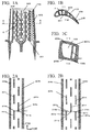
FIG. 1A is a schematic cross-sectional view showing the entire configuration of a gas turbine blade according to a first example. -
FIG. 1B is a cross-sectional view taken along line A-A ofFIG. 1A . -
FIG. 1C is an enlarged cross-sectional view showing the relevant part of the gas turbine blade which is indicated by F ofFIG. 1B . -
FIG. 2A is a configuration view showing an internal flow path of the gas turbine blade according to the first example. -
FIG. 2B is a configuration view showing an internal flow path of the gas turbine blade according to the first example. -
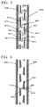
FIG. 3 is a configuration view showing a flow in an internal flow path of the gas turbine blade according to the first example. -
FIG. 4 is a configuration view showing a modified example according to the first example. -
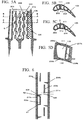
FIG. 5A is a schematic cross-sectional view showing the entire configuration of a gas turbine blade according to a second example. -
FIG. 5B is a cross-sectional view taken along line B-B ofFIG. 5A . -
FIG. 5C is a cross-sectional view taken along line C-C ofFIG. 5A . -
FIG. 5D is an enlarged cross-sectional view showing the relevant part of the gas turbine blade which is indicated by H ofFIG. 5C . -
FIG. 6 is a configuration view showing an internal flow path of the gas turbine blade according to the second example. -
FIG. 7 is a configuration view showing a flow in the internal flow path of the gas turbine blade according to the second example. -
FIG. 8A is a configuration view showing modified examples according to the first and second examples and is a cross-sectional view showing a turbine cooling blade. -
FIG. 8B is a configuration view showing a first modified example according to the first and second examples and is an enlarged cross-sectional view showing the relevant part of the turbine cooling blade which is indicated by I ofFIG. 8A . -
FIG. 8C is a configuration view showing a second modified example according to the first and second examples and is an enlarged cross-sectional view showing the relevant part of the turbine cooling blade which is indicated by I ofFIG. 8A . -
FIG. 9A is a configuration view showing an example of a structure of a conventional gas turbine blade and is a perspective view showing a gas turbine blade. -
FIG. 9B is a configuration view showing an example of a structure of a conventional gas turbine blade and is a cross-sectional view showing an internal structure of the gas turbine blade. -
FIG. 9C is a cross-sectional configuration view showing an example of a structure of a conventional gas turbine blade and is a cross-sectional view taken along line D-D ofFIG. 9B . -
FIG. 10 is a configuration view showing a flow in a conventional internal flow path. - According to one example, a cooling structure includes: a flow path provided in a blade and configured to cause a cooling medium to flow therethrough; a plurality of ribs provided in the flow path and alternately deviated and provided to be substantially parallel to a flowing direction of the cooling medium, one of the ribs being a first rib, the first rib being upstream in the flowing direction, one of the ribs being a second rib, the second rib being downstream in the flowing direction and being parallel to the first rib; and a turbulent flow generator provided between the first rib and the second rib. According to one example, a gas turbine includes a blade cooling structure. Hereinafter, examples will be described.
- Hereinafter, a configuration of a serpentine cooling medium path in a gas turbine blade according to a first example will be exemplarily described with reference to
FIGS. 1A to 3 . - Here, description of common parts of the drawings will be omitted.
- As shown in
FIG. 1A , a serpentine coolingmedium path 103 and a pin fin coolingmedium path 105, in which a plurality ofpin fins 106 are provided at a blade trailing edge, are provided in a blade. - A plurality of
ribs 201 having a predetermined length in a flow path direction are disposed in the serpentine coolingmedium path 103. - In this case, the fin-shaped
ribs 201 are alternately deviated and provided along a plurality of rows substantially parallel to a direction of theflow path 103 or a main stream of a cooling medium. - A configuration in which the ribs are disposed in two rows in a staggered pattern will be described.
-
FIG. 1B is a cross-sectional view taken along line A-A ofFIG. 1A . -
FIG. 1C is an enlarged view showing the portion indicated by F ofFIG. 1B . - Ends 207a of the
ribs 201 are provided in theflow path 103 so as to come into contact with a bladeinner wall 206a facing ablade suction side 111, and ends 208a of theribs 201 are also provided in theflow path 103 so as to come into contact with a bladeinner wall 206b facing ablade pressure side 112. - As the ribs are provided in the
flow path 103 so as to come into contact with the blade inner walls, the ribs can function as cooling fins. -
FIG. 2A is an enlarged view showing the portion indicated by E ofFIG. 1A , and an upward direction of the drawing is a downstream side. - Here, a
rib 201b (second rib) is disposed to be shifted from the position of arib 201 a (first rib) in a direction of crossing a flow path (rightward) and is disposed to be shifted downstream further than therib 201a (that is, the position of therib 201b is shifted from the position of therib 201a in the downstream direction). - As shown in
FIGS. 1A and 2A , a plurality ofribs 201 a and a plurality ofribs 201b are provided in the serpentine coolingmedium path 103. - Particularly, as a trailing
edge 210a of therib 201a is shifted downstream further than aleading edge 211a of therib 201 b, an overlappingportion 221a functioning as a turbulent flow generator is provided. The overlappingportion 221a is located between the trailingedge 210a of the first rib and theleading edge 211 a of the second rib. -
FIG. 2B shows the case in which the ribs are disposed in three rows in a staggered pattern. - Also similarly in this case, as a trailing
edge 210b of arib 201d (first rib) is shifted downstream further than aleading edge 211b of a rib 201f (second rib), an overlappingportion 221b is formed, and as a trailingedge 210c of arib 201g is shifted downstream further than aleading edge 211b of a rib 201f, an overlappingportion 221c is formed. -
FIG. 3 shows a flow of a cooling medium in a flow path when an overlapping portion is formed. - A
vortex 353 is generated at the trailing edge of each of the ribs in the flow path, and each of the ribs functions as a vortex generator. - The flow in the flow path is branched into
flows rib 201 a. - The
flow 351a is divided into aflow 351d, which is separated at a trailing edge of therib 201a passing through a region constituted by a flowpath partition wall 204a and therib 201 a, and aflow 351e, which passes through a region constituted by the flowpath partition wall 204a and therib 201 c. - A part of the
flow 351b becomes aflow 351c, and theflow 351c changes its flow direction at a leading edge of therib 201b to collide with theflow 351d to be mixed with theflow 351d in amixing region 223. - After that, the
flow 351e and aflow 351f flow downstream. - At each of the ribs, the above-mentioned flow is repeated.
- As described above, as the flow is changed into a turbulent flow by the rib, a coefficient of heat transfer is increased, heat transfer is promoted, and cooling performance is improved.
- As the overlapping
portions FIGS. 2A and 2B are provided, the mixing in the mixingregion 223 is further promoted to generate a strong turbulent flow by increasing a flow velocity while varying a direction of theflow 351 c flowing between, for example, theribs - The ribs of the example are disposed to be parallel to the direction of the flow path or the main stream of the cooling medium.
- For this reason, resistance is reduced and pressure loss is decreased in comparison to the ribs being perpendicular or slightly inclined with respect to the direction of the flow path in the conventional cooling structure.
- In addition, since the ribs are provided in the
flow path 103 so as to come into contact with the blade inner wall, the ribs also function as cooling fins. - Furthermore, since the
vortex 306a and thevortex 306b generated at upstream and downstream sides of the ribs as shown inFIG. 10 are not generated, a local decrease in a coefficient of heat transfer can be prevented, and non-uniformity of cooling performance can be prevented. - According to the above-mentioned gas turbine blade cooling structure, both of an increase in a coefficient of heat transfer and a decrease in pressure loss are achieved, and effective cooling can be performed with a small quantity of air.
- As a result, the quantity of air extracted from the compressor can be reduced and the quantity of air sent to the combustor can be increased, and thus, an effective gas turbine can be realized.
- Hereinafter, a modified example of the turbine cooling blade according to the first example will be described with reference to
FIG. 4 . - As shown in
FIG. 4 , for example, one of the side surfaces of arib 202a which faces the flowpath partition wall 204a may be parallel to the flow path or the direction of the main stream, the other of the side surfaces of therib 202a may be substantially parallel to the flow path. That is, any one of the side surfaces may be only substantially parallel to the flow path, or both side surfaces may be substantially parallel to the flow path. - Similarly, in a
rib 202b, only one side surface may be substantially parallel to the flow path or the direction of the main stream, or both of the side surfaces may be substantially parallel thereto. - Here, a trailing
edge 210d of therib 202a is preferably disposed to be downstream from aleading edge 211d of therib 202b to form an overlappingportion 222. - Hereinafter, a configuration of a serpentine cooling medium path of a turbine cooling blade according to a second example will be exemplarily described with reference to
FIGS. 5A to 7 . - As shown in
FIGS. 5A to 5D , in aserpentine flow path 103 provided in a turbine blade, fin-shapedribs 203 are provided in a plurality of rows parallel to a direction substantially parallel to a flow path in the blade or a direction of a main stream in a staggered pattern. - Furthermore, a
protrusion 205 serving as a turbulent flow generator is provided downstream from each of theribs 203. Theprotrusion 205 is provided so as to protrude from an inner wall surface of the flow path. - A configuration in which the rigs are disposed in two rows in a staggered pattern will be exemplarily described.
-
FIG. 5C is a cross-sectional view taken along line C-C ofFIG. 5A . - As shown in
FIG. 5D serving as an enlarged view showing the portion indicated by H ofFIG. 5C , ends 207b (upper end) of theribs 203 are provided in theflow path 103 so as to come into contact with a bladeinner wall 206a opposing theblade suction side 111, and ends 208b (lower end) of theribs 203 are provided in theflow path 103 so as to come into contact with the bladeinner wall 206b opposing theblade pressure side 112. - As shown in
FIG. 5B serving as a cross-sectional view taken along line B-B ofFIG. 5A , theprotrusions 205 are also provided in theflow path 103 so as to come into contact with the blade inner wall. Particularly, the upper ends of theprotrusions 205 are provided in theflow path 103 so as to come into contact with a bladeinner wall 206a opposing theblade suction side 111, and the lower ends of theprotrusions 205 are provided in theflow path 103 so as to come into contact with the bladeinner wall 206b opposing theblade pressure side 112. - As the ribs and the protrusions are provided in the
flow path 103 so as to come into contact with the blade inner wall, the ribs and the protrusions can function as cooling fins. - In the ribs, as shown in
FIG. 6 serving as an enlarged view showing the portion indicated by G ofFIG. 5A , arib 203a is disposed such that a cross-sectional area of a region constituted by the flowpath partition wall 204a and therib 203a is S1, and theprotrusion 205 is disposed such that a cross-sectional area between a trailingedge 210e of therib 203a and theprotrusion 205 is S2. - Here, the flow path cross-sectional areas are preferably S1 > S2.
- It is preferable that a
rib 203b (second rib) located downstream from therib 203a (first rib) be disposed such that agap 225 is provided between theprotrusion 205 and therib 203b. - As shown in
FIG. 7 , aflow 352a branched off intoflows path partition wall 204a and therib 203a and are accelerated by theprotrusion 205 to be guided to the vicinity of a center of the flow path by therib 203a in the flow path. - The
flow 352b and theflow 352a collide with each other to be mixed in amixing region 224. - After that, the flow is branched off into a
flow 352c and aflow 352d to flow downstream. - The above-mentioned flow is repeated by each of the ribs and each of the protrusions.
- As described above, as the flow is changed into a turbulent flow by the ribs and the protrusions, a coefficient of heat transfer is increased, heat transfer is promoted, and cooling performance is improved.
- As shown in
FIG. 6 , theprotrusion 205 is preferably located upstream from aleading edge 211e of therib 203b of the downstream side to form thegap 225. That is, thegap 225 is provided between theleading edge 211e of therib 203b and theprotrusion 205. - In addition, the flow path cross-sectional areas S1 and S2 are preferably S1 > S2.
- According to S1 > S2, the
flow 352a is accelerated when theflow 352a passes through the protrusion, a better mixing effect is obtained, and cooling performance is improved. - Since the ribs of the example are disposed to be substantially parallel to a direction of the flow path or a main stream of a cooling medium, a resistance is decreased and pressure loss is reduced in comparison to the ribs being perpendicular or slightly inclined with respect to the direction of the flow path in the conventional cooling structure.
- In addition, since the ribs and the protrusions are provided in the
flow path 103 so as to come into contact with the blade inner wall, the ribs and the protrusions can also function as cooling fins. - Furthermore, since the
vortices FIG. 10 are not generated, a local decrease in a coefficient of heat transfer can be prevented, heat transfer is promoted, and non-uniformity of cooling performance can be prevented. - According to the above-mentioned gas turbine blade cooling structure, both of an increase in a coefficient of heat transfer and a decrease in pressure loss are achieved, and effective cooling can be performed with a small quantity of air.
- As a result, a quantity of air extracted from the compressor can be reduced, and a quantity of air sent to the combustor can be increased.
- Hereinafter, modified examples of the turbine cooling blade according to the first and second examples will be described with reference to
FIGS. 8A to 8C . - As shown in
FIG. 8B serving as an enlarged view showing the portion indicated by I ofFIG. 8A , anend 207a (upper end) of arib 209a may not come into contact with the bladeinner wall 206a to form agap 226a, and theend 208a (lower end) may be provided in theflow path 103 so as to come into contact with the bladeinner wall 206b. - In this case, an upper end of a protrusion may not come into contact with the blade
inner wall 206a to form agap 226a, and a lower end of the protrusion may be provided in theflow path 103 so as to come into contact with the bladeinner wall 206b. - Similarly, as shown in
FIG. 8C , anend 207b (upper end) of arib 209b may be provided in theflow path 103 so as to come into contact with the bladeinner wall 206a, and theend 208b (lower end) may not come into contact with the bladeinner wall 206b to form agap 226b. - In this case, an upper end of a protrusion may be provided in the
flow path 103 so as to come into contact with the bladeinner wall 206a, and a lower end of the protrusion may not come into contact with the bladeinner wall 206b to form agap 226b. - As shown in
FIGS. 8B and 8C , even when only one of the ends of each of the ribs comes into contact with the blade inner wall, the same effect can be obtained as when both of the ends come into contact with the blade inner wall. - Furthermore, when only one of the ends of each of the ribs come into contact with the blade inner wall, flows in the
gap 226a between therib 209a and the bladeinner wall 206a and thegap 226b between therib 209b and the bladeinner wall 206b are accelerated. - As a result, a better mixing effect is obtained, heat transfer is promoted, and cooling performance is improved.
- As the gas turbine cooling blade having the above-mentioned configuration is provided, an increase in pressure loss caused by an increase in resistance due to the ribs in a conventional structure and non-uniformity of cooling performance caused by the generation of vortices of the upstream and downstream sides of the ribs can be prevented.
- Accordingly, both of an increase in a coefficient of heat transfer and a decrease in pressure loss are achieved, and the turbine blade can be effectively cooled with a small quantity of air.
- As a result, a decrease in thermal efficiency of the gas turbine caused by an increase in an amount of cooling air can be prevented, and performance of the gas turbine can be improved.
- In this specification, while the plurality of arrangements have been described, these arrangements are merely exemplarily provided but not are intended to limit the scope of the claims.
- Specifically, both or any one of the first and second examples may be combined.
- While certain arrangements have been described, these arrangements have been presented by way of example only, and are not intended to limit the scope of the claims. Indeed, the apparatuses described herein may be embodied in a variety of other forms; furthermore various omissions, substitutions and changes in the form of the apparatuses described herein may be made.
Claims (9)
- A cooling structure comprising:a flow path (103) provided in a blade and configured to cause a cooling medium to flow therethrough;a plurality of ribs (201) provided in the flow path (103) and alternately deviated and provided to be substantially parallel to a flowing direction of the cooling medium, one of the ribs (201) being a first rib (201a, 201d), the first rib (201 a, 201 d) being upstream in the flowing direction, one of the ribs (201) being a second rib (201b, 201f), the second rib (201b, 201f) being downstream in the flowing direction and being parallel to the first rib (201 a, 201 d); anda turbulent flow generator (221 a, 205) provided between the first rib (201 a, 201d) and the second rib (201b, 201f).
- The cooling structure according to claim 1, wherein the turbulent flow generator (221 a, 205) is an overlapping portion (221a) between a rear end of the first rib (201a, 201d) and a front end of the second rib (201b, 201f).
- The cooling structure according to claim 1, wherein the turbulent flow generator (221a, 205) is a protrusion (205) protruding from an inner wall surface of the flow path (103).
- The cooling structure according to claim 3, wherein the protrusion (205) is located upstream from a leading edge (211 a) of the second rib (201b, 201f) to provide a gap (225, 226a, 226b).
- The cooling structure according to claim 3 or 4, wherein a flow path cross-sectional area (S1) between the first rib (201 a, 201 d) and an inner wall surface of the flow path (103) is larger than a flow path cross-sectional area (S2) between a trailing edge (210e) of the first rib (201a, 201d) and the protrusion (205).
- The cooling structure according to any one of claims 1 to 5, wherein each rib has an upper end and a lower end, the turbulent flow generator (221 a, 205) is a protrusion (205) that has an upper end and a lower end, and upper ends of the rib and the protrusion (205) and lower ends of the rib and the protrusion (205) are provided so as to come into contact with a flow path wall surface opposite to a back surface and a ventral surface of the blade.
- The cooling structure according to any one of claims 1 to 5, wherein, each rib has an upper end and a lower end, the turbulent flow generator (221a, 205) is a protrusion (205) that has an upper end and a lower end, one set of upper ends and lower ends of the rib and the protrusion (205) comes into contact with the flow path wall surface, and the other set of the upper ends and the lower ends does not come into contact with the flow path wall surface to form a gap (225, 226a, 226b).
- A gas turbine comprising the cooling structure according to any one of claims 1 to 7.
- A cooling structure comprising:a flow path (103) provided in a blade and configured to cause a cooling medium to flow therethrough;a plurality of ribs (201) provided in the flow path (103) and alternately deviated and provided to be substantially parallel to a flowing direction of the cooling medium, one of the ribs (201) being a first rib (201a, 201 d), the first rib (201a, 201d) being upstream in the flowing direction, one of the ribs (201) being a second rib (201b, 201f), the second rib (201b, 201f) being downstream in the flowing direction and being parallel to the first rib (201a, 201 d); andan overlapping portion (221 a) provided between a rear end of the first rib (201a, 201d) and a front end of the second rib (201b, 201f), the overlapping portion (221 a) being configured to generate a turbulent flow in flow of the cooling medium.
Applications Claiming Priority (1)
| Application Number | Priority Date | Filing Date | Title |
|---|---|---|---|
| JP2015225095A JP2017089601A (en) | 2015-11-17 | 2015-11-17 | Cooling structure and gas turbine |
Publications (1)
| Publication Number | Publication Date |
|---|---|
| EP3170975A1 true EP3170975A1 (en) | 2017-05-24 |
Family
ID=56888992
Family Applications (1)
| Application Number | Title | Priority Date | Filing Date |
|---|---|---|---|
| EP16187785.7A Withdrawn EP3170975A1 (en) | 2015-11-17 | 2016-09-08 | Cooling structure and gas turbine |
Country Status (3)
| Country | Link |
|---|---|
| US (1) | US20170138204A1 (en) |
| EP (1) | EP3170975A1 (en) |
| JP (1) | JP2017089601A (en) |
Cited By (1)
| Publication number | Priority date | Publication date | Assignee | Title |
|---|---|---|---|---|
| CN115126548A (en) * | 2022-07-29 | 2022-09-30 | 中国联合重型燃气轮机技术有限公司 | Turbine blade with airflow channel turbulent flow structure and gas turbine |
Families Citing this family (4)
| Publication number | Priority date | Publication date | Assignee | Title |
|---|---|---|---|---|
| US10156157B2 (en) * | 2015-02-13 | 2018-12-18 | United Technologies Corporation | S-shaped trip strips in internally cooled components |
| US10830060B2 (en) * | 2016-12-02 | 2020-11-10 | General Electric Company | Engine component with flow enhancer |
| US10907480B2 (en) | 2018-09-28 | 2021-02-02 | Raytheon Technologies Corporation | Ribbed pin fins |
| US11015455B2 (en) * | 2019-04-10 | 2021-05-25 | Pratt & Whitney Canada Corp. | Internally cooled turbine blade with creep reducing divider wall |
Citations (6)
| Publication number | Priority date | Publication date | Assignee | Title |
|---|---|---|---|---|
| FR1374159A (en) * | 1962-12-05 | 1964-10-02 | Gen Motors Corp | Turbine blade |
| US5468125A (en) * | 1994-12-20 | 1995-11-21 | Alliedsignal Inc. | Turbine blade with improved heat transfer surface |
| US20060153679A1 (en) * | 2005-01-07 | 2006-07-13 | Siemens Westinghouse Power Corporation | Cooling system including mini channels within a turbine blade of a turbine engine |
| US20120207591A1 (en) * | 2011-02-15 | 2012-08-16 | Ching-Pang Lee | Cooling system having reduced mass pin fins for components in a gas turbine engine |
| WO2015073092A2 (en) * | 2013-09-05 | 2015-05-21 | United Technologies Corporation | Gas turbine engine airfoil turbulator for airfoil creep resistance |
| US20150198050A1 (en) * | 2014-01-15 | 2015-07-16 | Siemens Energy, Inc. | Internal cooling system with corrugated insert forming nearwall cooling channels for airfoil usable in a gas turbine engine |
-
2015
- 2015-11-17 JP JP2015225095A patent/JP2017089601A/en active Pending
-
2016
- 2016-09-08 EP EP16187785.7A patent/EP3170975A1/en not_active Withdrawn
- 2016-09-08 US US15/259,762 patent/US20170138204A1/en not_active Abandoned
Patent Citations (6)
| Publication number | Priority date | Publication date | Assignee | Title |
|---|---|---|---|---|
| FR1374159A (en) * | 1962-12-05 | 1964-10-02 | Gen Motors Corp | Turbine blade |
| US5468125A (en) * | 1994-12-20 | 1995-11-21 | Alliedsignal Inc. | Turbine blade with improved heat transfer surface |
| US20060153679A1 (en) * | 2005-01-07 | 2006-07-13 | Siemens Westinghouse Power Corporation | Cooling system including mini channels within a turbine blade of a turbine engine |
| US20120207591A1 (en) * | 2011-02-15 | 2012-08-16 | Ching-Pang Lee | Cooling system having reduced mass pin fins for components in a gas turbine engine |
| WO2015073092A2 (en) * | 2013-09-05 | 2015-05-21 | United Technologies Corporation | Gas turbine engine airfoil turbulator for airfoil creep resistance |
| US20150198050A1 (en) * | 2014-01-15 | 2015-07-16 | Siemens Energy, Inc. | Internal cooling system with corrugated insert forming nearwall cooling channels for airfoil usable in a gas turbine engine |
Cited By (1)
| Publication number | Priority date | Publication date | Assignee | Title |
|---|---|---|---|---|
| CN115126548A (en) * | 2022-07-29 | 2022-09-30 | 中国联合重型燃气轮机技术有限公司 | Turbine blade with airflow channel turbulent flow structure and gas turbine |
Also Published As
| Publication number | Publication date |
|---|---|
| US20170138204A1 (en) | 2017-05-18 |
| JP2017089601A (en) | 2017-05-25 |
Similar Documents
| Publication | Publication Date | Title |
|---|---|---|
| US7637720B1 (en) | Turbulator for a turbine airfoil cooling passage | |
| US8168912B1 (en) | Electrode for shaped film cooling hole | |
| US8221055B1 (en) | Turbine stator vane with endwall cooling | |
| CN107429568B (en) | Internal cooling system with converging-diverging outlet slots in trailing-edge cooling passages for airfoils in turbine engines | |
| US8920111B2 (en) | Airfoil incorporating tapered cooling structures defining cooling passageways | |
| US8066485B1 (en) | Turbine blade with tip section cooling | |
| US20150198050A1 (en) | Internal cooling system with corrugated insert forming nearwall cooling channels for airfoil usable in a gas turbine engine | |
| US8167559B2 (en) | Turbine vane for a gas turbine engine having serpentine cooling channels within the outer wall | |
| US9863256B2 (en) | Internal cooling system with insert forming nearwall cooling channels in an aft cooling cavity of an airfoil usable in a gas turbine engine | |
| US8944763B2 (en) | Turbine blade cooling system with bifurcated mid-chord cooling chamber | |
| CA2497755A1 (en) | Microcircuit cooling for a turbine airfoil | |
| US8721281B2 (en) | Cooled blade for a gas turbine | |
| US20180045059A1 (en) | Internal cooling system with insert forming nearwall cooling channels in an aft cooling cavity of a gas turbine airfoil including heat dissipating ribs | |
| US20170138204A1 (en) | Cooling structure and gas turbine | |
| US20090068023A1 (en) | Multi-pass cooling for turbine airfoils | |
| JP2003232204A (en) | Crossover-cooled airfoil trailing edge | |
| JP2007255425A (en) | Passage for flowing fluid and part having the passage | |
| US9903209B2 (en) | Rotor blade and guide vane airfoil for a gas turbine engine | |
| CN107131006B (en) | Turbine blade | |
| US20150152738A1 (en) | Turbine airfoil cooling passage with diamond turbulator | |
| JP2002129903A (en) | Structure of cooling gas turbine blade | |
| CN110337530A (en) | The cooling structure of turbo blade | |
| TWI710696B (en) | Turbine blades and gas turbines | |
| CN112343666A (en) | A corrugated rib diversion structure applied to half-split slits at the trailing edge of turbine blades | |
| CN110392769A (en) | The cooling structure of turbo blade |
Legal Events
| Date | Code | Title | Description |
|---|---|---|---|
| PUAI | Public reference made under article 153(3) epc to a published international application that has entered the european phase |
Free format text: ORIGINAL CODE: 0009012 |
|
| 17P | Request for examination filed |
Effective date: 20160908 |
|
| AK | Designated contracting states |
Kind code of ref document: A1 Designated state(s): AL AT BE BG CH CY CZ DE DK EE ES FI FR GB GR HR HU IE IS IT LI LT LU LV MC MK MT NL NO PL PT RO RS SE SI SK SM TR |
|
| AX | Request for extension of the european patent |
Extension state: BA ME |
|
| 17Q | First examination report despatched |
Effective date: 20180605 |
|
| STAA | Information on the status of an ep patent application or granted ep patent |
Free format text: STATUS: THE APPLICATION HAS BEEN WITHDRAWN |
|
| 18W | Application withdrawn |
Effective date: 20180813 |