EP3170796A1 - Biocidal purification device - Google Patents
Biocidal purification device Download PDFInfo
- Publication number
- EP3170796A1 EP3170796A1 EP16202186.9A EP16202186A EP3170796A1 EP 3170796 A1 EP3170796 A1 EP 3170796A1 EP 16202186 A EP16202186 A EP 16202186A EP 3170796 A1 EP3170796 A1 EP 3170796A1
- Authority
- EP
- European Patent Office
- Prior art keywords
- cap
- led
- spout
- container
- opening
- Prior art date
- Legal status (The legal status is an assumption and is not a legal conclusion. Google has not performed a legal analysis and makes no representation as to the accuracy of the status listed.)
- Granted
Links
Images


Classifications
-
- C—CHEMISTRY; METALLURGY
- C02—TREATMENT OF WATER, WASTE WATER, SEWAGE, OR SLUDGE
- C02F—TREATMENT OF WATER, WASTE WATER, SEWAGE, OR SLUDGE
- C02F1/00—Treatment of water, waste water, or sewage
- C02F1/30—Treatment of water, waste water, or sewage by irradiation
- C02F1/32—Treatment of water, waste water, or sewage by irradiation with ultraviolet light
- C02F1/325—Irradiation devices or lamp constructions
-
- C—CHEMISTRY; METALLURGY
- C02—TREATMENT OF WATER, WASTE WATER, SEWAGE, OR SLUDGE
- C02F—TREATMENT OF WATER, WASTE WATER, SEWAGE, OR SLUDGE
- C02F2103/00—Nature of the water, waste water, sewage or sludge to be treated
- C02F2103/02—Non-contaminated water, e.g. for industrial water supply
- C02F2103/026—Treating water for medical or cosmetic purposes
-
- C—CHEMISTRY; METALLURGY
- C02—TREATMENT OF WATER, WASTE WATER, SEWAGE, OR SLUDGE
- C02F—TREATMENT OF WATER, WASTE WATER, SEWAGE, OR SLUDGE
- C02F2201/00—Apparatus for treatment of water, waste water or sewage
- C02F2201/32—Details relating to UV-irradiation devices
- C02F2201/322—Lamp arrangement
- C02F2201/3221—Lamps suspended above a water surface or pipe
-
- C—CHEMISTRY; METALLURGY
- C02—TREATMENT OF WATER, WASTE WATER, SEWAGE, OR SLUDGE
- C02F—TREATMENT OF WATER, WASTE WATER, SEWAGE, OR SLUDGE
- C02F2201/00—Apparatus for treatment of water, waste water or sewage
- C02F2201/32—Details relating to UV-irradiation devices
- C02F2201/322—Lamp arrangement
- C02F2201/3222—Units using UV-light emitting diodes [LED]
-
- C—CHEMISTRY; METALLURGY
- C02—TREATMENT OF WATER, WASTE WATER, SEWAGE, OR SLUDGE
- C02F—TREATMENT OF WATER, WASTE WATER, SEWAGE, OR SLUDGE
- C02F2201/00—Apparatus for treatment of water, waste water or sewage
- C02F2201/32—Details relating to UV-irradiation devices
- C02F2201/322—Lamp arrangement
- C02F2201/3228—Units having reflectors, e.g. coatings, baffles, plates, mirrors
-
- C—CHEMISTRY; METALLURGY
- C02—TREATMENT OF WATER, WASTE WATER, SEWAGE, OR SLUDGE
- C02F—TREATMENT OF WATER, WASTE WATER, SEWAGE, OR SLUDGE
- C02F2201/00—Apparatus for treatment of water, waste water or sewage
- C02F2201/32—Details relating to UV-irradiation devices
- C02F2201/326—Lamp control systems
-
- C—CHEMISTRY; METALLURGY
- C02—TREATMENT OF WATER, WASTE WATER, SEWAGE, OR SLUDGE
- C02F—TREATMENT OF WATER, WASTE WATER, SEWAGE, OR SLUDGE
- C02F2209/00—Controlling or monitoring parameters in water treatment
- C02F2209/005—Processes using a programmable logic controller [PLC]
-
- C—CHEMISTRY; METALLURGY
- C02—TREATMENT OF WATER, WASTE WATER, SEWAGE, OR SLUDGE
- C02F—TREATMENT OF WATER, WASTE WATER, SEWAGE, OR SLUDGE
- C02F2303/00—Specific treatment goals
- C02F2303/04—Disinfection
-
- C—CHEMISTRY; METALLURGY
- C02—TREATMENT OF WATER, WASTE WATER, SEWAGE, OR SLUDGE
- C02F—TREATMENT OF WATER, WASTE WATER, SEWAGE, OR SLUDGE
- C02F2307/00—Location of water treatment or water treatment device
- C02F2307/02—Location of water treatment or water treatment device as part of a bottle
Definitions
- the present invention relates to a biocidal fluid purification cap for a fluid container, preferably for a container intended to store purified water for the use in laboratory environments, i.e. water for cell culture or water for use in molecular biology, biochemistry or microbiology applications, but also purified water for use in the medical or health care field in general.
- the invention in this context specifically relates to static biocidal or bactericidal laboratory water purification devices based on a UV-LED light source.
- Bottled or packaged purified water is subject to strict quality control tests and is delivered with a certificate of quality.
- the two types of water for example water for cell culture and water for molecular biology, are intended for research use by scientists performing critical cell culture and molecular biology experiments. Both water types are sterile. Additionally, water for cell culture is cell-culture tested and free of pyrogens, mycoplasma, calcium and magnesium. Water for molecular biology is RT-PCR tested and is RNase-free, DNase-free, protease-free, calcium-free and magnesium-free. Following a purification process, the purified water is aseptically filled into sterile containers, e.g. PET-containers. These relatively small reservoirs or bottles, normally with a volume of less than 1 liter, are transported to the point of use in the laboratory experiments.
- LED light sources have been proposed.
- a hand-held ultraviolet water purification system which includes an outwardly-extending pen-light sized configuration of solid state UV-light emitting diodes that emit ultraviolet light in the germicidal range.
- the system may include a battery and a timing circuit for operating the diodes.
- WO 2010/104096 A1 discloses another water purifier which comprises a water container with a spout and a water purifying part including an ultraviolet light-emitting diode located within the container so as to irradiate the ultraviolet light generated by the diode within a water passage of the container.
- This device too, is disadvantageous in that the water-purifying part is completely immersed into the water within the container.
- the present invention provides a biocidal fluid purification cap for a fluid container as defined in claim 1. Preferred embodiments are defined in the dependent claims.
- the biocidal fluid purification cap for a fluid container comprises a cap body including an engagement feature for removably attaching the cap body to a mating engagement feature on a spout of the fluid container to hermetically close a spout opening, at least one LED adapted to emit light in the UV-C range, electronic circuitry for driving the LED(s), and a power supply for the electronic circuitry, wherein said LED(s) is/are arranged in said cap body so as to be separated from the environment by an UV-transparent window provided in the cap body such that light emitted from said LED(s) enters the opening of the spout when the cap is attached to the spout of the container.
- the purification cap of the invention is particularly advantageous in that it can be attached to and used in combination with common fluid containers used in the industry, for example, bottles, flasks, or bags, either rigid or semi-rigid, preferably with a volume of less than 2 liters for purified water serving as laboratory supply for cell culture and molecular biology, without requiring modification of the existing containers.
- the cap body includes the engagement feature for removably attaching the cap body to a mating engagement feature on the spout of such a fluid container.
- the one or more LED(s) is/are integrated into the cap body so as to be separated from the environment, which is typically the interior volume of the container when in use, by a UV-transparent window.
- the UV-transparent window shields the LED(s) and the circuitry for driving the LED(s) and integrating other control functions from water ingress so as to reduce potential contamination and damage and facilitate sterilization of the device.
- the window and arrangement of the LED(s) also shields the heat from the water, thereby reducing the risk of promoting the microorganism growth, including bacteria, virus and mycoplasma, during the use once the container closed by the cap has been opened.
- the device of the invention corresponds to a cap in design and use, it is extremely easy to manipulate and handle.
- the biocidal fluid purification cap of the present invention has a cap body 3, formed in this example, from a lower part 4 and an upper part 5 accomodating the functional elements including the LED(s) and those for driving the LED(s) as well as supporting elements there between so that these elements are sealed from the environment.
- the lower part 4 of the cap body 3 includes an engagement feature 20 (see Fig. 2 ) for removably attaching the cap body to a mating engagement feature on an outer peripheral portion of a spout of a fluid container to hermetically close a spout opening.
- the engagement feature 20 may include a threaded/screw type or bayonet type of engagement structure or an elastic insertion engagement by frictional or form-locking engagement, for example in the form of a tight rubber or plastic seal arrangement.
- the engagement feature is preferably one of the common types or standard threads used in connection with the containers that are normally used for holding purified water serving as laboratory supply for cell culture or molecular biology.
- the container for this type of use preferably has a volume of less than 2 liters and is formed of PET, glass or plastics material including an UV resistant additive agent, in the form of a bottle, a flask or a bag, which can be rigid or semi-rigid or flexible overall except for the spout portion.
- the upper part of the cap body 3 and especially the upper part 5 but also the lower part 4 may include serrations or other forms of friction enhancing surface features 5a at external portions improving the grip of a user on the cap.
- Such a feature is schematically shown by the ribbed or knurled portion 5a in Fig. 3 .
- This grip-portion may of course extend to other parts of the outer surface of the cap and the entire configuration of the cap is not restricted to the configuration shown in these figures.
- At least one LED 7a adapted to emit light in the UV-C range, i.e. preferably in a light range in the wavelength of 220 nm - 300 nm, preferably of 260 nm +/- 5 nm.
- the light emitting layers of a suitable LED type are epitaxial crystal growth of AIGaN on different wafer substrates, for example.
- the power of the LED(s) will be selected based on the desired intensity of the UV-light in the stated range which will normally depend on the size and volume of the fluid container with which the cap is to be used.
- Suitable UV LEDs are commercially available, e.g. from Seoul Optodevice, reference number CUD8AF1 A.
- a plurality of LEDs are integrated on a printed circuit board (PCB) 7 to produce the desired power and to allow dimming or modulating of the power as well as a certain redundancy in case of failure of individual LED(s) as will be described further below.
- PCB printed circuit board
- the PCB 7 is preferably made with a metal base and is arranged in the cap body 3 so as to allow heat dissipation to the environment to the side that is remote or facing away from the side facing the interior of the container.
- the heat produced by the LED(s) can be more easily guided to the upper part of the cap body 3 and dissipated to the environment without substantial influence on the water in the container.
- the friction enhancing feature 5a in the form of ribs etc. may additionally serve to increase the surface area to improve heat dissipation to the environment.
- the cap also includes the necessary electronic circuitry 15 for driving the LED(s) and a power supply for the electronic circuitry.
- power supply may include single-use or rechargeable batteries (not shown) received in the cap body and/or a connector and/or a contact-less transmitting means to an external power source (not shown).
- the connector is preferably in the form of a USB-socket or plug in accordance with standard charging equipment that is also used in connection with PC-peripherals or mobile telephones.
- the electronic circuitry also may include a function for charging the battery by external power supplied through the connector or contact-less through induction.
- the PCB 7 supporting the LED(s) 7a is mounted to the lower part of the cap body 4 by way of a holding bracket 8 that is attached by a number of screws 8a to bosses 8b protruding from the lower part 4 of the cap body 3.
- a sealing ring 12 and a UV-transparent window 6 is interposed between the receptacle in the lower part of the cap body 4 and the bracket 8.
- the UV-transparent window separates the LED(s) from the environment such that light emitted from the LED(s) may pass through the window 6 and enter the opening of the spout when the cap is attached to the spout of the container.
- the window is thus located above the engagement feature 20 as shown in Fig. 2 .
- the sealing ring 12 is optionally provided to guarantee that no liquid may enter beyond the UV-transparent window.
- the UV-transparent window is made from quartz or silica glass, for example.
- the space between the lower and upper parts of the cap body may further receive a switch 13 (see Figs. 2 and 3 ) that is arranged so that it can detect removal of the cap from the spout of the container and can deactivate the operation of the LED(s) via suitable circuitry in response.
- This feature can protect the user from direct exposure to the UV-light of the LED(s) irradiated through the UV-transparent window when the cap is removed from the container and increases the lifetime of the batteries.
- the removal may be detected via the switch through a mechanical contact, i.e. in the form of a micro-switch lever, or contact-less by a suitable sensor replacing the mechanical switch.
- the electronic circuitry 15 integrated into the cap may also include an interface and a function for receiving control signals from a remote device to program function settings of the circuitry and/or to read out or read-in operational parameters or other data. This exchange of control signals can be through a cable, the connector for the external power source and/or contactless through known technical means for contactless data exchange.
- the electronic circuitry 15 in the cap may also include a function for modulating the drive power supplied to the LED(s) to allow dimming and/or intermittent operation of the LED(s) according to a predefined time and/or intensity schedule. The dimmed and/or intermittent operation is a means for managing the thermal dissipation of the LED(s) to avoid warming of the water in the container and may of course prolong the life-time of the battery.
- the scheduled timing may be switched on at100% of its power until the batteries are empty or may allow a pulsed operation of all or selected ones of the LED(s) for short increments of time or a continuous irradiation at a reduced power level.
- the desired irradiation pattern can be selected through a further switch integrated into the cap body and accessible to the outside or may be programmed through the above- described data interface.
- An LED dimming function may be implemented, for example, by pulse width modulation of the power signal to the LED(s) which has a variable duty cycle in order to decrease the average intensity of the UV irradiation.
- a 10% duty cycle (10ms on and 90ms off) may maintain a constant minimal level of UV light energy blocking microorganism regrowth while not affecting dramatically the lifetime of the power supply.
- a heat sensor or thermistor may be integrated in the circuitry to detect the temperature of the LED(s) and trigger a dimming function to extend the lifetime of the LED(s) that would be impaired by excessive heat and/or reduce the risk of microorganism growth and vapor deposition on the internal walls of the container.
- the various functions of the circuitry can be integrated all on the PCB supporting the LED(s) or may be located at different modular PCBs received at various spaces within the cap body.
- An exemplary separate PCB bearing certain electronic circuitry is shown in Fig. 3 and is identified by the reference numeral 11.
- a general power or function switch 10 may be also integrated and accessible to the outside of the cap body.
- An example of the various circuit functions that might be integrated into the cap is shown in Fig. 6 .
- the control circuitry is summarized as "LED control module" and the external elements are shown as functional elements communicating therewith.
- the cap body may include additional parts or covers that can be selectively removed, for example, to exchange batteries.
- additional removable part is schematically represented by the lid 9 in Fig. 3 that is removably attached to the top side of the upper part of the cap body.
- the lid 9 may also be transparent to receive information or handling instructions regarding the use of the cap or the content of the container. It may also allow hand-written indications on it regarding the date and time of the first opening, etc. or may incorporate a display (i.e. a small LCD) or other indicators communicating with the LED control module.
- a display i.e. a small LCD
- the cap body 3 may be partially or completely made from a material that reflects UV-rays, for example, aluminum or PTFE or stainless steel, preferably at those portions upstream or downstream of the UV-transparent window 6 that are exposed to the light irradiation from the LED(s) 7a.
- a material that reflects UV-rays for example, aluminum or PTFE or stainless steel, preferably at those portions upstream or downstream of the UV-transparent window 6 that are exposed to the light irradiation from the LED(s) 7a.
- Such UV-ray reflective structures 14 are schematically shown in Fig. 4 and they are arranged to direct the rays towards the spout opening.
- the material may be coated or covered with an oxidizing preventing layer of a UV-transparent material such as silica or quartz.
- the UV-reflecting material may also be applied in the form of a coating on other supporting material and restricted to those parts that are actually exposed to UV-radiation during use.
- an additional light source in the visible range for example, an LED irradiating light in the visible range, may be integrated on the PCB such that its light is at least partially visible from outside.
- a cap body 3 includes a fluid opening 16 communicating with or accessible to the outside of the cap body and a fluid opening 17 communicating with the spout opening of the container when the cap is attached to the spout as well as a fluid channel 18 extending between these fluid openings 16, 17 and passing between the UV-transparent window 6 and a further UV- transparent window 9 facing the opening of the spout to allow, in operation, the light emitted from the LED(s) to pass through the first UV- transparent window 6 and then through the fluid channel 18, before passing the second UV-transparent window 19 and entering the spout opening of the container.
- This modification allows introduction and/or extraction of fluid into/out from the container while the cap remains arranged on the spout, for example by way of a syringe or an inlet tubing coupled with the fluid opening 16.
- a seal or syringe connection including a check valve may be provided at the opening 16 to maintain the sterility of the interior of the container.
- An additional (not shown) vent filter may be included into the cap body if larger amounts of fluid are to be filled into the container through such a fluid channel.
- the structure may also be used to extract fluid from the container without removing the purification cap, for example by turning the container upside down in a position with the cap facing downward and extracting the fluid through a syringe coupled to the fluid opening 16 or valve.
- a suitable further seal arrangement may be provided at the fluid opening 17 to maintain the sterility of the interior of the cap and container.
- the biocidal fluid purification cap for a fluid container of the invention provides a number of advantages which includes the possibility to irradiate small water volumes in standard containers and maintain their sterility over considerable time periods even after the container has been opened once.
- the wavelength of the UV-LED(s) is narrow and deep enough to be completely blocked by most plastics materials used for forming the containers.
- the integration of the LED(s) into the top portion of the cap allows secure heat dissipation to the environment involving warming of the water and microorganism growth promotion in the container. It also expands the lifetime of the LED(s). This aspect may be further improved by the dimming functions integrated into the circuitry of the purification cap for driving the LED(s).
- the power consumption of the common LED(s) in the wavelength is much lower than mercury-based solutions allowing for power consumption savings and extension of the use time. As compared to mercury-based purification concepts, there is less degradation of plastic from the tank and leaching of organic into the water and no risk of hazardous contamination.
Landscapes
- Health & Medical Sciences (AREA)
- Toxicology (AREA)
- Life Sciences & Earth Sciences (AREA)
- Hydrology & Water Resources (AREA)
- Engineering & Computer Science (AREA)
- Environmental & Geological Engineering (AREA)
- Water Supply & Treatment (AREA)
- Chemical & Material Sciences (AREA)
- Organic Chemistry (AREA)
- Apparatus For Disinfection Or Sterilisation (AREA)
- Physical Water Treatments (AREA)
- Closures For Containers (AREA)
Abstract
Description
- The present invention relates to a biocidal fluid purification cap for a fluid container, preferably for a container intended to store purified water for the use in laboratory environments, i.e. water for cell culture or water for use in molecular biology, biochemistry or microbiology applications, but also purified water for use in the medical or health care field in general. The invention in this context specifically relates to static biocidal or bactericidal laboratory water purification devices based on a UV-LED light source.
- Bottled or packaged purified water is subject to strict quality control tests and is delivered with a certificate of quality. The two types of water, for example water for cell culture and water for molecular biology, are intended for research use by scientists performing critical cell culture and molecular biology experiments. Both water types are sterile. Additionally, water for cell culture is cell-culture tested and free of pyrogens, mycoplasma, calcium and magnesium. Water for molecular biology is RT-PCR tested and is RNase-free, DNase-free, protease-free, calcium-free and magnesium-free. Following a purification process, the purified water is aseptically filled into sterile containers, e.g. PET-containers. These relatively small reservoirs or bottles, normally with a volume of less than 1 liter, are transported to the point of use in the laboratory experiments.
- If the purified water is stored for longer periods of time or if only small amounts of water are taken out of a container, there is a risk of contamination of the remaining water because the water does not contain any chlorine or chemical sanitization agents. To solve this problem at present various counter measures are used. One is the disposing of once- opened bottles including all the unused water. Another is the freezing of once-opened bottles in a refrigerator. Further solutions are the use of mercury-based vapor lamps installed in a reservoir or inserted into a reservoir from the outside or the use of a recirculation pump through a mercury-based lamp reactor before the water is used.
- The prior art devices using lamps containing mercury require a specific recycling procedure and extreme care and attention because mercury is a toxic element. Mercury pollution released into the environment is a serious threat. A particular risk exists if a lamp breaks during maintenance or operation. The manipulation of existing mercury lamps therefore involves additional safety constraints and measures. In addition, the existing mercury lamps produce considerable heat which will increase the water temperature. The higher water temperature is promoting microorganism growth and cause condensation of water vapor on the container wall which produces static droplets on the cooler areas of the container which are favoring biofilm development.
- To solve part of the problems LED light sources have been proposed. One example is disclosed in
US 6579495 B1 in the form of a hand-held ultraviolet water purification system which includes an outwardly-extending pen-light sized configuration of solid state UV-light emitting diodes that emit ultraviolet light in the germicidal range. The system may include a battery and a timing circuit for operating the diodes. The application of the system due to its intended contact by immersion into the water imposes the risk of unintended contamination or complicated handling. -
WO 2010/104096 A1 discloses another water purifier which comprises a water container with a spout and a water purifying part including an ultraviolet light-emitting diode located within the container so as to irradiate the ultraviolet light generated by the diode within a water passage of the container. This device, too, is disadvantageous in that the water-purifying part is completely immersed into the water within the container. - It is an object of the invention to provide an improved solution for preventing microorganism growth and maintain sterility in a fluid container, especially when the container has been opened once and especially for packaged water containers storing water for use in laboratory processes or in the medical or health care field. To solve the problem, the present invention provides a biocidal fluid purification cap for a fluid container as defined in
claim 1. Preferred embodiments are defined in the dependent claims. - The biocidal fluid purification cap for a fluid container according to the invention comprises a cap body including an engagement feature for removably attaching the cap body to a mating engagement feature on a spout of the fluid container to hermetically close a spout opening, at least one LED adapted to emit light in the UV-C range, electronic circuitry for driving the LED(s), and a power supply for the electronic circuitry, wherein said LED(s) is/are arranged in said cap body so as to be separated from the environment by an UV-transparent window provided in the cap body such that light emitted from said LED(s) enters the opening of the spout when the cap is attached to the spout of the container.
- The purification cap of the invention is particularly advantageous in that it can be attached to and used in combination with common fluid containers used in the industry, for example, bottles, flasks, or bags, either rigid or semi-rigid, preferably with a volume of less than 2 liters for purified water serving as laboratory supply for cell culture and molecular biology, without requiring modification of the existing containers. For that purpose, the cap body includes the engagement feature for removably attaching the cap body to a mating engagement feature on the spout of such a fluid container. The one or more LED(s) is/are integrated into the cap body so as to be separated from the environment, which is typically the interior volume of the container when in use, by a UV-transparent window. The UV-transparent window shields the LED(s) and the circuitry for driving the LED(s) and integrating other control functions from water ingress so as to reduce potential contamination and damage and facilitate sterilization of the device. The window and arrangement of the LED(s) also shields the heat from the water, thereby reducing the risk of promoting the microorganism growth, including bacteria, virus and mycoplasma, during the use once the container closed by the cap has been opened. In view of the fact that the device of the invention corresponds to a cap in design and use, it is extremely easy to manipulate and handle.
- None of the elements of the device are intended to be in contact with the water during use. Even in cases of accidental contact, for example by turning a container, the only parts getting contact with the water would be the UV-transparent window and possibly adjacent portions of the cap.
- Use of the device is in fact self-explanatory since it mimics the design of a regular cap for the container. In the following a preferred embodiment of the biocidal fluid purification cap for a fluid container of the invention will be described with reference to the attached drawing. In this drawing:
-
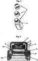
Fig. 1 shows a perspective view of an exemplary cap serving to explain certain features of the invention before and after mounting to a standard bottle as an example for a fluid container, -
Fig. 2 shows a cross-sectional view of the cap ofFig. 1 , -
Fig. 3 shows an exploded perspective view of the cap ofFig. 2 in a partly dismounted arrangement, -
Fig. 4 shows a schematic representation of a detail of the UV-transparent window, of the LED(s) and of an adjacent reflecting portion of the cap, -
Fig. 5 shows a similar schematic representation asFig. 4 of a modification of the cap which is an embodiment of the invention and includes a fluid channel that allows introduction or extraction of fluid through the cap while the same is in place on a container, and -
Fig. 6 shows a diagram of the control functions integrated into the cap. - The biocidal fluid purification cap of the present invention has a
cap body 3, formed in this example, from alower part 4 and anupper part 5 accomodating the functional elements including the LED(s) and those for driving the LED(s) as well as supporting elements there between so that these elements are sealed from the environment. Thelower part 4 of thecap body 3 includes an engagement feature 20 (seeFig. 2 ) for removably attaching the cap body to a mating engagement feature on an outer peripheral portion of a spout of a fluid container to hermetically close a spout opening. Theengagement feature 20 may include a threaded/screw type or bayonet type of engagement structure or an elastic insertion engagement by frictional or form-locking engagement, for example in the form of a tight rubber or plastic seal arrangement. The engagement feature is preferably one of the common types or standard threads used in connection with the containers that are normally used for holding purified water serving as laboratory supply for cell culture or molecular biology. The container for this type of use preferably has a volume of less than 2 liters and is formed of PET, glass or plastics material including an UV resistant additive agent, in the form of a bottle, a flask or a bag, which can be rigid or semi-rigid or flexible overall except for the spout portion. - To facilitate handling like screwing/unscrewing of the cap the upper part of the
cap body 3 and especially theupper part 5 but also thelower part 4 may include serrations or other forms of friction enhancing surface features 5a at external portions improving the grip of a user on the cap. Such a feature is schematically shown by the ribbed or knurledportion 5a inFig. 3 . This grip-portion may of course extend to other parts of the outer surface of the cap and the entire configuration of the cap is not restricted to the configuration shown in these figures. - Inside the cap body there is arranged at least one
LED 7a adapted to emit light in the UV-C range, i.e. preferably in a light range in the wavelength of 220 nm - 300 nm, preferably of 260 nm +/- 5 nm. The light emitting layers of a suitable LED type are epitaxial crystal growth of AIGaN on different wafer substrates, for example. The power of the LED(s) will be selected based on the desired intensity of the UV-light in the stated range which will normally depend on the size and volume of the fluid container with which the cap is to be used. Suitable UV LEDs are commercially available, e.g. from Seoul Optodevice, reference number CUD8AF1 A. - In the shown example, a plurality of LEDs are integrated on a printed circuit board (PCB) 7 to produce the desired power and to allow dimming or modulating of the power as well as a certain redundancy in case of failure of individual LED(s) as will be described further below.
- The PCB 7 is preferably made with a metal base and is arranged in the
cap body 3 so as to allow heat dissipation to the environment to the side that is remote or facing away from the side facing the interior of the container. Thus, the heat produced by the LED(s) can be more easily guided to the upper part of thecap body 3 and dissipated to the environment without substantial influence on the water in the container. In this case the friction enhancing feature 5a in the form of ribs etc. may additionally serve to increase the surface area to improve heat dissipation to the environment. - The cap also includes the necessary
electronic circuitry 15 for driving the LED(s) and a power supply for the electronic circuitry. Such power supply may include single-use or rechargeable batteries (not shown) received in the cap body and/or a connector and/or a contact-less transmitting means to an external power source (not shown). The connector is preferably in the form of a USB-socket or plug in accordance with standard charging equipment that is also used in connection with PC-peripherals or mobile telephones. In that case, the electronic circuitry also may include a function for charging the battery by external power supplied through the connector or contact-less through induction. - The
PCB 7 supporting the LED(s) 7a is mounted to the lower part of thecap body 4 by way of a holdingbracket 8 that is attached by a number of screws 8a to bosses 8b protruding from thelower part 4 of thecap body 3. In the mounted position a sealingring 12 and a UV-transparent window 6 is interposed between the receptacle in the lower part of thecap body 4 and thebracket 8. The UV-transparent window separates the LED(s) from the environment such that light emitted from the LED(s) may pass through thewindow 6 and enter the opening of the spout when the cap is attached to the spout of the container. The window is thus located above theengagement feature 20 as shown inFig. 2 . The sealingring 12 is optionally provided to guarantee that no liquid may enter beyond the UV-transparent window. - The UV-transparent window is made from quartz or silica glass, for example. The space between the lower and upper parts of the cap body may further receive a switch 13 (see
Figs. 2 and3 ) that is arranged so that it can detect removal of the cap from the spout of the container and can deactivate the operation of the LED(s) via suitable circuitry in response. This feature can protect the user from direct exposure to the UV-light of the LED(s) irradiated through the UV-transparent window when the cap is removed from the container and increases the lifetime of the batteries. For that purpose, the removal may be detected via the switch through a mechanical contact, i.e. in the form of a micro-switch lever, or contact-less by a suitable sensor replacing the mechanical switch. - The
electronic circuitry 15 integrated into the cap may also include an interface and a function for receiving control signals from a remote device to program function settings of the circuitry and/or to read out or read-in operational parameters or other data. This exchange of control signals can be through a cable, the connector for the external power source and/or contactless through known technical means for contactless data exchange. Theelectronic circuitry 15 in the cap may also include a function for modulating the drive power supplied to the LED(s) to allow dimming and/or intermittent operation of the LED(s) according to a predefined time and/or intensity schedule. The dimmed and/or intermittent operation is a means for managing the thermal dissipation of the LED(s) to avoid warming of the water in the container and may of course prolong the life-time of the battery. For example, the scheduled timing may be switched on at100% of its power until the batteries are empty or may allow a pulsed operation of all or selected ones of the LED(s) for short increments of time or a continuous irradiation at a reduced power level. The desired irradiation pattern can be selected through a further switch integrated into the cap body and accessible to the outside or may be programmed through the above- described data interface. An LED dimming function may be implemented, for example, by pulse width modulation of the power signal to the LED(s) which has a variable duty cycle in order to decrease the average intensity of the UV irradiation. For example, a 10% duty cycle (10ms on and 90ms off) may maintain a constant minimal level of UV light energy blocking microorganism regrowth while not affecting dramatically the lifetime of the power supply. Likewise, a heat sensor or thermistor may be integrated in the circuitry to detect the temperature of the LED(s) and trigger a dimming function to extend the lifetime of the LED(s) that would be impaired by excessive heat and/or reduce the risk of microorganism growth and vapor deposition on the internal walls of the container. - The various functions of the circuitry can be integrated all on the PCB supporting the LED(s) or may be located at different modular PCBs received at various spaces within the cap body. An exemplary separate PCB bearing certain electronic circuitry is shown in
Fig. 3 and is identified by thereference numeral 11. A general power orfunction switch 10 may be also integrated and accessible to the outside of the cap body. An example of the various circuit functions that might be integrated into the cap is shown inFig. 6 . In this diagram the control circuitry is summarized as "LED control module" and the external elements are shown as functional elements communicating therewith. - The cap body may include additional parts or covers that can be selectively removed, for example, to exchange batteries. Such an additional removable part is schematically represented by the
lid 9 inFig. 3 that is removably attached to the top side of the upper part of the cap body. - The
lid 9 may also be transparent to receive information or handling instructions regarding the use of the cap or the content of the container. It may also allow hand-written indications on it regarding the date and time of the first opening, etc. or may incorporate a display (i.e. a small LCD) or other indicators communicating with the LED control module. - To increase the amount of light directed to the spout, the
cap body 3 may be partially or completely made from a material that reflects UV-rays, for example, aluminum or PTFE or stainless steel, preferably at those portions upstream or downstream of the UV-transparent window 6 that are exposed to the light irradiation from the LED(s) 7a. Such UV-rayreflective structures 14 are schematically shown inFig. 4 and they are arranged to direct the rays towards the spout opening. If necessary to avoid oxidizing of aluminum, for example, the material may be coated or covered with an oxidizing preventing layer of a UV-transparent material such as silica or quartz. The UV-reflecting material may also be applied in the form of a coating on other supporting material and restricted to those parts that are actually exposed to UV-radiation during use. - In order to signal operation of the UV-LED(s) to a user an additional light source in the visible range, for example, an LED irradiating light in the visible range, may be integrated on the PCB such that its light is at least partially visible from outside.
- In another modification that is schematically shown in
Fig. 5 and which is an embodiment of the invention acap body 3 includes afluid opening 16 communicating with or accessible to the outside of the cap body and afluid opening 17 communicating with the spout opening of the container when the cap is attached to the spout as well as afluid channel 18 extending between thesefluid openings transparent window 6 and a further UV-transparent window 9 facing the opening of the spout to allow, in operation, the light emitted from the LED(s) to pass through the first UV-transparent window 6 and then through thefluid channel 18, before passing the second UV-transparent window 19 and entering the spout opening of the container. This modification allows introduction and/or extraction of fluid into/out from the container while the cap remains arranged on the spout, for example by way of a syringe or an inlet tubing coupled with thefluid opening 16. A seal or syringe connection including a check valve may be provided at theopening 16 to maintain the sterility of the interior of the container. An additional (not shown) vent filter may be included into the cap body if larger amounts of fluid are to be filled into the container through such a fluid channel. The structure may also be used to extract fluid from the container without removing the purification cap, for example by turning the container upside down in a position with the cap facing downward and extracting the fluid through a syringe coupled to thefluid opening 16 or valve. A suitable further seal arrangement may be provided at thefluid opening 17 to maintain the sterility of the interior of the cap and container. - The biocidal fluid purification cap for a fluid container of the invention provides a number of advantages which includes the possibility to irradiate small water volumes in standard containers and maintain their sterility over considerable time periods even after the container has been opened once. The wavelength of the UV-LED(s) is narrow and deep enough to be completely blocked by most plastics materials used for forming the containers. The integration of the LED(s) into the top portion of the cap allows secure heat dissipation to the environment involving warming of the water and microorganism growth promotion in the container. It also expands the lifetime of the LED(s). This aspect may be further improved by the dimming functions integrated into the circuitry of the purification cap for driving the LED(s). The power consumption of the common LED(s) in the wavelength is much lower than mercury-based solutions allowing for power consumption savings and extension of the use time. As compared to mercury-based purification concepts, there is less degradation of plastic from the tank and leaching of organic into the water and no risk of hazardous contamination.
Claims (13)
- A biocidal fluid purification cap (2) for a fluid container (1), including:a cap body (3) including an engagement feature (20) for removably attaching the cap body (3) to a mating engagement feature on a spout of the fluid container (1) to hermetically close a spout opening,at least one LED (7a) adapted to emit light in the UV-C range,electronic circuitry (15) for driving the LED(s) (7a), anda power supply for the electronic circuitry (15),wherein said LED(s) (7a) is/are arranged in said cap body (3) so as to be separated from the environment by an UV-transparent window (6) provided in the cap body (3) such that light emitted from said LED(s) (7a) enters the opening of the spout when the cap (2) is attached to the spout of the container (1), andwherein said cap body (3) includes a first fluid opening (16) to the outside of the cap body (3) and a second fluid opening (17) to the spout opening of the container (1) when the cap (2) is attached to the spout, and a fluid channel (8) extending between the first fluid opening (16) and the second fluid opening (17) and passing between the UV-transparent window (6) and a further UV-transparent window (19) facing the opening of the spout to allow, in operation, the light emitted from the LED(s) (7a) to pass through the fluid flowing in the channel (18) before entering the spout opening of the container (1).
- The biocidal fluid purification cap (2) according to claim 1, wherein said power supply comprises a battery received in the cap body (3) and/or a connector and/or a contact-less transmitting means to an external power source.
- The biocidal fluid purification cap (2) according to claim 2, wherein said electronic circuitry (15) includes a function for charging said battery by external power supplied through said connector and/or said contact-less transmitting means.
- The biocidal fluid purification cap (2) according to any one of claims 1 to 3, wherein said electronic circuitry (15) includes an interface and function for receiving a control signal from a remote device to program function settings of the circuitry (15).
- The biocidal fluid purification cap (2) according to any one of claims 1 to 4, wherein said electronic circuitry (15) includes a function for modulating the drive power supplied to the LED(s) (7a) to allow dimming and/or intermittent operation of the LED(s) (7a) according to a predefined time and/or intensity schedule.
- The biocidal fluid purification cap (2) according to any one of claims 1 to 5, wherein said cap body (3) includes a switch (13) that is adapted to detect removal of the cap body (3) from the spout of the container (1) and to deactivate the operation of the LED(s) (7a) via the circuitry in response.
- The biocidal fluid purification cap (2) according to any one of claims 1 to 6, wherein said electronic circuitry (15) and said LED(s) (7a) are provided on a PCB (7) with a metal base, and said PCB (7) is arranged in the cap body (3) to allow heat dissipation to the environment.
- The biocidal fluid purification cap (2) according to any one of claims 1 to 7, wherein said LED(s) (7a) is/are adapted to emit light in the wavelength range of 220nm - 300nm, preferably of 260nm +/- 5nm.
- The biocidal fluid purification cap (2) according to any one of claims 1 to 8, wherein said cap body (3) is at least partially made from or covered with a material that reflects UV-rays, preferably aluminum or PTFE or stainless steel, if necessary covered with an oxidizing preventing layer of an UV- transparent material, preferably at portions exposed to the light irradiation from the LED(s) (7a).
- The biocidal fluid purification cap (2) according to any one of claims 1 to 9, wherein a portion of the cap body (3) between the UV-transparent window (6) and the spout opening is formed as a reflector (14) for directing the light rays emitted from the LED(s) (7a) towards the spout opening.
- The biocidal fluid purification cap (2) according to any one of claims 1 to 10, wherein said engagement feature (20) for removably attaching the cap body (3) to the spout of the container (1) includes a threaded/screw or a bayonet-type or elastic insertion engagement structure.
- The biocidal fluid purification cap (2) according to any one of claims 1 to 11, wherein said container (1) is a bottle, flask or bag, preferably with a volume of less than 2 liters, preferably made of an UV-absorbent material, preferably PET, glass or plastics material including an UV-resistant additive agent.
- The biocidal fluid purification cap (2) according to any one of claims 1 to 12, wherein said UV-transparent window (6,19) is made from quartz glass or silica glass.
Applications Claiming Priority (3)
| Application Number | Priority Date | Filing Date | Title |
|---|---|---|---|
| EP13290114 | 2013-05-22 | ||
| EP14720488.7A EP2999667B1 (en) | 2013-05-22 | 2014-04-24 | Biocidal purification device |
| PCT/EP2014/001096 WO2014187524A1 (en) | 2013-05-22 | 2014-04-24 | Biocidal purification device |
Related Parent Applications (2)
| Application Number | Title | Priority Date | Filing Date |
|---|---|---|---|
| EP14720488.7A Division-Into EP2999667B1 (en) | 2013-05-22 | 2014-04-24 | Biocidal purification device |
| EP14720488.7A Division EP2999667B1 (en) | 2013-05-22 | 2014-04-24 | Biocidal purification device |
Publications (2)
| Publication Number | Publication Date |
|---|---|
| EP3170796A1 true EP3170796A1 (en) | 2017-05-24 |
| EP3170796B1 EP3170796B1 (en) | 2019-02-27 |
Family
ID=48782263
Family Applications (2)
| Application Number | Title | Priority Date | Filing Date |
|---|---|---|---|
| EP14720488.7A Active EP2999667B1 (en) | 2013-05-22 | 2014-04-24 | Biocidal purification device |
| EP16202186.9A Active EP3170796B1 (en) | 2013-05-22 | 2014-04-24 | Biocidal purification device |
Family Applications Before (1)
| Application Number | Title | Priority Date | Filing Date |
|---|---|---|---|
| EP14720488.7A Active EP2999667B1 (en) | 2013-05-22 | 2014-04-24 | Biocidal purification device |
Country Status (6)
| Country | Link |
|---|---|
| US (2) | US9475708B2 (en) |
| EP (2) | EP2999667B1 (en) |
| JP (1) | JP6506741B2 (en) |
| CN (1) | CN105228956B (en) |
| ES (2) | ES2622755T3 (en) |
| WO (1) | WO2014187524A1 (en) |
Cited By (1)
| Publication number | Priority date | Publication date | Assignee | Title |
|---|---|---|---|---|
| US10180248B2 (en) | 2015-09-02 | 2019-01-15 | ProPhotonix Limited | LED lamp with sensing capabilities |
Families Citing this family (34)
| Publication number | Priority date | Publication date | Assignee | Title |
|---|---|---|---|---|
| ES2622755T3 (en) | 2013-05-22 | 2017-07-07 | Merck Patent Gmbh | Biocidal Purification Device |
| US10246348B2 (en) | 2015-06-08 | 2019-04-02 | Rayvio Corporation | Ultraviolet disinfection system |
| US9540252B1 (en) | 2015-06-08 | 2017-01-10 | Rayvio Corporation | Ultraviolet disinfection system |
| CN108698857B (en) * | 2016-02-18 | 2021-12-31 | 昕诺飞控股有限公司 | Fluid purification system and method |
| JP2017159251A (en) * | 2016-03-10 | 2017-09-14 | パナソニックIpマネジメント株式会社 | Sterilization container |
| WO2017185216A1 (en) * | 2016-04-25 | 2017-11-02 | 圆融健康科技(深圳)有限公司 | Sterilizer, sterilization cover having same, storage apparatus, and food transport box |
| WO2017185217A1 (en) * | 2016-04-25 | 2017-11-02 | 圆融健康科技(深圳)有限公司 | Sterilization cover, storage apparatus, water bottle, milk bottle, medicine bottle, and cosmetic bottle |
| JP6591932B2 (en) * | 2016-06-09 | 2019-10-16 | 株式会社日立ハイテクノロジーズ | Automatic analyzer |
| CN108298636B (en) * | 2017-01-12 | 2021-09-03 | 财团法人工业技术研究院 | Portable purifying device |
| WO2018190684A2 (en) | 2017-04-14 | 2018-10-18 | 서울바이오시스 주식회사 | Sterilization module and water purifying device including same |
| KR102533593B1 (en) * | 2017-04-14 | 2023-05-18 | 서울바이오시스 주식회사 | sterilization module, water purifying device and system comprising the water purifying device |
| KR102529751B1 (en) | 2017-09-26 | 2023-05-08 | 서울바이오시스 주식회사 | Portable water bottle |
| WO2019072205A1 (en) * | 2017-10-11 | 2019-04-18 | The Hong Kong University Of Science And Technology | Asynchronous intermittent lighting for rapid surface disinfection |
| CN111212816B (en) * | 2017-10-17 | 2023-04-21 | 默克专利股份公司 | Irradiation device for irradiation reactor for treating fluid and irradiation reactor |
| US11173221B2 (en) * | 2017-10-31 | 2021-11-16 | Sensor Electronic Technology, Inc. | Ultraviolet disinfection for a water bottle |
| JP7034689B2 (en) | 2017-12-01 | 2022-03-14 | 株式会社日立ハイテク | Automatic analyzer |
| US10266426B1 (en) * | 2017-12-07 | 2019-04-23 | Mag Aerospace Industries, Llc | UV water treatment in portable water tank |
| DE102017131306A1 (en) * | 2017-12-27 | 2019-06-27 | Forschungsverbund Berlin E.V. | Device for disinfecting liquid in a vessel |
| CN108476768A (en) * | 2018-06-11 | 2018-09-04 | 中国科学院南京地理与湖泊研究所 | A kind of low transparency water body submerged vegetation light compensating apparatus and method |
| ES2941364T3 (en) * | 2018-06-11 | 2023-05-22 | Procter & Gamble | Photoactivator device for washing machine |
| GB2576346B (en) * | 2018-08-15 | 2022-06-29 | Vws Uk Ltd | Water purifying apparatus and method |
| EP3873853B1 (en) * | 2018-11-02 | 2025-09-17 | Crystal IS, Inc. | Systems and methods for fluid disinfection with ultraviolet light |
| CN109574342B (en) * | 2019-01-07 | 2024-05-07 | 李晓惠 | UV sterilization cup |
| US11225363B2 (en) | 2019-02-21 | 2022-01-18 | Microlyses, LLC | Water purification cap |
| USD899926S1 (en) | 2019-02-21 | 2020-10-27 | Microlyscs, Llc | Bottle cap |
| US11952293B2 (en) | 2019-03-07 | 2024-04-09 | International Water-Guard Industries Inc. | Apparatus for disinfecting a fluid |
| WO2021021972A1 (en) | 2019-07-31 | 2021-02-04 | Access Business Group International Llc | Water treatment system |
| US20210162089A1 (en) * | 2020-02-10 | 2021-06-03 | Thomas Wolfgang Zimmermann | Ultraviolet face mask |
| US11007292B1 (en) | 2020-05-01 | 2021-05-18 | Uv Innovators, Llc | Automatic power compensation in ultraviolet (UV) light emission device, and related methods of use, particularly suited for decontamination |
| US11214499B2 (en) | 2020-05-14 | 2022-01-04 | Microlyscs, Llc | Water sterilization cap with removable particulate filter and/or hydration meter |
| JP6864398B1 (en) * | 2020-07-16 | 2021-04-28 | 株式会社サンコーデバイス | Ultraviolet irradiation device, ultraviolet irradiation control device, ultraviolet irradiation system |
| JP7532147B2 (en) * | 2020-08-25 | 2024-08-13 | 東芝ライテック株式会社 | Lighting equipment |
| SE544686C2 (en) * | 2020-12-15 | 2022-10-18 | Bluewater Sweden Ab | Container with UV purification |
| CN116573289A (en) * | 2023-06-21 | 2023-08-11 | 厦门斯坦瑞科技有限公司 | A kind of safe sterilization washing and protecting bottle |
Citations (6)
| Publication number | Priority date | Publication date | Assignee | Title |
|---|---|---|---|---|
| US6579495B1 (en) | 2000-07-27 | 2003-06-17 | Hydro Photon, Inc. | Hand-held ultraviolet water purification system using solid state devices |
| US20050258108A1 (en) * | 2004-05-24 | 2005-11-24 | Eric Sanford | Container with purifier |
| WO2010104096A1 (en) | 2009-03-13 | 2010-09-16 | パナソニック電工株式会社 | Water purifier |
| US20110114546A1 (en) * | 2009-11-17 | 2011-05-19 | Barsky Barry E | Water Container Having Germicidal Water Purification Unit |
| US20130075312A1 (en) * | 2011-09-22 | 2013-03-28 | Keith Ervin | Water Purifier |
| KR20130045884A (en) * | 2012-12-05 | 2013-05-06 | 김용진 | The ultraviolet rays sterilizatiion device and pitcher |
Family Cites Families (12)
| Publication number | Priority date | Publication date | Assignee | Title |
|---|---|---|---|---|
| BRPI1006208A2 (en) * | 2009-03-26 | 2021-02-23 | Koninklijke Philips Electronics N. V. | disinfection device |
| JP5374697B2 (en) * | 2009-07-09 | 2013-12-25 | ユーヴィックス株式会社 | UV sterilization water purifier and UV LED unit used for it |
| CN101703356A (en) * | 2009-11-03 | 2010-05-12 | 上海大学 | Ultraviolet sterilizing drinking cup |
| CN201577956U (en) * | 2009-12-25 | 2010-09-15 | 山西乐百利特科技有限责任公司 | Ultraviolet germicidal drinking cup |
| US20110174993A1 (en) * | 2010-01-18 | 2011-07-21 | Camelbak Products, Llc | Water purifying drink containers |
| EP2829518A4 (en) * | 2012-03-21 | 2015-09-30 | Seoul Viosys Co Ltd | Water purification system using ultraviolet leds |
| CN202760846U (en) * | 2012-06-02 | 2013-03-06 | 上海大学 | Ultraviolet LED sterilizing water drinking cup |
| US8975596B1 (en) * | 2012-07-20 | 2015-03-10 | Meridian Design, Inc. | Water purifying drink containers |
| CN102755654B (en) * | 2012-08-06 | 2014-05-28 | 上海上远齿科技术有限公司 | Sterilizer of oral articles |
| CN202760863U (en) * | 2012-08-29 | 2013-03-06 | 福建二菱电子有限公司 | Ultraviolet sterilization cup |
| ES2622755T3 (en) | 2013-05-22 | 2017-07-07 | Merck Patent Gmbh | Biocidal Purification Device |
| US20150307368A1 (en) * | 2014-04-25 | 2015-10-29 | Richard D. Yanke | Ultraviolet Light Purification Drinking System |
-
2014
- 2014-04-24 ES ES14720488.7T patent/ES2622755T3/en active Active
- 2014-04-24 WO PCT/EP2014/001096 patent/WO2014187524A1/en not_active Ceased
- 2014-04-24 EP EP14720488.7A patent/EP2999667B1/en active Active
- 2014-04-24 US US14/889,603 patent/US9475708B2/en active Active
- 2014-04-24 JP JP2016514286A patent/JP6506741B2/en active Active
- 2014-04-24 EP EP16202186.9A patent/EP3170796B1/en active Active
- 2014-04-24 ES ES16202186T patent/ES2724428T3/en active Active
- 2014-04-24 CN CN201480029428.7A patent/CN105228956B/en active Active
-
2016
- 2016-09-20 US US15/270,529 patent/US9695062B2/en active Active
Patent Citations (6)
| Publication number | Priority date | Publication date | Assignee | Title |
|---|---|---|---|---|
| US6579495B1 (en) | 2000-07-27 | 2003-06-17 | Hydro Photon, Inc. | Hand-held ultraviolet water purification system using solid state devices |
| US20050258108A1 (en) * | 2004-05-24 | 2005-11-24 | Eric Sanford | Container with purifier |
| WO2010104096A1 (en) | 2009-03-13 | 2010-09-16 | パナソニック電工株式会社 | Water purifier |
| US20110114546A1 (en) * | 2009-11-17 | 2011-05-19 | Barsky Barry E | Water Container Having Germicidal Water Purification Unit |
| US20130075312A1 (en) * | 2011-09-22 | 2013-03-28 | Keith Ervin | Water Purifier |
| KR20130045884A (en) * | 2012-12-05 | 2013-05-06 | 김용진 | The ultraviolet rays sterilizatiion device and pitcher |
Cited By (1)
| Publication number | Priority date | Publication date | Assignee | Title |
|---|---|---|---|---|
| US10180248B2 (en) | 2015-09-02 | 2019-01-15 | ProPhotonix Limited | LED lamp with sensing capabilities |
Also Published As
| Publication number | Publication date |
|---|---|
| US9475708B2 (en) | 2016-10-25 |
| JP2016525906A (en) | 2016-09-01 |
| CN105228956B (en) | 2018-12-25 |
| JP6506741B2 (en) | 2019-04-24 |
| EP2999667A1 (en) | 2016-03-30 |
| CN105228956A (en) | 2016-01-06 |
| US9695062B2 (en) | 2017-07-04 |
| US20170029292A1 (en) | 2017-02-02 |
| EP2999667B1 (en) | 2017-02-01 |
| US20160107904A1 (en) | 2016-04-21 |
| ES2724428T3 (en) | 2019-09-10 |
| WO2014187524A1 (en) | 2014-11-27 |
| EP3170796B1 (en) | 2019-02-27 |
| ES2622755T3 (en) | 2017-07-07 |
Similar Documents
| Publication | Publication Date | Title |
|---|---|---|
| US9695062B2 (en) | Biocidal purification device | |
| US6514405B1 (en) | Portable water purifier with ultraviolet light source | |
| US6475433B2 (en) | Method and apparatus for verifying ultraviolet sterilization | |
| US20140202948A1 (en) | Portable Liquid Purifying Apparatus | |
| US20170190598A1 (en) | Device for uv-led liquid monitoring and treatment | |
| CN209536957U (en) | Drinking water apparatus | |
| KR20090081658A (en) | Sterilizer for Drinking Water Storage Tank | |
| US9975788B2 (en) | Optical fluid treatment device | |
| JP6328527B2 (en) | UV sterilizer | |
| KR20110010470A (en) | LED fish tank with sterilization function using LED UV lamp and ozone | |
| JP6258163B2 (en) | Ultraviolet-transmissive window material having photocatalytic function and ultraviolet irradiation apparatus having the window material | |
| CN209136313U (en) | Vacuum flask with ultraviolet-sterilization function | |
| KR20210075260A (en) | IoT-based Portable drinking container having UV LED | |
| KR102097168B1 (en) | Bottle cap for sterilizing beverages with uv lamp | |
| WO2000079246A1 (en) | Methods and apparatus for disinfecting and sterilizing fluids using ultraviolet radiation | |
| JP6189804B2 (en) | Composition for photocatalyst coating | |
| KR20120140564A (en) | Faucet | |
| CN217498744U (en) | Disinfection unit and disinfection device | |
| CN209137437U (en) | Rodlike sterilizer and beverage bottle containing the sterilizer | |
| WO2017086874A1 (en) | Liquid purifying drink container device with field emission uv light source | |
| CN110141090A (en) | Sterilization cup lids and cups | |
| KR20190056542A (en) | button Sterilize tumbler | |
| KR20170008122A (en) | Auto Sterilize tumbler |
Legal Events
| Date | Code | Title | Description |
|---|---|---|---|
| PUAI | Public reference made under article 153(3) epc to a published international application that has entered the european phase |
Free format text: ORIGINAL CODE: 0009012 |
|
| STAA | Information on the status of an ep patent application or granted ep patent |
Free format text: STATUS: REQUEST FOR EXAMINATION WAS MADE |
|
| 17P | Request for examination filed |
Effective date: 20161205 |
|
| AC | Divisional application: reference to earlier application |
Ref document number: 2999667 Country of ref document: EP Kind code of ref document: P |
|
| AK | Designated contracting states |
Kind code of ref document: A1 Designated state(s): AL AT BE BG CH CY CZ DE DK EE ES FI FR GB GR HR HU IE IS IT LI LT LU LV MC MK MT NL NO PL PT RO RS SE SI SK SM TR |
|
| RIN1 | Information on inventor provided before grant (corrected) |
Inventor name: GROSS, JULIEN Inventor name: BOLE, JULIEN Inventor name: KANO, ICHIRO Inventor name: GAIGNET, YVES Inventor name: RAJAGOPALAN, PASCAL |
|
| STAA | Information on the status of an ep patent application or granted ep patent |
Free format text: STATUS: EXAMINATION IS IN PROGRESS |
|
| 17Q | First examination report despatched |
Effective date: 20171122 |
|
| GRAP | Despatch of communication of intention to grant a patent |
Free format text: ORIGINAL CODE: EPIDOSNIGR1 |
|
| STAA | Information on the status of an ep patent application or granted ep patent |
Free format text: STATUS: GRANT OF PATENT IS INTENDED |
|
| RIC1 | Information provided on ipc code assigned before grant |
Ipc: C02F 103/02 20060101ALN20180807BHEP Ipc: C02F 1/32 20060101AFI20180807BHEP |
|
| INTG | Intention to grant announced |
Effective date: 20180912 |
|
| GRAS | Grant fee paid |
Free format text: ORIGINAL CODE: EPIDOSNIGR3 |
|
| GRAA | (expected) grant |
Free format text: ORIGINAL CODE: 0009210 |
|
| STAA | Information on the status of an ep patent application or granted ep patent |
Free format text: STATUS: THE PATENT HAS BEEN GRANTED |
|
| AC | Divisional application: reference to earlier application |
Ref document number: 2999667 Country of ref document: EP Kind code of ref document: P |
|
| AK | Designated contracting states |
Kind code of ref document: B1 Designated state(s): AL AT BE BG CH CY CZ DE DK EE ES FI FR GB GR HR HU IE IS IT LI LT LU LV MC MK MT NL NO PL PT RO RS SE SI SK SM TR |
|
| REG | Reference to a national code |
Ref country code: GB Ref legal event code: FG4D |
|
| REG | Reference to a national code |
Ref country code: CH Ref legal event code: EP |
|
| REG | Reference to a national code |
Ref country code: AT Ref legal event code: REF Ref document number: 1101035 Country of ref document: AT Kind code of ref document: T Effective date: 20190315 |
|
| REG | Reference to a national code |
Ref country code: IE Ref legal event code: FG4D |
|
| REG | Reference to a national code |
Ref country code: DE Ref legal event code: R096 Ref document number: 602014042157 Country of ref document: DE |
|
| REG | Reference to a national code |
Ref country code: CH Ref legal event code: NV Representative=s name: E. BLUM AND CO. AG PATENT- UND MARKENANWAELTE , CH |
|
| REG | Reference to a national code |
Ref country code: NL Ref legal event code: FP |
|
| REG | Reference to a national code |
Ref country code: LT Ref legal event code: MG4D |
|
| PG25 | Lapsed in a contracting state [announced via postgrant information from national office to epo] |
Ref country code: FI Free format text: LAPSE BECAUSE OF FAILURE TO SUBMIT A TRANSLATION OF THE DESCRIPTION OR TO PAY THE FEE WITHIN THE PRESCRIBED TIME-LIMIT Effective date: 20190227 Ref country code: NO Free format text: LAPSE BECAUSE OF FAILURE TO SUBMIT A TRANSLATION OF THE DESCRIPTION OR TO PAY THE FEE WITHIN THE PRESCRIBED TIME-LIMIT Effective date: 20190527 Ref country code: LT Free format text: LAPSE BECAUSE OF FAILURE TO SUBMIT A TRANSLATION OF THE DESCRIPTION OR TO PAY THE FEE WITHIN THE PRESCRIBED TIME-LIMIT Effective date: 20190227 Ref country code: PT Free format text: LAPSE BECAUSE OF FAILURE TO SUBMIT A TRANSLATION OF THE DESCRIPTION OR TO PAY THE FEE WITHIN THE PRESCRIBED TIME-LIMIT Effective date: 20190627 Ref country code: SE Free format text: LAPSE BECAUSE OF FAILURE TO SUBMIT A TRANSLATION OF THE DESCRIPTION OR TO PAY THE FEE WITHIN THE PRESCRIBED TIME-LIMIT Effective date: 20190227 |
|
| PG25 | Lapsed in a contracting state [announced via postgrant information from national office to epo] |
Ref country code: LV Free format text: LAPSE BECAUSE OF FAILURE TO SUBMIT A TRANSLATION OF THE DESCRIPTION OR TO PAY THE FEE WITHIN THE PRESCRIBED TIME-LIMIT Effective date: 20190227 Ref country code: RS Free format text: LAPSE BECAUSE OF FAILURE TO SUBMIT A TRANSLATION OF THE DESCRIPTION OR TO PAY THE FEE WITHIN THE PRESCRIBED TIME-LIMIT Effective date: 20190227 Ref country code: IS Free format text: LAPSE BECAUSE OF FAILURE TO SUBMIT A TRANSLATION OF THE DESCRIPTION OR TO PAY THE FEE WITHIN THE PRESCRIBED TIME-LIMIT Effective date: 20190627 Ref country code: BG Free format text: LAPSE BECAUSE OF FAILURE TO SUBMIT A TRANSLATION OF THE DESCRIPTION OR TO PAY THE FEE WITHIN THE PRESCRIBED TIME-LIMIT Effective date: 20190527 Ref country code: HR Free format text: LAPSE BECAUSE OF FAILURE TO SUBMIT A TRANSLATION OF THE DESCRIPTION OR TO PAY THE FEE WITHIN THE PRESCRIBED TIME-LIMIT Effective date: 20190227 Ref country code: GR Free format text: LAPSE BECAUSE OF FAILURE TO SUBMIT A TRANSLATION OF THE DESCRIPTION OR TO PAY THE FEE WITHIN THE PRESCRIBED TIME-LIMIT Effective date: 20190528 |
|
| REG | Reference to a national code |
Ref country code: ES Ref legal event code: FG2A Ref document number: 2724428 Country of ref document: ES Kind code of ref document: T3 Effective date: 20190910 |
|
| REG | Reference to a national code |
Ref country code: AT Ref legal event code: MK05 Ref document number: 1101035 Country of ref document: AT Kind code of ref document: T Effective date: 20190227 |
|
| PG25 | Lapsed in a contracting state [announced via postgrant information from national office to epo] |
Ref country code: DK Free format text: LAPSE BECAUSE OF FAILURE TO SUBMIT A TRANSLATION OF THE DESCRIPTION OR TO PAY THE FEE WITHIN THE PRESCRIBED TIME-LIMIT Effective date: 20190227 Ref country code: EE Free format text: LAPSE BECAUSE OF FAILURE TO SUBMIT A TRANSLATION OF THE DESCRIPTION OR TO PAY THE FEE WITHIN THE PRESCRIBED TIME-LIMIT Effective date: 20190227 Ref country code: SK Free format text: LAPSE BECAUSE OF FAILURE TO SUBMIT A TRANSLATION OF THE DESCRIPTION OR TO PAY THE FEE WITHIN THE PRESCRIBED TIME-LIMIT Effective date: 20190227 Ref country code: AL Free format text: LAPSE BECAUSE OF FAILURE TO SUBMIT A TRANSLATION OF THE DESCRIPTION OR TO PAY THE FEE WITHIN THE PRESCRIBED TIME-LIMIT Effective date: 20190227 Ref country code: CZ Free format text: LAPSE BECAUSE OF FAILURE TO SUBMIT A TRANSLATION OF THE DESCRIPTION OR TO PAY THE FEE WITHIN THE PRESCRIBED TIME-LIMIT Effective date: 20190227 Ref country code: RO Free format text: LAPSE BECAUSE OF FAILURE TO SUBMIT A TRANSLATION OF THE DESCRIPTION OR TO PAY THE FEE WITHIN THE PRESCRIBED TIME-LIMIT Effective date: 20190227 |
|
| REG | Reference to a national code |
Ref country code: DE Ref legal event code: R097 Ref document number: 602014042157 Country of ref document: DE |
|
| PG25 | Lapsed in a contracting state [announced via postgrant information from national office to epo] |
Ref country code: SM Free format text: LAPSE BECAUSE OF FAILURE TO SUBMIT A TRANSLATION OF THE DESCRIPTION OR TO PAY THE FEE WITHIN THE PRESCRIBED TIME-LIMIT Effective date: 20190227 Ref country code: PL Free format text: LAPSE BECAUSE OF FAILURE TO SUBMIT A TRANSLATION OF THE DESCRIPTION OR TO PAY THE FEE WITHIN THE PRESCRIBED TIME-LIMIT Effective date: 20190227 |
|
| PG25 | Lapsed in a contracting state [announced via postgrant information from national office to epo] |
Ref country code: MC Free format text: LAPSE BECAUSE OF FAILURE TO SUBMIT A TRANSLATION OF THE DESCRIPTION OR TO PAY THE FEE WITHIN THE PRESCRIBED TIME-LIMIT Effective date: 20190227 Ref country code: AT Free format text: LAPSE BECAUSE OF FAILURE TO SUBMIT A TRANSLATION OF THE DESCRIPTION OR TO PAY THE FEE WITHIN THE PRESCRIBED TIME-LIMIT Effective date: 20190227 Ref country code: LU Free format text: LAPSE BECAUSE OF NON-PAYMENT OF DUE FEES Effective date: 20190424 |
|
| PLBE | No opposition filed within time limit |
Free format text: ORIGINAL CODE: 0009261 |
|
| STAA | Information on the status of an ep patent application or granted ep patent |
Free format text: STATUS: NO OPPOSITION FILED WITHIN TIME LIMIT |
|
| 26N | No opposition filed |
Effective date: 20191128 |
|
| PG25 | Lapsed in a contracting state [announced via postgrant information from national office to epo] |
Ref country code: SI Free format text: LAPSE BECAUSE OF FAILURE TO SUBMIT A TRANSLATION OF THE DESCRIPTION OR TO PAY THE FEE WITHIN THE PRESCRIBED TIME-LIMIT Effective date: 20190227 |
|
| PG25 | Lapsed in a contracting state [announced via postgrant information from national office to epo] |
Ref country code: TR Free format text: LAPSE BECAUSE OF FAILURE TO SUBMIT A TRANSLATION OF THE DESCRIPTION OR TO PAY THE FEE WITHIN THE PRESCRIBED TIME-LIMIT Effective date: 20190227 |
|
| PG25 | Lapsed in a contracting state [announced via postgrant information from national office to epo] |
Ref country code: IE Free format text: LAPSE BECAUSE OF NON-PAYMENT OF DUE FEES Effective date: 20190424 |
|
| PG25 | Lapsed in a contracting state [announced via postgrant information from national office to epo] |
Ref country code: CY Free format text: LAPSE BECAUSE OF FAILURE TO SUBMIT A TRANSLATION OF THE DESCRIPTION OR TO PAY THE FEE WITHIN THE PRESCRIBED TIME-LIMIT Effective date: 20190227 |
|
| PG25 | Lapsed in a contracting state [announced via postgrant information from national office to epo] |
Ref country code: HU Free format text: LAPSE BECAUSE OF FAILURE TO SUBMIT A TRANSLATION OF THE DESCRIPTION OR TO PAY THE FEE WITHIN THE PRESCRIBED TIME-LIMIT; INVALID AB INITIO Effective date: 20140424 Ref country code: MT Free format text: LAPSE BECAUSE OF FAILURE TO SUBMIT A TRANSLATION OF THE DESCRIPTION OR TO PAY THE FEE WITHIN THE PRESCRIBED TIME-LIMIT Effective date: 20190227 |
|
| PG25 | Lapsed in a contracting state [announced via postgrant information from national office to epo] |
Ref country code: MK Free format text: LAPSE BECAUSE OF FAILURE TO SUBMIT A TRANSLATION OF THE DESCRIPTION OR TO PAY THE FEE WITHIN THE PRESCRIBED TIME-LIMIT Effective date: 20190227 |
|
| P01 | Opt-out of the competence of the unified patent court (upc) registered |
Effective date: 20230518 |
|
| PGFP | Annual fee paid to national office [announced via postgrant information from national office to epo] |
Ref country code: DE Payment date: 20250319 Year of fee payment: 12 |
|
| PGFP | Annual fee paid to national office [announced via postgrant information from national office to epo] |
Ref country code: ES Payment date: 20250502 Year of fee payment: 12 |
|
| PGFP | Annual fee paid to national office [announced via postgrant information from national office to epo] |
Ref country code: CH Payment date: 20250501 Year of fee payment: 12 |
|
| PGFP | Annual fee paid to national office [announced via postgrant information from national office to epo] |
Ref country code: GB Payment date: 20260320 Year of fee payment: 13 |
|
| PGFP | Annual fee paid to national office [announced via postgrant information from national office to epo] |
Ref country code: BE Payment date: 20260319 Year of fee payment: 13 Ref country code: IT Payment date: 20260319 Year of fee payment: 13 |
|
| PGFP | Annual fee paid to national office [announced via postgrant information from national office to epo] |
Ref country code: NL Payment date: 20260319 Year of fee payment: 13 |
|
| PGFP | Annual fee paid to national office [announced via postgrant information from national office to epo] |
Ref country code: FR Payment date: 20260320 Year of fee payment: 13 |