EP3170704A2 - Methods and apparatus for determining seatbelt status - Google Patents
Methods and apparatus for determining seatbelt status Download PDFInfo
- Publication number
- EP3170704A2 EP3170704A2 EP16194342.8A EP16194342A EP3170704A2 EP 3170704 A2 EP3170704 A2 EP 3170704A2 EP 16194342 A EP16194342 A EP 16194342A EP 3170704 A2 EP3170704 A2 EP 3170704A2
- Authority
- EP
- European Patent Office
- Prior art keywords
- seatbelt
- seat
- unfastened
- status
- occupied
- Prior art date
- Legal status (The legal status is an assumption and is not a legal conclusion. Google has not performed a legal analysis and makes no representation as to the accuracy of the status listed.)
- Granted
Links
Images




Classifications
-
- B—PERFORMING OPERATIONS; TRANSPORTING
- B64—AIRCRAFT; AVIATION; COSMONAUTICS
- B64D—EQUIPMENT FOR FITTING IN OR TO AIRCRAFT; FLIGHT SUITS; PARACHUTES; ARRANGEMENT OR MOUNTING OF POWER PLANTS OR PROPULSION TRANSMISSIONS IN AIRCRAFT
- B64D45/00—Aircraft indicators or protectors not otherwise provided for
-
- B—PERFORMING OPERATIONS; TRANSPORTING
- B60—VEHICLES IN GENERAL
- B60R—VEHICLES, VEHICLE FITTINGS, OR VEHICLE PARTS, NOT OTHERWISE PROVIDED FOR
- B60R22/00—Safety belts or body harnesses in vehicles
- B60R22/48—Control systems, alarms, or interlock systems, for the correct application of the belt or harness
-
- B—PERFORMING OPERATIONS; TRANSPORTING
- B64—AIRCRAFT; AVIATION; COSMONAUTICS
- B64D—EQUIPMENT FOR FITTING IN OR TO AIRCRAFT; FLIGHT SUITS; PARACHUTES; ARRANGEMENT OR MOUNTING OF POWER PLANTS OR PROPULSION TRANSMISSIONS IN AIRCRAFT
- B64D11/00—Passenger or crew accommodation; Flight-deck installations not otherwise provided for
- B64D11/06—Arrangements of seats, or adaptations or details specially adapted for aircraft seats
- B64D11/062—Belts or other passenger restraint means for passenger seats
-
- A—HUMAN NECESSITIES
- A44—HABERDASHERY; JEWELLERY
- A44B—BUTTONS, PINS, BUCKLES, SLIDE FASTENERS, OR THE LIKE
- A44B11/00—Buckles; Similar fasteners for interconnecting straps or the like, e.g. for safety belts
- A44B11/25—Buckles; Similar fasteners for interconnecting straps or the like, e.g. for safety belts with two or more separable parts
- A44B11/2503—Safety buckles
- A44B11/2569—Safety measures
-
- B—PERFORMING OPERATIONS; TRANSPORTING
- B60—VEHICLES IN GENERAL
- B60R—VEHICLES, VEHICLE FITTINGS, OR VEHICLE PARTS, NOT OTHERWISE PROVIDED FOR
- B60R21/00—Arrangements or fittings on vehicles for protecting or preventing injuries to occupants or pedestrians in case of accidents or other traffic risks
- B60R2021/0065—Type of vehicles
- B60R2021/0093—Aircraft
-
- B—PERFORMING OPERATIONS; TRANSPORTING
- B60—VEHICLES IN GENERAL
- B60R—VEHICLES, VEHICLE FITTINGS, OR VEHICLE PARTS, NOT OTHERWISE PROVIDED FOR
- B60R21/00—Arrangements or fittings on vehicles for protecting or preventing injuries to occupants or pedestrians in case of accidents or other traffic risks
- B60R21/01—Electrical circuits for triggering passive safety arrangements, e.g. airbags, safety belt tighteners, in case of vehicle accidents or impending vehicle accidents
- B60R2021/0104—Communication circuits for data transmission
- B60R2021/01081—Transmission medium
- B60R2021/01088—Transmission medium wireless
-
- B—PERFORMING OPERATIONS; TRANSPORTING
- B60—VEHICLES IN GENERAL
- B60R—VEHICLES, VEHICLE FITTINGS, OR VEHICLE PARTS, NOT OTHERWISE PROVIDED FOR
- B60R22/00—Safety belts or body harnesses in vehicles
- B60R22/48—Control systems, alarms, or interlock systems, for the correct application of the belt or harness
- B60R2022/4808—Sensing means arrangements therefor
-
- B—PERFORMING OPERATIONS; TRANSPORTING
- B60—VEHICLES IN GENERAL
- B60R—VEHICLES, VEHICLE FITTINGS, OR VEHICLE PARTS, NOT OTHERWISE PROVIDED FOR
- B60R22/00—Safety belts or body harnesses in vehicles
- B60R22/48—Control systems, alarms, or interlock systems, for the correct application of the belt or harness
- B60R2022/4808—Sensing means arrangements therefor
- B60R2022/4816—Sensing means arrangements therefor for sensing locking of buckle
-
- B—PERFORMING OPERATIONS; TRANSPORTING
- B60—VEHICLES IN GENERAL
- B60R—VEHICLES, VEHICLE FITTINGS, OR VEHICLE PARTS, NOT OTHERWISE PROVIDED FOR
- B60R22/00—Safety belts or body harnesses in vehicles
- B60R22/48—Control systems, alarms, or interlock systems, for the correct application of the belt or harness
- B60R2022/4808—Sensing means arrangements therefor
- B60R2022/4858—Sensing means arrangements therefor for sensing pressure on seat
-
- B—PERFORMING OPERATIONS; TRANSPORTING
- B60—VEHICLES IN GENERAL
- B60R—VEHICLES, VEHICLE FITTINGS, OR VEHICLE PARTS, NOT OTHERWISE PROVIDED FOR
- B60R22/00—Safety belts or body harnesses in vehicles
- B60R22/48—Control systems, alarms, or interlock systems, for the correct application of the belt or harness
- B60R2022/4866—Displaying or indicating arrangements thereof
Definitions
- This patent relates generally to seatbelts and, more particularly, to methods and apparatus for determining seatbelt status.
- Mass transit vehicles e.g., aircraft, buses, trains, ferries, etc.
- the seatbelts of mass transit vehicles are used to secure passengers in seats to reduce a likelihood of the passengers being ejected from their seats if the mass transit vehicle is involved in a collision, turbulence and/or a sudden stop. In some instances, the passengers may fail to fasten the seatbelts to secure themselves in the seats, thereby increasing a likelihood of the passengers being ejected from their seats.
- attendants e.g., passenger attendants, flight attendants, train attendants, etc. visually inspect whether the passengers have fastened in the seatbelts.
- a seatbelt system for a mass transit vehicle includes a first seatbelt of a first seat that includes a first buckle defining a first cavity to receive a first tongue in a fastened position and a first magnetically-responsive switch disposed in the first cavity to detect the first tongue when the first seatbelt is in the fastened position.
- the example system includes a second seatbelt of a second seat that includes a second buckle defining a second cavity to receive a second tongue in the fastened position and a second magnetically-responsive switch disposed in the second cavity to detect the second tongue when the second seatbelt is in the fastened position.
- the example system includes a remote monitoring unit to indicate, when the first seat is occupied, if the first seatbelt is in the fastened positioned or an unfastened position.
- the remote monitoring unit is to indicate, when the second seat is occupied, if the second seatbelt is in the fastened positioned or the unfastened position.
- a method for monitoring seatbelts in a mass transit vehicle includes detecting, via a first magnetically-responsive switch, if a first seatbelt of a first seat is in a fastened position or an unfastened position.
- the first magnetically-responsive switch is disposed in a first buckle of the first seatbelt to detect a first tongue when the first seatbelt is in the fastened position.
- the example method includes detecting, via a second magnetically-responsive switch, if a second seatbelt of a second seat is in the fastened position or the unfastened position.
- the second magnetically-responsive switch is disposed in a second buckle of the second seatbelt to detect a second tongue when the second seatbelt is in the fastened position.
- the example method includes communicating a status of the first seatbelt and a status of the second seatbelt to a remote monitoring unit.
- the example method includes displaying, via the remote monitoring unit, the status of the first seatbelt when the first seat is occupied and the status of the second seatbelt when the second seat is occupied.
- a mass transit vehicle system in another example, includes first means for detecting when a first seatbelt of a first seat is in a fastened position.
- the first means for detecting is disposed in a first buckle of the first seatbelt to detect a first tongue when the first seatbelt is in the fastened position.
- the example system includes second means for detecting when a second seatbelt of a first seat is in the fastened position.
- the second means for detecting is disposed in a second buckle of the second seatbelt to detect a second tongue when the second seatbelt is in the fastened position.
- the example system includes means for communicating a status of the first seatbelt and a status of the second seatbelt.
- the example system includes means for displaying to indicate the status of the first seatbelt when the first seat is occupied and to display the status of the second seatbelt when the second seat is occupied.
- mass transit vehicles e.g., aircraft, buses, trains, ferries, etc.
- seatbelts secure passengers in seats of mass transit vehicles to prevent the passengers from being ejected from the seats upon a collision, turbulence and/or a sudden stop.
- Some known seatbelts include a tongue and a buckle in which the buckle receives and holds the tongue to fasten the seatbelt.
- the buckle of some known seatbelts is coupled to one or more straps, and the tongue of such known seatbelts is coupled to one or more straps.
- the straps of the tongue and/or the buckle extend over a portion (e.g., a waist, a torso, a chest, etc.) of the passenger, and the tongue of the seatbelt is fastenably received by the buckle of the seatbelt.
- passengers of known mass transit vehicles may not fasten the seatbelt to secure themselves in the corresponding seats, thereby increasing the likelihood that such passengers are ejected from their seats if the mass transit vehicle is involved in a collision, turbulence and/or an abrupt change in velocity.
- some passengers may forget to fasten their seatbelts upon sitting in their seats or choose not to fasten their seatbelts.
- Crew members e.g., flight attendants, train attendants, rail attendants, etc.
- the example methods, systems, and apparatus disclosed herein facilitate identification of unfastened seatbelts of occupied seats of a mass transit vehicle by crew members and/or passengers of the mass transit vehicle to increase use of the seatbelts and, thus, to reduce the likelihood of the passengers of the mass transit vehicle of from being ejected from their seats. Additionally, notice may be provided to alert crew to an unbuckled passenger seatbelt and the need traverse through passenger compartments to visually inspect passenger seatbelts may be reduced.
- An example seatbelt system disclosed herein includes a first seatbelt of a first seat and a second seatbelt of a second seat of a mass transit vehicle.
- the first seatbelt includes a first buckle that defines a first cavity to receive a first tongue in a fastened position and a first magnetically-responsive switch disposed in the first cavity to detect the first tongue when the first seatbelt is in the fastened position.
- the second seatbelt includes a second buckle that defines a second cavity to receive a second tongue in the fastened position and a second magnetically-responsive switch disposed in the second cavity to detect the second tongue when the second seatbelt is in the fastened position.
- the example seatbelt system includes a remote monitoring unit. When the first seat is occupied by a passenger, the remote monitoring unit indicates if the seatbelt is in the fastened position or an unfastened position. Similarly, when the second seat is occupied by a passenger, the remote monitoring unit indicates if the seatbelt is in the fastened position or in the unfastened position.
- the first and second tongues of the respective first and second seatbelts may be composed of metallic material so that the first and second magnetically-responsive switches can detect the first and second tongues in the respective fastened positions.
- the first and second magnetically-responsive switches may be micro-reed relays, reed switches, or Hall-effect sensors that detect the first and second tongues of the respective first and second seatbelts.
- the example seatbelts having the magnetically-responsive switches may be incorporated in mass transit vehicles, such as aircraft, buses, trains, ferries, etc., to enables the passengers, pilots and/or attendants of the mass transit vehicles to identify occupied seats for which the corresponding seatbelts are unfastened.
- the magnetically-responsive switches of the example seatbelts can be incorporated in other vehicles such as personal vehicles (e.g., cars, trucks, boats, etc.), tractor units (e.g., tractor-trailers, agricultural tractors, etc.) racing vehicles, roller coasters, etc.
- personal vehicles e.g., cars, trucks, boats, etc.
- tractor units e.g., tractor-trailers, agricultural tractors, etc.
- racing vehicles e.g., roller coasters, etc.
- Seatbelts disclosed herein include a release button that is to be maintained in a release position by a passenger to enable the tongue to be removed from the buckle to transition the seatbelt from a fastened position to an unfastened position. Additionally or alternatively, some example seatbelts disclosed herein include release latches (e.g., a first release latch, a second release latch) that are to be moved to respective release positions by the passenger to enable the tongue to be removed from buckle to transition the seatbelt from the fastened position to the unfastened position. For example, a release latch moves from a rest position to a release position to enable the tongue of the seatbelt to transition from the fastened position to the unfastened position.
- release latches e.g., a first release latch, a second release latch
- Such disclosed seatbelts require the release button and the release latches to be in the respective release positions to enable the tongue of the seatbelt to be removed from the buckle of the seatbelt.
- the release latches enhance the safety provided by such seatbelts by maintaining the seatbelts in the fastened position if the release button is accidently engaged and enabling the tongue to be released from the buckle only when both the release button and the side release latches are engaged purposefully by the passenger.
- the seatbelts may optionally include magnetically-responsive switches (e.g., a third magnetically-responsive switch, a fourth magnetically-responsive switch, etc.) to detect when the release latches are in the respective rest positions.
- the magnetically-responsive switches identify that the seatbelt is in the unfastened position if the magnetically-responsive switches detect that one of the release latches is in the release position and/or that the tongue of the seatbelt is not received by the buckle.
- the magnetically-responsive switches increase the safety provided by the example seatbelts by identifying which of the seatbelts are in the unfastened position and, thus, identifying which of the passengers are not compliant and secured in their seats.
- Seatbelts disclosed herein include a wireless transceiver (e.g., a Bluetooth module) to wirelessly transmit a status of the corresponding seatbelt to the remote monitoring unit of the mass transit vehicle.
- a wireless transceiver e.g., a Bluetooth module
- a first wireless transceiver coupled to and/or disposed in the first buckle of the first seatbelt is to wirelessly transmit a status of the of the first seatbelt to a wireless receiver of the remote monitoring unit
- a second wireless transceiver coupled to and/or disposed in the second buckle of the second seatbelt is to wirelessly transmit a status of the of the second seatbelt to the wireless receiver of the remote monitoring unit.
- the examples disclosed herein reduce an amount of electrical wiring throughout the mass transit vehicle, thereby reducing an amount of weight, cost, and complexity added to the mass transit vehicle.
- the remote monitoring unit and/or a communication module e.g., a wireless communication module, a Bluetooth module, etc.
- a status history e.g., a first status history, a second status history
- the status history logged by the remote monitoring unit and/or the communication module provides information about whether a passenger was secured in his or her seat during a particular event (e.g., a collision) that occurred on the mass transit vehicle.
- the example remote monitoring units disclosed herein enable crew members (e.g., pilots, flight attendants, train attendants, rail attendants, etc.) of a mass transit vehicle (e.g., an aircraft, a bus, a train, a ferry, etc.) to identify from a single location (e.g., a flight deck, crew area, closet, etc.), which may or may not have direct line of sight, the passengers of the mass transit vehicle that are not secured in their seats by their seatbelts.
- Example remote monitoring units display which of the seats of the mass transit vehicle are unoccupied, are occupied and include a seatbelt in a fastened position, and are occupied and include a seatbelt in an unfastened position.
- the remote monitoring unit emits an audio alarm to notify an attendant that a seatbelt for at least one occupied seat of the mass transit vehicle is in an unfastened position.
- the example remote monitoring units enable crew members to continuously monitor status of the seatbelts of the mass transit vehicle from a single, convenient location, and optionally may be done without visual inspection by an attendant.
- the systems disclosed herein may optionally include display units (e.g., a first display unit, a second display unit) adjacent corresponding seats (e.g., the first seat, the second seat) of the mass transit vehicle that indicate status of the seats and/or the corresponding seatbelts (e.g., the first seatbelt, the second seatbelt).
- the systems disclosed herein may also optionally include audio units (e.g., a first audio unit, a second audio unit) adjacent corresponding seats to emit an audio alarm (e.g., a first audio alarm, a second audio alarm) if the corresponding seat is occupied and the corresponding seatbelts are unfastened.
- the example display units and audio units adjacent the seats provide passengers of the seats with a warning that their seatbelts are unfastened to increase use of the seatbelts (i.e., compliance) by the passengers.
- FIG. 1 illustrates an example aircraft 100 including wings 102 (e.g., a right wing and a left wing) extending laterally outward from a fuselage 104.
- wings 102 e.g., a right wing and a left wing
- Each of the wings 102 of the illustrated example supports an aircraft engine 106 via a pylon 108.
- a passenger compartment 110 is disposed within the fuselage 104 of the illustrated example.
- FIGS. 2A-2B illustrate an example seatbelt 200 of a mass transit vehicle (e.g., the aircraft 100 of FIG. 1 ) in accordance with the teachings herein. More specifically, FIG. 2A is a perspective view of the example seatbelt 200, and FIG. 2B is a rear view of the example seatbelt 200.
- the example seatbelt 200 includes a buckle 202 and a tongue 204 coupled to a handle 206.
- the buckle 202 defines an aperture 208 (e.g., a first aperture) through which a belt (e.g., a first belt, a first strap, first webbing, etc.) extends to couple to the buckle 202
- the handle 206 defines an aperture 210 (e.g., a second aperture) through which another belt (e.g., a second belt, a second strap, second webbing, etc.) extends to couple to the handle 206.
- the buckle 202, the tongue 204, and the handle 206 of the seatbelt 200 are composed of steel and/or another high strength material that enables the seatbelt 200 to withstand large forces.
- the seatbelt 200 is in a fastened position in which the tongue 204 is securely received by the buckle 202 to secure a passenger in a seat.
- the tongue 204 is inserted into and securely fastened within an opening or cavity 212 of the buckle 202.
- the passenger engages a release button 214 and removes the tongue 204 from the cavity 212 of the buckle 202.
- the passenger presses the release button 214 to a release position, maintains the release button 214 in the release position, and removes the tongue 204 from the cavity 212 of the buckle 202 by pulling the handle 206 in a direction away from the cavity 212.
- the example seatbelt 200 includes a sensor 216 and a wireless communication module 218 disposed in the cavity 212 of the buckle 202.
- the sensor 216 of the illustrated example identifies a status of the seatbelt 200 by detecting when the tongue 204 is in a secured position (e.g., by detecting when the tongue 204 is securely received by the buckle 202).
- the sensor 216 identifies that the seatbelt 200 is in the fastened position by detecting that the tongue 204 is in the secured position and identifies that the seatbelt 200 is in the unfastened position by detecting that the tongue 204 is not in the secured position.
- the senor 216 is in communication (e.g., electronic communication, wired communication, etc.) with the wireless communication module 218.
- the wireless communication module 218 of the illustrated example wirelessly communicates the status of the seatbelt 200 (e.g., the fastened position, the unfastened position) to a remote location.
- the wireless communication module 218 wirelessly communicates the status of the seatbelt 200 to a remote monitoring unit (e.g., a remote monitoring unit 406 of FIG. 4 ) of the mass transit vehicle.
- a remote monitoring unit e.g., a remote monitoring unit 406 of FIG. 4
- the wireless communication module 218 is a Bluetooth module.
- a surface 220 of the buckle 202 of the example seatbelt 200 defines a window 222 adjacent the wireless communication module 218 that enables the wireless communication module 218 to communicate the status of the seatbelt 200 to the remote location.
- the window 222 of the buckle 202 enables a signal (e.g., a wireless signal) of the wireless communication module 218 to be sent from within the cavity 212 enclosed by the material of the buckle 202 that would otherwise interfere with a signal transmitted by a Bluetooth module.
- a cover 224 composed of, for example, plastic and/or any other material that does not interfere with a signal of a Bluetooth module to enable the signal to be communicated from the cavity 212 of the buckle 202. Further, the cover 224 prevents other objects from the entering the cavity 212 of the buckle 202 and damaging components disposed in the cavity 212 (e.g., the sensor 216, the wireless communication module 218).
- the wireless communication module 218 is a Bluetooth module
- the wireless communication module 218 is powered by a battery that is disposed in the cavity 212 of the buckle 202. In some examples, the lifespan of the battery may be extended by causing the wireless communication module 218 to enter a sleep mode when the wireless communication module 218 is not communicating data.
- FIG. 3 depicts the cavity 212 of the buckle 202 of the example seatbelt 200 in the fastened position.
- the tongue 204 is securely fastened to the buckle 202 when the seatbelt 200 is in the fastened position.
- a male end 302 of the tongue 204 is securely received by a female end 304 of the buckle 202.
- the female end 304 is coupled to a wall 306 that defines a recess 308 in the cavity 212 of the buckle 202.
- the female end 304 is integrally formed with the wall 306.
- the recess 308 defined by the wall 306 contains the wireless communication module 218 ( FIGS.
- the recess 308 of the illustrated contains wiring 310 that is coupled to the sensor 216 ( FIG. 2 ) and the wireless communication module 218 to communicatively couple the sensor 216 and the wireless communication module 218.
- the sensor 216 detects whether the male end 302 of the tongue 204 is received by the female end 304 of the buckle 202 to determine the status of the seatbelt 200. For example, when the sensor 216 detects that the male end 302 is received by the female end 304, the sensor 216 sends, via the wiring 310, a signal to the wireless communication module 218 indicating that the male end 302 is in the secured position. In turn, the wireless communication module 218 determines that the seatbelt 200 is in the fastened position.
- the sensor 216 When the sensor 216 detects that the male end 302 is not received by the female end 304, the sensor 216 sends, via the wiring 310, a signal to the wireless communication module 218 indicating that the male end 302 is not in the secured position. In turn, the wireless communication module 218 determines that the seatbelt 200 is in the unfastened position.
- the male end 302 of the tongue 204 is composed of steel and/or another metallic material
- the sensor 216 is a micro-reed relay, a reed switch, a Hall-effect sensor and/or any other magnetically-responsive switch that detects a change in a magnetic field that is affected by the male end 302 of the tongue 204.
- the wall 306 and/or the female end 304 of the illustrated example define an aperture through which the sensor 216 extends.
- the aperture enables the sensor 216 to be positioned proximate to the male end 302 when the male end 302 is received by the female end 304 so that the sensor 216 is able to detect the change in the magnetic field (e.g., by preventing the wall 306 and/or the female end 304 from interfering with detection of the magnetic field) that is affected by the male end 302 of the tongue 204.
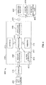
- FIG. 4 is a block diagram of an example system 400 for determining seatbelt status of a mass transit vehicle in accordance with the teachings disclosed herein.
- the example system 400 includes the sensor 216, the wireless communication module 218, a wireless receiver 402, a system interface 404, and the remote monitoring unit 406.
- the sensor 216 and the wireless communication module 218 of the illustrated example are disposed in the cavity 212 ( FIGS. 2A-3 ) of the seatbelt 200 ( FIGS. 2A-3 ) (e.g., disposed in the recess 308 of FIG. 3 ), and the wireless receiver 402, the system interface 404, and the remote monitoring unit 406 are located in a remote location of the mass transit vehicle (e.g., the aircraft 100 of FIG. 1 ).
- the sensor 216 detects if the tongue 204 of the seatbelt 200 is in the secured position and sends (e.g., via the wiring 310 of FIG. 3 ) a signal to the wireless communication module 218 indicating whether the tongue 204 is in the secured or fastened position or the unsecured or unfastened position.
- the wireless communication module 218 includes a sensor interface 408, a processor 410, an electrically erasable programmable read-only memory (EEPROM) 412, an alarm indicator 414, memory 416, and a wireless transceiver 418.
- the wireless communication module 218 is powered, for example, via a battery disposed in the cavity 212 of the buckle 202.
- the sensor interface 408 receives signals sent from the sensor 216 that indicate the position of the tongue 204. Additionally or alternatively, the sensor interface 408 receives signals from other sensors (e.g., sensors 606, 608 of FIGS. 6A-7 ) of the seatbelt 200 to determine the status of the seatbelt 200.
- the sensor interface 408 converts the received signals into a form compatible with the processor 410, and sends the converted signals to the processor 410.
- the processor 410 of the illustrated example is hardware.
- the processor 410 can be implemented by one or more integrated circuits, logic circuits, microprocessors or controllers from any desired family or manufacturer.
- the processor 410 includes a local memory (e.g., a cache).
- the processor 410 of the illustrated example determines a status of the seatbelt 200 based on the signals received from the sensor interface 408. For example, if the signals indicate that the tongue 204 is in the secured position, the processor 410 determines that the seatbelt 200 is in the fastened position. In contrast, if the signals indicate that the tongue 204 is not in the secured position, the processor 410 determines that the seatbelt 200 is in the unfastened position.
- the EEPROM 412 of the illustrated example stores data when power is removed from the wireless communication module 218.
- the EEPROM 412 provides a non-volatile memory that stores a model type, a serial number and/or communication protocols of the wireless communication module 218.
- the processor 410 sends an alarm signal to the alarm indicator 414 if the processor 410 determines that the seatbelt 200 is in the unfastened position.
- the alarm indicator 414 includes an audio unit 417 adjacent the seatbelt 200 and/or the corresponding seat that emits an audio alarm if processor 410 sends a signal that the seatbelt 200 is unfastened.
- the alarm indicator 414 includes a display unit 415 adjacent the seatbelt 200 and/or the corresponding seat that provides a visual indication if the seatbelt 200 is unfastened.
- the wireless communication module 218 receives data (e.g., from the remote monitoring unit 406) that indicates whether the seat corresponding to the seatbelt 200 is occupied.
- the processor 410 sends an alarm signal to the alarm indicator 414 if the processor 410 determines that the seatbelt 200 is in the unfastened position and the corresponding seat is occupied. If the seat is unoccupied, the processor 410 does not send to the alarm signal to the alarm indicator 414.
- the audio unit 417 and/or the display unit 415 adjacent the seatbelt 200 and/or the corresponding seat do not indicate that the seatbelt 200 is unfastened if the corresponding seat is unoccupied.
- the memory 416 of the illustrated example logs a status history of the seatbelt 200 that includes times and/or durations associated with the status of the seatbelt 200. For example, the memory 416 logs a time when the seatbelt 200 becomes unfastened, a duration that the seatbelt 200 remains unfastened, a time when the seatbelt 200 becomes fastened, a duration that the seatbelt remains fastened, etc.
- the example memory 416 includes volatile memory and/or non-volatile memory.
- Example volatile memory may be implemented by Synchronous Dynamic Random Access Memory (SDRAM), Dynamic Random Access Memory (DRAM), RAMBUS Dynamic Random Access Memory (RDRAM) and/or any other type of random access memory device.
- Example non-volatile memory may be implemented by flash memory and/or any other desired type of memory device. Access to the memory 416 is controlled, for example, by a memory controller. In some examples, the memory 416 of FIG.
- tangible computer readable storage medium such as a flash memory, a read-only memory (ROM), a cache, a random-access memory (RAM) and/or any other storage device or storage disk in which information is stored for any duration (e.g., for extended time periods, permanently, for brief instances, for temporarily buffering, and/or for caching of the information).
- tangible computer readable storage medium is expressly defined to include any type of computer readable storage device and/or storage disk and to exclude propagating signals and transmission media.
- tangible computer readable storage medium and “tangible machine readable storage medium” are used interchangeably.
- non-transitory computer and/or machine readable medium such as a flash memory, a read-only memory, a cache, a random-access memory and/or any other storage device or storage disk in which information is stored for any duration (e.g., for extended time periods, permanently, for brief instances, for temporarily buffering, and/or for caching of the information).
- non-transitory computer readable medium is expressly defined to include any type of computer readable storage device and/or storage disk and to exclude propagating signals and transmission media.
- the wireless communication module 218 includes the wireless transceiver 418.
- the wireless transceiver 418 sends data from the wireless communication module 218 to the wireless receiver 402 that is located at a remote location of the mass transit vehicle.
- the wireless transceiver 418 sends the current status of the seatbelt 200, the model type, serial number and/or communication protocols of the wireless communication module 218, and/or the status history of the seatbelt 200 to the wireless receiver 402 of the mass transit vehicle.
- the system interface 404 of the illustrated example is communicatively coupled to wireless receiver 402 and the remote monitoring unit 406.
- the system interface 404 receives the data sent from the wireless transceiver 418 of the wireless communication module 218 and converts the received data into a form compatible with the remote monitoring unit 406.
- the system interface 404 and/or the wireless receiver 402 are integral to the remote monitoring unit 406.
- the remote monitoring unit 406 of the illustrated example is in a remote location of the mass transit vehicle relative to the seats of the mass transit vehicle.
- the remote monitoring unit 406 may be located in a crew area (e.g., a crew area 507 of FIG. 5 ) and/or a flight deck (e.g., a flight deck 501 of FIG. 5 ) of the mass transit vehicle.
- the remote monitoring unit 406 indicates the status of the seatbelt 200 to enable a crew member of the mass transit vehicle (e.g., an attendant, a pilot, etc.) to identify whether the seatbelt is unfastened without having to enter a passenger compartment (e.g., the passenger compartment 110 of FIGS. 1 and 5 ) to visually inspect the seatbelt 200.
- the remote monitoring unit 406 provides a visual indication and/or emits an audio alarm if the seatbelt 200 is in the unfastened position.
- FIG. 5 is an example display 500 of the remote monitoring unit 406 that indicates status of seatbelts of the example aircraft 100.
- the example display 500 displays the flight deck 501, the crew areas 507, and the passenger compartment 110 of the aircraft 100.
- the passenger compartment 110 of the display 500 includes passenger seats 506.
- the seats 506 of the passenger compartment 110 include respective seatbelts to secure passengers in the seats 506 during travel.
- each of the seats 506 has a seatbelt (e.g., the seatbelts 200 of FIGS. 2-3 ) that includes a sensor and/or sensors (e.g., the sensor 216 of FIGS. 2-4 , the sensors 606, 608 of FIGS. 6A-7 ) to detect a status (e.g., fastened, unfastened, unoccupied) of the seatbelt and includes a wireless communication module (e.g., the wireless communication module 218 of FIGS. 2-4 ) to communicate the status of the seatbelt to the remote monitoring unit 406.
- a wireless communication module e.g., the wireless communication module 218 of FIGS. 2-4
- one of the seats 506 includes a wireless communication module (e.g., a first wireless communication module having a first transceiver) that sends a wireless signal 420 (e.g., a first wireless signal) to the remote monitoring unit 406, and another of the seats (e.g., a second seat) includes a wireless communication module (e.g., a second wireless communication module having a second transceiver) that sends a wireless signal 420 (e.g., a second wireless signal) to the remote monitoring unit 406.
- a flight manifest is entered into the remote monitoring unit 406 that indicates which of the seats 506 are occupied by a passenger for a flight.
- the example display 500 visually indicates which of the seats 506 of the passenger compartment are unoccupied, are occupied and correspond to a seatbelt in the fastened position, and/or are occupied and correspond to a seatbelt in the unfastened position.
- the seats 506 include a first seat 502 and a second seat 503 where the seats 502, 503 are implemented with respective seatbelts 504, 505 as disclosed herein.
- the first seat belt 504 and the second seatbelt 505 are implemented by the example seatbelt 200 FIG. 2 and/or the example seatbelt 600 of FIG. 6 .
- the display 500 indicates that seats 508 are occupied and have seatbelts in the fastened position.
- the seats 508 are represented by a "+" symbol.
- the seats 508 are identified in the display 500 by a first color (e.g., a green symbol such as a green circle, a green rectangle, a green seat, etc.).
- the example display 500 indicates that seats 510 are occupied and have seatbelts in the unfastened position.
- the seats 510 of FIG. 5 are represented by a "-" symbol.
- the seats 508 are identified in the display 500 by a second color (e.g., a red symbol such as a red circle, a red rectangle, a red seat, etc.).
- the example display 500 indicates that seats 512 are unoccupied.
- the unoccupied seats 512 do not include a symbol.
- the seats 512 are identified in the display 500 by a third color (e.g., a grey seat).
- the remote monitoring unit 406 emits an audio alarm if at least one of the occupied seatbelts is unfastened to alert a crew member of the example aircraft 100 that at least one of the passengers is not secured in a seat.
- the example remote monitoring unit 406 enables attendants and/or other crew members to continuously monitor status of the seatbelts of the aircraft from a single location without having to traverse through the passenger compartment 110 to visually inspect the seatbelts of the passengers.
- FIGS. 6A-6B illustrate another example seatbelt 600 of a mass transit vehicle in accordance with the teachings herein. More specifically, FIG. 6A is a perspective view of the example seatbelt 600, and FIG. 2B is a rear view of the example seatbelt 600. In the illustrated example, the seatbelt 600 is in a fastened position in which the tongue 204 is in the secured position (e.g., the tongue 204 is securely received by the buckle 202) to secure a passenger in a seat. As illustrated in FIGS.
- the example seatbelt 600 includes release latches 602, 604 that are in rest positions when the tongue 204 is securely received by the buckle 202 to maintain and/or secure the tongue 204 in the secured position and, thus, to maintain and/or secure the seatbelt 600 in the fastened position.
- the release latches 602, 604 are in the respective rest positions to engage and/or are positioned adjacent the tongue 204 to deter, impede and/or prevent the tongue 204 from decoupling from the buckle 202.
- the passenger pushes the release button 214 and the release latches 602, 604 to their respective release positions and removes the tongue 204 from the cavity 212 of the buckle 202.
- the release latches 602, 604 enhance the safety provided by the seatbelt 600 by maintaining the seatbelt 600 in the fastened position if the release button 214 is accidently pushed by the passenger.
- the example seatbelt 200 includes the sensor 216, sensors 606, 608, and the wireless communication module 218 disposed in the cavity 212 of the buckle 202.
- the sensor 216 detects whether the tongue 204 is in the secured position
- the sensor 606 detects whether the release latch 602 is in the release position
- the sensor 608 detects whether the release latch 604 is in the release position.
- the sensors 216, 606, 608 are in communication (e.g., electronic communication, wired communication, etc.) with the wireless communication module 218.
- the wireless communication module 218 of the illustrated example determines a status of the seatbelt 600 (e.g., whether the seatbelt 600 is in the fastened position or the unfastened position) based on the sensors 216, 606, 608. For example, the wireless communication module 218 determines that the seatbelt 600 is in the fastened position if the sensor 216 detects that the tongue 204 is in the secured position, the sensor 606 detects that the release latch 602 is in the rest position, and the sensor 608 detects that the release latch 604 is in the rest position.
- the example wireless communication module 218 determines that the seatbelt 600 is in the unfastened position if the sensor 216 detects that the tongue 204 is not in the secured position, the sensor 606 detects that the release latch 602 is in the release position, and/or the sensor 608 detects that the release latch 604 is in the release position. Further, the example wireless communication module 218 wirelessly communicates the status of the seatbelt 200 to a remote location (e.g., the remote monitoring unit 406 of FIG. 4 ) of the mass transit vehicle (e.g., the aircraft 100 of FIG. 1 ). In other examples, the remote monitoring unit 406 that is in communication with the wireless communication module 218 determines the status of the seatbelt 600 based on the sensors 216, 606, 608.
- FIG. 7 depicts the cavity 212 of the buckle 202 of the example seatbelt 600 in the fastened position.
- the female end 304 is coupled to the wall 306 that defines the recess 308 in the cavity 212 of the buckle 202.
- the recess 308 defined by the wall 306 contains the wireless communication module 218 ( FIG. 2 ), a battery to power the wireless communication module 218 and/or other electrical components disposed in the cavity 212 of the buckle 202.
- the recess 308 of the illustrated example contains the wiring 310 that couples the sensor 216 ( FIG. 6B ) to the wireless communication module 218, wiring 702 that couples the sensor 606 to the wireless communication module 218, and wiring 704 that couples the sensor 608 to the wireless communication module 218.
- the sensor 216 detects whether the male end 302 of the tongue 204 is received by the female end 304 of the buckle 202, the sensor 606 detects whether the release latch 602 is in the rest position, and the sensor 608 detects whether the release latch 604 is in the rest position.
- the sensors 216, 606, 608 send signals to the wireless communication module 218 that enables the wireless communication module 218 (or another device such as the remote monitoring unit 406 of FIG. 4 ) to determine whether the seatbelt 200 is in the fastened position or the unfastened position.
- the male end 302 of the tongue 204 and the release latches 602, 604 are composed of steel and/or another metallic material, and the sensors 216, 606, 608 are micro-reed relays, reed switches, Hall-effect sensors, and/or other magnetically-responsive switches.
- the wall 306 of the illustrated example defines apertures through which the corresponding sensors 606, 608 extend.
- the apertures enable the sensors 606, 608 to be positioned proximate to the corresponding release latches 602, 604 when the release latches 602, 604 are in the rest positions so that the sensors 606, 608 are able to detect the magnetic fields that are affected by the corresponding release latches 602, 604 without interference from the wall 306.
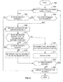
- FIG. 8 is a flowchart representative of an example method 800 to determine status of seatbelts of a mass transit vehicle.
- the example method 800 is described with reference to the flowchart illustrated in FIG. 8 , many other methods of determining status of seatbelts of a mass transit vehicle may alternatively be used.
- the order of execution of the blocks may be changed, and/or some of the blocks described changed, eliminated, and/or combined.
- the example method 800 for determining status of seatbelts of a mass transit vehicle is discussed in connection with the example seatbelt 200 of FIGS. 2A-3 , the example system 400 of FIG. 4 , the example display 500 of FIG. 5 and/or the example seatbelt 600 of FIGS. 6A-7 .
- the example method 800 may use the example seatbelt 200 of FIGS. 2A-3 , the example system 400 of FIG. 4 , the example display 500 of FIG. 5 and/or the example seatbelt 600 of FIGS. 6A-7 to determine status of seatbelts of a mass transit vehicle, components identified in FIGS. 2A-7 having functions substantially similar or identical to the functions of components described below will not be described in detail again. Instead, the same reference numbers will be used for like structures.
- the example method 800 disclosed herein starts by identifying a seatbelt of a mass transit vehicle (block 802).
- the remote monitoring unit 406 ( FIG. 4 ) identifies the seatbelt 200 ( FIGS. 2A-3 ) or the seatbelt 600 ( FIGS. 6A-7 ) of the aircraft 100 ( FIGS. 1 and 5 ).
- the example method 800 determines whether the seat (e.g., one of the seats 506 of FIG. 5 ) corresponding to the identified seatbelt (e.g., the seatbelt 200, the seatbelt 600) is occupied.
- the remote monitoring unit 406 determines if the seat 506 is occupied based on the flight manifest.
- the remote monitoring unit 406 determines if there is another seatbelt (e.g., the seatbelt 200, the seatbelt 600) (block 806). If there is another seatbelt, blocks 802, 804 are repeated.
- another seatbelt e.g., the seatbelt 200, the seatbelt 600
- the example method 800 identifies a sensor (e.g., the sensor 216 of FIGS. 2B , 3 , 6B , and 7 ) of the identified seatbelt (e.g., the seatbelt 200, the seatbelt 600) that corresponds to an occupied seat 506 (block 808).
- the wireless communication module 218 ( FIGS. 2B , 4 , and 6B ) of the seatbelt and/or the remote monitoring unit 406 identifies the sensor 216 of the seatbelt.
- the wireless communication module 218 of the seatbelt and/or the remote monitoring unit 406 determines whether the sensor 216 indicates that the seatbelt is in a fastened position.
- the sensor 216 indicates that the seatbelt is in the fastened position if the sensor 216 detects that the tongue 204 (e.g., FIGS. 2A-3 and 6A-7 ) of the seatbelt is received by the buckle 202 (e.g., FIGS. 2A-3 and 6A-7 ) of the seatbelt and indicates that the seatbelt is not in the fastened position if the sensor 216 detects that the tongue 204 is not received by the buckle 202.
- the sensor 216 indicates that the seatbelt is in the fastened position if the sensor 216 detects that the tongue 204 (e.g., FIGS. 2A-3 and 6A-7 ) of the seatbelt and indicates that the seatbelt is not in the fastened position if the sensor 216 detects that the tongue 204 is not received by the buckle 202.
- the wireless communication module 218 of the seatbelt and/or the remote monitoring unit 406 determines that the seatbelt is in the unfastened position (block 812).
- the example method optionally emits an alarm indicating that the seatbelt is unfastened.
- the remote monitoring unit 406 and/or an audio unit 417 adjacent the seat 506 emits an audio alarm to alert a passenger and/or a crew member of the mass transit vehicle 100 that the seatbelt of the occupied seat 506 is unfastened.
- a first audio unit 518 is positioned adjacent the first seat 502 and a second audio unit 520 is positioned adjacent the second seat 503.
- the first and second audio units 518, 520 may be implemented by the display unit 415 of the alarm audio unit 417.
- the wireless communication module 218 of the seatbelt and/or the remote monitoring unit 406 determines if there is another sensor of the identified seatbelt (block 816). If there is another sensor of the identified seatbelt, blocks 808, 810 are repeated. For example, the method 800 repeats blocks 808, 810 to identify and determine whether the sensors 606, 608 ( FIGS. 6B-7 ) that detect positions of the corresponding release latches 602, 604 ( FIGS. 6A-7 ) indicate that the seatbelt is in the fastened position.
- the sensors 606, 608 associated with the release latches 602, 604 indicate that the seatbelt is in the fastened position if the sensors 606, 608 detect that the corresponding release latches 602, 604 are in the rest positions and indicate that the seatbelt is not in the fastened position if the sensors 606, 608 detect that the corresponding release latches 602, 604 are in the release position. If, at block 816, the wireless communication module 218 of the seatbelt and/or the remote monitoring unit 406 identifies that there are no other sensors of the identified seatbelt, the wireless communication module 218 of the seatbelt and/or the remote monitoring unit 406 determines that the identified seatbelt is in the fastened position (block 818).
- the remote monitoring unit 406 determines if there is another seatbelt (e.g., the seatbelt 200 of FIGS. 2A-3 , the seatbelt 600 of FIGS. 6A-7 ) of the mass transit vehicle 100 (block 820). If the remote monitoring unit 406 determines that there is another seatbelt of the mass transit vehicle 100, the example method 800 repeats blocks 802, 804, 806, 808, 810, 812, 814, 816, 818.
- another seatbelt e.g., the seatbelt 200 of FIGS. 2A-3 , the seatbelt 600 of FIGS. 6A-7
- the example method displays status of the identified seatbelt(s) 506 (block 822).
- the display 500 e.g., FIG. 5
- the display 500 indicates the seats that are occupied and have fastened seatbelts (e.g., the seats 508 of FIG. 5 ), the seats that are occupied and have fastened seatbelts (e.g., the seats 510 of FIG. 5 ), and/or the seats that are unoccupied (e.g., the seats 512 of FIG. 5 ).
- display units 415 adjacent respective seats 506 of the mass transit vehicle 100 indicate whether the seatbelt of the corresponding seat is unoccupied, occupied with a fastened seatbelt, and/or occupied with an unfastened seatbelt.
- a first display unit 514 is positioned adjacent the first seat 502 and a second display unit 516 is positioned adjacent the second seat 503.
- the first and second display units 514, 516 may be implemented by the display unit 415 of the alarm indicator 414.
Landscapes
- Engineering & Computer Science (AREA)
- Automation & Control Theory (AREA)
- Mechanical Engineering (AREA)
- Aviation & Aerospace Engineering (AREA)
- Automotive Seat Belt Assembly (AREA)
Abstract
Description
- This patent relates generally to seatbelts and, more particularly, to methods and apparatus for determining seatbelt status.
- Mass transit vehicles (e.g., aircraft, buses, trains, ferries, etc.) often include seatbelts. The seatbelts of mass transit vehicles are used to secure passengers in seats to reduce a likelihood of the passengers being ejected from their seats if the mass transit vehicle is involved in a collision, turbulence and/or a sudden stop. In some instances, the passengers may fail to fasten the seatbelts to secure themselves in the seats, thereby increasing a likelihood of the passengers being ejected from their seats. To increase use of the seatbelts (i.e., compliance) by the passengers, attendants (e.g., passenger attendants, flight attendants, train attendants, etc.) visually inspect whether the passengers have fastened in the seatbelts.
- In one example, a seatbelt system for a mass transit vehicle includes a first seatbelt of a first seat that includes a first buckle defining a first cavity to receive a first tongue in a fastened position and a first magnetically-responsive switch disposed in the first cavity to detect the first tongue when the first seatbelt is in the fastened position. The example system includes a second seatbelt of a second seat that includes a second buckle defining a second cavity to receive a second tongue in the fastened position and a second magnetically-responsive switch disposed in the second cavity to detect the second tongue when the second seatbelt is in the fastened position. The example system includes a remote monitoring unit to indicate, when the first seat is occupied, if the first seatbelt is in the fastened positioned or an unfastened position. The remote monitoring unit is to indicate, when the second seat is occupied, if the second seatbelt is in the fastened positioned or the unfastened position.
- In another example, a method for monitoring seatbelts in a mass transit vehicle includes detecting, via a first magnetically-responsive switch, if a first seatbelt of a first seat is in a fastened position or an unfastened position. The first magnetically-responsive switch is disposed in a first buckle of the first seatbelt to detect a first tongue when the first seatbelt is in the fastened position. The example method includes detecting, via a second magnetically-responsive switch, if a second seatbelt of a second seat is in the fastened position or the unfastened position. The second magnetically-responsive switch is disposed in a second buckle of the second seatbelt to detect a second tongue when the second seatbelt is in the fastened position. The example method includes communicating a status of the first seatbelt and a status of the second seatbelt to a remote monitoring unit. The example method includes displaying, via the remote monitoring unit, the status of the first seatbelt when the first seat is occupied and the status of the second seatbelt when the second seat is occupied.
- In another example, a mass transit vehicle system includes first means for detecting when a first seatbelt of a first seat is in a fastened position. The first means for detecting is disposed in a first buckle of the first seatbelt to detect a first tongue when the first seatbelt is in the fastened position. The example system includes second means for detecting when a second seatbelt of a first seat is in the fastened position. The second means for detecting is disposed in a second buckle of the second seatbelt to detect a second tongue when the second seatbelt is in the fastened position. The example system includes means for communicating a status of the first seatbelt and a status of the second seatbelt. The example system includes means for displaying to indicate the status of the first seatbelt when the first seat is occupied and to display the status of the second seatbelt when the second seat is occupied.
-
-
FIG. 1 depicts an example aircraft in accordance with the teachings disclosed herein. -
FIG. 2A is a perspective view of an example seatbelt constructed in accordance with the teachings disclosed herein. -
FIG. 2B is a rear view of the example seatbelt ofFIG. 2A . -
FIG. 3 depicts a cavity of a buckle of the example seatbelt ofFIGS. 2A-2B in a fastened position. -
FIG. 4 is a block diagram of an example system for determining a seatbelt status in accordance with the teachings disclosed herein. -
FIG. 5 is an example display of an example remote monitoring unit of the example system ofFIG. 4 . -
FIG. 6A is a perspective view of another example seatbelt constructed in accordance with the teachings disclosed herein. -
FIG. 6B is a rear view of the example seatbelt ofFIG. 6A . -
FIG. 7 depicts a cavity of a buckle of the example seatbelt ofFIGS. 6A-6B in a fastened position. -
FIG. 8 is a flowchart representative of an example method to implement the example system ofFIG. 4 to determine a status of the example seatbelt ofFIGS. 2A-3 and/or the example seatbelt ofFIGS. 6A-7 in accordance with the teachings herein. - The figures are not to scale. Instead, to clarify multiple layers and regions, the thicknesses of the layers may be enlarged in the drawings. Wherever possible, the same reference numbers will be used throughout the drawing(s) and accompanying written description to refer to the same or like parts.
- Many known mass transit vehicles (e.g., aircraft, buses, trains, ferries, etc.) include seatbelts to secure passengers in seats of the mass transit vehicles. For example, seatbelts secure passengers in seats of mass transit vehicles to prevent the passengers from being ejected from the seats upon a collision, turbulence and/or a sudden stop.
- Some known seatbelts include a tongue and a buckle in which the buckle receives and holds the tongue to fasten the seatbelt. The buckle of some known seatbelts is coupled to one or more straps, and the tongue of such known seatbelts is coupled to one or more straps. To secure the passenger in a seat, the straps of the tongue and/or the buckle extend over a portion (e.g., a waist, a torso, a chest, etc.) of the passenger, and the tongue of the seatbelt is fastenably received by the buckle of the seatbelt.
- In some instances, passengers of known mass transit vehicles may not fasten the seatbelt to secure themselves in the corresponding seats, thereby increasing the likelihood that such passengers are ejected from their seats if the mass transit vehicle is involved in a collision, turbulence and/or an abrupt change in velocity. For example, some passengers may forget to fasten their seatbelts upon sitting in their seats or choose not to fasten their seatbelts. Crew members (e.g., flight attendants, train attendants, rail attendants, etc.) may traverse through passenger compartments of the mass transit vehicles to visually inspect whether the passengers have securely fastened their seatbelts. The passengers may unfasten their seatbelts following the attendant's inspection.
- The example methods, systems, and apparatus disclosed herein facilitate identification of unfastened seatbelts of occupied seats of a mass transit vehicle by crew members and/or passengers of the mass transit vehicle to increase use of the seatbelts and, thus, to reduce the likelihood of the passengers of the mass transit vehicle of from being ejected from their seats. Additionally, notice may be provided to alert crew to an unbuckled passenger seatbelt and the need traverse through passenger compartments to visually inspect passenger seatbelts may be reduced. An example seatbelt system disclosed herein includes a first seatbelt of a first seat and a second seatbelt of a second seat of a mass transit vehicle. The first seatbelt includes a first buckle that defines a first cavity to receive a first tongue in a fastened position and a first magnetically-responsive switch disposed in the first cavity to detect the first tongue when the first seatbelt is in the fastened position. The second seatbelt includes a second buckle that defines a second cavity to receive a second tongue in the fastened position and a second magnetically-responsive switch disposed in the second cavity to detect the second tongue when the second seatbelt is in the fastened position. Further, the example seatbelt system includes a remote monitoring unit. When the first seat is occupied by a passenger, the remote monitoring unit indicates if the seatbelt is in the fastened position or an unfastened position. Similarly, when the second seat is occupied by a passenger, the remote monitoring unit indicates if the seatbelt is in the fastened position or in the unfastened position.
- The first and second tongues of the respective first and second seatbelts may be composed of metallic material so that the first and second magnetically-responsive switches can detect the first and second tongues in the respective fastened positions. The first and second magnetically-responsive switches may be micro-reed relays, reed switches, or Hall-effect sensors that detect the first and second tongues of the respective first and second seatbelts. The example seatbelts having the magnetically-responsive switches may be incorporated in mass transit vehicles, such as aircraft, buses, trains, ferries, etc., to enables the passengers, pilots and/or attendants of the mass transit vehicles to identify occupied seats for which the corresponding seatbelts are unfastened. Additionally or alternatively, the magnetically-responsive switches of the example seatbelts can be incorporated in other vehicles such as personal vehicles (e.g., cars, trucks, boats, etc.), tractor units (e.g., tractor-trailers, agricultural tractors, etc.) racing vehicles, roller coasters, etc.
- Seatbelts disclosed herein include a release button that is to be maintained in a release position by a passenger to enable the tongue to be removed from the buckle to transition the seatbelt from a fastened position to an unfastened position. Additionally or alternatively, some example seatbelts disclosed herein include release latches (e.g., a first release latch, a second release latch) that are to be moved to respective release positions by the passenger to enable the tongue to be removed from buckle to transition the seatbelt from the fastened position to the unfastened position. For example, a release latch moves from a rest position to a release position to enable the tongue of the seatbelt to transition from the fastened position to the unfastened position. Such disclosed seatbelts require the release button and the release latches to be in the respective release positions to enable the tongue of the seatbelt to be removed from the buckle of the seatbelt. Thus, the release latches enhance the safety provided by such seatbelts by maintaining the seatbelts in the fastened position if the release button is accidently engaged and enabling the tongue to be released from the buckle only when both the release button and the side release latches are engaged purposefully by the passenger.
- The seatbelts may optionally include magnetically-responsive switches (e.g., a third magnetically-responsive switch, a fourth magnetically-responsive switch, etc.) to detect when the release latches are in the respective rest positions. In such examples, the magnetically-responsive switches identify that the seatbelt is in the unfastened position if the magnetically-responsive switches detect that one of the release latches is in the release position and/or that the tongue of the seatbelt is not received by the buckle. As a result, the magnetically-responsive switches increase the safety provided by the example seatbelts by identifying which of the seatbelts are in the unfastened position and, thus, identifying which of the passengers are not compliant and secured in their seats.
- Seatbelts disclosed herein include a wireless transceiver (e.g., a Bluetooth module) to wirelessly transmit a status of the corresponding seatbelt to the remote monitoring unit of the mass transit vehicle. For example, a first wireless transceiver coupled to and/or disposed in the first buckle of the first seatbelt is to wirelessly transmit a status of the of the first seatbelt to a wireless receiver of the remote monitoring unit, and a second wireless transceiver coupled to and/or disposed in the second buckle of the second seatbelt is to wirelessly transmit a status of the of the second seatbelt to the wireless receiver of the remote monitoring unit. By utilizing wireless communication between the seatbelts and the remote monitoring unit, the examples disclosed herein reduce an amount of electrical wiring throughout the mass transit vehicle, thereby reducing an amount of weight, cost, and complexity added to the mass transit vehicle. In some examples, the remote monitoring unit and/or a communication module (e.g., a wireless communication module, a Bluetooth module, etc.) of a seatbelt (e.g., the first seatbelt, the second seatbelt) logs a status history (e.g., a first status history, a second status history) of the seatbelt. For example, the status history logged by the remote monitoring unit and/or the communication module provides information about whether a passenger was secured in his or her seat during a particular event (e.g., a collision) that occurred on the mass transit vehicle.
- The example remote monitoring units disclosed herein enable crew members (e.g., pilots, flight attendants, train attendants, rail attendants, etc.) of a mass transit vehicle (e.g., an aircraft, a bus, a train, a ferry, etc.) to identify from a single location (e.g., a flight deck, crew area, closet, etc.), which may or may not have direct line of sight, the passengers of the mass transit vehicle that are not secured in their seats by their seatbelts. Example remote monitoring units display which of the seats of the mass transit vehicle are unoccupied, are occupied and include a seatbelt in a fastened position, and are occupied and include a seatbelt in an unfastened position. In some examples, the remote monitoring unit emits an audio alarm to notify an attendant that a seatbelt for at least one occupied seat of the mass transit vehicle is in an unfastened position. As a result, the example remote monitoring units enable crew members to continuously monitor status of the seatbelts of the mass transit vehicle from a single, convenient location, and optionally may be done without visual inspection by an attendant.
- The systems disclosed herein may optionally include display units (e.g., a first display unit, a second display unit) adjacent corresponding seats (e.g., the first seat, the second seat) of the mass transit vehicle that indicate status of the seats and/or the corresponding seatbelts (e.g., the first seatbelt, the second seatbelt). The systems disclosed herein may also optionally include audio units (e.g., a first audio unit, a second audio unit) adjacent corresponding seats to emit an audio alarm (e.g., a first audio alarm, a second audio alarm) if the corresponding seat is occupied and the corresponding seatbelts are unfastened. The example display units and audio units adjacent the seats provide passengers of the seats with a warning that their seatbelts are unfastened to increase use of the seatbelts (i.e., compliance) by the passengers.
- Turning to the figures,
FIG. 1 illustrates anexample aircraft 100 including wings 102 (e.g., a right wing and a left wing) extending laterally outward from afuselage 104. Each of thewings 102 of the illustrated example supports anaircraft engine 106 via apylon 108. Apassenger compartment 110 is disposed within thefuselage 104 of the illustrated example. -
FIGS. 2A-2B illustrate anexample seatbelt 200 of a mass transit vehicle (e.g., theaircraft 100 ofFIG. 1 ) in accordance with the teachings herein. More specifically,FIG. 2A is a perspective view of theexample seatbelt 200, andFIG. 2B is a rear view of theexample seatbelt 200. Theexample seatbelt 200 includes abuckle 202 and atongue 204 coupled to ahandle 206. Thebuckle 202 defines an aperture 208 (e.g., a first aperture) through which a belt (e.g., a first belt, a first strap, first webbing, etc.) extends to couple to thebuckle 202, and thehandle 206 defines an aperture 210 (e.g., a second aperture) through which another belt (e.g., a second belt, a second strap, second webbing, etc.) extends to couple to thehandle 206. In the illustrated example, thebuckle 202, thetongue 204, and thehandle 206 of theseatbelt 200 are composed of steel and/or another high strength material that enables theseatbelt 200 to withstand large forces. - In the illustrated example of
FIGS. 2A-2B , theseatbelt 200 is in a fastened position in which thetongue 204 is securely received by thebuckle 202 to secure a passenger in a seat. For example, in the fastened position, thetongue 204 is inserted into and securely fastened within an opening orcavity 212 of thebuckle 202. To transition theexample seatbelt 200 from the fastened position to an unfastened position in which thetongue 204 is not securely received by thebuckle 202, the passenger engages arelease button 214 and removes thetongue 204 from thecavity 212 of thebuckle 202. For example, to unfasten theseatbelt 200, the passenger presses therelease button 214 to a release position, maintains therelease button 214 in the release position, and removes thetongue 204 from thecavity 212 of thebuckle 202 by pulling thehandle 206 in a direction away from thecavity 212. - As illustrated in
FIG. 2B , theexample seatbelt 200 includes asensor 216 and awireless communication module 218 disposed in thecavity 212 of thebuckle 202. Thesensor 216 of the illustrated example identifies a status of theseatbelt 200 by detecting when thetongue 204 is in a secured position (e.g., by detecting when thetongue 204 is securely received by the buckle 202). For example, thesensor 216 identifies that theseatbelt 200 is in the fastened position by detecting that thetongue 204 is in the secured position and identifies that theseatbelt 200 is in the unfastened position by detecting that thetongue 204 is not in the secured position. - In the illustrated example, the
sensor 216 is in communication (e.g., electronic communication, wired communication, etc.) with thewireless communication module 218. Thewireless communication module 218 of the illustrated example wirelessly communicates the status of the seatbelt 200 (e.g., the fastened position, the unfastened position) to a remote location. For example, thewireless communication module 218 wirelessly communicates the status of theseatbelt 200 to a remote monitoring unit (e.g., aremote monitoring unit 406 ofFIG. 4 ) of the mass transit vehicle. - In the illustrated example, the
wireless communication module 218 is a Bluetooth module. As illustrated inFIG. 2A , asurface 220 of thebuckle 202 of theexample seatbelt 200 defines awindow 222 adjacent thewireless communication module 218 that enables thewireless communication module 218 to communicate the status of theseatbelt 200 to the remote location. For example, thewindow 222 of thebuckle 202 enables a signal (e.g., a wireless signal) of thewireless communication module 218 to be sent from within thecavity 212 enclosed by the material of thebuckle 202 that would otherwise interfere with a signal transmitted by a Bluetooth module. Thewindow 222 ofFIG. 2A is covered by acover 224 composed of, for example, plastic and/or any other material that does not interfere with a signal of a Bluetooth module to enable the signal to be communicated from thecavity 212 of thebuckle 202. Further, thecover 224 prevents other objects from the entering thecavity 212 of thebuckle 202 and damaging components disposed in the cavity 212 (e.g., thesensor 216, the wireless communication module 218). In some examples in which thewireless communication module 218 is a Bluetooth module, thewireless communication module 218 is powered by a battery that is disposed in thecavity 212 of thebuckle 202. In some examples, the lifespan of the battery may be extended by causing thewireless communication module 218 to enter a sleep mode when thewireless communication module 218 is not communicating data. -
FIG. 3 depicts thecavity 212 of thebuckle 202 of theexample seatbelt 200 in the fastened position. As illustrated inFIG. 3 , thetongue 204 is securely fastened to thebuckle 202 when theseatbelt 200 is in the fastened position. For example, amale end 302 of thetongue 204 is securely received by afemale end 304 of thebuckle 202. As illustrated inFIG. 3 , thefemale end 304 is coupled to awall 306 that defines arecess 308 in thecavity 212 of thebuckle 202. For example, thefemale end 304 is integrally formed with thewall 306. Therecess 308 defined by thewall 306 contains the wireless communication module 218 (FIGS. 2A-2B ), a battery to power the wireless communication module 218 (FIGS. 2A-2B ) and/or other electrical components disposed in thecavity 212 of thebuckle 202. Therecess 308 of the illustrated containswiring 310 that is coupled to the sensor 216 (FIG. 2 ) and thewireless communication module 218 to communicatively couple thesensor 216 and thewireless communication module 218. - In the illustrated example, the
sensor 216 detects whether themale end 302 of thetongue 204 is received by thefemale end 304 of thebuckle 202 to determine the status of theseatbelt 200. For example, when thesensor 216 detects that themale end 302 is received by thefemale end 304, thesensor 216 sends, via thewiring 310, a signal to thewireless communication module 218 indicating that themale end 302 is in the secured position. In turn, thewireless communication module 218 determines that theseatbelt 200 is in the fastened position. When thesensor 216 detects that themale end 302 is not received by thefemale end 304, thesensor 216 sends, via thewiring 310, a signal to thewireless communication module 218 indicating that themale end 302 is not in the secured position. In turn, thewireless communication module 218 determines that theseatbelt 200 is in the unfastened position. - In the illustrated example, the
male end 302 of thetongue 204 is composed of steel and/or another metallic material, and thesensor 216 is a micro-reed relay, a reed switch, a Hall-effect sensor and/or any other magnetically-responsive switch that detects a change in a magnetic field that is affected by themale end 302 of thetongue 204. To enable thesensor 216 to detect the change in the magnetic field, thewall 306 and/or thefemale end 304 of the illustrated example define an aperture through which thesensor 216 extends. The aperture enables thesensor 216 to be positioned proximate to themale end 302 when themale end 302 is received by thefemale end 304 so that thesensor 216 is able to detect the change in the magnetic field (e.g., by preventing thewall 306 and/or thefemale end 304 from interfering with detection of the magnetic field) that is affected by themale end 302 of thetongue 204. -
FIG. 4 is a block diagram of anexample system 400 for determining seatbelt status of a mass transit vehicle in accordance with the teachings disclosed herein. Theexample system 400 includes thesensor 216, thewireless communication module 218, awireless receiver 402, asystem interface 404, and theremote monitoring unit 406. Thesensor 216 and thewireless communication module 218 of the illustrated example are disposed in the cavity 212 (FIGS. 2A-3 ) of the seatbelt 200 (FIGS. 2A-3 ) (e.g., disposed in therecess 308 ofFIG. 3 ), and thewireless receiver 402, thesystem interface 404, and theremote monitoring unit 406 are located in a remote location of the mass transit vehicle (e.g., theaircraft 100 ofFIG. 1 ). - In the illustrated example, the
sensor 216 detects if thetongue 204 of theseatbelt 200 is in the secured position and sends (e.g., via thewiring 310 ofFIG. 3 ) a signal to thewireless communication module 218 indicating whether thetongue 204 is in the secured or fastened position or the unsecured or unfastened position. - As illustrated in
FIG. 4 , thewireless communication module 218 includes asensor interface 408, aprocessor 410, an electrically erasable programmable read-only memory (EEPROM) 412, analarm indicator 414,memory 416, and awireless transceiver 418. Thewireless communication module 218 is powered, for example, via a battery disposed in thecavity 212 of thebuckle 202. In the illustrated example, thesensor interface 408 receives signals sent from thesensor 216 that indicate the position of thetongue 204. Additionally or alternatively, thesensor interface 408 receives signals from other sensors (e.g.,sensors FIGS. 6A-7 ) of theseatbelt 200 to determine the status of theseatbelt 200. Thesensor interface 408 converts the received signals into a form compatible with theprocessor 410, and sends the converted signals to theprocessor 410. - The
processor 410 of the illustrated example is hardware. For example, theprocessor 410 can be implemented by one or more integrated circuits, logic circuits, microprocessors or controllers from any desired family or manufacturer. In some examples, theprocessor 410 includes a local memory (e.g., a cache). Theprocessor 410 of the illustrated example determines a status of theseatbelt 200 based on the signals received from thesensor interface 408. For example, if the signals indicate that thetongue 204 is in the secured position, theprocessor 410 determines that theseatbelt 200 is in the fastened position. In contrast, if the signals indicate that thetongue 204 is not in the secured position, theprocessor 410 determines that theseatbelt 200 is in the unfastened position. - The
EEPROM 412 of the illustrated example stores data when power is removed from thewireless communication module 218. For example, theEEPROM 412 provides a non-volatile memory that stores a model type, a serial number and/or communication protocols of thewireless communication module 218. - In the illustrated example, the
processor 410 sends an alarm signal to thealarm indicator 414 if theprocessor 410 determines that theseatbelt 200 is in the unfastened position. For example, thealarm indicator 414 includes anaudio unit 417 adjacent theseatbelt 200 and/or the corresponding seat that emits an audio alarm ifprocessor 410 sends a signal that theseatbelt 200 is unfastened. Additionally or alternatively, thealarm indicator 414 includes adisplay unit 415 adjacent theseatbelt 200 and/or the corresponding seat that provides a visual indication if theseatbelt 200 is unfastened. - In some examples, the wireless communication module 218 (e.g., the wireless transceiver 418) receives data (e.g., from the remote monitoring unit 406) that indicates whether the seat corresponding to the
seatbelt 200 is occupied. In such examples, theprocessor 410 sends an alarm signal to thealarm indicator 414 if theprocessor 410 determines that theseatbelt 200 is in the unfastened position and the corresponding seat is occupied. If the seat is unoccupied, theprocessor 410 does not send to the alarm signal to thealarm indicator 414. As a result, theaudio unit 417 and/or thedisplay unit 415 adjacent theseatbelt 200 and/or the corresponding seat do not indicate that theseatbelt 200 is unfastened if the corresponding seat is unoccupied. - The
memory 416 of the illustrated example logs a status history of theseatbelt 200 that includes times and/or durations associated with the status of theseatbelt 200. For example, thememory 416 logs a time when theseatbelt 200 becomes unfastened, a duration that theseatbelt 200 remains unfastened, a time when theseatbelt 200 becomes fastened, a duration that the seatbelt remains fastened, etc. - The
example memory 416 includes volatile memory and/or non-volatile memory. Example volatile memory may be implemented by Synchronous Dynamic Random Access Memory (SDRAM), Dynamic Random Access Memory (DRAM), RAMBUS Dynamic Random Access Memory (RDRAM) and/or any other type of random access memory device. Example non-volatile memory may be implemented by flash memory and/or any other desired type of memory device. Access to thememory 416 is controlled, for example, by a memory controller. In some examples, thememory 416 ofFIG. 4 is a tangible computer readable storage medium such as a flash memory, a read-only memory (ROM), a cache, a random-access memory (RAM) and/or any other storage device or storage disk in which information is stored for any duration (e.g., for extended time periods, permanently, for brief instances, for temporarily buffering, and/or for caching of the information). As used herein, the term tangible computer readable storage medium is expressly defined to include any type of computer readable storage device and/or storage disk and to exclude propagating signals and transmission media. As used herein, "tangible computer readable storage medium" and "tangible machine readable storage medium" are used interchangeably. In some examples, thememory 416 ofFIG. 4 is a non-transitory computer and/or machine readable medium such as a flash memory, a read-only memory, a cache, a random-access memory and/or any other storage device or storage disk in which information is stored for any duration (e.g., for extended time periods, permanently, for brief instances, for temporarily buffering, and/or for caching of the information). As used herein, the term non-transitory computer readable medium is expressly defined to include any type of computer readable storage device and/or storage disk and to exclude propagating signals and transmission media. - As illustrated in
FIG. 4 , thewireless communication module 218 includes thewireless transceiver 418. In the illustrated example, thewireless transceiver 418 sends data from thewireless communication module 218 to thewireless receiver 402 that is located at a remote location of the mass transit vehicle. For example, thewireless transceiver 418 sends the current status of theseatbelt 200, the model type, serial number and/or communication protocols of thewireless communication module 218, and/or the status history of theseatbelt 200 to thewireless receiver 402 of the mass transit vehicle. - The
system interface 404 of the illustrated example is communicatively coupled towireless receiver 402 and theremote monitoring unit 406. Thesystem interface 404 receives the data sent from thewireless transceiver 418 of thewireless communication module 218 and converts the received data into a form compatible with theremote monitoring unit 406. In some examples, thesystem interface 404 and/or thewireless receiver 402 are integral to theremote monitoring unit 406. - The
remote monitoring unit 406 of the illustrated example is in a remote location of the mass transit vehicle relative to the seats of the mass transit vehicle. For example, theremote monitoring unit 406 may be located in a crew area (e.g., acrew area 507 ofFIG. 5 ) and/or a flight deck (e.g., aflight deck 501 ofFIG. 5 ) of the mass transit vehicle. Theremote monitoring unit 406 indicates the status of theseatbelt 200 to enable a crew member of the mass transit vehicle (e.g., an attendant, a pilot, etc.) to identify whether the seatbelt is unfastened without having to enter a passenger compartment (e.g., thepassenger compartment 110 ofFIGS. 1 and5 ) to visually inspect theseatbelt 200. For example, theremote monitoring unit 406 provides a visual indication and/or emits an audio alarm if theseatbelt 200 is in the unfastened position. -
FIG. 5 is anexample display 500 of theremote monitoring unit 406 that indicates status of seatbelts of theexample aircraft 100. Theexample display 500 displays theflight deck 501, thecrew areas 507, and thepassenger compartment 110 of theaircraft 100. As illustrated inFIG. 5 , thepassenger compartment 110 of thedisplay 500 includes passenger seats 506. - The
seats 506 of thepassenger compartment 110 include respective seatbelts to secure passengers in theseats 506 during travel. For example, each of theseats 506 has a seatbelt (e.g., theseatbelts 200 ofFIGS. 2-3 ) that includes a sensor and/or sensors (e.g., thesensor 216 ofFIGS. 2-4 , thesensors FIGS. 6A-7 ) to detect a status (e.g., fastened, unfastened, unoccupied) of the seatbelt and includes a wireless communication module (e.g., thewireless communication module 218 ofFIGS. 2-4 ) to communicate the status of the seatbelt to theremote monitoring unit 406. For example, one of the seats 506 (e.g., a first seat) includes a wireless communication module (e.g., a first wireless communication module having a first transceiver) that sends a wireless signal 420 (e.g., a first wireless signal) to theremote monitoring unit 406, and another of the seats (e.g., a second seat) includes a wireless communication module (e.g., a second wireless communication module having a second transceiver) that sends a wireless signal 420 (e.g., a second wireless signal) to theremote monitoring unit 406. Further, in some examples, a flight manifest is entered into theremote monitoring unit 406 that indicates which of theseats 506 are occupied by a passenger for a flight. - As illustrated in
FIG. 5 , theexample display 500 visually indicates which of theseats 506 of the passenger compartment are unoccupied, are occupied and correspond to a seatbelt in the fastened position, and/or are occupied and correspond to a seatbelt in the unfastened position. In some examples, theseats 506 include afirst seat 502 and asecond seat 503 where theseats respective seatbelts first seat belt 504 and thesecond seatbelt 505 are implemented by theexample seatbelt 200FIG. 2 and/or theexample seatbelt 600 ofFIG. 6 . For example, thedisplay 500 indicates thatseats 508 are occupied and have seatbelts in the fastened position. In the illustrated example, theseats 508 are represented by a "+" symbol. In other examples, theseats 508 are identified in thedisplay 500 by a first color (e.g., a green symbol such as a green circle, a green rectangle, a green seat, etc.). Theexample display 500 indicates thatseats 510 are occupied and have seatbelts in the unfastened position. For example, theseats 510 ofFIG. 5 are represented by a "-" symbol. In other examples, theseats 508 are identified in thedisplay 500 by a second color (e.g., a red symbol such as a red circle, a red rectangle, a red seat, etc.). Further, theexample display 500 indicates thatseats 512 are unoccupied. In the illustrated example, theunoccupied seats 512 do not include a symbol. In other examples, theseats 512 are identified in thedisplay 500 by a third color (e.g., a grey seat). Additionally or alternatively, theremote monitoring unit 406 emits an audio alarm if at least one of the occupied seatbelts is unfastened to alert a crew member of theexample aircraft 100 that at least one of the passengers is not secured in a seat. As a result, the exampleremote monitoring unit 406 enables attendants and/or other crew members to continuously monitor status of the seatbelts of the aircraft from a single location without having to traverse through thepassenger compartment 110 to visually inspect the seatbelts of the passengers. -
FIGS. 6A-6B illustrate anotherexample seatbelt 600 of a mass transit vehicle in accordance with the teachings herein. More specifically,FIG. 6A is a perspective view of theexample seatbelt 600, andFIG. 2B is a rear view of theexample seatbelt 600. In the illustrated example, theseatbelt 600 is in a fastened position in which thetongue 204 is in the secured position (e.g., thetongue 204 is securely received by the buckle 202) to secure a passenger in a seat. As illustrated inFIGS. 6A-6B , theexample seatbelt 600 includes release latches 602, 604 that are in rest positions when thetongue 204 is securely received by thebuckle 202 to maintain and/or secure thetongue 204 in the secured position and, thus, to maintain and/or secure theseatbelt 600 in the fastened position. For example, when theseatbelt 600 is in the fastened position, the release latches 602, 604 are in the respective rest positions to engage and/or are positioned adjacent thetongue 204 to deter, impede and/or prevent thetongue 204 from decoupling from thebuckle 202. To transition theexample seatbelt 600 from the fastened position to an unfastened position, the passenger pushes therelease button 214 and the release latches 602, 604 to their respective release positions and removes thetongue 204 from thecavity 212 of thebuckle 202. Thus, the release latches 602, 604 enhance the safety provided by theseatbelt 600 by maintaining theseatbelt 600 in the fastened position if therelease button 214 is accidently pushed by the passenger. - As illustrated in
FIG. 6B , theexample seatbelt 200 includes thesensor 216,sensors wireless communication module 218 disposed in thecavity 212 of thebuckle 202. In the illustrated example, thesensor 216 detects whether thetongue 204 is in the secured position, thesensor 606 detects whether therelease latch 602 is in the release position, and thesensor 608 detects whether therelease latch 604 is in the release position. - In the illustrated example, the
sensors wireless communication module 218. Thewireless communication module 218 of the illustrated example determines a status of the seatbelt 600 (e.g., whether theseatbelt 600 is in the fastened position or the unfastened position) based on thesensors wireless communication module 218 determines that theseatbelt 600 is in the fastened position if thesensor 216 detects that thetongue 204 is in the secured position, thesensor 606 detects that therelease latch 602 is in the rest position, and thesensor 608 detects that therelease latch 604 is in the rest position. In contrast, the examplewireless communication module 218 determines that theseatbelt 600 is in the unfastened position if thesensor 216 detects that thetongue 204 is not in the secured position, thesensor 606 detects that therelease latch 602 is in the release position, and/or thesensor 608 detects that therelease latch 604 is in the release position. Further, the examplewireless communication module 218 wirelessly communicates the status of theseatbelt 200 to a remote location (e.g., theremote monitoring unit 406 ofFIG. 4 ) of the mass transit vehicle (e.g., theaircraft 100 ofFIG. 1 ). In other examples, theremote monitoring unit 406 that is in communication with thewireless communication module 218 determines the status of theseatbelt 600 based on thesensors -
FIG. 7 depicts thecavity 212 of thebuckle 202 of theexample seatbelt 600 in the fastened position. As illustrated inFIG. 7 , thefemale end 304 is coupled to thewall 306 that defines therecess 308 in thecavity 212 of thebuckle 202. Therecess 308 defined by thewall 306 contains the wireless communication module 218 (FIG. 2 ), a battery to power thewireless communication module 218 and/or other electrical components disposed in thecavity 212 of thebuckle 202. For example, therecess 308 of the illustrated example contains thewiring 310 that couples the sensor 216 (FIG. 6B ) to thewireless communication module 218, wiring 702 that couples thesensor 606 to thewireless communication module 218, andwiring 704 that couples thesensor 608 to thewireless communication module 218. - In the illustrated example, to determine the status of the
seatbelt 600, thesensor 216 detects whether themale end 302 of thetongue 204 is received by thefemale end 304 of thebuckle 202, thesensor 606 detects whether therelease latch 602 is in the rest position, and thesensor 608 detects whether therelease latch 604 is in the rest position. Thesensors wireless communication module 218 that enables the wireless communication module 218 (or another device such as theremote monitoring unit 406 ofFIG. 4 ) to determine whether theseatbelt 200 is in the fastened position or the unfastened position. - In the illustrated example, the
male end 302 of thetongue 204 and the release latches 602, 604 are composed of steel and/or another metallic material, and thesensors sensors wall 306 of the illustrated example defines apertures through which the correspondingsensors sensors sensors wall 306. -
FIG. 8 is a flowchart representative of anexample method 800 to determine status of seatbelts of a mass transit vehicle. Although theexample method 800 is described with reference to the flowchart illustrated inFIG. 8 , many other methods of determining status of seatbelts of a mass transit vehicle may alternatively be used. For example, the order of execution of the blocks may be changed, and/or some of the blocks described changed, eliminated, and/or combined. - The
example method 800 for determining status of seatbelts of a mass transit vehicle (e.g., theaircraft 100 ofFIG. 1 ) is discussed in connection with theexample seatbelt 200 ofFIGS. 2A-3 , theexample system 400 ofFIG. 4 , theexample display 500 ofFIG. 5 and/or theexample seatbelt 600 ofFIGS. 6A-7 . Further, because theexample method 800 may use theexample seatbelt 200 ofFIGS. 2A-3 , theexample system 400 ofFIG. 4 , theexample display 500 ofFIG. 5 and/or theexample seatbelt 600 ofFIGS. 6A-7 to determine status of seatbelts of a mass transit vehicle, components identified inFIGS. 2A-7 having functions substantially similar or identical to the functions of components described below will not be described in detail again. Instead, the same reference numbers will be used for like structures. - The
example method 800 disclosed herein starts by identifying a seatbelt of a mass transit vehicle (block 802). For example, the remote monitoring unit 406 (FIG. 4 ) identifies the seatbelt 200 (FIGS. 2A-3 ) or the seatbelt 600 (FIGS. 6A-7 ) of the aircraft 100 (FIGS. 1 and5 ). Atblock 804, theexample method 800 determines whether the seat (e.g., one of theseats 506 ofFIG. 5 ) corresponding to the identified seatbelt (e.g., theseatbelt 200, the seatbelt 600) is occupied. For example, theremote monitoring unit 406 determines if theseat 506 is occupied based on the flight manifest. If theseat 506 is not occupied, theremote monitoring unit 406 determines if there is another seatbelt (e.g., theseatbelt 200, the seatbelt 600) (block 806). If there is another seatbelt, blocks 802, 804 are repeated. - If the
corresponding seat 506 is occupied atblock 804, theexample method 800 identifies a sensor (e.g., thesensor 216 ofFIGS. 2B ,3 ,6B , and7 ) of the identified seatbelt (e.g., theseatbelt 200, the seatbelt 600) that corresponds to an occupied seat 506 (block 808). For example, the wireless communication module 218 (FIGS. 2B ,4 , and6B ) of the seatbelt and/or theremote monitoring unit 406 identifies thesensor 216 of the seatbelt. Atblock 810, thewireless communication module 218 of the seatbelt and/or theremote monitoring unit 406 determines whether thesensor 216 indicates that the seatbelt is in a fastened position. For example, thesensor 216 indicates that the seatbelt is in the fastened position if thesensor 216 detects that the tongue 204 (e.g.,FIGS. 2A-3 and6A-7 ) of the seatbelt is received by the buckle 202 (e.g.,FIGS. 2A-3 and6A-7 ) of the seatbelt and indicates that the seatbelt is not in the fastened position if thesensor 216 detects that thetongue 204 is not received by thebuckle 202. - If the identified
sensor 216 indicates that the seatbelt is not in the fastened position, thewireless communication module 218 of the seatbelt and/or theremote monitoring unit 406 determines that the seatbelt is in the unfastened position (block 812). Atblock 814, the example method optionally emits an alarm indicating that the seatbelt is unfastened. For example, theremote monitoring unit 406 and/or anaudio unit 417 adjacent theseat 506 emits an audio alarm to alert a passenger and/or a crew member of themass transit vehicle 100 that the seatbelt of theoccupied seat 506 is unfastened. As shown in the example ofFIG. 5 , afirst audio unit 518 is positioned adjacent thefirst seat 502 and asecond audio unit 520 is positioned adjacent thesecond seat 503. The first and secondaudio units display unit 415 of thealarm audio unit 417. - If the identified
sensor 216 indicates that the seatbelt is not in the fastened position, thewireless communication module 218 of the seatbelt and/or theremote monitoring unit 406 determines if there is another sensor of the identified seatbelt (block 816). If there is another sensor of the identified seatbelt, blocks 808, 810 are repeated. For example, themethod 800 repeatsblocks sensors 606, 608 (FIGS. 6B-7 ) that detect positions of the corresponding release latches 602, 604 (FIGS. 6A-7 ) indicate that the seatbelt is in the fastened position. For example, thesensors sensors sensors block 816, thewireless communication module 218 of the seatbelt and/or theremote monitoring unit 406 identifies that there are no other sensors of the identified seatbelt, thewireless communication module 218 of the seatbelt and/or theremote monitoring unit 406 determines that the identified seatbelt is in the fastened position (block 818). - Upon determining that the seatbelt is in the fastened position or the unfastened position, the
remote monitoring unit 406 determines if there is another seatbelt (e.g., theseatbelt 200 ofFIGS. 2A-3 , theseatbelt 600 ofFIGS. 6A-7 ) of the mass transit vehicle 100 (block 820). If theremote monitoring unit 406 determines that there is another seatbelt of themass transit vehicle 100, theexample method 800 repeatsblocks - Upon determining that there are no other seatbelts at
block 806 or block 820, the example method displays status of the identified seatbelt(s) 506 (block 822). For example, the display 500 (e.g.,FIG. 5 ) of theremote monitoring unit 406 indicates the seats that are occupied and have fastened seatbelts (e.g., theseats 508 ofFIG. 5 ), the seats that are occupied and have fastened seatbelts (e.g., theseats 510 ofFIG. 5 ), and/or the seats that are unoccupied (e.g., theseats 512 ofFIG. 5 ). Additionally or alternatively,display units 415 adjacentrespective seats 506 of themass transit vehicle 100 indicate whether the seatbelt of the corresponding seat is unoccupied, occupied with a fastened seatbelt, and/or occupied with an unfastened seatbelt. As shown in the example ofFIG. 5 , afirst display unit 514 is positioned adjacent thefirst seat 502 and asecond display unit 516 is positioned adjacent thesecond seat 503. The first andsecond display units display unit 415 of thealarm indicator 414. - Further, the disclosure comprises examples according to the following clauses:
- Clause 1. A seatbelt system for a mass transit vehicle, the system comprising: a first seatbelt (504) of a first seat (502) including a first buckle (202) defining a first cavity (212) to receive a first tongue (204) in a fastened position and a first sensor (216, 606, 608) disposed in the first cavity (212) to detect the first tongue (204) when the first seatbelt (504) is in the fastened position; a second seatbelt (505) of a second seat (503) including a second buckle (202) defining a second cavity (212) to receive a second tongue (204) in the fastened position and a second sensor (216, 606, 608) disposed in the second cavity (212) to detect the second tongue (204) when the second seatbelt (505) is in the fastened position; and a remote monitoring unit (406) to indicate: when the first seat (502) is occupied, if the first seatbelt (504) is in the fastened positioned or an unfastened position; and when the second seat (503) is occupied, if the second seatbelt (505) is in the fastened positioned or the unfastened position.
- Clause 2. The system of Clause 1, wherein, if the first seat (502) is unoccupied, the remote monitoring unit (406) is to display that the first seat (502) is unoccupied and, wherein, if the second seat (503) is unoccupied, the remote monitoring unit (406) is to display that the second seat (503) is unoccupied.
- Clause 3. The system of Clause 1 or 2, wherein the remote monitoring unit (406) is to emit an audio alarm if at least one of the first seat (502) is occupied and the first seatbelt (504) is in the unfastened position or the second seat (503) is occupied and the second seatbelt (505) is in the unfastened position.
- Clause 4. The system of any one of Clauses 1-3, further including: a first display unit (415, 514) adjacent the first seat (502) to indicate if the first seat (502) is occupied and the first seatbelt (504) is unfastened; and a second display unit (415, 516) adjacent the second seat (503) to indicate if the second seat (503) is occupied and the second seatbelt (505) is unfastened.
- Clause 5. The system of any one of Clauses 1-4, further including: a first audio unit (417, 518) adjacent the first seat (502) to emit a first audio alarm if the first seat (502) is occupied and the first seatbelt (504) is unfastened; and a second audio unit (417, 520) adjacent the second seat (503) to emit a second audio alarm if the second seat (503) is occupied and the second seatbelt (505) is unfastened.
- Clause 6. The system of any one of Clauses 1-5, wherein the first sensor (216, 606, 608) and the second sensor (216, 606, 608) are micro-reed relays, reed switches or Hall-effect sensors.
- Clause 7. The system of any one of Clauses 1-6, further including: a first wireless transceiver (418) coupled to the first buckle (202) to wirelessly transmit a status of the first seatbelt (504) to a wireless receiver (402) of the remote monitoring unit (406); and a second wireless transceiver (418) coupled to the second buckle (202) to wirelessly transmit a status of the second seatbelt (505) to the wireless receiver (402) of the remote monitoring unit (406).
- Clause 8. The system of Clause 7, wherein the first and second wireless transceivers (418) are Bluetooth modules.
- Clause 9. The system of Clause 7 or 8, wherein the first buckle (202) includes a first window (222) to enable a first wireless signal to be transmitted from first wireless transceiver (418) to the wireless receiver (402) and the second buckle (202) includes a second window (222) to enable a second wireless signal to be transmitted from the second wireless transceiver (418) to the wireless receiver (402).
- Clause 10. The system of any one of Clauses 1-9, wherein the first and second tongues (204) are composed of a metallic material to enable the first and second sensors (216, 606, 608) to detect the first and second tongues (204).
- Clause 11. The system of any one of Clauses 1-10, wherein the first seatbelt (504) further includes a first release latch (602, 604) that is to move from a rest position to a release position to enable the first tongue (204) to transition between the fastened position and the unfastened position, the first seatbelt (504) further includes a third sensor (216, 606, 608) to detect when the first release latch (602, 604) is in the rest position, the first seatbelt (504) is in the unfastened position when the first release latch (602, 604) is in the release position.
- Clause 12. The system of Clause 11, wherein the first seatbelt (504) further includes a second release latch (602, 604) that is to move from a rest position to a release position to enable the first tongue (204) to transition between the fastened position and the unfastened position, the first seatbelt (504) further includes a fourth sensor (216, 606, 608) to detect when the second release latch (602, 604) is in the rest position, the first seatbelt (504) is in the unfastened position when the first release latch (602, 604) or the second release latch (602, 604) are in the release position.
- Clause 13. A method for monitoring seatbelts in a mass transit vehicle, the method comprising: detecting, via a sensor (216, 606, 608) if a first seatbelt (504) of a first seat (502) is in a fastened position or an unfastened position (blocks 810, 812), the first sensor (216, 606, 608) disposed in a first buckle (202) of the first seatbelt (504) to detect a first tongue (204) when the first seatbelt (504) is in the fastened position; and detecting, via a second sensor (216, 606, 608) in a second seatbelt (505), if the second seatbelt (505) of a second seat (503) is in the fastened position or the unfastened position (blocks 810, 812), the second sensor (216, 606, 608) is disposed in a second buckle (202) of the second seatbelt (505) to detect a second tongue (204) when the second seatbelt (505) is in the fastened position; communicating a status of the first seatbelt (504) of a first seat (502) and a status of the second seatbelt (505) of a second seat (503) to a remote monitoring unit (406); displaying, via the remote monitoring unit (406), the status of the first seatbelt (504) when the first seat (502) is occupied and the status of the second seatbelt (505) when the second seat (503) is occupied (block 822).
- Clause 14. The method of Clause 13, wherein communicating the status of the first seatbelt (504) to the remote monitoring unit (406) includes wirelessly communicating the status of the first seatbelt (504) from a first wireless transceiver (418) coupled to the first seatbelt (504) to a wireless receiver (402) of the remote monitoring unit (406), and wherein communicating the status of the second seatbelt (505) to the remote monitoring unit (406) includes wirelessly communicating the status of the second seatbelt (505) from a second wireless transceiver (418) coupled to the second seatbelt to the wireless receiver (402) of the remote monitoring unit (406).
- Clause 15. The method of Clause 13 or 14, further including logging a first status history of the first seatbelt (504) and logging a second status history of the second seatbelt (505).
- Clause 16. The method of any one of Clauses 13-15, further including: emitting a first audio alarm from at least one of the remote monitoring unit (406) or a first audio unit (417, 518) adjacent the first seatbelt (504) when the first seat (502) is occupied and the first seatbelt (504) is in the unfastened position (block 814); and emitting a second audio alarm from at least one of the remote monitoring unit (406) or a second audio unit (417, 520) adjacent the second seatbelt (505) when the second seat (503) is occupied and the second seatbelt (505) is in the unfastened position (block 814).
- Clause 17. The method of any one of Clauses 13-16, further including: detecting, via a third sensor (216, 606, 608) disposed in the first buckle (202), a position of a first release latch (602, 604) of the first seatbelt (504), the first release latch (602, 604) is to transition from a rest position to a release position to enable the first tongue (204) to transition between the fastened position and the unfastened position, the first seatbelt (504) is in the unfastened position when the first release latch (602, 604) is in the release position; and detecting, via a fourth sensor (216, 606, 608) disposed in the second buckle (202), a position of a second release latch (602, 604) of the second seatbelt (505), the second release latch (602, 604) is to transition from a rest position to a release position to enable the second tongue (204) to transition between the fastened position and the unfastened position, the second seatbelt (505) is in the unfastened position when the second release latch (602, 604) is in the release position.
- Clause 18. A mass transit vehicle system comprising: first means for detecting when a first seatbelt (504) of a first seat (502) is in a fastened position (blocks 810, 812), the first means for detecting is disposed in a first buckle (202) of the first seatbelt (504) to detect a first tongue (204) when the first seatbelt (504) is in the fastened position; and second means for detecting when a second seatbelt (505) of a second seat (503) is in the fastened position (blocks 810, 812), the second means for detecting is disposed in a second buckle (202) of the second seatbelt (505) to detect a second tongue (204) when the second seatbelt (505) is in the fastened position; and means for communicating a status of the first seatbelt (504) and a status of the second seatbelt (505); means for displaying to indicate the status of the first seatbelt (504) when the first seat (502) is occupied and to display the status of the second seatbelt (505) when the second seat (503) is occupied (block 822).
- Clause 19. The system of Clause 18, wherein the means for displaying is to: indicate that the first seat (502) is unoccupied, the first seat (502) is occupied and the first seatbelt (504) is in the fastened position, or the first seat (502) is occupied and the first seatbelt (504) is in an unfastened position (block 822); and indicate that the second seat (503) is unoccupied, the second seat (503) is occupied and the second seatbelt (505) is in the fastened position, or the second seat (503) is occupied and the second seatbelt (505) is in the unfastened position (block 822).
- Clause 20. The system of Clause 18 or 19, wherein the means for communicating includes means for wirelessly communicating the status of the first seatbelt (504) and the status of the second seatbelt (505) to the means for displaying.
- Although certain example methods and apparatus have been described herein, the scope of coverage of this patent is not limited thereto. On the contrary, this patent covers all methods, apparatus and articles of manufacture fairly falling within the scope of the amended claims either literally or under doctrine of equivalents.
Claims (15)
- A seatbelt system for a mass transit vehicle, the system comprising:a first seatbelt (504) of a first seat (502) including a first buckle (202) defining a first cavity (212) to receive a first tongue (204) in a fastened position and a first-sensor (216, 606, 608) disposed in the first cavity (212) to detect the first tongue (204) when the first seatbelt (504) is in the fastened position;a second seatbelt (505) of a second seat (503) including a second buckle (202) defining a second cavity (212) to receive a second tongue (204) in the fastened position and a second sensor (216, 606, 608) disposed in the second cavity (212) to detect the second tongue (204) when the second seatbelt (505) is in the fastened position; anda remote monitoring unit (406) to indicate:when the first seat (502) is occupied, if the first seatbelt (504) is in the fastened positioned or an unfastened position; andwhen the second seat (503) is occupied, if the second seatbelt (505) is in the fastened positioned or the unfastened position.
- The system of claim 1, wherein, if the first seat (502) is unoccupied, the remote monitoring unit (406) is to display that the first seat (502) is unoccupied and, wherein, if the second seat (503) is unoccupied, the remote monitoring unit (406) is to display that the second seat (503) is unoccupied.
- The system of claim 1 or 2, wherein the remote monitoring unit (406) is to emit an audio alarm if at least one of the first seat (502) is occupied and the first seatbelt (504) is in the unfastened position or the second seat (503) is occupied and the second seatbelt (505) is in the unfastened position.
- The system of any one of claims 1-3, further including:a first display unit (415, 514) adjacent the first seat (502) to indicate if the first seat (502) is occupied and the first seatbelt (504) is unfastened; anda second display unit (415, 516) adjacent the second seat (503) to indicate if the second seat (503) is occupied and the second seatbelt (505) is unfastened.
- The system of any one of claims 1-4, further including:a first audio unit (417, 518) adjacent the first seat (502) to emit a first audio alarm if the first seat (502) is occupied and the first seatbelt (504) is unfastened; anda second audio unit (417, 520) adjacent the second seat (503) to emit a second audio alarm if the second seat (503) is occupied and the second seatbelt (505) is unfastened.
- The system of any one of claims 1-5, further including:a first wireless transceiver (418) coupled to the first buckle (202) to wirelessly transmit a status of the first seatbelt (504) to a wireless receiver (402) of the remote monitoring unit (406); anda second wireless transceiver (418) coupled to the second buckle (202) to wirelessly transmit a status of the second seatbelt (505) to the wireless receiver (402) of the remote monitoring unit (406), preferably wherein the first and second wireless transceivers (418) are Bluetooth modules.
- The system of claim 6, wherein the first buckle (202) includes a first window (222) to enable a first wireless signal to be transmitted from first wireless transceiver (418) to the wireless receiver (402) and the second buckle (202) includes a second window (222) to enable a second wireless signal to be transmitted from the second wireless transceiver (418) to the wireless receiver (402).
- The system of any one of claims 1-7, wherein the first and second tongues (204) are composed of a metallic material to enable the first and second sensors (216, 606, 608) to detect the first and second tongues (204).
- The system of any one of claims 1-8, wherein the first seatbelt (504) further includes a first release latch (602, 604) that is to move from a rest position to a release position to enable the first tongue (204) to transition between the fastened position and the unfastened position, the first seatbelt (504) further includes a third sensor (216, 606, 608) to detect when the first release latch (602, 604) is in the rest position, the first seatbelt (504) is in the unfastened position when the first release latch (602, 604) is in the release position, preferably wherein the first seatbelt (504) further includes a second release latch (602, 604) that is to move from a rest position to a release position to enable the first tongue (204) to transition between the fastened position and the unfastened position, the first seatbelt (504) further includes a fourth sensor (216, 606, 608) to detect when the second release latch (602, 604) is in the rest position, the first seatbelt (504) is in the unfastened position when the first release latch (602, 604) or the second release latch (602, 604) are in the release position.
- A method for monitoring seatbelts in a mass transit vehicle, the method comprising:detecting, via a sensor (216, 606, 608) if a first seatbelt (504) of a first seat (502) is in a fastened position or an unfastened position (blocks 810, 812), the first sensor (216, 606, 608) disposed in a first buckle (202) of the first seatbelt (504) to detect a first tongue (204) when the first seatbelt (504) is in the fastened position; anddetecting, via a second sensor (216, 606, 608) in a second seatbelt (505), if the second seatbelt (505) of a second seat (503) is in the fastened position or the unfastened position (blocks 810, 812), the second sensor (216, 606, 608) is disposed in a second buckle (202) of the second seatbelt (505) to detect a second tongue (204) when the second seatbelt (505) is in the fastened position;communicating a status of the first seatbelt (504) of a first seat (502) and a status of the second seatbelt (505) of a second seat (503) to a remote monitoring unit (406);displaying, via the remote monitoring unit (406), the status of the first seatbelt (504) when the first seat (502) is occupied and the status of the second seatbelt (505) when the second seat (503) is occupied (block 822),wherein communicating the status of the first seatbelt (504) to the remote monitoring unit (406) preferably includes wirelessly communicating the status of the first seatbelt (504) from a first wireless transceiver (418) coupled to the first seatbelt (504) to a wireless receiver (402) of the remote monitoring unit (406); andwherein communicating the status of the second seatbelt (505) to the remote monitoring unit (406) preferably includes wirelessly communicating the status of the second seatbelt (505) from a second wireless transceiver (418) coupled to the second seatbelt to the wireless receiver (402) of the remote monitoring unit (406).
- The method of claim 10, further including logging a first status history of the first seatbelt (504) and logging a second status history of the second seatbelt (505).
- The method of claim 10 or 11, further including:emitting a first audio alarm from at least one of the remote monitoring unit (406) or a first audio unit (417, 518) adjacent the first seatbelt (504) when the first seat (502) is occupied and the first seatbelt (504) is in the unfastened position (block 814); andemitting a second audio alarm from at least one of the remote monitoring unit (406) or a second audio unit (417, 520) adjacent the second seatbelt (505) when the second seat (503) is occupied and the second seatbelt (505) is in the unfastened position (block 814).
- The method of any one of claims 10-12, further including:detecting, via a third sensor (216, 606, 608) disposed in the first buckle (202), a position of a first release latch (602, 604) of the first seatbelt (504), the first release latch (602, 604) is to transition from a rest position to a release position to enable the first tongue (204) to transition between the fastened position and the unfastened position, the first seatbelt (504) is in the unfastened position when the first release latch (602, 604) is in the release position; anddetecting, via a fourth sensor (216, 606, 608) disposed in the second buckle (202), a position of a second release latch (602, 604) of the second seatbelt (505), the second release latch (602, 604) is to transition from a rest position to a release position to enable the second tongue (204) to transition between the fastened position and the unfastened position, the second seatbelt (505) is in the unfastened position when the second release latch (602, 604) is in the release position.
- A mass transit vehicle system comprising:first means for detecting when a first seatbelt (504) of a first seat (502) is in a fastened position (blocks 810, 812), the first means for detecting is disposed in a first buckle (202) of the first seatbelt (504) to detect a first tongue (204) when the first seatbelt (504) is in the fastened position; andsecond means for detecting when a second seatbelt (505) of a second seat (503) is in the fastened position (blocks 810, 812), the second means for detecting is disposed in a second buckle (202) of the second seatbelt (505) to detect a second tongue (204) when the second seatbelt (505) is in the fastened position; andmeans for communicating a status of the first seatbelt (504) and a status of the second seatbelt (505);means for displaying to indicate the status of the first seatbelt (504) when the first seat (502) is occupied and to display the status of the second seatbelt (505) when the second seat (503) is occupied (block 822), preferably wherein the means for displaying is to:indicate that the first seat (502) is unoccupied, the first seat (502) is occupied and the first seatbelt (504) is in the fastened position, or the first seat (502) is occupied and the first seatbelt (504) is in an unfastened position (block 822); andindicate that the second seat (503) is unoccupied, the second seat (503) is occupied and the second seatbelt (505) is in the fastened position, or the second seat (503) is occupied and the second seatbelt (505) is in the unfastened position (block 822).
- The system of claim 14, wherein the means for communicating includes means for wirelessly communicating the status of the first seatbelt (504) and the status of the second seatbelt (505) to the means for displaying.
Applications Claiming Priority (1)
| Application Number | Priority Date | Filing Date | Title |
|---|---|---|---|
| US14/949,360 US10005563B2 (en) | 2015-11-23 | 2015-11-23 | Methods and apparatus for determining seatbelt status |
Publications (3)
| Publication Number | Publication Date |
|---|---|
| EP3170704A2 true EP3170704A2 (en) | 2017-05-24 |
| EP3170704A3 EP3170704A3 (en) | 2017-07-05 |
| EP3170704B1 EP3170704B1 (en) | 2018-09-26 |
Family
ID=57144913
Family Applications (1)
| Application Number | Title | Priority Date | Filing Date |
|---|---|---|---|
| EP16194342.8A Active EP3170704B1 (en) | 2015-11-23 | 2016-10-18 | Methods and apparatus for determining seatbelt status |
Country Status (4)
| Country | Link |
|---|---|
| US (2) | US10005563B2 (en) |
| EP (1) | EP3170704B1 (en) |
| CN (1) | CN106740656B (en) |
| CA (1) | CA2948626C (en) |
Cited By (3)
| Publication number | Priority date | Publication date | Assignee | Title |
|---|---|---|---|---|
| WO2019193166A1 (en) * | 2018-04-06 | 2019-10-10 | Aircraft Cabin Modification Gmbh | Safety belt buckle, aeroplane safety belt, system for detecting a closed state of a safety belt, and method for detecting a closed state |
| EP3763238A1 (en) * | 2019-07-08 | 2021-01-13 | Aircraft Cabin Modification GmbH | Belt lock, belt lock system and aircraft safety belt |
| US11511701B2 (en) * | 2020-09-10 | 2022-11-29 | Hyundai Motor Company | System for providing alarm indicating non-fastening state of seatbelt of vehicle |
Families Citing this family (39)
| Publication number | Priority date | Publication date | Assignee | Title |
|---|---|---|---|---|
| US8333433B2 (en) * | 2010-02-10 | 2012-12-18 | Friedman Mark J | Locking harness apparatus and method |
| KR101559510B1 (en) * | 2014-04-28 | 2015-10-22 | 주식회사 우신세이프티시스템 | Seat Belt Status Checking Module and Checking Method Using the Same |
| US10005563B2 (en) * | 2015-11-23 | 2018-06-26 | The Boeing Company | Methods and apparatus for determining seatbelt status |
| US10906494B1 (en) * | 2017-01-19 | 2021-02-02 | State Farm Mutual Automobile Insurance Company | Systems and methods for predicting occupant location based on vehicular collision |
| JP2020512228A (en) * | 2017-03-16 | 2020-04-23 | システムズ アンド ソフトウェア エンタープライゼス, エルエルシーSystems And Software Enterprises, Llc | System and method for determining the status of vehicle components |
| JP7004895B2 (en) * | 2017-06-15 | 2022-01-21 | ミツミ電機株式会社 | Locking device |
| US11136105B2 (en) | 2017-08-02 | 2021-10-05 | Joby Elevate, Inc. | VTOL aircraft for network system |
| CN107600440A (en) * | 2017-08-31 | 2018-01-19 | 昆明理工大学 | Airline carriers of passengers safe flight passenger behavior ensuring equipment |
| US11073838B2 (en) | 2018-01-06 | 2021-07-27 | Drivent Llc | Self-driving vehicle systems and methods |
| US10391972B1 (en) * | 2018-04-18 | 2019-08-27 | The Boeing Company | Seat assembly, seatbelt security system, and method |
| US11318910B2 (en) * | 2018-05-08 | 2022-05-03 | Freedman Seating Company | Vehicle passenger sensing and reporting system |
| US10457208B1 (en) * | 2018-05-08 | 2019-10-29 | Freedman Seating Company | Vehicle passenger sensing and reporting system |
| US10479305B1 (en) | 2018-06-01 | 2019-11-19 | The Boeing Company | System and method of determining a seat back status of a passenger seat in a vehicle |
| CN109034061B (en) * | 2018-07-26 | 2019-04-19 | 上海极链网络科技有限公司 | Big data processing formula bodily form identifying system |
| US10493952B1 (en) | 2019-03-21 | 2019-12-03 | Drivent Llc | Self-driving vehicle systems and methods |
| US10471804B1 (en) | 2018-09-18 | 2019-11-12 | Drivent Llc | Self-driving vehicle systems and methods |
| US10479319B1 (en) | 2019-03-21 | 2019-11-19 | Drivent Llc | Self-driving vehicle systems and methods |
| US11221622B2 (en) | 2019-03-21 | 2022-01-11 | Drivent Llc | Self-driving vehicle systems and methods |
| US10794714B2 (en) | 2018-10-01 | 2020-10-06 | Drivent Llc | Self-driving vehicle systems and methods |
| US11644833B2 (en) | 2018-10-01 | 2023-05-09 | Drivent Llc | Self-driving vehicle systems and methods |
| US10832569B2 (en) | 2019-04-02 | 2020-11-10 | Drivent Llc | Vehicle detection systems |
| US10900792B2 (en) | 2018-10-22 | 2021-01-26 | Drivent Llc | Self-driving vehicle systems and methods |
| US10474154B1 (en) | 2018-11-01 | 2019-11-12 | Drivent Llc | Self-driving vehicle systems and methods |
| CN109573060B (en) * | 2018-12-12 | 2022-04-19 | 中国航空工业集团公司西安飞机设计研究所 | A wearable civil aviation passenger seat belt |
| US10744976B1 (en) | 2019-02-04 | 2020-08-18 | Drivent Llc | Self-driving vehicle systems and methods |
| US10377342B1 (en) * | 2019-02-04 | 2019-08-13 | Drivent Technologies Inc. | Self-driving vehicle systems and methods |
| CN110754743A (en) * | 2019-09-11 | 2020-02-07 | 深圳市益联塑胶有限公司 | Intelligent electronic buckle and state monitoring method thereof |
| US12147229B2 (en) | 2019-11-08 | 2024-11-19 | Drivent Llc | Self-driving vehicle systems and methods |
| US11117546B2 (en) * | 2020-02-05 | 2021-09-14 | Ford Global Technologies, Llc | Locating systems and methods for wireless seat belt monitoring in vehicles with removable or reconfigurable seats |
| US11465746B2 (en) * | 2020-02-17 | 2022-10-11 | Jeff Johnson | Method and apparatus for detecting seatbelt compliance in commercial passenger aircraft |
| US11919657B2 (en) | 2020-05-06 | 2024-03-05 | The Boeing Company | Aircraft landing gear monitoring and alerting system and method |
| TWI776642B (en) * | 2021-08-19 | 2022-09-01 | 智崴資訊科技股份有限公司 | Buckle device capable of displaying locked state |
| KR20230111945A (en) * | 2022-01-19 | 2023-07-26 | 현대자동차주식회사 | A system for managing passengers based on their seated status and a method for controlling the system |
| CN115339412B (en) * | 2022-08-17 | 2023-07-14 | 东风汽车集团股份有限公司 | A seat belt buckle for a passenger car with a built-in fault detection device |
| US12522173B2 (en) | 2023-03-13 | 2026-01-13 | Logistics and Supply Chain MultiTech R&D Centre Limited | Retrofit seatbelt monitoring system |
| US20240391745A1 (en) * | 2023-05-26 | 2024-11-28 | The Boeing Company | Fall protection systems and methods |
| US20250001962A1 (en) * | 2023-06-30 | 2025-01-02 | Universal City Studios Llc | Dynamically adjustable compliant lap restraint device |
| US20250026305A1 (en) * | 2023-07-20 | 2025-01-23 | The Boeing Company | Methods and apparatus for verifying cabin and flight deck security |
| GB202413763D0 (en) * | 2024-09-18 | 2024-10-30 | Rumsey John Philip | Safety belt system and method of use thereof |
Family Cites Families (25)
| Publication number | Priority date | Publication date | Assignee | Title |
|---|---|---|---|---|
| JPH0585491A (en) | 1991-02-20 | 1993-04-06 | Japan Airlines Co Ltd | Seat occupation monitoring system |
| DE19606790A1 (en) | 1996-02-23 | 1997-08-28 | Burgess Gmbh | Centralised automatic check on harness of aircraft passengers |
| GB2332234B (en) | 1997-11-17 | 2001-06-13 | Alliedsignal Ltd | Buckle |
| AUPQ194699A0 (en) * | 1999-07-30 | 1999-08-26 | Phoenix Ventures Pty Ltd | Harness safety alarm |
| US6556903B2 (en) * | 2000-11-20 | 2003-04-29 | Andrew M. Chinigo | Safety system for school buses |
| DE10255324A1 (en) | 2002-11-27 | 2004-06-17 | Cherry Gmbh | Device for querying the locking status of a belt buckle for vehicles |
| US6853298B1 (en) * | 2003-03-21 | 2005-02-08 | Thomas Stojanowski | Seat belt alarm |
| DE102004025319A1 (en) | 2004-05-19 | 2005-12-22 | Airbus Deutschland Gmbh | Seat condition indication system for e.g. aircraft, has sensor arrangements with seat-occupancy and belt sensors to detect occupancy and closed condition of safety belt of seats, respectively |
| US20070236917A1 (en) | 2006-04-07 | 2007-10-11 | Tk Holdings Inc | Lighted soft touch buckle for restraint system |
| US20080048858A1 (en) * | 2006-08-25 | 2008-02-28 | Lueth Jacquelynn R | Seatbelt fault alert system |
| DE102006042299B4 (en) | 2006-09-08 | 2011-04-28 | Airbus Operations Gmbh | Conditional warning and reporting system for an aircraft cabin to determine the cabin status |
| DE102007019656B4 (en) | 2007-04-26 | 2017-09-21 | Volkswagen Ag | Motor vehicle with a device for installing a seat and method for driving a relating to a vehicle occupant functional unit in a motor vehicle |
| US20090050393A1 (en) * | 2007-08-21 | 2009-02-26 | International Business Machines Corporation | Seatbelt safety system |
| US8005595B2 (en) * | 2007-11-20 | 2011-08-23 | Tk Holdings Inc. | Occupant monitoring and restraint status system |
| US8090504B2 (en) | 2008-01-09 | 2012-01-03 | International Business Machines Corporation | Feedback loop system for passenger safety |
| US8427294B2 (en) * | 2008-03-31 | 2013-04-23 | The Boeing Company | Seat buckle configured for security and safety and associated methods |
| JP2011068183A (en) | 2009-09-24 | 2011-04-07 | Tokai Rika Co Ltd | Buckle device and seat belt device using the same |
| JP5688256B2 (en) | 2009-10-28 | 2015-03-25 | 芦森工業株式会社 | Buckle device |
| US20130300555A1 (en) * | 2012-05-09 | 2013-11-14 | Delphi Technologies, Inc. | Seat belt reminder system |
| CN203283182U (en) * | 2013-06-03 | 2013-11-13 | 江西理工大学 | Reminding device used for detecting whether driver and co-driver fasten safety belt or not and performing recording |
| CN104442690A (en) * | 2013-09-16 | 2015-03-25 | 惠铁军 | Belt warning system of copilot seats |
| TWI527720B (en) | 2013-10-02 | 2016-04-01 | Yoke Ind Corp | Seat belt locking device |
| CN104627121A (en) * | 2013-11-13 | 2015-05-20 | 天津市金亿达汽车配件制造有限公司 | Automobile safety belt reminding device |
| CN204196844U (en) * | 2014-09-30 | 2015-03-11 | 长城汽车股份有限公司 | Anti-cheating safety band alarm device, annunciator assembly, safety strap assembly and vehicle |
| US10005563B2 (en) * | 2015-11-23 | 2018-06-26 | The Boeing Company | Methods and apparatus for determining seatbelt status |
-
2015
- 2015-11-23 US US14/949,360 patent/US10005563B2/en active Active
-
2016
- 2016-10-18 EP EP16194342.8A patent/EP3170704B1/en active Active
- 2016-11-15 CA CA2948626A patent/CA2948626C/en active Active
- 2016-11-18 CN CN201611019405.5A patent/CN106740656B/en active Active
-
2018
- 2018-05-23 US US15/987,364 patent/US10399697B2/en active Active
Non-Patent Citations (1)
| Title |
|---|
| None |
Cited By (6)
| Publication number | Priority date | Publication date | Assignee | Title |
|---|---|---|---|---|
| WO2019193166A1 (en) * | 2018-04-06 | 2019-10-10 | Aircraft Cabin Modification Gmbh | Safety belt buckle, aeroplane safety belt, system for detecting a closed state of a safety belt, and method for detecting a closed state |
| DE102018002819A1 (en) * | 2018-04-06 | 2019-10-10 | Aircraft Cabin Modification Gmbh | Belt buckle, flight safety belt, system for detecting a state of closure of a seat belt and method for detecting a state of closure |
| EP3763238A1 (en) * | 2019-07-08 | 2021-01-13 | Aircraft Cabin Modification GmbH | Belt lock, belt lock system and aircraft safety belt |
| WO2021004848A1 (en) * | 2019-07-08 | 2021-01-14 | Aircraft Cabin Modification Gmbh | Belt lock, belt lock system, and airplane seat belt |
| US11963587B2 (en) | 2019-07-08 | 2024-04-23 | Aircraft Cabin Modification Gmbh | Belt buckle, belt buckle system and aircraft safety belt |
| US11511701B2 (en) * | 2020-09-10 | 2022-11-29 | Hyundai Motor Company | System for providing alarm indicating non-fastening state of seatbelt of vehicle |
Also Published As
| Publication number | Publication date |
|---|---|
| CA2948626C (en) | 2020-12-29 |
| US10399697B2 (en) | 2019-09-03 |
| EP3170704B1 (en) | 2018-09-26 |
| US10005563B2 (en) | 2018-06-26 |
| EP3170704A3 (en) | 2017-07-05 |
| CN106740656A (en) | 2017-05-31 |
| US20180265215A1 (en) | 2018-09-20 |
| US20170144774A1 (en) | 2017-05-25 |
| CN106740656B (en) | 2020-10-13 |
| CA2948626A1 (en) | 2017-05-23 |
Similar Documents
| Publication | Publication Date | Title |
|---|---|---|
| US10399697B2 (en) | Methods and apparatus for determing seatbelt status | |
| US8090504B2 (en) | Feedback loop system for passenger safety | |
| US7812716B1 (en) | Seat belt status external monitoring apparatus and method | |
| US6362734B1 (en) | Method and apparatus for monitoring seat belt use of rear seat passengers | |
| US8190332B2 (en) | Intelligent child safety seat | |
| US7250869B2 (en) | Child carseat alert system | |
| EP3556657B1 (en) | Seat assembly, seatbelt security system, and method | |
| CN101489841B (en) | Buckle, seat belt reminder device using this, and seat belt device provided with seat belt reminder device | |
| US10407021B2 (en) | Child safety in a vehicle alert system and method | |
| CN108791157B (en) | Automotive electronic control system that detects and notifies the presence of unintentional occupants in the vehicle | |
| EP3141480B1 (en) | Aircraft occupant sensor system and method | |
| US10464678B2 (en) | Safety belt, notably for aircraft seat | |
| US10179563B2 (en) | Seatbelt safety release device | |
| US20160339838A1 (en) | Car Seat Alert | |
| EP2937251A1 (en) | Seat belt position detecting system and method | |
| ZA200200893B (en) | Harness safety alarm. | |
| CN111605452A (en) | Integration of child safety seat and vehicle seat belt reminder system | |
| US11590913B2 (en) | Restraint monitoring system for a vehicle | |
| EP2899062A1 (en) | Seat belt detection device for detecting the buckled state for a driver seat | |
| KR101611926B1 (en) | A passenger safety system and a passenger safety management method using the same | |
| US10196025B2 (en) | Seating detection method and seating detection device | |
| CN112622759A (en) | Control method of anti-collision reminding system for getting on or off bus, reminding system and vehicle | |
| CN103241213A (en) | Safety belt alerter for automobile | |
| CN203318350U (en) | Warning indicator for safety belt of automobile | |
| EP2899061A1 (en) | Seat belt detection device for detecting the buckled state for a driver seat |
Legal Events
| Date | Code | Title | Description |
|---|---|---|---|
| PUAI | Public reference made under article 153(3) epc to a published international application that has entered the european phase |
Free format text: ORIGINAL CODE: 0009012 |
|
| 17P | Request for examination filed |
Effective date: 20161018 |
|
| AK | Designated contracting states |
Kind code of ref document: A2 Designated state(s): AL AT BE BG CH CY CZ DE DK EE ES FI FR GB GR HR HU IE IS IT LI LT LU LV MC MK MT NL NO PL PT RO RS SE SI SK SM TR |
|
| AX | Request for extension of the european patent |
Extension state: BA ME |
|
| PUAL | Search report despatched |
Free format text: ORIGINAL CODE: 0009013 |
|
| AK | Designated contracting states |
Kind code of ref document: A3 Designated state(s): AL AT BE BG CH CY CZ DE DK EE ES FI FR GB GR HR HU IE IS IT LI LT LU LV MC MK MT NL NO PL PT RO RS SE SI SK SM TR |
|
| AX | Request for extension of the european patent |
Extension state: BA ME |
|
| RIC1 | Information provided on ipc code assigned before grant |
Ipc: B60R 22/48 20060101AFI20170530BHEP Ipc: A44B 11/25 20060101ALI20170530BHEP |
|
| RBV | Designated contracting states (corrected) |
Designated state(s): AL AT BE BG CH CY CZ DE DK EE ES FI FR GB GR HR HU IE IS IT LI LT LU LV MC MK MT NL NO PL PT RO RS SE SI SK SM TR |
|
| GRAP | Despatch of communication of intention to grant a patent |
Free format text: ORIGINAL CODE: EPIDOSNIGR1 |
|
| INTG | Intention to grant announced |
Effective date: 20180418 |
|
| GRAS | Grant fee paid |
Free format text: ORIGINAL CODE: EPIDOSNIGR3 |
|
| GRAA | (expected) grant |
Free format text: ORIGINAL CODE: 0009210 |
|
| AK | Designated contracting states |
Kind code of ref document: B1 Designated state(s): AL AT BE BG CH CY CZ DE DK EE ES FI FR GB GR HR HU IE IS IT LI LT LU LV MC MK MT NL NO PL PT RO RS SE SI SK SM TR |
|
| REG | Reference to a national code |
Ref country code: GB Ref legal event code: FG4D |
|
| REG | Reference to a national code |
Ref country code: CH Ref legal event code: EP |
|
| REG | Reference to a national code |
Ref country code: AT Ref legal event code: REF Ref document number: 1045617 Country of ref document: AT Kind code of ref document: T Effective date: 20181015 |
|
| REG | Reference to a national code |
Ref country code: IE Ref legal event code: FG4D |
|
| REG | Reference to a national code |
Ref country code: DE Ref legal event code: R096 Ref document number: 602016005979 Country of ref document: DE Ref country code: FR Ref legal event code: PLFP Year of fee payment: 3 |
|
| REG | Reference to a national code |
Ref country code: NL Ref legal event code: MP Effective date: 20180926 |
|
| PG25 | Lapsed in a contracting state [announced via postgrant information from national office to epo] |
Ref country code: BG Free format text: LAPSE BECAUSE OF FAILURE TO SUBMIT A TRANSLATION OF THE DESCRIPTION OR TO PAY THE FEE WITHIN THE PRESCRIBED TIME-LIMIT Effective date: 20181226 Ref country code: NO Free format text: LAPSE BECAUSE OF FAILURE TO SUBMIT A TRANSLATION OF THE DESCRIPTION OR TO PAY THE FEE WITHIN THE PRESCRIBED TIME-LIMIT Effective date: 20181226 Ref country code: LT Free format text: LAPSE BECAUSE OF FAILURE TO SUBMIT A TRANSLATION OF THE DESCRIPTION OR TO PAY THE FEE WITHIN THE PRESCRIBED TIME-LIMIT Effective date: 20180926 Ref country code: FI Free format text: LAPSE BECAUSE OF FAILURE TO SUBMIT A TRANSLATION OF THE DESCRIPTION OR TO PAY THE FEE WITHIN THE PRESCRIBED TIME-LIMIT Effective date: 20180926 Ref country code: RS Free format text: LAPSE BECAUSE OF FAILURE TO SUBMIT A TRANSLATION OF THE DESCRIPTION OR TO PAY THE FEE WITHIN THE PRESCRIBED TIME-LIMIT Effective date: 20180926 Ref country code: GR Free format text: LAPSE BECAUSE OF FAILURE TO SUBMIT A TRANSLATION OF THE DESCRIPTION OR TO PAY THE FEE WITHIN THE PRESCRIBED TIME-LIMIT Effective date: 20181227 |
|
| REG | Reference to a national code |
Ref country code: LT Ref legal event code: MG4D |
|
| PG25 | Lapsed in a contracting state [announced via postgrant information from national office to epo] |
Ref country code: HR Free format text: LAPSE BECAUSE OF FAILURE TO SUBMIT A TRANSLATION OF THE DESCRIPTION OR TO PAY THE FEE WITHIN THE PRESCRIBED TIME-LIMIT Effective date: 20180926 Ref country code: AL Free format text: LAPSE BECAUSE OF FAILURE TO SUBMIT A TRANSLATION OF THE DESCRIPTION OR TO PAY THE FEE WITHIN THE PRESCRIBED TIME-LIMIT Effective date: 20180926 Ref country code: LV Free format text: LAPSE BECAUSE OF FAILURE TO SUBMIT A TRANSLATION OF THE DESCRIPTION OR TO PAY THE FEE WITHIN THE PRESCRIBED TIME-LIMIT Effective date: 20180926 |
|
| REG | Reference to a national code |
Ref country code: AT Ref legal event code: MK05 Ref document number: 1045617 Country of ref document: AT Kind code of ref document: T Effective date: 20180926 |
|
| PG25 | Lapsed in a contracting state [announced via postgrant information from national office to epo] |
Ref country code: RO Free format text: LAPSE BECAUSE OF FAILURE TO SUBMIT A TRANSLATION OF THE DESCRIPTION OR TO PAY THE FEE WITHIN THE PRESCRIBED TIME-LIMIT Effective date: 20180926 Ref country code: AT Free format text: LAPSE BECAUSE OF FAILURE TO SUBMIT A TRANSLATION OF THE DESCRIPTION OR TO PAY THE FEE WITHIN THE PRESCRIBED TIME-LIMIT Effective date: 20180926 Ref country code: EE Free format text: LAPSE BECAUSE OF FAILURE TO SUBMIT A TRANSLATION OF THE DESCRIPTION OR TO PAY THE FEE WITHIN THE PRESCRIBED TIME-LIMIT Effective date: 20180926 Ref country code: IT Free format text: LAPSE BECAUSE OF FAILURE TO SUBMIT A TRANSLATION OF THE DESCRIPTION OR TO PAY THE FEE WITHIN THE PRESCRIBED TIME-LIMIT Effective date: 20180926 Ref country code: ES Free format text: LAPSE BECAUSE OF FAILURE TO SUBMIT A TRANSLATION OF THE DESCRIPTION OR TO PAY THE FEE WITHIN THE PRESCRIBED TIME-LIMIT Effective date: 20180926 Ref country code: NL Free format text: LAPSE BECAUSE OF FAILURE TO SUBMIT A TRANSLATION OF THE DESCRIPTION OR TO PAY THE FEE WITHIN THE PRESCRIBED TIME-LIMIT Effective date: 20180926 Ref country code: CZ Free format text: LAPSE BECAUSE OF FAILURE TO SUBMIT A TRANSLATION OF THE DESCRIPTION OR TO PAY THE FEE WITHIN THE PRESCRIBED TIME-LIMIT Effective date: 20180926 Ref country code: IS Free format text: LAPSE BECAUSE OF FAILURE TO SUBMIT A TRANSLATION OF THE DESCRIPTION OR TO PAY THE FEE WITHIN THE PRESCRIBED TIME-LIMIT Effective date: 20190126 Ref country code: PL Free format text: LAPSE BECAUSE OF FAILURE TO SUBMIT A TRANSLATION OF THE DESCRIPTION OR TO PAY THE FEE WITHIN THE PRESCRIBED TIME-LIMIT Effective date: 20180926 |
|
| PG25 | Lapsed in a contracting state [announced via postgrant information from national office to epo] |
Ref country code: SK Free format text: LAPSE BECAUSE OF FAILURE TO SUBMIT A TRANSLATION OF THE DESCRIPTION OR TO PAY THE FEE WITHIN THE PRESCRIBED TIME-LIMIT Effective date: 20180926 Ref country code: PT Free format text: LAPSE BECAUSE OF FAILURE TO SUBMIT A TRANSLATION OF THE DESCRIPTION OR TO PAY THE FEE WITHIN THE PRESCRIBED TIME-LIMIT Effective date: 20190126 Ref country code: SM Free format text: LAPSE BECAUSE OF FAILURE TO SUBMIT A TRANSLATION OF THE DESCRIPTION OR TO PAY THE FEE WITHIN THE PRESCRIBED TIME-LIMIT Effective date: 20180926 |
|
| REG | Reference to a national code |
Ref country code: BE Ref legal event code: MM Effective date: 20181031 |
|
| REG | Reference to a national code |
Ref country code: DE Ref legal event code: R097 Ref document number: 602016005979 Country of ref document: DE |
|
| PG25 | Lapsed in a contracting state [announced via postgrant information from national office to epo] |
Ref country code: LU Free format text: LAPSE BECAUSE OF NON-PAYMENT OF DUE FEES Effective date: 20181018 |
|
| REG | Reference to a national code |
Ref country code: IE Ref legal event code: MM4A |
|
| PG25 | Lapsed in a contracting state [announced via postgrant information from national office to epo] |
Ref country code: MC Free format text: LAPSE BECAUSE OF FAILURE TO SUBMIT A TRANSLATION OF THE DESCRIPTION OR TO PAY THE FEE WITHIN THE PRESCRIBED TIME-LIMIT Effective date: 20180926 Ref country code: DK Free format text: LAPSE BECAUSE OF FAILURE TO SUBMIT A TRANSLATION OF THE DESCRIPTION OR TO PAY THE FEE WITHIN THE PRESCRIBED TIME-LIMIT Effective date: 20180926 |
|
| PLBE | No opposition filed within time limit |
Free format text: ORIGINAL CODE: 0009261 |
|
| STAA | Information on the status of an ep patent application or granted ep patent |
Free format text: STATUS: NO OPPOSITION FILED WITHIN TIME LIMIT |
|
| PG25 | Lapsed in a contracting state [announced via postgrant information from national office to epo] |
Ref country code: BE Free format text: LAPSE BECAUSE OF NON-PAYMENT OF DUE FEES Effective date: 20181031 |
|
| 26N | No opposition filed |
Effective date: 20190627 |
|
| PG25 | Lapsed in a contracting state [announced via postgrant information from national office to epo] |
Ref country code: SI Free format text: LAPSE BECAUSE OF FAILURE TO SUBMIT A TRANSLATION OF THE DESCRIPTION OR TO PAY THE FEE WITHIN THE PRESCRIBED TIME-LIMIT Effective date: 20180926 Ref country code: IE Free format text: LAPSE BECAUSE OF NON-PAYMENT OF DUE FEES Effective date: 20181018 |
|
| PG25 | Lapsed in a contracting state [announced via postgrant information from national office to epo] |
Ref country code: MT Free format text: LAPSE BECAUSE OF NON-PAYMENT OF DUE FEES Effective date: 20181018 |
|
| PG25 | Lapsed in a contracting state [announced via postgrant information from national office to epo] |
Ref country code: TR Free format text: LAPSE BECAUSE OF FAILURE TO SUBMIT A TRANSLATION OF THE DESCRIPTION OR TO PAY THE FEE WITHIN THE PRESCRIBED TIME-LIMIT Effective date: 20180926 |
|
| REG | Reference to a national code |
Ref country code: CH Ref legal event code: PL |
|
| PG25 | Lapsed in a contracting state [announced via postgrant information from national office to epo] |
Ref country code: MK Free format text: LAPSE BECAUSE OF NON-PAYMENT OF DUE FEES Effective date: 20180926 Ref country code: SE Free format text: LAPSE BECAUSE OF FAILURE TO SUBMIT A TRANSLATION OF THE DESCRIPTION OR TO PAY THE FEE WITHIN THE PRESCRIBED TIME-LIMIT Effective date: 20180926 Ref country code: HU Free format text: LAPSE BECAUSE OF FAILURE TO SUBMIT A TRANSLATION OF THE DESCRIPTION OR TO PAY THE FEE WITHIN THE PRESCRIBED TIME-LIMIT; INVALID AB INITIO Effective date: 20161018 Ref country code: CY Free format text: LAPSE BECAUSE OF FAILURE TO SUBMIT A TRANSLATION OF THE DESCRIPTION OR TO PAY THE FEE WITHIN THE PRESCRIBED TIME-LIMIT Effective date: 20180926 |
|
| PG25 | Lapsed in a contracting state [announced via postgrant information from national office to epo] |
Ref country code: LI Free format text: LAPSE BECAUSE OF NON-PAYMENT OF DUE FEES Effective date: 20191031 Ref country code: CH Free format text: LAPSE BECAUSE OF NON-PAYMENT OF DUE FEES Effective date: 20191031 |
|
| P01 | Opt-out of the competence of the unified patent court (upc) registered |
Effective date: 20230516 |
|
| PGFP | Annual fee paid to national office [announced via postgrant information from national office to epo] |
Ref country code: DE Payment date: 20251029 Year of fee payment: 10 |
|
| PGFP | Annual fee paid to national office [announced via postgrant information from national office to epo] |
Ref country code: GB Payment date: 20251027 Year of fee payment: 10 |
|
| PGFP | Annual fee paid to national office [announced via postgrant information from national office to epo] |
Ref country code: FR Payment date: 20251027 Year of fee payment: 10 |