EP3170644B1 - Modular thermoforming system, method and apparatus - Google Patents
Modular thermoforming system, method and apparatus Download PDFInfo
- Publication number
- EP3170644B1 EP3170644B1 EP16198658.3A EP16198658A EP3170644B1 EP 3170644 B1 EP3170644 B1 EP 3170644B1 EP 16198658 A EP16198658 A EP 16198658A EP 3170644 B1 EP3170644 B1 EP 3170644B1
- Authority
- EP
- European Patent Office
- Prior art keywords
- tool
- mold
- press
- thermoplastic
- forming
- Prior art date
- Legal status (The legal status is an assumption and is not a legal conclusion. Google has not performed a legal analysis and makes no representation as to the accuracy of the status listed.)
- Active
Links
Images


Classifications
-
- B—PERFORMING OPERATIONS; TRANSPORTING
- B29—WORKING OF PLASTICS; WORKING OF SUBSTANCES IN A PLASTIC STATE IN GENERAL
- B29C—SHAPING OR JOINING OF PLASTICS; SHAPING OF MATERIAL IN A PLASTIC STATE, NOT OTHERWISE PROVIDED FOR; AFTER-TREATMENT OF THE SHAPED PRODUCTS, e.g. REPAIRING
- B29C51/00—Shaping by thermoforming, i.e. shaping sheets or sheet like preforms after heating, e.g. shaping sheets in matched moulds or by deep-drawing; Apparatus therefor
- B29C51/10—Forming by pressure difference, e.g. vacuum
-
- B—PERFORMING OPERATIONS; TRANSPORTING
- B29—WORKING OF PLASTICS; WORKING OF SUBSTANCES IN A PLASTIC STATE IN GENERAL
- B29C—SHAPING OR JOINING OF PLASTICS; SHAPING OF MATERIAL IN A PLASTIC STATE, NOT OTHERWISE PROVIDED FOR; AFTER-TREATMENT OF THE SHAPED PRODUCTS, e.g. REPAIRING
- B29C43/00—Compression moulding, i.e. applying external pressure to flow the moulding material; Apparatus therefor
- B29C43/02—Compression moulding, i.e. applying external pressure to flow the moulding material; Apparatus therefor of articles of definite length, i.e. discrete articles
- B29C43/04—Compression moulding, i.e. applying external pressure to flow the moulding material; Apparatus therefor of articles of definite length, i.e. discrete articles using movable moulds
- B29C43/06—Compression moulding, i.e. applying external pressure to flow the moulding material; Apparatus therefor of articles of definite length, i.e. discrete articles using movable moulds continuously movable in one direction, e.g. mounted on chains, belts
- B29C43/08—Compression moulding, i.e. applying external pressure to flow the moulding material; Apparatus therefor of articles of definite length, i.e. discrete articles using movable moulds continuously movable in one direction, e.g. mounted on chains, belts with circular movement, e.g. mounted on rolls, turntables
- B29C43/085—Compression moulding, i.e. applying external pressure to flow the moulding material; Apparatus therefor of articles of definite length, i.e. discrete articles using movable moulds continuously movable in one direction, e.g. mounted on chains, belts with circular movement, e.g. mounted on rolls, turntables and material fed in a continuous form, e.g. as a band
-
- B—PERFORMING OPERATIONS; TRANSPORTING
- B29—WORKING OF PLASTICS; WORKING OF SUBSTANCES IN A PLASTIC STATE IN GENERAL
- B29C—SHAPING OR JOINING OF PLASTICS; SHAPING OF MATERIAL IN A PLASTIC STATE, NOT OTHERWISE PROVIDED FOR; AFTER-TREATMENT OF THE SHAPED PRODUCTS, e.g. REPAIRING
- B29C43/00—Compression moulding, i.e. applying external pressure to flow the moulding material; Apparatus therefor
- B29C43/32—Component parts, details or accessories; Auxiliary operations
- B29C43/52—Heating or cooling
-
- B—PERFORMING OPERATIONS; TRANSPORTING
- B29—WORKING OF PLASTICS; WORKING OF SUBSTANCES IN A PLASTIC STATE IN GENERAL
- B29C—SHAPING OR JOINING OF PLASTICS; SHAPING OF MATERIAL IN A PLASTIC STATE, NOT OTHERWISE PROVIDED FOR; AFTER-TREATMENT OF THE SHAPED PRODUCTS, e.g. REPAIRING
- B29C51/00—Shaping by thermoforming, i.e. shaping sheets or sheet like preforms after heating, e.g. shaping sheets in matched moulds or by deep-drawing; Apparatus therefor
- B29C51/18—Thermoforming apparatus
- B29C51/20—Thermoforming apparatus having movable moulds or mould parts
- B29C51/22—Thermoforming apparatus having movable moulds or mould parts rotatable about an axis
-
- B—PERFORMING OPERATIONS; TRANSPORTING
- B29—WORKING OF PLASTICS; WORKING OF SUBSTANCES IN A PLASTIC STATE IN GENERAL
- B29C—SHAPING OR JOINING OF PLASTICS; SHAPING OF MATERIAL IN A PLASTIC STATE, NOT OTHERWISE PROVIDED FOR; AFTER-TREATMENT OF THE SHAPED PRODUCTS, e.g. REPAIRING
- B29C51/00—Shaping by thermoforming, i.e. shaping sheets or sheet like preforms after heating, e.g. shaping sheets in matched moulds or by deep-drawing; Apparatus therefor
- B29C51/18—Thermoforming apparatus
- B29C51/20—Thermoforming apparatus having movable moulds or mould parts
- B29C51/22—Thermoforming apparatus having movable moulds or mould parts rotatable about an axis
- B29C51/225—Thermoforming apparatus having movable moulds or mould parts rotatable about an axis mounted on a vacuum drum
-
- B—PERFORMING OPERATIONS; TRANSPORTING
- B29—WORKING OF PLASTICS; WORKING OF SUBSTANCES IN A PLASTIC STATE IN GENERAL
- B29C—SHAPING OR JOINING OF PLASTICS; SHAPING OF MATERIAL IN A PLASTIC STATE, NOT OTHERWISE PROVIDED FOR; AFTER-TREATMENT OF THE SHAPED PRODUCTS, e.g. REPAIRING
- B29C51/00—Shaping by thermoforming, i.e. shaping sheets or sheet like preforms after heating, e.g. shaping sheets in matched moulds or by deep-drawing; Apparatus therefor
- B29C51/26—Component parts, details or accessories; Auxiliary operations
- B29C51/261—Handling means, e.g. transfer means, feeding means
-
- B—PERFORMING OPERATIONS; TRANSPORTING
- B29—WORKING OF PLASTICS; WORKING OF SUBSTANCES IN A PLASTIC STATE IN GENERAL
- B29C—SHAPING OR JOINING OF PLASTICS; SHAPING OF MATERIAL IN A PLASTIC STATE, NOT OTHERWISE PROVIDED FOR; AFTER-TREATMENT OF THE SHAPED PRODUCTS, e.g. REPAIRING
- B29C51/00—Shaping by thermoforming, i.e. shaping sheets or sheet like preforms after heating, e.g. shaping sheets in matched moulds or by deep-drawing; Apparatus therefor
- B29C51/26—Component parts, details or accessories; Auxiliary operations
- B29C51/266—Auxiliary operations after the thermoforming operation
-
- B—PERFORMING OPERATIONS; TRANSPORTING
- B29—WORKING OF PLASTICS; WORKING OF SUBSTANCES IN A PLASTIC STATE IN GENERAL
- B29C—SHAPING OR JOINING OF PLASTICS; SHAPING OF MATERIAL IN A PLASTIC STATE, NOT OTHERWISE PROVIDED FOR; AFTER-TREATMENT OF THE SHAPED PRODUCTS, e.g. REPAIRING
- B29C51/00—Shaping by thermoforming, i.e. shaping sheets or sheet like preforms after heating, e.g. shaping sheets in matched moulds or by deep-drawing; Apparatus therefor
- B29C51/26—Component parts, details or accessories; Auxiliary operations
- B29C51/30—Moulds
-
- B—PERFORMING OPERATIONS; TRANSPORTING
- B29—WORKING OF PLASTICS; WORKING OF SUBSTANCES IN A PLASTIC STATE IN GENERAL
- B29C—SHAPING OR JOINING OF PLASTICS; SHAPING OF MATERIAL IN A PLASTIC STATE, NOT OTHERWISE PROVIDED FOR; AFTER-TREATMENT OF THE SHAPED PRODUCTS, e.g. REPAIRING
- B29C51/00—Shaping by thermoforming, i.e. shaping sheets or sheet like preforms after heating, e.g. shaping sheets in matched moulds or by deep-drawing; Apparatus therefor
- B29C51/26—Component parts, details or accessories; Auxiliary operations
- B29C51/30—Moulds
- B29C51/36—Moulds specially adapted for vacuum forming, Manufacture thereof
-
- B—PERFORMING OPERATIONS; TRANSPORTING
- B29—WORKING OF PLASTICS; WORKING OF SUBSTANCES IN A PLASTIC STATE IN GENERAL
- B29C—SHAPING OR JOINING OF PLASTICS; SHAPING OF MATERIAL IN A PLASTIC STATE, NOT OTHERWISE PROVIDED FOR; AFTER-TREATMENT OF THE SHAPED PRODUCTS, e.g. REPAIRING
- B29C51/00—Shaping by thermoforming, i.e. shaping sheets or sheet like preforms after heating, e.g. shaping sheets in matched moulds or by deep-drawing; Apparatus therefor
- B29C51/26—Component parts, details or accessories; Auxiliary operations
- B29C51/42—Heating or cooling
- B29C51/421—Heating or cooling of preforms, specially adapted for thermoforming
-
- B—PERFORMING OPERATIONS; TRANSPORTING
- B29—WORKING OF PLASTICS; WORKING OF SUBSTANCES IN A PLASTIC STATE IN GENERAL
- B29C—SHAPING OR JOINING OF PLASTICS; SHAPING OF MATERIAL IN A PLASTIC STATE, NOT OTHERWISE PROVIDED FOR; AFTER-TREATMENT OF THE SHAPED PRODUCTS, e.g. REPAIRING
- B29C43/00—Compression moulding, i.e. applying external pressure to flow the moulding material; Apparatus therefor
- B29C43/02—Compression moulding, i.e. applying external pressure to flow the moulding material; Apparatus therefor of articles of definite length, i.e. discrete articles
- B29C43/04—Compression moulding, i.e. applying external pressure to flow the moulding material; Apparatus therefor of articles of definite length, i.e. discrete articles using movable moulds
- B29C2043/043—Compression moulding, i.e. applying external pressure to flow the moulding material; Apparatus therefor of articles of definite length, i.e. discrete articles using movable moulds rotating on their own axis without linear displacement
-
- B—PERFORMING OPERATIONS; TRANSPORTING
- B29—WORKING OF PLASTICS; WORKING OF SUBSTANCES IN A PLASTIC STATE IN GENERAL
- B29C—SHAPING OR JOINING OF PLASTICS; SHAPING OF MATERIAL IN A PLASTIC STATE, NOT OTHERWISE PROVIDED FOR; AFTER-TREATMENT OF THE SHAPED PRODUCTS, e.g. REPAIRING
- B29C43/00—Compression moulding, i.e. applying external pressure to flow the moulding material; Apparatus therefor
- B29C43/32—Component parts, details or accessories; Auxiliary operations
- B29C43/44—Compression means for making articles of indefinite length
- B29C43/46—Rollers
- B29C2043/461—Rollers the rollers having specific surface features
-
- B—PERFORMING OPERATIONS; TRANSPORTING
- B29—WORKING OF PLASTICS; WORKING OF SUBSTANCES IN A PLASTIC STATE IN GENERAL
- B29C—SHAPING OR JOINING OF PLASTICS; SHAPING OF MATERIAL IN A PLASTIC STATE, NOT OTHERWISE PROVIDED FOR; AFTER-TREATMENT OF THE SHAPED PRODUCTS, e.g. REPAIRING
- B29C2791/00—Shaping characteristics in general
- B29C2791/004—Shaping under special conditions
- B29C2791/006—Using vacuum
-
- B—PERFORMING OPERATIONS; TRANSPORTING
- B29—WORKING OF PLASTICS; WORKING OF SUBSTANCES IN A PLASTIC STATE IN GENERAL
- B29C—SHAPING OR JOINING OF PLASTICS; SHAPING OF MATERIAL IN A PLASTIC STATE, NOT OTHERWISE PROVIDED FOR; AFTER-TREATMENT OF THE SHAPED PRODUCTS, e.g. REPAIRING
- B29C2791/00—Shaping characteristics in general
- B29C2791/004—Shaping under special conditions
- B29C2791/007—Using fluid under pressure
-
- B—PERFORMING OPERATIONS; TRANSPORTING
- B29—WORKING OF PLASTICS; WORKING OF SUBSTANCES IN A PLASTIC STATE IN GENERAL
- B29C—SHAPING OR JOINING OF PLASTICS; SHAPING OF MATERIAL IN A PLASTIC STATE, NOT OTHERWISE PROVIDED FOR; AFTER-TREATMENT OF THE SHAPED PRODUCTS, e.g. REPAIRING
- B29C33/00—Moulds or cores; Details thereof or accessories therefor
- B29C33/30—Mounting, exchanging or centering
-
- B—PERFORMING OPERATIONS; TRANSPORTING
- B29—WORKING OF PLASTICS; WORKING OF SUBSTANCES IN A PLASTIC STATE IN GENERAL
- B29C—SHAPING OR JOINING OF PLASTICS; SHAPING OF MATERIAL IN A PLASTIC STATE, NOT OTHERWISE PROVIDED FOR; AFTER-TREATMENT OF THE SHAPED PRODUCTS, e.g. REPAIRING
- B29C43/00—Compression moulding, i.e. applying external pressure to flow the moulding material; Apparatus therefor
- B29C43/02—Compression moulding, i.e. applying external pressure to flow the moulding material; Apparatus therefor of articles of definite length, i.e. discrete articles
- B29C43/04—Compression moulding, i.e. applying external pressure to flow the moulding material; Apparatus therefor of articles of definite length, i.e. discrete articles using movable moulds
-
- B—PERFORMING OPERATIONS; TRANSPORTING
- B29—WORKING OF PLASTICS; WORKING OF SUBSTANCES IN A PLASTIC STATE IN GENERAL
- B29C—SHAPING OR JOINING OF PLASTICS; SHAPING OF MATERIAL IN A PLASTIC STATE, NOT OTHERWISE PROVIDED FOR; AFTER-TREATMENT OF THE SHAPED PRODUCTS, e.g. REPAIRING
- B29C43/00—Compression moulding, i.e. applying external pressure to flow the moulding material; Apparatus therefor
- B29C43/02—Compression moulding, i.e. applying external pressure to flow the moulding material; Apparatus therefor of articles of definite length, i.e. discrete articles
- B29C43/04—Compression moulding, i.e. applying external pressure to flow the moulding material; Apparatus therefor of articles of definite length, i.e. discrete articles using movable moulds
- B29C43/06—Compression moulding, i.e. applying external pressure to flow the moulding material; Apparatus therefor of articles of definite length, i.e. discrete articles using movable moulds continuously movable in one direction, e.g. mounted on chains, belts
- B29C43/08—Compression moulding, i.e. applying external pressure to flow the moulding material; Apparatus therefor of articles of definite length, i.e. discrete articles using movable moulds continuously movable in one direction, e.g. mounted on chains, belts with circular movement, e.g. mounted on rolls, turntables
-
- B—PERFORMING OPERATIONS; TRANSPORTING
- B29—WORKING OF PLASTICS; WORKING OF SUBSTANCES IN A PLASTIC STATE IN GENERAL
- B29C—SHAPING OR JOINING OF PLASTICS; SHAPING OF MATERIAL IN A PLASTIC STATE, NOT OTHERWISE PROVIDED FOR; AFTER-TREATMENT OF THE SHAPED PRODUCTS, e.g. REPAIRING
- B29C43/00—Compression moulding, i.e. applying external pressure to flow the moulding material; Apparatus therefor
- B29C43/32—Component parts, details or accessories; Auxiliary operations
- B29C43/44—Compression means for making articles of indefinite length
- B29C43/46—Rollers
-
- B—PERFORMING OPERATIONS; TRANSPORTING
- B29—WORKING OF PLASTICS; WORKING OF SUBSTANCES IN A PLASTIC STATE IN GENERAL
- B29C—SHAPING OR JOINING OF PLASTICS; SHAPING OF MATERIAL IN A PLASTIC STATE, NOT OTHERWISE PROVIDED FOR; AFTER-TREATMENT OF THE SHAPED PRODUCTS, e.g. REPAIRING
- B29C51/00—Shaping by thermoforming, i.e. shaping sheets or sheet like preforms after heating, e.g. shaping sheets in matched moulds or by deep-drawing; Apparatus therefor
- B29C51/08—Deep drawing or matched-mould forming, i.e. using mechanical means only
- B29C51/082—Deep drawing or matched-mould forming, i.e. using mechanical means only by shaping between complementary mould parts
-
- B—PERFORMING OPERATIONS; TRANSPORTING
- B29—WORKING OF PLASTICS; WORKING OF SUBSTANCES IN A PLASTIC STATE IN GENERAL
- B29C—SHAPING OR JOINING OF PLASTICS; SHAPING OF MATERIAL IN A PLASTIC STATE, NOT OTHERWISE PROVIDED FOR; AFTER-TREATMENT OF THE SHAPED PRODUCTS, e.g. REPAIRING
- B29C51/00—Shaping by thermoforming, i.e. shaping sheets or sheet like preforms after heating, e.g. shaping sheets in matched moulds or by deep-drawing; Apparatus therefor
- B29C51/12—Shaping by thermoforming, i.e. shaping sheets or sheet like preforms after heating, e.g. shaping sheets in matched moulds or by deep-drawing; Apparatus therefor of articles having inserts or reinforcements
-
- B—PERFORMING OPERATIONS; TRANSPORTING
- B29—WORKING OF PLASTICS; WORKING OF SUBSTANCES IN A PLASTIC STATE IN GENERAL
- B29C—SHAPING OR JOINING OF PLASTICS; SHAPING OF MATERIAL IN A PLASTIC STATE, NOT OTHERWISE PROVIDED FOR; AFTER-TREATMENT OF THE SHAPED PRODUCTS, e.g. REPAIRING
- B29C51/00—Shaping by thermoforming, i.e. shaping sheets or sheet like preforms after heating, e.g. shaping sheets in matched moulds or by deep-drawing; Apparatus therefor
- B29C51/18—Thermoforming apparatus
- B29C51/20—Thermoforming apparatus having movable moulds or mould parts
-
- B—PERFORMING OPERATIONS; TRANSPORTING
- B29—WORKING OF PLASTICS; WORKING OF SUBSTANCES IN A PLASTIC STATE IN GENERAL
- B29C—SHAPING OR JOINING OF PLASTICS; SHAPING OF MATERIAL IN A PLASTIC STATE, NOT OTHERWISE PROVIDED FOR; AFTER-TREATMENT OF THE SHAPED PRODUCTS, e.g. REPAIRING
- B29C51/00—Shaping by thermoforming, i.e. shaping sheets or sheet like preforms after heating, e.g. shaping sheets in matched moulds or by deep-drawing; Apparatus therefor
- B29C51/26—Component parts, details or accessories; Auxiliary operations
- B29C51/42—Heating or cooling
- B29C51/428—Heating or cooling of moulds or mould parts
-
- B—PERFORMING OPERATIONS; TRANSPORTING
- B29—WORKING OF PLASTICS; WORKING OF SUBSTANCES IN A PLASTIC STATE IN GENERAL
- B29C—SHAPING OR JOINING OF PLASTICS; SHAPING OF MATERIAL IN A PLASTIC STATE, NOT OTHERWISE PROVIDED FOR; AFTER-TREATMENT OF THE SHAPED PRODUCTS, e.g. REPAIRING
- B29C51/00—Shaping by thermoforming, i.e. shaping sheets or sheet like preforms after heating, e.g. shaping sheets in matched moulds or by deep-drawing; Apparatus therefor
- B29C51/26—Component parts, details or accessories; Auxiliary operations
- B29C51/44—Removing or ejecting moulded articles
-
- B—PERFORMING OPERATIONS; TRANSPORTING
- B29—WORKING OF PLASTICS; WORKING OF SUBSTANCES IN A PLASTIC STATE IN GENERAL
- B29K—INDEXING SCHEME ASSOCIATED WITH SUBCLASSES B29B, B29C OR B29D, RELATING TO MOULDING MATERIALS OR TO MATERIALS FOR MOULDS, REINFORCEMENTS, FILLERS OR PREFORMED PARTS, e.g. INSERTS
- B29K2101/00—Use of unspecified macromolecular compounds as moulding material
- B29K2101/12—Thermoplastic materials
-
- B—PERFORMING OPERATIONS; TRANSPORTING
- B29—WORKING OF PLASTICS; WORKING OF SUBSTANCES IN A PLASTIC STATE IN GENERAL
- B29L—INDEXING SCHEME ASSOCIATED WITH SUBCLASS B29C, RELATING TO PARTICULAR ARTICLES
- B29L2031/00—Other particular articles
- B29L2031/30—Vehicles, e.g. ships or aircraft, or body parts thereof
- B29L2031/3076—Aircrafts
-
- Y—GENERAL TAGGING OF NEW TECHNOLOGICAL DEVELOPMENTS; GENERAL TAGGING OF CROSS-SECTIONAL TECHNOLOGIES SPANNING OVER SEVERAL SECTIONS OF THE IPC; TECHNICAL SUBJECTS COVERED BY FORMER USPC CROSS-REFERENCE ART COLLECTIONS [XRACs] AND DIGESTS
- Y02—TECHNOLOGIES OR APPLICATIONS FOR MITIGATION OR ADAPTATION AGAINST CLIMATE CHANGE
- Y02P—CLIMATE CHANGE MITIGATION TECHNOLOGIES IN THE PRODUCTION OR PROCESSING OF GOODS
- Y02P70/00—Climate change mitigation technologies in the production process for final industrial or consumer products
- Y02P70/10—Greenhouse gas [GHG] capture, material saving, heat recovery or other energy efficient measures, e.g. motor control, characterised by manufacturing processes, e.g. for rolling metal or metal working
Definitions
- thermoplastic objects More specifically, the disclosed examples relate to systems and methods for manufacturing thermoplastic parts using a forming press having multifaceted mold tooling.
- thermoset composite materials The fabrication of molded interior aircraft components from thermoset composite materials is well known in the art.
- the current materials and fabrication methods for fabricating sidewall and ceiling panels for aircraft suffer from very long fabrication cycle-time, material waste and disposal cost.
- Known thermoset methods involve numerous processing cycles with individually fabricated components converted to sub-assemblies. The sub-assemblies are manually assembled at a significant cost and weight, and retain product deficiencies and waste.
- Known processes also require multiple complex tools and equipment, which require long lead times, storage facilities and infrastructure. Custom treatments of composite panels are also required to address thermal insulation and noise generated by airflow, equipment and other systems.
- Known processes do not allow for the integration of new decorative texture uniformity that is required by complex design configurations.
- the current process is also not tool-side controlled, which affords part-to-part variability and requires repairs.
- DE-C1-3929135 relates to an apparatus for deforming thermoplastic materials or for laminating carrier parts with such materials, comprising a lower lifting table with at least one lower tool, an upper lifting table, and at least two different upper tools.
- DE-A1-10022269 relates to a method for performing a product change in thermoforming operations, in which both the lower tool, the clamping frame, and the upper tool are changed.
- thermoforming or joining system for embedding an embedding element in a product.
- the use of in-mould labelling technology in thermoforming systems has become known more recently.
- the reference proposes embedding elements in the products to be produced in thermoforming or joining systems; for example, when particular mechanical protection is desired for the elements to be embedded, which can be desired especially in the case of intelligent components such as RFID transponders or other chips.
- Injection-moulded parts can also be mechanically connected to thermoformed or joined parts.
- US-A1-2015/251366 in accordance with its abstract, states a plant for reshaping plastic preforms into plastic containers, includes a heating device for heating the plastic preforms, and a device for reshaping the plastic preforms into the plastic containers, arranged downstream of the heating device in the transport direction of the plastic preforms, wherein the reshaping device includes a transport device, which transports the plastic preforms along a predefined transport path and wherein the transport device has a station carrier on which a multitude of reshaping stations are arranged, each having blow mold devices each arranged on blow mold carriers.
- the reshaping device includes a changing device, which is suited and intended for at least removing and/or attaching the blow mold devices to the blow mold carriers, wherein this changing device is further suited and intended for at least removing and/or attaching the changeable element to the heating device.
- JP-A-08001709 in accordance with its abstract, states a self-propelling robot is remote-controlled by a host computer so as to self-propel to the neighborhood of a molding device, the molds of which are to be changed, in order to unload the molds set on the mold holders of the molding device and, after that, to self-propel to the neighborhood of a mold rack in order to bring the molds back to the mold rack.
- the self-propelling robot unloads the desired molds from the mold rack and sets them to the mold holders of the molding device.
- US-A1-2014/004219 in accordance with its abstract, states a system for aiding in the replacement of a mould of a moulding unit of a machine for manufacturing containers, includes at least one transport device for transporting a joined mold forming a transportable unit subassembly, the transport device including at least one robotic arm for positioning, in space along a trihedron and with respect to the molding unit, elements for handling at least one joined mold so as to carry out a replacement of the at least one mold of the molding unit.
- thermoplastic part Described herein is a method of forming a thermoplastic part, the method comprising steps of: feeding a thermoplastic material into a preheating oven to form a preheated thermoplastic material; feeding the preheated thermoplastic material into a forming press to form a pressed thermoplastic part, wherein the forming press comprises a first tool and a second tool, wherein at least the first tool comprises a rotary tool having multiple faces, each face having a different mold configured for forming a different part in the thermoplastic material, wherein each face of the rotary tool has a receiving structure for securing interchangeable inserts, each insert having a different mold configuration; and finishing the pressed thermoplastic part.
- a forming press comprising: a mold tool and a press tool, wherein at least one of the mold tool and press tool comprises a rotary tool having multiple faces, each face having a different mold configured for forming a different part in a thermoplastic material, each face of the rotary tool having a receiving structure for securing interchangeable inserts, each insert having a different mold configuration, preferably wherein the rotary tool has a heating mechanism.
- thermoplastic part comprising: a thermoplastic source station; a pressing station comprising a forming press comprising: a mold tool and a press tool, wherein at least one of the mold tool and press tool comprises a rotary tool having multiple faces, each face having a different mold configured for forming a different part in a thermoplastic material, each face of the rotary tool having a receiving structure for securing interchangeable inserts, each insert having a different mold configuration, preferably wherein the rotary tool has a heating mechanism; and a finishing station, a continuous processing path being defined from a roll of thermoplastic web material at the thermoplastic source station, through the pressing station, and the finishing station, preferably, wherein the pressing station includes a tool having an internal heating mechanism.
- thermoforming system having rotating, multifaceted mold tooling, as well as related methods, are described below and illustrated in the associated drawings.
- a thermoforming system and/or its various components may, but are not required to, contain at least one of the structure, components, functionality, and/or variations described, illustrated, and/or incorporated herein.
- process steps, structures, components, functionalities, and/or variations described, illustrated, and/or incorporated herein in connection with the present teachings may, but are not required to, be included in other similar thermoforming systems.
- the following description of various examples is merely exemplary in nature and is in no way intended to limit the disclosure, its application, or uses. Additionally, the advantages provided by the examples, as described below, are illustrative in nature and not all examples provide the same advantages or the same degree of advantages.
- thermoset methods and materials are typically used in conventional applications in various industries.
- thermoset methods and materials have been used in the aerospace industry to manufacture non-structural, non-metallic aircraft composite parts such as ceiling panels, sidewalls, stowbins, and class dividers.
- Thermosetting plastics are initially soft, and are changed irreversibly to a hardened final state by curing (e.g., using heat).
- Thermoset operations usually involve perishable raw materials, a large amount of work in process (WIP), long warm up cycles, extensive secondary finishing operations, and lengthy changeover procedures.
- WIP work in process
- use of thermoplastics and thermoforming operations to manufacture the same parts and components can include greatly reduced WIP, raw materials that may be stored indefinitely at room temperature, and substantial elimination of waste, among other benefits.
- a modular thermoforming system in accordance with aspects of the present disclosure may include a continuous web or sheet of thermoplastic material, which is fed (e.g., from a spooled roll of material) through one or more preheating ovens.
- the preheating oven heats the web to soften the thermoplastic material.
- the web is then fed, in continuous fashion, into a forming press, where a mating mold closes on the web.
- a pressure container also referred to as a pressure box
- the mating mold tooling comprising a male mold and a female mold (also referred to in some cases as a punch and die, respectively, or as two forming dies, or as a press tool and a mold tool) may include multifaceted components (i.e., having multiple faces).
- a die may have a plurality of faces, each of which includes a different forming mold or die.
- a cuboidal die or mold may include four such faces. While four faces are discussed herein, a multifaceted die may include any suitable polygonal cross section and corresponding number of faces. Each face may be configured to receive and retain replaceable tooling.
- the replaceable tooling takes the form of an insert removably attachable to the face of the die.
- the multifaceted tooling may be referred to as rotating, rotatable, and/or rotisserie.
- the multifaceted tool may rotate about a horizontal axis.
- the multifaceted tool may rotate about a vertical axis.
- the multiple faces may form an array, such that faces may be moved into or out of position by horizontal translation. Each of these examples assumes a substantially horizontal processing path. Other orientations may be appropriate.
- Forming may be assisted by pressure and/or vacuum, which may be facilitated by the pressure container.
- Additional components such as stiffening members, may be incorporated into the formed part during the forming process, as further described below. These additional components may provide various characteristics, such as stiffening, rigidity, acoustical properties, and the like.
- the web may be fed out of the press and into a finishing area.
- openings or apertures may be formed in the part.
- the same or different robotic systems may cut the part from the web, and may trim and place the part onto a receiving cart or conveyor for transport to another process, or to a storage area. Remaining portions of the web may be spooled on a receiving spool for reuse or recycling.
- thermoplastic refers to a type of plastic material (or polymer) which softens and can be formed into a new shape when heated above its glass transition temperature, and which then solidifies upon cooling, substantially retaining the new shape. This process is typically reversible and repeatable, such that thermoplastics may be recycled (e.g., reshaped). Forming may be accomplished by any suitable method, such as compression molding, vacuum molding, extrusion, injection molding, and the like, or any combination of these.
- thermoplastics examples include acrylics, acrylonitrile butadiene styrene (ABS), nylon, polyethylene, polyetherether ketone (PEEK), polypropylene, polystyrene, and polyvinyl chloride (PVC), among others.
- Other examples may include materials suitable for high temperature systems, such as PEI, PPS, PPSU, PEKK, and for lower temperature systems, such as polycarbonate and polyurethane.
- thermoforming systems as well as related systems and/or methods.
- the examples in these sections are intended for illustration and should not be interpreted as limiting the entire scope of the present disclosure.
- Each section may include one or more distinct inventions, and/or contextual or related information, function, and/or structure.
- Fig. 1 is a flowchart illustrating operations performed by one example, and may not recite the complete process or all steps of the method.
- Fig. 1 depicts multiple steps of a method, generally indicated at 10, which may be performed in conjunction with thermoforming systems according to aspects of the present disclosure. Although various steps of method 10 are described below and depicted in Fig. 1 , the steps need not necessarily all be performed, and in some cases may be performed in a different order than the order shown.
- thermoplastic material may be fed into system 10.
- the thermoplastic material may be fed continuously, such as from a roll or spool of material.
- the material may include an extruded sheet or web of thermoplastic.
- the thermoplastic web may be laminated or otherwise paired with other materials, such as a decorative film, foam panels, thermoplastic honeycomb structures, unidirectional strips, and/or reinforced thermoplastic strips. Feeding of the material may be achieved by any suitable method or device. For example, powered rollers, a chain conveyor, a pin conveyor, and/or the like, or any combination of these may be utilized.
- the thermoplastic material may be heated (e.g., preheated), such as in an oven.
- one or more convection and/or conduction heater elements may be disposed adjacent to the sheet of thermoplastic.
- the sheet may be conveyed through an oven.
- localized heating may be employed, such as using an infrared (IR) heating element. Localized heating may be appropriate for various applications, including thermally bonding components to a core or substrate.
- heating may be performed at one or multiple stations. For example, heating may be performed upstream of a forming press, downstream of a forming press, or both.
- the preheated thermoplastic material may be formed by a forming press having rotatable, multifaceted tooling.
- a forming press may include mating molds, such that the sheet is conveyed to a position adjacent a first mold having a first mold shape.
- a second mold, having a second mold shape configured to mate with the first mold, may be forcibly brought into contact with the sheet, pressing the sheet onto and/or into the first mold.
- the forming press may be closed onto the thermoplastic sheet.
- the first and/or second mold may be heated, such as by an internal heating mechanism.
- the forming press may be opened, and the formed sheet may be cooled (actively and/or passively), such that the sheet retains a shape conforming to the press molds.
- One or both of the press molds may be multifaceted. In other words, different mold faces may be present on a single mold tool, such that a selected mold face can be rotated into an operational position.
- both the first and the second mold tools are rotatable, such that corresponding male and female mold faces can be matched by rotating into position.
- each mold tool is rotatable such that the rotational axis is transverse to the pressing motion.
- a press in which one or both forming molds are moved vertically may include tooling that selectively rotates on a horizontal axis.
- the formed thermoplastic material may be finished and/or removed from the continuous sheet of material.
- the formed thermoplastic material may comprise a part to be utilized in a larger assembly, a further step in a manufacturing process, and/or a standalone object.
- the formed material may be transformed into a finished part by operations such as scribing, cutting, trimming, punching, printing, painting, and/or the like, or any combination of these.
- finishing in this context is with respect to the present operation, and not necessarily as to the overall manufacturing process.
- the formed material may have one or more apertures or openings cut or punched, then be cut from the larger web of material, and trimmed to a selected tolerance.
- Finishing operations such as these may be performed by any suitable equipment or device, such as one or more robots having suitable end effectors, one or more punch presses, one or more printers, etc.
- an industrial robot may be utilized for more than one such operation.
- a robot may have a multi-function end effector and/or the capability of replacing end effectors as needed.
- the remaining portion of the thermoplastic material may be collected as recyclable scrap. Portions of the thermoplastic material may be reclaimed and recycled at any suitable location along the processing path. For example, after removal of the part from the sheet of thermoplastic material, the remaining scrap can be spooled onto a collection roll and processed for recycling.
- This capability adds significant flexibility to design of the parts, because scrap reduction is less of a priority than it is in processes where the scrap is unusable. For example, in this thermoplastic process, there is a greatly reduced need for tessellation or tiling of adjacent parts and/or successive parts may be spaced from each other if desired.
- the part that was finished in operation 18 may be transported, such as to a subsequent manufacturing process, a storage area, a shipping area, or the like.
- a pick-and-place robot or other machine may be used to remove the finished part from the finishing area and to place the finished part onto a transportation cart, onto a conveyor, or into a container.
- Multiple finished parts may be stacked or otherwise arranged for storage or transportation.
- thermoforming system 100 which, among other things, may be suitable for implementing method 10.
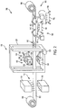
- Fig. 2 is a schematic diagram of thermoforming system 100 incorporating a roll-to-roll process, a forming press having multifaceted tooling, and a modular design.
- Fig. 3 is a schematic partial view of an illustrative forming press, showing a textured mold and a three-layer web material. Although three layers are portrayed, any suitable number of layers may be utilized.
- Figs. 4A and 4B depict a schematic partial side view of an illustrative forming press, showing simultaneous thermoforming of a thermoplastic material and integration of an additional component into a formed part.
- thermoforming system 100 includes a sheet or web of thermoplastic 102 continuously fed through a process from a first roll 104 to a second roll 106.
- Thermoplastic 102 may include any suitable thermoplastic, and may further include one or more additional layers of material laminated or otherwise affixed to the thermoplastic substrate.
- a decorative film may be laminated on either face of the thermoplastic layer, such as depicted in Fig. 3 , where thermoplastic 102 is sandwiched between a top decorative film layer 108 and a bottom decorative film layer 110.
- component layers may be fed through the system separately, being bonded or laminated together in the thermoforming process.
- Various aspects of layered panel manufacturing are known.
- an interior aircraft panel formed by system 100 may have a pair of thermoplastic sheets (also referred to as facings) separated by a reinforcement core to enhance properties such as noise attenuation, thermal insulation, or structural rigidity.
- the reinforcement core may include any suitable material disposed between the two facings to improve certain panel properties such as acoustic attenuation, thermal insulation and/or strength to support compressive fastening loads and provide increased stiffness.
- the core may be provided from a roll, or may be provided as individual panels.
- the core may be a honeycomb core (for strength), an open-cell or closed-cell foam for acoustic and/or thermal insulation, or a fibrous mat for acoustic and/or thermal insulation or a combination thereof (e.g., a combination of foam core and honeycomb core).
- a closed-cell or open-cell (or combination thereof) foam core or a fibrous mat having thermal and/or acoustic insulation properties may be attached to the external surface of one of the facings.
- the core may include one or more rods to improve noise attenuation.
- the rods may be solid or hollow in cross-section and composed of polymer, metal, non-metal or various combinations thereof, such as metallic wire covered with plastic.
- the polymer rods may be fabricated from a thermoplastic material such as polyetherimide, polyphenisulfone or polyarylsulfone.
- the decorative or ornamental film(s) may be opaque or transparent, patterned or printable (e.g., polyvinylfluoride and polyvinyldinefluoride).
- a transparent film may be printed from the backside using ultra-violet radiation to protect the film from solvent abrasion and fading.
- a decorative film material that is compatible with the plastic substrate may be automatically integrated to the base facing during the forming cycle by fusion (heat and pressure). Another option is to install heat-activated adhesive film.
- Preheat oven 112 may include any suitable heating component configured to raise the temperature of thermoplastic sheet 102 prior to downstream thermoforming operations.
- Preheat oven 112 may include an upper heating element 114 and a lower heating element 116, such that both major faces of sheet 102 are heated, e.g., evenly.
- One or more preheat ovens 112 may be present.
- Ovens may be modular and portable, such that different numbers and/or types of ovens may be placed online as needed.
- thermoforming press 118 which is shown schematically in Fig. 2 , includes an outer housing 120 and mold tooling 122.
- Outer housing 120 may include any suitable structure configured to separate the forming apparatus from the outside environment, such as for personnel safety reasons and/or contaminant prevention.
- a pressure box or pressure container (not pictured) may also be present to selectively control pressurization / depressurization of the forming area.
- Mold tooling 122 may include a pair of mating tools.
- mold tooling includes a mold tool 124 and a corresponding press tool 126.
- Mold tool 124 may have a first topology including a male portion, a female portion, or a combination thereof, corresponding to the desired shape of a panel or other part being manufactured. Mold tool 124 is the lower of the two tools, and is configured to remain stationary during operation of forming press 118.
- Press tool 126 is the upper of the two tools, and is configured to translate up and down relative to mold tool 124 during operation. Press tool 126 has a second topology configured to mate with the first topology of mold tool 124.
- forming press 118 operates in similar fashion to a standard forming press, in that the mating tools come together, with sheet 102 between them, to form the thermoplastic sheet into a desired configuration.
- the press may generate aircraft interior panels.
- press tool 126 may include a selectively rotatable or rotary tool having multiple faces 128, wherein each face has a functional press tool topology.
- press tool 126 may include four faces on a cuboidal tool.
- Press tool 126 may be selectively rotatable, as described, e.g., on an axle 130 having a substantially horizontal orientation. Press tool 126 would remain fixed with respect to the axle during normal operations. Rotation of press tool 126 would be performed when a different topology was desired, such that a different face should be presented to the opposing mold tool. This may be performed, for example, when changing from one product line to another, or when changing the desired molding characteristics.
- the number of tool faces 128 may be selected based on several factors, including the number of different panels to be manufactured for a given project or a specified vehicle (e.g., aircraft model). Any suitable number of faces 128 may be present. Any or all of the faces may be utilized in pressing operations. In some examples, one or more faces may be used for other purposes, such as to store reserve tooling accessories in a heated environment.
- Press tool 126 and/or mold tool 124 may be heated, such as by an internal heating mechanism.
- the heating mechanism may include an inductive heating element 132 disposed in press tool 126 and/or in mold tool 124.
- press tool 126 may be heated to a higher temperature than mold tool 124.
- Each face 128 of press tool 126 may include a removable insert 134, such that the press tool is configured to securely receive the inserts.
- Inserts 134 each include a specific topology to be used in pressing the thermoplastic sheet.
- one insert 134 may include two projections and one recess, while another insert 134 includes a single curved surface. Use of such inserts facilitates a standard press tool that does not need to be replaced when desired topologies change, such as when pressing parts for a different project or aircraft model. Time that would typically be used to heat the press tool is also reduced, because the tool itself remains in place during change overs. Only the tooling inserts need to be replaced.
- the set of inserts may include inserts 134 comprising any suitable material configured to withstand forming pressures and temperatures, and to conduct heat to the thermoplastic sheet.
- inserts 134 are metallic.
- one or more inserts 134 are made of a 3-D printable material. Printable inserts allow rapid prototyping, repairs, and responsive design changes, among other benefits.
- mating of the press tool and the mold tool can only be achieved if both the press tool and the mold tool are changed to corresponding topologies.
- both press tool 126 and mold tool 124 may be rotatable and include multiple faces.
- mold tool 124 may be changed over by complete replacement, such as by removal of a first mold tool and installation of a second mold tool.
- mold tool 124 may be usable with multiple different press tool face inserts.
- only a single tool may be used, such as in a vacuum forming operation.
- mold tool 124' includes a textured surface.
- Any suitable textured surface may be utilized and transferred to the thermoplastic part during the pressing operation.
- the textured surface is optional, and may be selected based on desired characteristics of the molded part.
- press tool 126' may or may not include a textured surface.
- Figs. 4A and 4B show another illustrative example of a mold tool 124" and a press tool 126", wherein mold tool 124 is configured to receive a component 135 to be integrated into a pressed part 136.
- mold tool 124 is configured to receive a component 135 to be integrated into a pressed part 136.
- component 135 is fused to the part by a combination of heat, pressure, and/or adhesive.
- the pressing station may include a pick-and-place industrial robot 138 or the like.
- Robot 138 may include any suitable industrial equipment configured to place items such as component 135 onto mold tool 124 and/or press tool 126, and/or to assist with changing over the press tooling.
- robot 138 may assist in interchanging mold parts for specific tool configurations.
- a formed part 140 which may be pre-cut or still unitary with sheet 102, will exit the press and proceed to a finishing station 142.
- a finishing robot 144 may be disposed adjacent to sheet 102 in finishing station 142, such that the finishing robot is capable of performing finishing operations on formed part 140.
- finishing robot 144 may include an end effector 146 that has tools for cutting, punching, grinding, sanding, etching, heating, bonding, fastening, rotating, drilling, and/or the like, or any combination of these. Accordingly, finishing robot 144 may perform operations on part 140, such as formation of windows, apertures, surface features, and the like.
- finishing robot 144 may cut part 140 from sheet 102 and/or perform trimming of the part. In other examples, a separate trimming station may be established.
- a second robot 148 may be stationed at the finishing station or trimming station.
- Robot 148 may be a pick-and-place robot having an end effector 150 configured for removing part 140 from sheet 102, possibly trimming the part, and placing the part on a nearby cart 152 or other conveyance or container.
- Cart 152 may include any suitable cart, such as a wheeled cart having a receiving surface for securely receiving one or more parts 140 from robot 148.
- cart 152 may include one or more clamping mechanisms 154 removably securable to corresponding features of the floor or other support surface. Such clamping ensures the carts are positively located.
- a second cart 156 which may be similar to cart 152, may be disposed between or adjacent to robots 144 and 148.
- Cart 156 may include alternative and/or replacement tools or end effector parts usable by the robots, indicated at 158.
- Robot 144 and/or robot 148 may be configured to automatically replace certain tools at specified intervals, e.g., based on time or number of operations performed. In some examples, an operator may initiate such tool changes, e.g., by remote, programmed control of a robot.
- a scrap recovery station 160 may include take-up roll 106 to collect what remains of sheet 102 after pressed and finished parts are removed.
- thermoforming systems described herein provide several advantages over known solutions for manufacturing parts such as interior panels for aircraft.
- illustrative examples described herein allow continuous feeding of a sheet of material through the system, from roll to roll without any kits or blanks.
- thermoplastic material allows integration of color, texture, and/or ornamental designs in or on the thermoplastic material.
- illustrative examples described herein allow multiple mold tooling faces on a single rotatable core, facilitating rapid changeover of the process. Additionally, replaceable tooling inserts permit additional flexibility and changeability.
Landscapes
- Engineering & Computer Science (AREA)
- Mechanical Engineering (AREA)
- Manufacturing & Machinery (AREA)
- Casting Or Compression Moulding Of Plastics Or The Like (AREA)
- Blow-Moulding Or Thermoforming Of Plastics Or The Like (AREA)
- Moulds For Moulding Plastics Or The Like (AREA)
Description
- This disclosure relates to systems and methods for manufacturing thermoplastic objects. More specifically, the disclosed examples relate to systems and methods for manufacturing thermoplastic parts using a forming press having multifaceted mold tooling.
- The fabrication of molded interior aircraft components from thermoset composite materials is well known in the art. However, the current materials and fabrication methods for fabricating sidewall and ceiling panels for aircraft suffer from very long fabrication cycle-time, material waste and disposal cost. Known thermoset methods involve numerous processing cycles with individually fabricated components converted to sub-assemblies. The sub-assemblies are manually assembled at a significant cost and weight, and retain product deficiencies and waste. Known processes also require multiple complex tools and equipment, which require long lead times, storage facilities and infrastructure. Custom treatments of composite panels are also required to address thermal insulation and noise generated by airflow, equipment and other systems. Known processes do not allow for the integration of new decorative texture uniformity that is required by complex design configurations. The current process is also not tool-side controlled, which affords part-to-part variability and requires repairs.
- Existing composite constructions often contain multiple materials that exhibit only a small difference in their thermal properties. However, the processing methods that utilize a uniform temperature field to fabricate these existing composite configurations are not optimal for many new materials or material configurations that exhibit highly variable thermal properties. While production of composite structures using these new materials may still be feasible using a multiple stage processing method, it is also inefficient in both time and energy. Single-stage processing is preferred for its efficiency.
- Conventional tooling and fabrication methods also lack the capability to fabricate net size parts. This results in excessive material trim-off from the part periphery and internal cut-outs. Thermoset materials are not reusable, and thus the trimming results in added material waste, while also inducing residual stresses and embrittlement that can change the service life of the component.
- Additionally, conventional tooling and fabrication methods involve lengthy change-over times with extensive, time-consuming preheating of dies and other components.
- There is a need for panel fabrication processes that avoid the above-stated disadvantages and impart additional improvements.
-
DE-C1-3929135 relates to an apparatus for deforming thermoplastic materials or for laminating carrier parts with such materials, comprising a lower lifting table with at least one lower tool, an upper lifting table, and at least two different upper tools. -
DE-A1-10022269 relates to a method for performing a product change in thermoforming operations, in which both the lower tool, the clamping frame, and the upper tool are changed. -
US-A1-2005/186303 , in accordance with its abstract, states in the case of a thermoforming system, it is provided, for the purpose of changing over the moulds in a station of this system, that one of the two transporting devices, for transporting the sheet from one station to the other, can be displaced in the direction of the other transporting device, transversely to the conveying direction, in order to create space on one side of the lifting tables so that it is possible for the mould block to be moved out of the station onto a mould-changing arm and, from there, onto a mould-changing carriage. -
WO-A1-2015/035970 , in accordance with its abstract, states a method and a thermoforming or joining system for embedding an embedding element in a product. The use of in-mould labelling technology in thermoforming systems has become known more recently. The reference proposes embedding elements in the products to be produced in thermoforming or joining systems; for example, when particular mechanical protection is desired for the elements to be embedded, which can be desired especially in the case of intelligent components such as RFID transponders or other chips. Injection-moulded parts can also be mechanically connected to thermoformed or joined parts. -
US-A1-2015/251366 , in accordance with its abstract, states a plant for reshaping plastic preforms into plastic containers, includes a heating device for heating the plastic preforms, and a device for reshaping the plastic preforms into the plastic containers, arranged downstream of the heating device in the transport direction of the plastic preforms, wherein the reshaping device includes a transport device, which transports the plastic preforms along a predefined transport path and wherein the transport device has a station carrier on which a multitude of reshaping stations are arranged, each having blow mold devices each arranged on blow mold carriers. The reshaping device includes a changing device, which is suited and intended for at least removing and/or attaching the blow mold devices to the blow mold carriers, wherein this changing device is further suited and intended for at least removing and/or attaching the changeable element to the heating device. -
JP-A-08001709 -
US-A1-2014/004219 , in accordance with its abstract, states a system for aiding in the replacement of a mould of a moulding unit of a machine for manufacturing containers, includes at least one transport device for transporting a joined mold forming a transportable unit subassembly, the transport device including at least one robotic arm for positioning, in space along a trihedron and with respect to the molding unit, elements for handling at least one joined mold so as to carry out a replacement of the at least one mold of the molding unit. - The present disclosure provides systems, apparatuses, and methods relating to forming of thermoplastic parts. Described herein is a method of forming a thermoplastic part, the method comprising steps of: feeding a thermoplastic material into a preheating oven to form a preheated thermoplastic material; feeding the preheated thermoplastic material into a forming press to form a pressed thermoplastic part, wherein the forming press comprises a first tool and a second tool, wherein at least the first tool comprises a rotary tool having multiple faces, each face having a different mold configured for forming a different part in the thermoplastic material, wherein each face of the rotary tool has a receiving structure for securing interchangeable inserts, each insert having a different mold configuration; and finishing the pressed thermoplastic part.
- Also described herein is a forming press comprising: a mold tool and a press tool, wherein at least one of the mold tool and press tool comprises a rotary tool having multiple faces, each face having a different mold configured for forming a different part in a thermoplastic material, each face of the rotary tool having a receiving structure for securing interchangeable inserts, each insert having a different mold configuration, preferably wherein the rotary tool has a heating mechanism.
- Also described herein is a system for forming a thermoplastic part, comprising: a thermoplastic source station; a pressing station comprising a forming press comprising: a mold tool and a press tool, wherein at least one of the mold tool and press tool comprises a rotary tool having multiple faces, each face having a different mold configured for forming a different part in a thermoplastic material, each face of the rotary tool having a receiving structure for securing interchangeable inserts, each insert having a different mold configuration, preferably wherein the rotary tool has a heating mechanism; and a finishing station, a continuous processing path being defined from a roll of thermoplastic web material at the thermoplastic source station, through the pressing station, and the finishing station, preferably, wherein the pressing station includes a tool having an internal heating mechanism.
- Features, functions, and advantages may be achieved independently in various aspects of the present disclosure, or may be combined in yet other examples, further details of which can be seen with reference to the following description and drawings.
-
-
Fig. 1 is a flow chart showing steps of an illustrative method for forming a thermoplastic part using a press having multifaceted mold tooling in accordance with aspects of the present disclosure. -
Fig. 2 is a schematic diagram of an illustrative manufacturing system for forming thermoplastic parts in accordance with aspects of the present disclosure. -
Fig. 3 is a schematic diagram of an illustrative forming press having textured mold tooling. -
Figs. 4A and 4B depict a schematic diagram of an illustrative forming press showing incorporation of additional materials, and an illustrative part resulting from the process. - Various examples of a thermoforming system having rotating, multifaceted mold tooling, as well as related methods, are described below and illustrated in the associated drawings. Unless otherwise specified, a thermoforming system and/or its various components may, but are not required to, contain at least one of the structure, components, functionality, and/or variations described, illustrated, and/or incorporated herein. Furthermore, the process steps, structures, components, functionalities, and/or variations described, illustrated, and/or incorporated herein in connection with the present teachings may, but are not required to, be included in other similar thermoforming systems. The following description of various examples is merely exemplary in nature and is in no way intended to limit the disclosure, its application, or uses. Additionally, the advantages provided by the examples, as described below, are illustrative in nature and not all examples provide the same advantages or the same degree of advantages.
- Thermoset methods and materials are typically used in conventional applications in various industries. For example, thermoset methods and materials have been used in the aerospace industry to manufacture non-structural, non-metallic aircraft composite parts such as ceiling panels, sidewalls, stowbins, and class dividers. Thermosetting plastics are initially soft, and are changed irreversibly to a hardened final state by curing (e.g., using heat). Thermoset operations usually involve perishable raw materials, a large amount of work in process (WIP), long warm up cycles, extensive secondary finishing operations, and lengthy changeover procedures. In contrast, use of thermoplastics and thermoforming operations to manufacture the same parts and components can include greatly reduced WIP, raw materials that may be stored indefinitely at room temperature, and substantial elimination of waste, among other benefits.
- In general, a modular thermoforming system in accordance with aspects of the present disclosure may include a continuous web or sheet of thermoplastic material, which is fed (e.g., from a spooled roll of material) through one or more preheating ovens. The preheating oven heats the web to soften the thermoplastic material. The web is then fed, in continuous fashion, into a forming press, where a mating mold closes on the web. A pressure container (also referred to as a pressure box) may also close around the molded area. The mating mold tooling, comprising a male mold and a female mold (also referred to in some cases as a punch and die, respectively, or as two forming dies, or as a press tool and a mold tool) may include multifaceted components (i.e., having multiple faces). For example, a die may have a plurality of faces, each of which includes a different forming mold or die. For example, a cuboidal die or mold may include four such faces. While four faces are discussed herein, a multifaceted die may include any suitable polygonal cross section and corresponding number of faces. Each face may be configured to receive and retain replaceable tooling. In some examples, the replaceable tooling takes the form of an insert removably attachable to the face of the die.
- Any one of the die faces may be placed into service, by rotating the die about an axis running parallel to the faces. Accordingly, the multifaceted tooling may be referred to as rotating, rotatable, and/or rotisserie. In some examples, the multifaceted tool may rotate about a horizontal axis. In some examples, the multifaceted tool may rotate about a vertical axis. In some examples, the multiple faces may form an array, such that faces may be moved into or out of position by horizontal translation. Each of these examples assumes a substantially horizontal processing path. Other orientations may be appropriate.
- Forming may be assisted by pressure and/or vacuum, which may be facilitated by the pressure container. Additional components, such as stiffening members, may be incorporated into the formed part during the forming process, as further described below. These additional components may provide various characteristics, such as stiffening, rigidity, acoustical properties, and the like.
- Following the die forming process, the web may be fed out of the press and into a finishing area. Using one or more robots or other manipulating systems, openings or apertures may be formed in the part. The same or different robotic systems may cut the part from the web, and may trim and place the part onto a receiving cart or conveyor for transport to another process, or to a storage area. Remaining portions of the web may be spooled on a receiving spool for reuse or recycling.
- "Thermoplastic" or "thermoplastics" refers to a type of plastic material (or polymer) which softens and can be formed into a new shape when heated above its glass transition temperature, and which then solidifies upon cooling, substantially retaining the new shape. This process is typically reversible and repeatable, such that thermoplastics may be recycled (e.g., reshaped). Forming may be accomplished by any suitable method, such as compression molding, vacuum molding, extrusion, injection molding, and the like, or any combination of these. Examples of thermoplastics include acrylics, acrylonitrile butadiene styrene (ABS), nylon, polyethylene, polyetherether ketone (PEEK), polypropylene, polystyrene, and polyvinyl chloride (PVC), among others. Other examples may include materials suitable for high temperature systems, such as PEI, PPS, PPSU, PEKK, and for lower temperature systems, such as polycarbonate and polyurethane.
- The following sections describe selected aspects of exemplary thermoforming systems as well as related systems and/or methods. The examples in these sections are intended for illustration and should not be interpreted as limiting the entire scope of the present disclosure. Each section may include one or more distinct inventions, and/or contextual or related information, function, and/or structure.
- As shown in
Fig. 1 , this section describes selected operations of athermoforming method 10.Fig. 1 is a flowchart illustrating operations performed by one example, and may not recite the complete process or all steps of the method.Fig. 1 depicts multiple steps of a method, generally indicated at 10, which may be performed in conjunction with thermoforming systems according to aspects of the present disclosure. Although various steps ofmethod 10 are described below and depicted inFig. 1 , the steps need not necessarily all be performed, and in some cases may be performed in a different order than the order shown. - In an
operation 12, thermoplastic material may be fed intosystem 10. The thermoplastic material may be fed continuously, such as from a roll or spool of material. The material may include an extruded sheet or web of thermoplastic. In some examples, the thermoplastic web may be laminated or otherwise paired with other materials, such as a decorative film, foam panels, thermoplastic honeycomb structures, unidirectional strips, and/or reinforced thermoplastic strips. Feeding of the material may be achieved by any suitable method or device. For example, powered rollers, a chain conveyor, a pin conveyor, and/or the like, or any combination of these may be utilized. - In an
operation 14, the thermoplastic material may be heated (e.g., preheated), such as in an oven. For example, one or more convection and/or conduction heater elements may be disposed adjacent to the sheet of thermoplastic. For example, the sheet may be conveyed through an oven. In some examples, localized heating may be employed, such as using an infrared (IR) heating element. Localized heating may be appropriate for various applications, including thermally bonding components to a core or substrate. Furthermore, heating may be performed at one or multiple stations. For example, heating may be performed upstream of a forming press, downstream of a forming press, or both. - In an
operation 16, the preheated thermoplastic material may be formed by a forming press having rotatable, multifaceted tooling. For example, a forming press may include mating molds, such that the sheet is conveyed to a position adjacent a first mold having a first mold shape. A second mold, having a second mold shape configured to mate with the first mold, may be forcibly brought into contact with the sheet, pressing the sheet onto and/or into the first mold. In other words, the forming press may be closed onto the thermoplastic sheet. The first and/or second mold may be heated, such as by an internal heating mechanism. After a predetermined time, the forming press may be opened, and the formed sheet may be cooled (actively and/or passively), such that the sheet retains a shape conforming to the press molds. One or both of the press molds may be multifaceted. In other words, different mold faces may be present on a single mold tool, such that a selected mold face can be rotated into an operational position. In some examples, both the first and the second mold tools are rotatable, such that corresponding male and female mold faces can be matched by rotating into position. In some examples, each mold tool is rotatable such that the rotational axis is transverse to the pressing motion. For example, a press in which one or both forming molds are moved vertically may include tooling that selectively rotates on a horizontal axis. - In an
operation 18, the formed thermoplastic material may be finished and/or removed from the continuous sheet of material. For example, the formed thermoplastic material may comprise a part to be utilized in a larger assembly, a further step in a manufacturing process, and/or a standalone object. Accordingly, the formed material may be transformed into a finished part by operations such as scribing, cutting, trimming, punching, printing, painting, and/or the like, or any combination of these. Note that "finishing" in this context is with respect to the present operation, and not necessarily as to the overall manufacturing process. In some examples, the formed material may have one or more apertures or openings cut or punched, then be cut from the larger web of material, and trimmed to a selected tolerance. Finishing operations such as these may be performed by any suitable equipment or device, such as one or more robots having suitable end effectors, one or more punch presses, one or more printers, etc. In some examples, an industrial robot may be utilized for more than one such operation. For example, a robot may have a multi-function end effector and/or the capability of replacing end effectors as needed. - In an
operation 20, the remaining portion of the thermoplastic material may be collected as recyclable scrap. Portions of the thermoplastic material may be reclaimed and recycled at any suitable location along the processing path. For example, after removal of the part from the sheet of thermoplastic material, the remaining scrap can be spooled onto a collection roll and processed for recycling. This capability adds significant flexibility to design of the parts, because scrap reduction is less of a priority than it is in processes where the scrap is unusable. For example, in this thermoplastic process, there is a greatly reduced need for tessellation or tiling of adjacent parts and/or successive parts may be spaced from each other if desired. - In an
operation 22, the part that was finished inoperation 18 may be transported, such as to a subsequent manufacturing process, a storage area, a shipping area, or the like. For example, a pick-and-place robot or other machine may be used to remove the finished part from the finishing area and to place the finished part onto a transportation cart, onto a conveyor, or into a container. Multiple finished parts may be stacked or otherwise arranged for storage or transportation. - As shown in
Figs. 2-4 , this section describes athermoforming system 100, which, among other things, may be suitable for implementingmethod 10. -
Fig. 2 is a schematic diagram ofthermoforming system 100 incorporating a roll-to-roll process, a forming press having multifaceted tooling, and a modular design.Fig. 3 is a schematic partial view of an illustrative forming press, showing a textured mold and a three-layer web material. Although three layers are portrayed, any suitable number of layers may be utilized.Figs. 4A and 4B depict a schematic partial side view of an illustrative forming press, showing simultaneous thermoforming of a thermoplastic material and integration of an additional component into a formed part. - With reference to
Fig. 2 ,thermoforming system 100 includes a sheet or web of thermoplastic 102 continuously fed through a process from afirst roll 104 to asecond roll 106.Thermoplastic 102 may include any suitable thermoplastic, and may further include one or more additional layers of material laminated or otherwise affixed to the thermoplastic substrate. For example, a decorative film may be laminated on either face of the thermoplastic layer, such as depicted inFig. 3 , where thermoplastic 102 is sandwiched between a topdecorative film layer 108 and a bottomdecorative film layer 110. - More or fewer component layers, facings, and configurations may be used with
system 100. In some examples, component layers may be fed through the system separately, being bonded or laminated together in the thermoforming process. Various aspects of layered panel manufacturing are known. - In some examples, an interior aircraft panel formed by
system 100 may have a pair of thermoplastic sheets (also referred to as facings) separated by a reinforcement core to enhance properties such as noise attenuation, thermal insulation, or structural rigidity. The reinforcement core may include any suitable material disposed between the two facings to improve certain panel properties such as acoustic attenuation, thermal insulation and/or strength to support compressive fastening loads and provide increased stiffness. The core may be provided from a roll, or may be provided as individual panels. The core may be a honeycomb core (for strength), an open-cell or closed-cell foam for acoustic and/or thermal insulation, or a fibrous mat for acoustic and/or thermal insulation or a combination thereof (e.g., a combination of foam core and honeycomb core). Alternatively or additionally, a closed-cell or open-cell (or combination thereof) foam core or a fibrous mat having thermal and/or acoustic insulation properties may be attached to the external surface of one of the facings. - The core may include one or more rods to improve noise attenuation. The rods may be solid or hollow in cross-section and composed of polymer, metal, non-metal or various combinations thereof, such as metallic wire covered with plastic. In a preferred example, the polymer rods may be fabricated from a thermoplastic material such as polyetherimide, polyphenisulfone or polyarylsulfone.
- The decorative or ornamental film(s) may be opaque or transparent, patterned or printable (e.g., polyvinylfluoride and polyvinyldinefluoride). A transparent film may be printed from the backside using ultra-violet radiation to protect the film from solvent abrasion and fading. A decorative film material that is compatible with the plastic substrate may be automatically integrated to the base facing during the forming cycle by fusion (heat and pressure). Another option is to install heat-activated adhesive film.
-
Thermoplastic sheet 102 is fed through apreheat oven 112.Preheat oven 112 may include any suitable heating component configured to raise the temperature ofthermoplastic sheet 102 prior to downstream thermoforming operations.Preheat oven 112 may include anupper heating element 114 and alower heating element 116, such that both major faces ofsheet 102 are heated, e.g., evenly. One or morepreheat ovens 112 may be present. Ovens may be modular and portable, such that different numbers and/or types of ovens may be placed online as needed. - Following the preheat oven,
thermoplastic sheet 102 is fed into athermoforming press 118, also referred to as a pressing station.Thermoforming press 118, which is shown schematically inFig. 2 , includes anouter housing 120 andmold tooling 122.Outer housing 120 may include any suitable structure configured to separate the forming apparatus from the outside environment, such as for personnel safety reasons and/or contaminant prevention. A pressure box or pressure container (not pictured) may also be present to selectively control pressurization / depressurization of the forming area. -
Mold tooling 122 may include a pair of mating tools. In the example depicted inFig. 2 , mold tooling includes amold tool 124 and acorresponding press tool 126.Mold tool 124 may have a first topology including a male portion, a female portion, or a combination thereof, corresponding to the desired shape of a panel or other part being manufactured.Mold tool 124 is the lower of the two tools, and is configured to remain stationary during operation of formingpress 118. -
Press tool 126 is the upper of the two tools, and is configured to translate up and down relative tomold tool 124 during operation.Press tool 126 has a second topology configured to mate with the first topology ofmold tool 124. In general, formingpress 118 operates in similar fashion to a standard forming press, in that the mating tools come together, withsheet 102 between them, to form the thermoplastic sheet into a desired configuration. For example, the press may generate aircraft interior panels. - In contrast to known thermoforming presses, however,
press tool 126 may include a selectively rotatable or rotary tool havingmultiple faces 128, wherein each face has a functional press tool topology. For example, as shown inFig. 2 ,press tool 126 may include four faces on a cuboidal tool.Press tool 126 may be selectively rotatable, as described, e.g., on anaxle 130 having a substantially horizontal orientation.Press tool 126 would remain fixed with respect to the axle during normal operations. Rotation ofpress tool 126 would be performed when a different topology was desired, such that a different face should be presented to the opposing mold tool. This may be performed, for example, when changing from one product line to another, or when changing the desired molding characteristics. - The number of tool faces 128 may be selected based on several factors, including the number of different panels to be manufactured for a given project or a specified vehicle (e.g., aircraft model). Any suitable number of
faces 128 may be present. Any or all of the faces may be utilized in pressing operations. In some examples, one or more faces may be used for other purposes, such as to store reserve tooling accessories in a heated environment. -
Press tool 126 and/ormold tool 124 may be heated, such as by an internal heating mechanism. For example, the heating mechanism may include aninductive heating element 132 disposed inpress tool 126 and/or inmold tool 124. In some examples,press tool 126 may be heated to a higher temperature thanmold tool 124. - Each
face 128 ofpress tool 126 may include aremovable insert 134, such that the press tool is configured to securely receive the inserts.Inserts 134 each include a specific topology to be used in pressing the thermoplastic sheet. For example, oneinsert 134 may include two projections and one recess, while anotherinsert 134 includes a single curved surface. Use of such inserts facilitates a standard press tool that does not need to be replaced when desired topologies change, such as when pressing parts for a different project or aircraft model. Time that would typically be used to heat the press tool is also reduced, because the tool itself remains in place during change overs. Only the tooling inserts need to be replaced. - The set of inserts may include
inserts 134 comprising any suitable material configured to withstand forming pressures and temperatures, and to conduct heat to the thermoplastic sheet. In some examples, inserts 134 are metallic. In some examples, one ormore inserts 134 are made of a 3-D printable material. Printable inserts allow rapid prototyping, repairs, and responsive design changes, among other benefits. - In some examples, mating of the press tool and the mold tool can only be achieved if both the press tool and the mold tool are changed to corresponding topologies. In those examples, both
press tool 126 andmold tool 124 may be rotatable and include multiple faces. In other examples,mold tool 124 may be changed over by complete replacement, such as by removal of a first mold tool and installation of a second mold tool. In other examples,mold tool 124 may be usable with multiple different press tool face inserts. In still other examples, only a single tool may be used, such as in a vacuum forming operation. - Turning to
Fig. 3 , an illustrative example of a mold tool 124' and a press tool 126' are shown, in which mold tool 124' includes a textured surface. Any suitable textured surface may be utilized and transferred to the thermoplastic part during the pressing operation. The textured surface is optional, and may be selected based on desired characteristics of the molded part. Similarly, press tool 126' may or may not include a textured surface. -
Figs. 4A and 4B show another illustrative example of amold tool 124" and apress tool 126", whereinmold tool 124 is configured to receive acomponent 135 to be integrated into apressed part 136. When a thermoplastic sheet 102' is pressed betweenmold tool 124" andpress tool 126" to form pressedpart 136,component 135 is fused to the part by a combination of heat, pressure, and/or adhesive. - Returning to
Fig. 2 , the pressing station may include a pick-and-placeindustrial robot 138 or the like.Robot 138 may include any suitable industrial equipment configured to place items such ascomponent 135 ontomold tool 124 and/orpress tool 126, and/or to assist with changing over the press tooling. For example,robot 138 may assist in interchanging mold parts for specific tool configurations. - Following the pressing operation, a formed
part 140, which may be pre-cut or still unitary withsheet 102, will exit the press and proceed to a finishingstation 142. A finishingrobot 144 may be disposed adjacent tosheet 102 in finishingstation 142, such that the finishing robot is capable of performing finishing operations on formedpart 140. For example, finishingrobot 144 may include anend effector 146 that has tools for cutting, punching, grinding, sanding, etching, heating, bonding, fastening, rotating, drilling, and/or the like, or any combination of these. Accordingly, finishingrobot 144 may perform operations onpart 140, such as formation of windows, apertures, surface features, and the like. In some examples, finishingrobot 144 may cutpart 140 fromsheet 102 and/or perform trimming of the part. In other examples, a separate trimming station may be established. - A
second robot 148 may be stationed at the finishing station or trimming station.Robot 148 may be a pick-and-place robot having anend effector 150 configured for removingpart 140 fromsheet 102, possibly trimming the part, and placing the part on anearby cart 152 or other conveyance or container.Cart 152 may include any suitable cart, such as a wheeled cart having a receiving surface for securely receiving one ormore parts 140 fromrobot 148. In some examples,cart 152 may include one ormore clamping mechanisms 154 removably securable to corresponding features of the floor or other support surface. Such clamping ensures the carts are positively located. - A
second cart 156, which may be similar tocart 152, may be disposed between or adjacent torobots Cart 156 may include alternative and/or replacement tools or end effector parts usable by the robots, indicated at 158.Robot 144 and/orrobot 148 may be configured to automatically replace certain tools at specified intervals, e.g., based on time or number of operations performed. In some examples, an operator may initiate such tool changes, e.g., by remote, programmed control of a robot. - Following the finishing station and/or trimming station, a
scrap recovery station 160 may include take-up roll 106 to collect what remains ofsheet 102 after pressed and finished parts are removed. - The different examples of thermoforming systems described herein provide several advantages over known solutions for manufacturing parts such as interior panels for aircraft. For example, illustrative examples described herein allow continuous feeding of a sheet of material through the system, from roll to roll without any kits or blanks.
- Additionally, and among other benefits, illustrative examples described herein allow integration of color, texture, and/or ornamental designs in or on the thermoplastic material.
- Additionally, and among other benefits, illustrative examples described herein allow multiple mold tooling faces on a single rotatable core, facilitating rapid changeover of the process. Additionally, replaceable tooling inserts permit additional flexibility and changeability.
- Additionally, and among other benefits, illustrative examples described herein allow modularity of system components, such that different types or numbers of each component may easily be included.
- Additionally, and among other benefits, illustrative examples described herein allow recycling and reuse of scrap material.
- No known system or device can perform these functions, particularly with respect to manufacturing of aircraft interior panels. However, not all examples described herein provide the same advantages or the same degree of advantage.
- The disclosure set forth above may encompass multiple distinct examples with independent utility. Although each of these has been disclosed in its preferred form(s), the specific examples thereof as disclosed and illustrated herein are not to be considered in a limiting sense, because numerous variations are possible. To the extent that section headings are used within this disclosure, such headings are for organizational purposes only.
Claims (17)
- A method of forming a thermoplastic part, the method comprising steps of:feeding a thermoplastic material into a preheating oven to form a preheated thermoplastic material (12);feeding the preheated thermoplastic material into a forming press to form a pressed thermoplastic part, wherein the forming press comprises a first tool and a second tool, wherein at least the first tool comprises a rotary tool having multiple faces (16), each face having a different mold configured for forming a different part in the thermoplastic material, wherein each face of the rotary tool has a receiving structure for securing interchangeable inserts, each insert having a different mold configuration; andfinishing the pressed thermoplastic part (18).
- The method of claim 1, further comprising the step of:
rotating the rotary tool to change which face is directed toward the second tool. - The method of claim 1 or 2, wherein the first tool is a press tool, and the second tool is a mold tool preferably wherein the press tool and the mold tool are configured to mate with each other, preferably, each of the first tool and the second tool in the forming press comprises a rotary tool having multiple faces.
- The method of any one of claims 1-3, further comprising the step of:
removing a first insert from the receiving structure on the rotary tool, and replacing it with a second insert. - The method of any one of claims 1-4, further comprising the step of:
translating a web of thermoplastic material from a roll upstream of the preheating oven through a continuous processing path. - The method of any one of claims 1-5, further comprising the step of:
heating one or more of the faces from inside the rotary tool. - The method of any one of claims 1-6, further comprising the step of: embedding an accessory component in the thermoplastic material using the forming press and/or pressing a textured tool surface onto the thermoplastic material in the forming press.
- The method of claim 3, optionally additionally of any one of claims 4-7, further comprising the step of: robotically placing mold parts on the mold tool corresponding to a specific insert panel on a face of the press tool.
- The method of claim 5, optionally additionally of any of claims 6-8, wherein the rotary tool rotates around a substantially horizontal axis to change application of different faces of the rotary tool, preferably, wherein the rotary tool rotates around an axis transverse to a direction of the processing path to change application of different faces of the rotary tool.
- The method of any of claims 1-9, wherein a continuous processing path is defined from a roll of thermoplastic material upstream of the preheating oven through the forming press to a finishing station.
- The method of any one of claims 1-10, further comprising the step of: loading a set of inserts into the rotary tool corresponding to a set of interior panels configured for assembly in a specific aircraft design, preferably the method further comprising the step of: supplying the thermoplastic material with a preformed ornamental design.
- The method of claim 5, optionally additionally of any one of claims 6-11, further comprising the step of: stopping feeding of the web during a pressing step, and simultaneously cutting and removing a finished part from the processing path downstream from the forming press.
- A forming press comprising:a mold tool (124) and a press tool (126),wherein at least one of the mold tool and press tool comprises a rotary tool having multiple faces (128), each face having a different mold configured for forming a different part in a thermoplastic material, each face (128) of the rotary tool having a receiving structure for securing interchangeable inserts (134), each insert having a different mold configuration, preferably wherein the rotary tool has a heating mechanism (132).
- The forming press of claim 13, wherein the rotary tool carries a set of inserts corresponding to a set of thermoplastic interior panels configured for assembly in a specific aircraft design.
- A system for forming a thermoplastic part, comprising:a thermoplastic source station (104);a pressing station (118) comprising the forming press of claim 13 or 14; anda finishing station (142),a continuous processing path being defined from a roll of thermoplastic web material at the thermoplastic source station, through the pressing station, and the finishing station, preferably, wherein the pressing station includes a tool having an internal heating mechanism.
- The system of claim 15, wherein the mold tool (124) and the press tool (126) each comprise a rotary tool having multiple faces (128) for forming different parts.
- The system of claim 15 or 16, further comprising: a preheating station upstream from the pressing station (112).
Applications Claiming Priority (1)
| Application Number | Priority Date | Filing Date | Title |
|---|---|---|---|
| US14/946,720 US10576680B2 (en) | 2015-11-19 | 2015-11-19 | Modular thermoforming system |
Publications (3)
| Publication Number | Publication Date |
|---|---|
| EP3170644A2 EP3170644A2 (en) | 2017-05-24 |
| EP3170644A3 EP3170644A3 (en) | 2017-08-16 |
| EP3170644B1 true EP3170644B1 (en) | 2020-07-29 |
Family
ID=57391779
Family Applications (1)
| Application Number | Title | Priority Date | Filing Date |
|---|---|---|---|
| EP16198658.3A Active EP3170644B1 (en) | 2015-11-19 | 2016-11-14 | Modular thermoforming system, method and apparatus |
Country Status (7)
| Country | Link |
|---|---|
| US (2) | US10576680B2 (en) |
| EP (1) | EP3170644B1 (en) |
| JP (1) | JP6835547B2 (en) |
| CN (2) | CN106738806A (en) |
| BR (1) | BR102016026894B1 (en) |
| CA (1) | CA2941297C (en) |
| ES (1) | ES2826377T3 (en) |
Families Citing this family (27)
| Publication number | Priority date | Publication date | Assignee | Title |
|---|---|---|---|---|
| AR077975A1 (en) | 2009-08-28 | 2011-10-05 | Irm Llc | PIRAZOL PYRIMIDINE DERIVATIVES AND COMPOSITIONS AS PROTEIN KINASE INHIBITORS |
| ITMI20132079A1 (en) * | 2013-12-13 | 2015-06-14 | Antonio Rossini | PACKAGING DEVICE. |
| US20190291333A1 (en) * | 2015-08-14 | 2019-09-26 | Scrape Armor, Inc. | System and method for forming of 3d plastic parts |
| US10603835B2 (en) * | 2017-02-08 | 2020-03-31 | Hall Labs Llc | Pin die thermoforming apparatus |
| CN107160661A (en) * | 2017-06-01 | 2017-09-15 | 邓志军 | A kind of hot-press equipment and processing method of processing 3D bend glasses or safeguard film for cellular phone |
| US10695986B2 (en) | 2017-08-22 | 2020-06-30 | Rohr, Inc. | Method for forming a structural panel |
| GB2566550B (en) * | 2017-09-19 | 2022-07-13 | Gkn Aerospace Services Ltd | Electrothermal heater mat and method of manufacture thereof |
| US11279076B2 (en) * | 2017-12-29 | 2022-03-22 | Irwin Research And Development, Inc. | Former to trim press automated sheet delivery system and method |
| US10954681B2 (en) | 2018-02-15 | 2021-03-23 | Strong Industries, Inc. | Cover for a spa and method of fabricating a cover for a spa |
| US11104096B2 (en) | 2018-08-30 | 2021-08-31 | The Boeing Company | Integrated fastener insert for open cellular sandwich structure and method to install |
| US11662708B2 (en) * | 2018-09-25 | 2023-05-30 | Scott Hinkel | Method of forming a two-dimensional image over a model |
| ES2934657T3 (en) * | 2019-05-16 | 2023-02-23 | Pulpac AB | A method for producing pulp products and a rotary forming mold system |
| DE102019117095A1 (en) * | 2019-06-25 | 2020-12-31 | Kiefel Gmbh | HMI SYSTEM FOR OPERATING A PRODUCTION MACHINE FOR PLASTICS PROCESSING |
| SE1951346A1 (en) * | 2019-11-25 | 2021-05-26 | Soedra Skogsaegarna Ekonomisk Foerening | Apparatus and method for pressure moulding |
| CN111571897A (en) * | 2020-05-25 | 2020-08-25 | 韦邦兰 | Sole pressure appearance equipment |
| US12070894B2 (en) * | 2020-08-06 | 2024-08-27 | Dupont Safety & Construction, Inc. | Trimming of contoured polymeric panels |
| JP2022081437A (en) * | 2020-11-18 | 2022-05-31 | ザ・ボーイング・カンパニー | Cut-out processes for moving-line structure assembly |
| NL2028118B1 (en) * | 2021-04-30 | 2022-11-09 | Boeing Co | Cut-out processes for moving-line structure assembly |
| US11685128B2 (en) * | 2020-12-07 | 2023-06-27 | The Boeing Company | System and method for fabricating a composite structure |
| CN112848013B (en) * | 2021-03-02 | 2022-12-13 | 南丰县致诚科技有限公司 | Extrusion forming equipment for producing PS (polystyrene) plates |
| CN114407242A (en) * | 2021-12-31 | 2022-04-29 | 江苏铭利达科技有限公司 | Multi-angle complex mold |
| US12043000B2 (en) | 2022-04-07 | 2024-07-23 | Rohr, Inc. | Joining thermoplastic components |
| KR20230163619A (en) * | 2022-05-23 | 2023-12-01 | 현대자동차주식회사 | Rotatable mold apparatus |
| US12269224B2 (en) * | 2022-06-24 | 2025-04-08 | The Boeing Company | Systems for forming composite parts, methods of forming composite parts, and methods of precisely performing a plurality of operations on a composite part |
| CN115847777A (en) * | 2022-11-29 | 2023-03-28 | 山东宽原新材料科技有限公司 | Forming equipment for thermoplastic composite material special-shaped plate |
| IT202400004717A1 (en) * | 2024-03-04 | 2025-09-04 | M&S Consulting Sa | PLANT FOR THE PRODUCTION OF INSULATION PANELS FOR VEHICLES USED FOR THE TRANSPORT OF MATERIALS, PREFERABLY SUITABLE FOR THE TRANSPORT OF MATERIALS AT CONTROLLED TEMPERATURES, PROCEDURE FOR THE PRODUCTION OF INSULATION PANELS FOR VEHICLES USED FOR THE TRANSPORT OF MATERIALS, PREFERABLY SUITABLE FOR THE TRANSPORT OF MATERIALS AT CONTROLLED TEMPERATURES AND PANELS MADE WITH THE SAID METHOD |
| WO2025186715A1 (en) * | 2024-03-04 | 2025-09-12 | M&S Consulting Sa | Plant for the production of insulating panels for vehicles suitable for the transport of materials, preferably suitable for the transport of materials at a controlled temperature, process for the production of insulating panels for vehicles suitable for the transport of materials, preferably suitable for the transport of temperature-controlled materials and panels made by said method |
Family Cites Families (29)
| Publication number | Priority date | Publication date | Assignee | Title |
|---|---|---|---|---|
| NL279950A (en) * | 1961-06-20 | |||
| US3099043A (en) * | 1961-10-27 | 1963-07-30 | Phillips Petroleum Co | Method and apparatus for vacuum forming hollow articles |
| US3871611A (en) * | 1973-05-07 | 1975-03-18 | Taketa Phyllis | Mold with removable and replaceable core and cavity inserts |
| DE2806402C3 (en) * | 1978-02-15 | 1980-11-27 | Unilever N.V., Rotterdam (Niederlande) | Method and device for producing a moisture-permeable film made of thermoplastic material |
| US4431397A (en) * | 1978-10-23 | 1984-02-14 | Fried Robert P | Apparatus for producing molded plastic articles |
| DE8007087U1 (en) * | 1980-03-14 | 1982-01-28 | Multivac Sepp Haggenmüller KG, 8941 Wolfertschwenden | MOLDING TOOL, ESPECIALLY FOR A PACKING MACHINE, WITH A MOLDING STAMP |
| US4420300A (en) * | 1980-08-13 | 1983-12-13 | Maryland Cup Corporation | Continuous rotary thermo-forming systems and apparatus of the pressure assist, plug assist and match mold type |
| US4445957A (en) * | 1982-11-22 | 1984-05-01 | General Motors Corporation | Method and means for making constant cross sectional area pultruded fiber reinforced polymeric articles. |
| US4551084A (en) * | 1983-05-25 | 1985-11-05 | Creative Industries, Inc. | Convertible mold |
| US4830596A (en) * | 1988-01-04 | 1989-05-16 | Neu Stephen T | Vacuum thermoforming rotary machine |
| US5366685A (en) * | 1989-07-18 | 1994-11-22 | Idemitsu Petrochemical Co., Ltd. | Process of molding thermoplastic sheet by plug assist vacuum forming |
| DE3929135C1 (en) | 1989-09-01 | 1990-10-18 | Paul Kiefel Gmbh, 8228 Freilassing, De | |
| JPH05104572A (en) | 1991-10-21 | 1993-04-27 | Toppan Printing Co Ltd | Manufacture of multilayer plastic vessel |
| US5395575A (en) * | 1993-09-07 | 1995-03-07 | General Motors Corporation | Rotary reforming of thermoplastics extrudate |
| JP2940850B2 (en) | 1994-06-21 | 1999-08-25 | 株式会社小松ライト製作所 | Automatic molding equipment |
| DE10009403B4 (en) * | 2000-02-28 | 2008-02-21 | Paul Kiefel Gmbh | Device for deforming thermoplastic materials |
| DE10022269B4 (en) | 2000-05-08 | 2016-07-28 | Kiefel Gmbh | Method and device for carrying out a product change in thermoforming processes |
| ITSV20020063A1 (en) * | 2002-12-30 | 2004-06-30 | Compass Sa | SHAPED PANEL IN THERMOPLASTIC MATERIAL, INTERMEDIATE SHEET FOR THE MANUFACTURE OF THE SAID PANEL AND PROCEDURE FOR THE MANUFACTURE OF THE SAID PANEL AND OF THE INTERMEDIATE SHEET |
| DE10345534A1 (en) * | 2003-09-30 | 2005-04-28 | Kiefel Ag | Thermoforming system |
| EP1609574A1 (en) * | 2004-06-23 | 2005-12-28 | Grupo Antolin Ingenieria, S.A. | System and method for manufacturing plastic parts with textile covering |
| US7794224B2 (en) * | 2004-09-28 | 2010-09-14 | Woodbridge Corporation | Apparatus for the continuous production of plastic composites |
| JP2010207902A (en) * | 2009-03-12 | 2010-09-24 | Kitagawa Elaborate Mach Co Ltd | Vacuum press apparatus and vacuum press method |
| US8287270B2 (en) * | 2009-09-30 | 2012-10-16 | Printpack Illinois Inc. | Methods and systems for thermoforming with billets |
| FR2972386B1 (en) | 2011-03-08 | 2014-10-10 | Sidel Participations | ASSEMBLY ASSEMBLY SYSTEM FOR MOLDING UNIT MOLDING MACHINE FOR CONTAINER MANUFACTURING MACHINE |
| US9005730B2 (en) | 2011-11-14 | 2015-04-14 | The Boeing Company | Aircraft interior panels and methods of panel fabrication |
| US20130193599A1 (en) * | 2012-01-27 | 2013-08-01 | Roman's Design | Dual action gyratory thermoforming press |
| CN105531097A (en) | 2013-09-11 | 2016-04-27 | 凯孚尔有限公司 | Method for producing a product by means of a thermoforming or joining system, and a thermoforming or joining system |
| US9815239B2 (en) * | 2014-02-26 | 2017-11-14 | Michael Borse | Rotary thermoforming apparatus and method of using same |
| DE102014103159A1 (en) | 2014-03-10 | 2015-09-24 | Krones Ag | Apparatus and method for forming plastic preforms to plastic containers with automatic changing device for clothing parts |
-
2015
- 2015-11-19 US US14/946,720 patent/US10576680B2/en active Active
-
2016
- 2016-09-07 CA CA2941297A patent/CA2941297C/en active Active
- 2016-11-14 EP EP16198658.3A patent/EP3170644B1/en active Active
- 2016-11-14 CN CN201611002242.XA patent/CN106738806A/en active Pending
- 2016-11-14 CN CN202211087734.9A patent/CN115447113A/en active Pending
- 2016-11-14 ES ES16198658T patent/ES2826377T3/en active Active
- 2016-11-17 BR BR102016026894-0A patent/BR102016026894B1/en active IP Right Grant
- 2016-11-18 JP JP2016225136A patent/JP6835547B2/en active Active
-
2020
- 2020-03-02 US US16/807,062 patent/US11235508B2/en active Active
Non-Patent Citations (1)
| Title |
|---|
| None * |
Also Published As
| Publication number | Publication date |
|---|---|
| CA2941297C (en) | 2020-08-04 |
| CA2941297A1 (en) | 2017-05-19 |
| CN115447113A (en) | 2022-12-09 |
| US10576680B2 (en) | 2020-03-03 |
| US20170144361A1 (en) | 2017-05-25 |
| ES2826377T3 (en) | 2021-05-18 |
| BR102016026894A2 (en) | 2017-05-23 |
| US20200198218A1 (en) | 2020-06-25 |
| US11235508B2 (en) | 2022-02-01 |
| JP6835547B2 (en) | 2021-02-24 |
| BR102016026894B1 (en) | 2021-12-07 |
| JP2017140822A (en) | 2017-08-17 |
| EP3170644A2 (en) | 2017-05-24 |
| EP3170644A3 (en) | 2017-08-16 |
| CN106738806A (en) | 2017-05-31 |
Similar Documents
| Publication | Publication Date | Title |
|---|---|---|
| US11235508B2 (en) | Modular thermoforming system | |
| CN107775972B (en) | end of arm tool | |
| JP6416771B2 (en) | Manufacturing method for structural parts especially for vehicle bodies | |
| JP6892227B2 (en) | Methods and equipment for forming undulating reinforcements | |
| EP2168754A2 (en) | Plastic component, in particular luggage shell, made of self-reinforced thermoplastic material and apparatus for making such a component | |
| JP6109196B2 (en) | Method and apparatus for producing a three-dimensional preform from a fiber scrim during the production of a fiber reinforced molded part | |
| US20080014453A1 (en) | Novel thermoplastic part, tool and method for the manufacturing thereof | |
| Janssen et al. | Efficient production of tailored structural thermoplastic composite parts by combining tape placement and 3d printing | |
| WO2018211232A1 (en) | Stiffening structure for an aircraft door or panel | |
| US11597044B2 (en) | Composite assembly for unhardened fuselage components | |
| EP4008533B1 (en) | System and method for fabricating a composite structure | |
| TW200800554A (en) | Overmolding of inserts | |
| EP3625034B1 (en) | Fastenerless structural assembly | |
| WO2018211234A1 (en) | Door assembly for a vehicle | |
| CA3044213C (en) | Matched compression die apparatus | |
| EP3738754B1 (en) | Method for moulding a composite structure with a superplastic bladder | |
| GB2564753A (en) | Fastenerless structural assembly | |
| KR102529929B1 (en) | System and method for manufacturing composite material | |
| EP4194158B1 (en) | System comprising a scalable area gripper, and method for a material handling process for composite manufacturing | |
| US20250010537A1 (en) | Additively reinforced thermoforming | |
| EP4424502B1 (en) | Blade stringer forming methods and tooling | |
| Penix | Thermoforming of Plastic Film and Sheet | |
| CN118139734A (en) | Mould arrangement for producing a preform element for a wind turbine blade and method for producing a preform for a wind turbine blade | |
| HK1103686B (en) | Process for making a plastic component from self-reinforced thermo-plastic material and plastic component produced by this process | |
| HK1190115A (en) | Process for making a plastic component from self-reinforced thermo-plastic material and plastic component produced by this process |
Legal Events
| Date | Code | Title | Description |
|---|---|---|---|
| PUAI | Public reference made under article 153(3) epc to a published international application that has entered the european phase |
Free format text: ORIGINAL CODE: 0009012 |
|
| STAA | Information on the status of an ep patent application or granted ep patent |
Free format text: STATUS: REQUEST FOR EXAMINATION WAS MADE |
|
| 17P | Request for examination filed |
Effective date: 20161114 |
|
| AK | Designated contracting states |
Kind code of ref document: A2 Designated state(s): AL AT BE BG CH CY CZ DE DK EE ES FI FR GB GR HR HU IE IS IT LI LT LU LV MC MK MT NL NO PL PT RO RS SE SI SK SM TR |
|
| AX | Request for extension of the european patent |
Extension state: BA ME |
|
| PUAL | Search report despatched |
Free format text: ORIGINAL CODE: 0009013 |
|
| RIC1 | Information provided on ipc code assigned before grant |
Ipc: B29C 51/30 20060101AFI20170706BHEP |
|
| AK | Designated contracting states |
Kind code of ref document: A3 Designated state(s): AL AT BE BG CH CY CZ DE DK EE ES FI FR GB GR HR HU IE IS IT LI LT LU LV MC MK MT NL NO PL PT RO RS SE SI SK SM TR |
|
| AX | Request for extension of the european patent |
Extension state: BA ME |
|
| GRAP | Despatch of communication of intention to grant a patent |
Free format text: ORIGINAL CODE: EPIDOSNIGR1 |
|
| STAA | Information on the status of an ep patent application or granted ep patent |
Free format text: STATUS: GRANT OF PATENT IS INTENDED |
|
| RIC1 | Information provided on ipc code assigned before grant |
Ipc: B29C 51/12 20060101ALN20191028BHEP Ipc: B29C 51/26 20060101ALN20191028BHEP Ipc: B29C 51/44 20060101ALN20191028BHEP Ipc: B29C 51/42 20060101ALN20191028BHEP Ipc: B29C 51/30 20060101AFI20191028BHEP Ipc: B29C 51/08 20060101ALN20191028BHEP |
|
| INTG | Intention to grant announced |
Effective date: 20191114 |
|
| GRAJ | Information related to disapproval of communication of intention to grant by the applicant or resumption of examination proceedings by the epo deleted |
Free format text: ORIGINAL CODE: EPIDOSDIGR1 |
|
| STAA | Information on the status of an ep patent application or granted ep patent |
Free format text: STATUS: REQUEST FOR EXAMINATION WAS MADE |
|
| GRAP | Despatch of communication of intention to grant a patent |
Free format text: ORIGINAL CODE: EPIDOSNIGR1 |
|
| STAA | Information on the status of an ep patent application or granted ep patent |
Free format text: STATUS: GRANT OF PATENT IS INTENDED |
|
| INTC | Intention to grant announced (deleted) | ||
| RIC1 | Information provided on ipc code assigned before grant |
Ipc: B29C 51/44 20060101ALN20200207BHEP Ipc: B29C 51/08 20060101ALN20200207BHEP Ipc: B29C 51/30 20060101AFI20200207BHEP Ipc: B29C 51/42 20060101ALN20200207BHEP Ipc: B29C 51/12 20060101ALN20200207BHEP Ipc: B29C 51/26 20060101ALN20200207BHEP |
|
| INTG | Intention to grant announced |
Effective date: 20200226 |
|
| GRAS | Grant fee paid |
Free format text: ORIGINAL CODE: EPIDOSNIGR3 |
|
| GRAA | (expected) grant |
Free format text: ORIGINAL CODE: 0009210 |
|
| STAA | Information on the status of an ep patent application or granted ep patent |
Free format text: STATUS: THE PATENT HAS BEEN GRANTED |
|
| AK | Designated contracting states |
Kind code of ref document: B1 Designated state(s): AL AT BE BG CH CY CZ DE DK EE ES FI FR GB GR HR HU IE IS IT LI LT LU LV MC MK MT NL NO PL PT RO RS SE SI SK SM TR |
|
| REG | Reference to a national code |
Ref country code: CH Ref legal event code: EP |
|
| REG | Reference to a national code |
Ref country code: AT Ref legal event code: REF Ref document number: 1295279 Country of ref document: AT Kind code of ref document: T Effective date: 20200815 |
|
| REG | Reference to a national code |
Ref country code: IE Ref legal event code: FG4D |
|
| REG | Reference to a national code |
Ref country code: DE Ref legal event code: R096 Ref document number: 602016040725 Country of ref document: DE |
|
| REG | Reference to a national code |
Ref country code: DE Ref legal event code: R082 Ref document number: 602016040725 Country of ref document: DE Representative=s name: BOULT WADE TENNANT LLP, DE |
|
| REG | Reference to a national code |
Ref country code: LT Ref legal event code: MG4D |
|
| REG | Reference to a national code |
Ref country code: NL Ref legal event code: MP Effective date: 20200729 |
|
| REG | Reference to a national code |
Ref country code: AT Ref legal event code: MK05 Ref document number: 1295279 Country of ref document: AT Kind code of ref document: T Effective date: 20200729 |
|
| PG25 | Lapsed in a contracting state [announced via postgrant information from national office to epo] |
Ref country code: PT Free format text: LAPSE BECAUSE OF FAILURE TO SUBMIT A TRANSLATION OF THE DESCRIPTION OR TO PAY THE FEE WITHIN THE PRESCRIBED TIME-LIMIT Effective date: 20201130 Ref country code: FI Free format text: LAPSE BECAUSE OF FAILURE TO SUBMIT A TRANSLATION OF THE DESCRIPTION OR TO PAY THE FEE WITHIN THE PRESCRIBED TIME-LIMIT Effective date: 20200729 Ref country code: NO Free format text: LAPSE BECAUSE OF FAILURE TO SUBMIT A TRANSLATION OF THE DESCRIPTION OR TO PAY THE FEE WITHIN THE PRESCRIBED TIME-LIMIT Effective date: 20201029 Ref country code: AT Free format text: LAPSE BECAUSE OF FAILURE TO SUBMIT A TRANSLATION OF THE DESCRIPTION OR TO PAY THE FEE WITHIN THE PRESCRIBED TIME-LIMIT Effective date: 20200729 Ref country code: BG Free format text: LAPSE BECAUSE OF FAILURE TO SUBMIT A TRANSLATION OF THE DESCRIPTION OR TO PAY THE FEE WITHIN THE PRESCRIBED TIME-LIMIT Effective date: 20201029 Ref country code: SE Free format text: LAPSE BECAUSE OF FAILURE TO SUBMIT A TRANSLATION OF THE DESCRIPTION OR TO PAY THE FEE WITHIN THE PRESCRIBED TIME-LIMIT Effective date: 20200729 Ref country code: LT Free format text: LAPSE BECAUSE OF FAILURE TO SUBMIT A TRANSLATION OF THE DESCRIPTION OR TO PAY THE FEE WITHIN THE PRESCRIBED TIME-LIMIT Effective date: 20200729 Ref country code: GR Free format text: LAPSE BECAUSE OF FAILURE TO SUBMIT A TRANSLATION OF THE DESCRIPTION OR TO PAY THE FEE WITHIN THE PRESCRIBED TIME-LIMIT Effective date: 20201030 Ref country code: HR Free format text: LAPSE BECAUSE OF FAILURE TO SUBMIT A TRANSLATION OF THE DESCRIPTION OR TO PAY THE FEE WITHIN THE PRESCRIBED TIME-LIMIT Effective date: 20200729 |
|
| PG25 | Lapsed in a contracting state [announced via postgrant information from national office to epo] |
Ref country code: PL Free format text: LAPSE BECAUSE OF FAILURE TO SUBMIT A TRANSLATION OF THE DESCRIPTION OR TO PAY THE FEE WITHIN THE PRESCRIBED TIME-LIMIT Effective date: 20200729 Ref country code: LV Free format text: LAPSE BECAUSE OF FAILURE TO SUBMIT A TRANSLATION OF THE DESCRIPTION OR TO PAY THE FEE WITHIN THE PRESCRIBED TIME-LIMIT Effective date: 20200729 Ref country code: RS Free format text: LAPSE BECAUSE OF FAILURE TO SUBMIT A TRANSLATION OF THE DESCRIPTION OR TO PAY THE FEE WITHIN THE PRESCRIBED TIME-LIMIT Effective date: 20200729 Ref country code: IS Free format text: LAPSE BECAUSE OF FAILURE TO SUBMIT A TRANSLATION OF THE DESCRIPTION OR TO PAY THE FEE WITHIN THE PRESCRIBED TIME-LIMIT Effective date: 20201129 |
|
| PG25 | Lapsed in a contracting state [announced via postgrant information from national office to epo] |
Ref country code: NL Free format text: LAPSE BECAUSE OF FAILURE TO SUBMIT A TRANSLATION OF THE DESCRIPTION OR TO PAY THE FEE WITHIN THE PRESCRIBED TIME-LIMIT Effective date: 20200729 |
|
| PG25 | Lapsed in a contracting state [announced via postgrant information from national office to epo] |
Ref country code: SM Free format text: LAPSE BECAUSE OF FAILURE TO SUBMIT A TRANSLATION OF THE DESCRIPTION OR TO PAY THE FEE WITHIN THE PRESCRIBED TIME-LIMIT Effective date: 20200729 Ref country code: RO Free format text: LAPSE BECAUSE OF FAILURE TO SUBMIT A TRANSLATION OF THE DESCRIPTION OR TO PAY THE FEE WITHIN THE PRESCRIBED TIME-LIMIT Effective date: 20200729 Ref country code: CZ Free format text: LAPSE BECAUSE OF FAILURE TO SUBMIT A TRANSLATION OF THE DESCRIPTION OR TO PAY THE FEE WITHIN THE PRESCRIBED TIME-LIMIT Effective date: 20200729 Ref country code: DK Free format text: LAPSE BECAUSE OF FAILURE TO SUBMIT A TRANSLATION OF THE DESCRIPTION OR TO PAY THE FEE WITHIN THE PRESCRIBED TIME-LIMIT Effective date: 20200729 Ref country code: EE Free format text: LAPSE BECAUSE OF FAILURE TO SUBMIT A TRANSLATION OF THE DESCRIPTION OR TO PAY THE FEE WITHIN THE PRESCRIBED TIME-LIMIT Effective date: 20200729 Ref country code: IT Free format text: LAPSE BECAUSE OF FAILURE TO SUBMIT A TRANSLATION OF THE DESCRIPTION OR TO PAY THE FEE WITHIN THE PRESCRIBED TIME-LIMIT Effective date: 20200729 |
|
| REG | Reference to a national code |
Ref country code: DE Ref legal event code: R097 Ref document number: 602016040725 Country of ref document: DE |
|
| REG | Reference to a national code |
Ref country code: ES Ref legal event code: FG2A Ref document number: 2826377 Country of ref document: ES Kind code of ref document: T3 Effective date: 20210518 |
|
| PG25 | Lapsed in a contracting state [announced via postgrant information from national office to epo] |
Ref country code: AL Free format text: LAPSE BECAUSE OF FAILURE TO SUBMIT A TRANSLATION OF THE DESCRIPTION OR TO PAY THE FEE WITHIN THE PRESCRIBED TIME-LIMIT Effective date: 20200729 |
|
| PLBE | No opposition filed within time limit |
Free format text: ORIGINAL CODE: 0009261 |
|
| STAA | Information on the status of an ep patent application or granted ep patent |
Free format text: STATUS: NO OPPOSITION FILED WITHIN TIME LIMIT |
|
| PG25 | Lapsed in a contracting state [announced via postgrant information from national office to epo] |
Ref country code: SK Free format text: LAPSE BECAUSE OF FAILURE TO SUBMIT A TRANSLATION OF THE DESCRIPTION OR TO PAY THE FEE WITHIN THE PRESCRIBED TIME-LIMIT Effective date: 20200729 Ref country code: MC Free format text: LAPSE BECAUSE OF FAILURE TO SUBMIT A TRANSLATION OF THE DESCRIPTION OR TO PAY THE FEE WITHIN THE PRESCRIBED TIME-LIMIT Effective date: 20200729 |
|
| REG | Reference to a national code |
Ref country code: CH Ref legal event code: PL |
|
| 26N | No opposition filed |
Effective date: 20210430 |
|
| PG25 | Lapsed in a contracting state [announced via postgrant information from national office to epo] |
Ref country code: LU Free format text: LAPSE BECAUSE OF NON-PAYMENT OF DUE FEES Effective date: 20201114 |
|
| REG | Reference to a national code |
Ref country code: BE Ref legal event code: MM Effective date: 20201130 |
|
| PG25 | Lapsed in a contracting state [announced via postgrant information from national office to epo] |
Ref country code: LI Free format text: LAPSE BECAUSE OF NON-PAYMENT OF DUE FEES Effective date: 20201130 Ref country code: SI Free format text: LAPSE BECAUSE OF FAILURE TO SUBMIT A TRANSLATION OF THE DESCRIPTION OR TO PAY THE FEE WITHIN THE PRESCRIBED TIME-LIMIT Effective date: 20200729 Ref country code: CH Free format text: LAPSE BECAUSE OF NON-PAYMENT OF DUE FEES Effective date: 20201130 |
|
| PG25 | Lapsed in a contracting state [announced via postgrant information from national office to epo] |
Ref country code: IE Free format text: LAPSE BECAUSE OF NON-PAYMENT OF DUE FEES Effective date: 20201114 |
|
| PG25 | Lapsed in a contracting state [announced via postgrant information from national office to epo] |
Ref country code: TR Free format text: LAPSE BECAUSE OF FAILURE TO SUBMIT A TRANSLATION OF THE DESCRIPTION OR TO PAY THE FEE WITHIN THE PRESCRIBED TIME-LIMIT Effective date: 20200729 Ref country code: MT Free format text: LAPSE BECAUSE OF FAILURE TO SUBMIT A TRANSLATION OF THE DESCRIPTION OR TO PAY THE FEE WITHIN THE PRESCRIBED TIME-LIMIT Effective date: 20200729 Ref country code: CY Free format text: LAPSE BECAUSE OF FAILURE TO SUBMIT A TRANSLATION OF THE DESCRIPTION OR TO PAY THE FEE WITHIN THE PRESCRIBED TIME-LIMIT Effective date: 20200729 |
|
| PG25 | Lapsed in a contracting state [announced via postgrant information from national office to epo] |
Ref country code: MK Free format text: LAPSE BECAUSE OF FAILURE TO SUBMIT A TRANSLATION OF THE DESCRIPTION OR TO PAY THE FEE WITHIN THE PRESCRIBED TIME-LIMIT Effective date: 20200729 |
|
| PG25 | Lapsed in a contracting state [announced via postgrant information from national office to epo] |
Ref country code: BE Free format text: LAPSE BECAUSE OF NON-PAYMENT OF DUE FEES Effective date: 20201130 |
|
| P01 | Opt-out of the competence of the unified patent court (upc) registered |
Effective date: 20230516 |
|
| PGFP | Annual fee paid to national office [announced via postgrant information from national office to epo] |
Ref country code: DE Payment date: 20251128 Year of fee payment: 10 |
|
| PGFP | Annual fee paid to national office [announced via postgrant information from national office to epo] |
Ref country code: GB Payment date: 20251127 Year of fee payment: 10 |
|
| PGFP | Annual fee paid to national office [announced via postgrant information from national office to epo] |
Ref country code: FR Payment date: 20251125 Year of fee payment: 10 |
|
| PGFP | Annual fee paid to national office [announced via postgrant information from national office to epo] |
Ref country code: ES Payment date: 20251201 Year of fee payment: 10 |