EP3170617A2 - Fixture and method for resistance welding of a pad to a surface - Google Patents
Fixture and method for resistance welding of a pad to a surface Download PDFInfo
- Publication number
- EP3170617A2 EP3170617A2 EP16199126.0A EP16199126A EP3170617A2 EP 3170617 A2 EP3170617 A2 EP 3170617A2 EP 16199126 A EP16199126 A EP 16199126A EP 3170617 A2 EP3170617 A2 EP 3170617A2
- Authority
- EP
- European Patent Office
- Prior art keywords
- contact surface
- pad
- turbine blade
- fixture
- article
- Prior art date
- Legal status (The legal status is an assumption and is not a legal conclusion. Google has not performed a legal analysis and makes no representation as to the accuracy of the status listed.)
- Granted
Links
Images

Classifications
-
- B—PERFORMING OPERATIONS; TRANSPORTING
- B23—MACHINE TOOLS; METAL-WORKING NOT OTHERWISE PROVIDED FOR
- B23K—SOLDERING OR UNSOLDERING; WELDING; CLADDING OR PLATING BY SOLDERING OR WELDING; CUTTING BY APPLYING HEAT LOCALLY, e.g. FLAME CUTTING; WORKING BY LASER BEAM
- B23K11/00—Resistance welding; Severing by resistance heating
- B23K11/10—Spot welding; Stitch welding
- B23K11/11—Spot welding
-
- B—PERFORMING OPERATIONS; TRANSPORTING
- B23—MACHINE TOOLS; METAL-WORKING NOT OTHERWISE PROVIDED FOR
- B23K—SOLDERING OR UNSOLDERING; WELDING; CLADDING OR PLATING BY SOLDERING OR WELDING; CUTTING BY APPLYING HEAT LOCALLY, e.g. FLAME CUTTING; WORKING BY LASER BEAM
- B23K11/00—Resistance welding; Severing by resistance heating
- B23K11/002—Resistance welding; Severing by resistance heating specially adapted for particular articles or work
-
- B—PERFORMING OPERATIONS; TRANSPORTING
- B23—MACHINE TOOLS; METAL-WORKING NOT OTHERWISE PROVIDED FOR
- B23K—SOLDERING OR UNSOLDERING; WELDING; CLADDING OR PLATING BY SOLDERING OR WELDING; CUTTING BY APPLYING HEAT LOCALLY, e.g. FLAME CUTTING; WORKING BY LASER BEAM
- B23K11/00—Resistance welding; Severing by resistance heating
- B23K11/002—Resistance welding; Severing by resistance heating specially adapted for particular articles or work
- B23K11/004—Welding of a small piece to a large or broad piece
-
- B—PERFORMING OPERATIONS; TRANSPORTING
- B23—MACHINE TOOLS; METAL-WORKING NOT OTHERWISE PROVIDED FOR
- B23K—SOLDERING OR UNSOLDERING; WELDING; CLADDING OR PLATING BY SOLDERING OR WELDING; CUTTING BY APPLYING HEAT LOCALLY, e.g. FLAME CUTTING; WORKING BY LASER BEAM
- B23K11/00—Resistance welding; Severing by resistance heating
- B23K11/10—Spot welding; Stitch welding
- B23K11/11—Spot welding
- B23K11/115—Spot welding by means of two electrodes placed opposite one another on both sides of the welded parts
-
- B—PERFORMING OPERATIONS; TRANSPORTING
- B23—MACHINE TOOLS; METAL-WORKING NOT OTHERWISE PROVIDED FOR
- B23K—SOLDERING OR UNSOLDERING; WELDING; CLADDING OR PLATING BY SOLDERING OR WELDING; CUTTING BY APPLYING HEAT LOCALLY, e.g. FLAME CUTTING; WORKING BY LASER BEAM
- B23K11/00—Resistance welding; Severing by resistance heating
- B23K11/36—Auxiliary equipment
-
- B—PERFORMING OPERATIONS; TRANSPORTING
- B23—MACHINE TOOLS; METAL-WORKING NOT OTHERWISE PROVIDED FOR
- B23K—SOLDERING OR UNSOLDERING; WELDING; CLADDING OR PLATING BY SOLDERING OR WELDING; CUTTING BY APPLYING HEAT LOCALLY, e.g. FLAME CUTTING; WORKING BY LASER BEAM
- B23K37/00—Auxiliary devices or processes, not specially adapted for a procedure covered by only one of the other main groups of this subclass
- B23K37/04—Auxiliary devices or processes, not specially adapted for a procedure covered by only one of the other main groups of this subclass for holding or positioning work
- B23K37/0426—Fixtures for other work
- B23K37/0435—Clamps
-
- B—PERFORMING OPERATIONS; TRANSPORTING
- B23—MACHINE TOOLS; METAL-WORKING NOT OTHERWISE PROVIDED FOR
- B23K—SOLDERING OR UNSOLDERING; WELDING; CLADDING OR PLATING BY SOLDERING OR WELDING; CUTTING BY APPLYING HEAT LOCALLY, e.g. FLAME CUTTING; WORKING BY LASER BEAM
- B23K37/00—Auxiliary devices or processes, not specially adapted for a procedure covered by only one of the other main groups of this subclass
- B23K37/04—Auxiliary devices or processes, not specially adapted for a procedure covered by only one of the other main groups of this subclass for holding or positioning work
- B23K37/0426—Fixtures for other work
- B23K37/0435—Clamps
- B23K37/0443—Jigs
-
- B—PERFORMING OPERATIONS; TRANSPORTING
- B23—MACHINE TOOLS; METAL-WORKING NOT OTHERWISE PROVIDED FOR
- B23Q—DETAILS, COMPONENTS, OR ACCESSORIES FOR MACHINE TOOLS, e.g. ARRANGEMENTS FOR COPYING OR CONTROLLING; MACHINE TOOLS IN GENERAL CHARACTERISED BY THE CONSTRUCTION OF PARTICULAR DETAILS OR COMPONENTS; COMBINATIONS OR ASSOCIATIONS OF METAL-WORKING MACHINES, NOT DIRECTED TO A PARTICULAR RESULT
- B23Q3/00—Devices holding, supporting, or positioning work or tools, of a kind normally removable from the machine
- B23Q3/02—Devices holding, supporting, or positioning work or tools, of a kind normally removable from the machine for mounting on a work-table, tool-slide, or analogous part
- B23Q3/06—Work-clamping means
- B23Q3/062—Work-clamping means adapted for holding workpieces having a special form or being made from a special material
- B23Q3/063—Work-clamping means adapted for holding workpieces having a special form or being made from a special material for holding turbine blades
-
- B—PERFORMING OPERATIONS; TRANSPORTING
- B23—MACHINE TOOLS; METAL-WORKING NOT OTHERWISE PROVIDED FOR
- B23K—SOLDERING OR UNSOLDERING; WELDING; CLADDING OR PLATING BY SOLDERING OR WELDING; CUTTING BY APPLYING HEAT LOCALLY, e.g. FLAME CUTTING; WORKING BY LASER BEAM
- B23K2101/00—Articles made by soldering, welding or cutting
- B23K2101/001—Turbines
Definitions
- the present invention is directed to a fixture and a method for resistance welding. More particularly, the present invention is directed to a fixture and a method for resistance welding of a pad to a surface.
- Certain gas turbine blades have shrouds at the outer extremity of the airfoil.
- the blade shrouds are typically designed with an interlocking feature, usually in the form of a notch, which allows each blade to be interlocked at its shroud with an adjacent neighbor blade when such blades are installed about the circumference of a turbine disk.
- This interlocking feature assists in preventing the airfoils from vibrating, thereby reducing the stresses imparted on the blades during operation.
- Turbine blades are often made of nickel-based superalloys or other high temperature superalloys designed to retain high strength at high temperature.
- the material of the blade shrouds and the interlocking notch may lack sufficient hardness to withstand wear stresses and rubbing which occur during start-up and shut-down of a turbine engine, as the shrouded blades twist to an "interlocked” and "non-interlocked” position, respectively.
- the interlocks may wear, resulting in gaps opening between the blade shrouds, thereby allowing the airfoils to twist and further deform, and even to possibly vibrate during operation which is highly undesirable as such imparts additional higher stresses on the blades which can quickly lead to blade breakage and consequent failure of the turbine.
- a fixture for resistance welding of at least one contact pad to at least one intershroud contact surface of a shrouded turbine blade includes a first support element, a second support element and a third support element.
- the first support element includes a first contact surface, the first support element being adapted and disposed to support a shroud edge of the shrouded turbine blade, and the first contact surface being inelastic and electrically insulating.
- the second support element includes a second contact surface, the second support element being adapted and disposed to support a root of the shrouded turbine blade, and the second contact surface being inelastic and electrically insulating.
- the third support element includes a third contact surface, the third support element being adapted and disposed to support an angel wing of the shrouded turbine blade, and the third contact surface being inelastic and electrically insulating.
- the fixture is arranged and disposed to non-rotatably cradle the shrouded turbine blade with the at least one intershroud contact surface accessible for placement of the at least one contact pad and application of a first electrode of a resistance welding apparatus to the at least one contact pad and a second electrode of the resistance welding apparatus to the shrouded turbine blade.
- a method for resistively welding at least one pad to at least one surface of an article includes mounting the article in a fixture, placing the at least one pad on the at least one surface of the article, positioning a first electrode of a resistance welding apparatus to the at least one pad and a second electrode of the resistance welding apparatus to the article, and applying pressure and electric current across the at least one pad and the at least one surface of the article.
- the fixture includes a first support element, a second support element, and a third support element.
- the first support element includes a first contact surface, the first support element being adapted and disposed to support a first portion of the article, and the first contact surface being inelastic and electrically insulating.
- the second support element includes a second contact surface, the second support element being adapted and disposed to support a second portion of the article, and the second contact surface being inelastic and electrically insulating.
- the third support element includes a third contact surface, the third support element being adapted and disposed to support a third portion of the article, and the third contact surface being inelastic and electrically insulating.
- the fixture is arranged and disposed to non-rotatably cradle the article.
- a method for resistively welding a first at least one contact pad to a first at least one intershroud contact surface of a shrouded turbine blade and a second at least one contact pad to a second at least one intershroud contact surface of the shrouded turbine blade includes mounting the shrouded turbine blade in a fixture, placing the first at least one contact pad on the first at least one intershroud contact surface, positioning a first electrode of a resistance welding apparatus to the first at least one contact pad and a second electrode of the resistance welding apparatus to the shrouded turbine blade, and applying pressure and electric current across the first at least one contact pad and the first at least one intershroud contact surface.
- the shrouded turbine blade is dismounted from the fixture, rotated, and remounted in the fixture.
- the second at least one contact pad is placed on the second at least one intershroud contact surface
- the first electrode of the resistance welding apparatus is positioned to the second at least one contact pad
- the second electrode of the resistance welding apparatus is positioned to the shrouded turbine blade, and pressure and electric current is applied across the second at least one contact pad and the second at least one intershroud contact surface.
- the fixture includes a first support element, a second support element and a third support element.
- the first support element includes a first contact surface, the first support element being adapted and disposed to support a shroud edge of the shrouded turbine blade, and the first contact surface being inelastic and electrically insulating.
- the second support element includes a second contact surface, the second support element being adapted and disposed to support a root of the shrouded turbine blade, and the second contact surface being inelastic and electrically insulating.
- the third support element includes a third contact surface, the third support element being adapted and disposed to support an angel wing of the shrouded turbine blade, and the third contact surface being inelastic and electrically insulating.
- the fixture is arranged and disposed to non-rotatably cradle the shrouded turbine blade.
- Embodiments of the present disclosure in comparison to methods not utilizing one or more features disclosed herein, increase efficiency, reduce costs, reduce process time, increase joint strength, or a combination thereof.
- a fixture 100 for resistance welding of at least one pad 106 to at least one surface 104 of an article 102 includes a first support element 108, a second support element 114, and a third support element 120.
- the first support element 108 includes a first contact surface 110, the first support 108 element being adapted and disposed to support a first portion 112 of the article 102, and the first contact surface 110 being inelastic and electrically insulating.
- the second support element 114 includes a second contact surface 116, the second support element 114 being adapted and disposed to support a second portion 118 of the article 102, and the second contact surface 116 being inelastic and electrically insulating.
- the third support element 120 includes a third contact surface 122, the third support element 120 being adapted and disposed to support a third portion 124 of the article 102, and the third contact surface 122 being inelastic and electrically insulating.
- the fixture 100 is arranged and disposed to non-rotatably cradle the article 102 with at least one surface 104 of the article 102 accessible for placement of the at least one pad 106 on the at least one surface 104 and the application of a first electrode 128 of a resistance welding apparatus 126 to the at least one pad 106 and a second electrode 130 of the resistance welding apparatus 126 to the article 102.
- “inelastic” indicates a material which does not exhibit any significant elasticity under the temperature and pressure conditions necessary for resistively welding the at least one pad 106 to the at least one surface 104.
- “non-rotatably cradle” indicates that the fixture 100 maintains the article 102 in place without significant translational or rotational movement under the physical conditions generated by the resistance welding apparatus 126 resistively welding the at least one pad 106 to the at least one surface 104.
- the article 102 is a turbine component 132.
- the turbine component 132 may be formed from any suitable material, including, but not limited to, superalloys, nickel- based superalloys, cobalt-based superalloys, or combinations thereof.
- the turbine component 132 is a shrouded turbine blade 134 including a root 136, an airfoil 138, a blade shroud 140, and an angel wing 142.
- the blade shroud 140 includes a shroud edge 144, and at least one interlocking notch 146 having at least one intershroud contact surface 148.
- the at least one intershroud contact surface 148 is the at least one surface 104.
- the first portion 112 of the article 102 is the shroud edge 144, the second portion 118 of the article 102 is the root 136, and the third portion 124 of the article 102 is the angel wing 142.
- the at least one pad 106 is at least one contact pad 150.
- the at least one pad 106 may include any suitable material, including, but not limited to, CM64, PWA 694, MTS 1087A, B50TF193, B50TF193S6, T800, or combinations thereof.
- the at least one pad 106 includes a material having a diamond pyramid hardness of at least about 175 at 1,400 °F.
- the at least one pad 106 may be free of low melt alloys and binding agents. As used herein, "free of low melt alloys and binding agents" indicates that any low melt alloy or binding agent present, cumulatively, is beneath the threshold which would materially affect the physical properties of the at least one pad 106.
- the at least one pad 106 is more resistive to abrasion than the at least one surface 104 of the article 102.
- the at least one pad 106 includes a thickness between about 0.005 inches and about 0.400 inches, alternatively between about 0.01 inches and about 0.35 inches, alternatively about 0.05 inches to about 0.30 inches, alternatively between about 0.10 inches to about 0.25 inches.
- the fixture 100 may be configurable for resistance welding of a first at least one pad 152 to a first surface 154 of the article 102 and a second at least one pad 156 to a second at least one surface 158 of the article 102.
- the fixture 100 is arranged and disposed to position the article 102 with at least three distinct welding positions accessible on the at least one pad 106.
- the fixture 100 may include at least one point of contact with a supporting surface 160.
- the fixture 100 may further include at least four points of contact with the supporting surface 160.
- a method for resistively welding at least one pad 106 to at least one surface 104 of an article 102 includes mounting the article 102 in the fixture 100, placing the at least one pad 106 on the at least one surface 104 of the article 102, positioning a first electrode 128 of a resistance welding apparatus 126 to the at least one pad 106 and a second electrode 130 of the resistance welding apparatus 126 to the article 102, and applying pressure and electric current across the at least one pad 106 and the at least one surface 104 of the article 102.
- Resistively welding the at least one pad 106 to the at least one surface 104 may include resistively welding the at least one pad 106 to the at least one surface 104 in at least three distinct locations.
- mounting the article 102 in the fixture 100 includes mounting a shrouded turbine blade 134 in the fixture 100.
- Placing the at least one pad 106 on the at least one surface 104 of the article 102 may include placing the at least one pad 106 on at least one intershroud contact surface 148 of the shrouded turbine blade 134.
- Mounting the article 102 in the fixture 100 may further include disposing a shroud edge 144 of the shrouded turbine blade 134 on the first contact surface 110 of the first support element 108, disposing a root 136 of the shrouded turbine blade 134 on the second contact surface 116 of the second support element 114, and disposing an angel wing 142 of the shrouded turbine blade 134 on the third contact surface 122 of the third support element 120.
- a method for resistively welding a first at least one pad 152 to a first at least one surface 154 of an article 102 and a second at least one pad 156 to a second at least one surface 158 of the article 102 includes mounting the article 102 in the fixture 100, placing the first at least one pad 152 on the first at least one surface 154, positioning a first electrode 128 of a resistance welding apparatus 126 to the first at least one pad 152 and a second electrode 130 of the resistance welding apparatus 126 to the article 102, applying pressure and electric current across the first at least one pad 152 and the first at least one surface 154, dismounting the article 102 from the fixture 100, rotating the article 102, remounting the article 102 in the fixture 100, placing the second at least one pad 156 on the second at least one surface 158, positioning the first electrode 128 of the resistance welding apparatus 126 to the second at least one pad 156 and the second electrode 130 of the resistance welding apparatus 126 to the article 102, and applying pressure and electric current across the
- Resistively welding the first at least one pad 152 to the first at least one surface 154 may include resistively welding the first at least one pad 152 to the first at least one surface 154 in at least three distinct locations.
- Resistively welding the second at least one pad 156 to the second at least one surface 158 may include resistively welding the second at least one pad 156 to the second at least one surface 158 in at least three distinct locations.
- the identification of the first at least one pad 152 and the first at least one surface 154, and the second at least one pad 156 and the second at least one surface 158, in FIGS. 1 and 2 are for illustrative purposes only, and are considered to be interchangeable.
- the fixture 100 may be reconfigured from a first contract surface configuration to a second contact surface configuration to non-rotatably cradle the article 102 with the first at least one surface 154 accessible for placement of the first at least one pad 152 on the first at least one surface 154 and the application of the first electrode 128 to the first at least one pad 152 and the second electrode 130 to the article 102 prior to rotating the article 102, and to non-rotatably cradle the article 102 with the second at least one surface 158 accessible for placement of the second at least one pad 156 on the second at least one surface 158 and the application of the first electrode 128 to the second at least one pad 156 and the second electrode 130 to the article 102 after rotating the article 102.
Landscapes
- Engineering & Computer Science (AREA)
- Mechanical Engineering (AREA)
- Physics & Mathematics (AREA)
- Optics & Photonics (AREA)
- Resistance Welding (AREA)
- Butt Welding And Welding Of Specific Article (AREA)
- Turbine Rotor Nozzle Sealing (AREA)
- Pressure Welding/Diffusion-Bonding (AREA)
- Connection Of Plates (AREA)
- Automatic Assembly (AREA)
- Arc Welding In General (AREA)
Abstract
Description
- The present invention is directed to a fixture and a method for resistance welding. More particularly, the present invention is directed to a fixture and a method for resistance welding of a pad to a surface.
- Certain gas turbine blades have shrouds at the outer extremity of the airfoil. The blade shrouds are typically designed with an interlocking feature, usually in the form of a notch, which allows each blade to be interlocked at its shroud with an adjacent neighbor blade when such blades are installed about the circumference of a turbine disk. This interlocking feature assists in preventing the airfoils from vibrating, thereby reducing the stresses imparted on the blades during operation.
- Turbine blades are often made of nickel-based superalloys or other high temperature superalloys designed to retain high strength at high temperature. The material of the blade shrouds and the interlocking notch may lack sufficient hardness to withstand wear stresses and rubbing which occur during start-up and shut-down of a turbine engine, as the shrouded blades twist to an "interlocked" and "non-interlocked" position, respectively. Due to the relatively low Rockwell hardness of the typical materials of the blade shrouds and the interlocking notch, the interlocks may wear, resulting in gaps opening between the blade shrouds, thereby allowing the airfoils to twist and further deform, and even to possibly vibrate during operation which is highly undesirable as such imparts additional higher stresses on the blades which can quickly lead to blade breakage and consequent failure of the turbine.
- In an exemplary embodiment, a fixture for resistance welding of at least one contact pad to at least one intershroud contact surface of a shrouded turbine blade includes a first support element, a second support element and a third support element. The first support element includes a first contact surface, the first support element being adapted and disposed to support a shroud edge of the shrouded turbine blade, and the first contact surface being inelastic and electrically insulating. The second support element includes a second contact surface, the second support element being adapted and disposed to support a root of the shrouded turbine blade, and the second contact surface being inelastic and electrically insulating. The third support element includes a third contact surface, the third support element being adapted and disposed to support an angel wing of the shrouded turbine blade, and the third contact surface being inelastic and electrically insulating. The fixture is arranged and disposed to non-rotatably cradle the shrouded turbine blade with the at least one intershroud contact surface accessible for placement of the at least one contact pad and application of a first electrode of a resistance welding apparatus to the at least one contact pad and a second electrode of the resistance welding apparatus to the shrouded turbine blade.
- In another exemplary embodiment, a method for resistively welding at least one pad to at least one surface of an article includes mounting the article in a fixture, placing the at least one pad on the at least one surface of the article, positioning a first electrode of a resistance welding apparatus to the at least one pad and a second electrode of the resistance welding apparatus to the article, and applying pressure and electric current across the at least one pad and the at least one surface of the article. The fixture includes a first support element, a second support element, and a third support element. The first support element includes a first contact surface, the first support element being adapted and disposed to support a first portion of the article, and the first contact surface being inelastic and electrically insulating. The second support element includes a second contact surface, the second support element being adapted and disposed to support a second portion of the article, and the second contact surface being inelastic and electrically insulating. The third support element includes a third contact surface, the third support element being adapted and disposed to support a third portion of the article, and the third contact surface being inelastic and electrically insulating. The fixture is arranged and disposed to non-rotatably cradle the article.
- In another exemplary embodiment, a method for resistively welding a first at least one contact pad to a first at least one intershroud contact surface of a shrouded turbine blade and a second at least one contact pad to a second at least one intershroud contact surface of the shrouded turbine blade includes mounting the shrouded turbine blade in a fixture, placing the first at least one contact pad on the first at least one intershroud contact surface, positioning a first electrode of a resistance welding apparatus to the first at least one contact pad and a second electrode of the resistance welding apparatus to the shrouded turbine blade, and applying pressure and electric current across the first at least one contact pad and the first at least one intershroud contact surface. The shrouded turbine blade is dismounted from the fixture, rotated, and remounted in the fixture. The second at least one contact pad is placed on the second at least one intershroud contact surface, the first electrode of the resistance welding apparatus is positioned to the second at least one contact pad and the second electrode of the resistance welding apparatus is positioned to the shrouded turbine blade, and pressure and electric current is applied across the second at least one contact pad and the second at least one intershroud contact surface. The fixture includes a first support element, a second support element and a third support element. The first support element includes a first contact surface, the first support element being adapted and disposed to support a shroud edge of the shrouded turbine blade, and the first contact surface being inelastic and electrically insulating. The second support element includes a second contact surface, the second support element being adapted and disposed to support a root of the shrouded turbine blade, and the second contact surface being inelastic and electrically insulating. The third support element includes a third contact surface, the third support element being adapted and disposed to support an angel wing of the shrouded turbine blade, and the third contact surface being inelastic and electrically insulating. The fixture is arranged and disposed to non-rotatably cradle the shrouded turbine blade.
- Other features and advantages of the present invention will be apparent from the following more detailed description of the preferred embodiment, taken in conjunction with the accompanying drawings, which illustrate, by way of example, the principles of the invention.
-
-
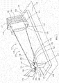
FIG. 1 is an exploded perspective view of a fixture with an article and resistance welding apparatus, according to an embodiment of the present disclosure. -
FIG. 2 is an assembled perspective view of the fixture, article and resistance welding apparatus ofFIG. 1 , according to an embodiment of the present disclosure. - Wherever possible, the same reference numbers will be used throughout the drawings to represent the same parts.
- Provided are exemplary fixtures and a methods for resistance welding of a pad to a surface. Embodiments of the present disclosure, in comparison to methods not utilizing one or more features disclosed herein, increase efficiency, reduce costs, reduce process time, increase joint strength, or a combination thereof.
- Referring to
FIGS. 1 and2 , in one embodiment, afixture 100 for resistance welding of at least onepad 106 to at least onesurface 104 of anarticle 102 includes afirst support element 108, asecond support element 114, and athird support element 120. Thefirst support element 108 includes afirst contact surface 110, thefirst support 108 element being adapted and disposed to support afirst portion 112 of thearticle 102, and thefirst contact surface 110 being inelastic and electrically insulating. Thesecond support element 114 includes asecond contact surface 116, thesecond support element 114 being adapted and disposed to support asecond portion 118 of thearticle 102, and thesecond contact surface 116 being inelastic and electrically insulating. Thethird support element 120 includes athird contact surface 122, thethird support element 120 being adapted and disposed to support athird portion 124 of thearticle 102, and thethird contact surface 122 being inelastic and electrically insulating. Thefixture 100 is arranged and disposed to non-rotatably cradle thearticle 102 with at least onesurface 104 of thearticle 102 accessible for placement of the at least onepad 106 on the at least onesurface 104 and the application of afirst electrode 128 of aresistance welding apparatus 126 to the at least onepad 106 and asecond electrode 130 of theresistance welding apparatus 126 to thearticle 102. - As used herein, "inelastic" indicates a material which does not exhibit any significant elasticity under the temperature and pressure conditions necessary for resistively welding the at least one
pad 106 to the at least onesurface 104. As used herein, "non-rotatably cradle" indicates that thefixture 100 maintains thearticle 102 in place without significant translational or rotational movement under the physical conditions generated by theresistance welding apparatus 126 resistively welding the at least onepad 106 to the at least onesurface 104. - In one embodiment, the
article 102 is aturbine component 132. Theturbine component 132 may be formed from any suitable material, including, but not limited to, superalloys, nickel- based superalloys, cobalt-based superalloys, or combinations thereof. In a further embodiment, theturbine component 132 is a shroudedturbine blade 134 including aroot 136, anairfoil 138, ablade shroud 140, and anangel wing 142. Theblade shroud 140 includes ashroud edge 144, and at least one interlockingnotch 146 having at least oneintershroud contact surface 148. The at least oneintershroud contact surface 148 is the at least onesurface 104. Thefirst portion 112 of thearticle 102 is theshroud edge 144, thesecond portion 118 of thearticle 102 is theroot 136, and thethird portion 124 of thearticle 102 is theangel wing 142. The at least onepad 106 is at least onecontact pad 150. - The at least one
pad 106 may include any suitable material, including, but not limited to, CM64, PWA 694, MTS 1087A, B50TF193, B50TF193S6, T800, or combinations thereof. In one embodiment, the at least onepad 106 includes a material having a diamond pyramid hardness of at least about 175 at 1,400 °F. The at least onepad 106 may be free of low melt alloys and binding agents. As used herein, "free of low melt alloys and binding agents" indicates that any low melt alloy or binding agent present, cumulatively, is beneath the threshold which would materially affect the physical properties of the at least onepad 106. In another embodiment, the at least onepad 106 is more resistive to abrasion than the at least onesurface 104 of thearticle 102. In yet another embodiment, the at least onepad 106 includes a thickness between about 0.005 inches and about 0.400 inches, alternatively between about 0.01 inches and about 0.35 inches, alternatively about 0.05 inches to about 0.30 inches, alternatively between about 0.10 inches to about 0.25 inches. - The
fixture 100 may be configurable for resistance welding of a first at least onepad 152 to afirst surface 154 of thearticle 102 and a second at least onepad 156 to a second at least onesurface 158 of thearticle 102. - In one embodiment, the
fixture 100 is arranged and disposed to position thearticle 102 with at least three distinct welding positions accessible on the at least onepad 106. - The
fixture 100 may include at least one point of contact with a supportingsurface 160. Thefixture 100 may further include at least four points of contact with the supportingsurface 160. - In one embodiment, a method for resistively welding at least one
pad 106 to at least onesurface 104 of anarticle 102 includes mounting thearticle 102 in thefixture 100, placing the at least onepad 106 on the at least onesurface 104 of thearticle 102, positioning afirst electrode 128 of aresistance welding apparatus 126 to the at least onepad 106 and asecond electrode 130 of theresistance welding apparatus 126 to thearticle 102, and applying pressure and electric current across the at least onepad 106 and the at least onesurface 104 of thearticle 102. Resistively welding the at least onepad 106 to the at least onesurface 104 may include resistively welding the at least onepad 106 to the at least onesurface 104 in at least three distinct locations. - In a further embodiment, mounting the
article 102 in thefixture 100 includes mounting a shroudedturbine blade 134 in thefixture 100. Placing the at least onepad 106 on the at least onesurface 104 of thearticle 102 may include placing the at least onepad 106 on at least oneintershroud contact surface 148 of the shroudedturbine blade 134. Mounting thearticle 102 in thefixture 100 may further include disposing ashroud edge 144 of the shroudedturbine blade 134 on thefirst contact surface 110 of thefirst support element 108, disposing aroot 136 of the shroudedturbine blade 134 on thesecond contact surface 116 of thesecond support element 114, and disposing anangel wing 142 of the shroudedturbine blade 134 on thethird contact surface 122 of thethird support element 120. - In another embodiment, a method for resistively welding a first at least one
pad 152 to a first at least onesurface 154 of anarticle 102 and a second at least onepad 156 to a second at least onesurface 158 of thearticle 102 includes mounting thearticle 102 in thefixture 100, placing the first at least onepad 152 on the first at least onesurface 154, positioning afirst electrode 128 of aresistance welding apparatus 126 to the first at least onepad 152 and asecond electrode 130 of theresistance welding apparatus 126 to thearticle 102, applying pressure and electric current across the first at least onepad 152 and the first at least onesurface 154, dismounting thearticle 102 from thefixture 100, rotating thearticle 102, remounting thearticle 102 in thefixture 100, placing the second at least onepad 156 on the second at least onesurface 158, positioning thefirst electrode 128 of theresistance welding apparatus 126 to the second at least onepad 156 and thesecond electrode 130 of theresistance welding apparatus 126 to thearticle 102, and applying pressure and electric current across the second at least onepad 156 and the second at least onesurface 158. Resistively welding the first at least onepad 152 to the first at least onesurface 154 may include resistively welding the first at least onepad 152 to the first at least onesurface 154 in at least three distinct locations. Resistively welding the second at least onepad 156 to the second at least onesurface 158 may include resistively welding the second at least onepad 156 to the second at least onesurface 158 in at least three distinct locations. The identification of the first at least onepad 152 and the first at least onesurface 154, and the second at least onepad 156 and the second at least onesurface 158, inFIGS. 1 and2 are for illustrative purposes only, and are considered to be interchangeable. - The
fixture 100 may be reconfigured from a first contract surface configuration to a second contact surface configuration to non-rotatably cradle thearticle 102 with the first at least onesurface 154 accessible for placement of the first at least onepad 152 on the first at least onesurface 154 and the application of thefirst electrode 128 to the first at least onepad 152 and thesecond electrode 130 to thearticle 102 prior to rotating thearticle 102, and to non-rotatably cradle thearticle 102 with the second at least onesurface 158 accessible for placement of the second at least onepad 156 on the second at least onesurface 158 and the application of thefirst electrode 128 to the second at least onepad 156 and thesecond electrode 130 to thearticle 102 after rotating thearticle 102. - While the invention has been described with reference to a preferred embodiment, it will be understood by those skilled in the art that various changes may be made and equivalents may be substituted for elements thereof without departing from the scope of the invention. In addition, many modifications may be made to adapt a particular situation or material to the teachings of the invention without departing from the essential scope thereof. Therefore, it is intended that the invention not be limited to the particular embodiment disclosed as the best mode contemplated for carrying out this invention, but that the invention will include all embodiments falling within the scope of the appended claims.
- Various aspects and embodiments of the present invention are defined by the following clauses:
- 1. A fixture for resistance welding of at least one contact pad to at least one intershroud contact surface of a shrouded turbine blade, the fixture comprising:
- a first support element having a first contact surface, the first support element being adapted and disposed to support a shroud edge of the shrouded turbine blade, and the first contact surface being inelastic and electrically insulating;
- a second support element having a second contact surface, the second support element being adapted and disposed to support a root of the shrouded turbine blade, and the second contact surface being inelastic and electrically insulating; and
- a third support element having a third contact surface, the third support element being adapted and disposed to support an angel wing of the shrouded turbine blade, and the third contact surface being inelastic and electrically insulating;
- wherein the fixture is arranged and disposed to non-rotatably cradle the shrouded turbine blade with the at least one intershroud contact surface accessible for placement of the at least one contact pad and application of a first electrode of a resistance welding apparatus to the at least one contact pad and a second electrode of the resistance welding apparatus to the shrouded turbine blade.
- 2. The fixture of clause 1, wherein the fixture is configurable for resistance welding of a first at least one contact pad to a first at least one intershroud contact surface of the shrouded turbine blade and a second at least one contact pad to a second at least one intershroud contact surface of the shrouded turbine blade.
- 3. The fixture of clause 1, wherein the fixture is arranged and disposed to position the shrouded turbine blade with at least three distinct welding positions accessible on the at least one contact pad.
- 4. The fixture of clause 1, wherein the fixture includes at least one point of contact with a supporting surface.
- 5. The fixture of clause 4, wherein the fixture includes at least four points of contact with the supporting surface.
- 6. A method for resistively welding at least one pad to at least one surface of an article, comprising:
- mounting the article in a fixture, the fixture including:
- a first support element having a first contact surface, the first support element being adapted and disposed to support a first portion of the article, and the first contact surface being inelastic and electrically insulating;
- a second support element having a second contact surface, the second support element being adapted and disposed to support a second portion of the article, and the second contact surface being inelastic and electrically insulating; and
- a third support element having a third contact surface, the third support element being adapted and disposed to support a third portion of the article, and the third contact surface being inelastic and electrically insulating;
- wherein the fixture is arranged and disposed to non-rotatably cradle the article;
- placing the at least one pad on the at least one surface of the article;
- positioning a first electrode of a resistance welding apparatus to the at least one pad and a second electrode of the resistance welding apparatus to the article; and
- applying pressure and electric current across the at least one pad and the at least one surface of the article.
- mounting the article in a fixture, the fixture including:
- 7. The method of clause 6, wherein mounting the article in the fixture includes mounting a shrouded turbine blade in the fixture.
- 8. The method of clause 7, wherein placing the at least one pad on the at least one surface of the article includes placing the at least one pad on at least one intershroud contact surface of the shrouded turbine blade.
- 9. The method of clause 7, wherein mounting the article in the fixture includes disposing a shroud edge of the shrouded turbine blade on the first contact surface of the first support element, disposing a root of the shrouded turbine blade on the second contact surface of the second support element, and disposing an angel wing of the shrouded turbine blade on the third contact surface of the third support element.
- 10. The method of clause 6, wherein placing the at least one pad on the at least one surface of the article includes placing at least one contact pad free of low melt alloys and binding agents on the at least one surface of the article, the at least one contact pad being more resistive to abrasion than the at least one surface of the article.
- 11. A method for resistively welding a first at least one contact pad to a first at least one intershroud contact surface of a shrouded turbine blade and a second at least one contact pad to a second at least one intershroud contact surface of the shrouded turbine blade, compnsmg:
- mounting the shrouded turbine blade in a fixture, the fixture including:
- a first support element having a first contact surface, the first support element being adapted and disposed to support a shroud edge of the shrouded turbine blade, and the first contact surface being inelastic and electrically insulating;
- a second support element having a second contact surface, the second support element being adapted and disposed to support a root of the shrouded turbine blade, and the second contact surface being inelastic and electrically insulating; and
- a third support element having a third contact surface, the third support element being adapted and disposed to support an angel wing of the shrouded turbine blade, and the third contact surface being inelastic and electrically insulating;
- wherein the fixture is arranged and disposed to non-rotatably cradle the shrouded turbine blade;
- placing the first at least one contact pad on the first at least one intershroud contact surface; positioning a first electrode of a resistance welding apparatus to the first at least one contact pad and a second electrode of the resistance welding apparatus to the shrouded turbine blade;
- applying pressure and electric current across the first at least one contact pad and the first at least one intershroud contact surface;
- dismounting the shrouded turbine blade from the fixture; rotating
- the shrouded turbine blade;
- remounting the shrouded turbine blade in the fixture;
- placing the second at least one contact pad on the second at least one intershroud contact surface;
- positioning the first electrode of the resistance welding apparatus to the second at least one contact pad and the second electrode of the resistance welding apparatus to the shrouded turbine blade; and
- applying pressure and electric current across the second at least one contact pad and the second at least one intershroud contact surface.
- mounting the shrouded turbine blade in a fixture, the fixture including:
- 12. The method of clause 11, further including reconfiguring the fixture from a first contract surface configuration to a second contact surface configuration.
- 13. The method of clause 11, further including resistively welding the first at least one contact pad to the first at least one intershroud contact surface in at least three distinct locations.
- 14. The method of clause 11, further including resistively welding the second at least one contact pad to the second at least one intershroud contact surface in at least three distinct locations.
- 15. The method of clause 11, wherein the first at least one contact pad is free of low melt alloys and binding agents.
- 16. The method of clause 11, wherein the second at least one contact pad is free of low melt alloys and binding agents.
- 17. The method of clause 11, wherein the first at least one contact pad is more resistive to abrasion than the first at least one intershroud contact surface.
- 18. The method of clause 11, wherein the second at least one contact pad is more resistive to abrasion than the second at least one intershroud contact surface.
- 19. The method of clause 11, wherein the first at least one contact pad includes a thickness between about 0.005 inches and about 0.400 inches.
- 20. The method of clause 11, wherein the second at least one contact pad includes a thickness between about 0.005 inches and about 0.400 inches.
Claims (10)
- A fixture (100) for resistance welding of at least one contact pad (150) to at least one intershroud contact surface (148) of a shrouded turbine blade (134), the fixture (100) comprising:a first support element (108) having a first contact surface (110), the first support element (108) being adapted and disposed to support a shroud edge (144) of the shrouded turbine blade (134), and the first contact surface (110) being inelastic and electrically insulating;a second support element (114) having a second contact surface (116), the second support element (114) being adapted and disposed to support a root (136) of the shrouded turbine blade (134), and the second contact surface (116) being inelastic and electrically insulating; anda third support element (120) having a third contact surface (122), the third support element (120) being adapted and disposed to support an angel wing (142) of the shrouded turbine blade (134), and the third contact surface (122) being inelastic and electrically insulating;wherein the fixture (100) is arranged and disposed to non-rotatably cradle the shrouded turbine blade (134) with the at least one intershroud contact surface (148) accessible for placement of the at least one contact pad (150) and application of a first electrode (128) of a resistance welding apparatus (126) to the at least one contact pad (150) and a second electrode (130) of the resistance welding apparatus (126) to the shrouded turbine blade (134).
- The fixture of claim 1, wherein the fixture (100) is configurable for resistance welding of a first at least one contact pad (152) to a first at least one intershroud contact surface (154) of the shrouded turbine blade (134) and a second at least one contact pad (156) to a second at least one intershroud contact surface (158) of the shrouded turbine blade (134).
- The fixture of claim 1, wherein the fixture (100) is arranged and disposed to position the shrouded turbine blade (134) with at least three distinct welding positions accessible on the at least one contact pad (150).
- A method for resistively welding at least one pad (106) to at least one surface (104) of an article (102), comprising:mounting the article (102) in a fixture (100), the fixture (100) including:a first support element (108) having a first contact surface (110), the first support element (108) being adapted and disposed to support a first portion (112) of the article (102), and the first contact surface (110) being inelastic and electrically insulating;a second support element (114) having a second contact surface (116),the second support element (114) being adapted and disposed to support a second portion (118) of the article (102), and the second contact surface (116) being inelastic and electrically insulating; anda third support element (120) having a third contact surface (122), the third support element (120) being adapted and disposed to support a third portion (124) of the article (102), and the third contact surface (122) being inelastic and electrically insulating;wherein the fixture (100) is arranged and disposed to non-rotatably cradle the article (102);placing the at least one pad (106) on the at least one surface (104) of the article (102);positioning a first electrode (128) of a resistance welding apparatus (126) to the at least one pad (106) and a second electrode (130) of the resistance welding apparatus (126) to the article (102); andapplying pressure and electric current across the at least one pad (106) and the at least one surface (104) of the article (102).
- The method of claim 4, wherein mounting the article (102) in the fixture (100) includes mounting a shrouded turbine blade (134) in the fixture (100).
- The method of claim 4 or 5, wherein placing the at least one pad (106) on the at least one surface (104) of the article (102) includes placing the at least one pad (106) on at least one intershroud contact surface (148) of the shrouded turbine blade (134).
- The method of claim 5, wherein mounting the article (102) in the fixture (100) includes disposing a shroud edge (144) of the shrouded turbine blade (134) on the first contact surface (110) of the first support element (108), disposing a root (136) of the shrouded turbine blade (134) on the second contact surface (116) of the second support element (114), and disposing an angel wing (142) of the shrouded turbine blade (134) on the third contact surface (122) of the third support element (120).
- The method of claim 4, wherein placing the at least one pad (106) on the at least one surface (104) of the article (102) includes placing at least one contact pad (150) free of low melt alloys and binding agents on the at least one surface (104) of the article (102), the at least one contact pad (150) being more resistive to abrasion than the at least one surface (104) of the article (102).
- A method for resistively welding a first at least one contact pad (152) to a first at least one intershroud contact surface (154) of a shrouded turbine blade (134) and a second at least one contact pad (156) to a second at least one intershroud contact surface (158) of the shrouded turbine blade (134), comprising:mounting the shrouded turbine blade (134) in a fixture (100), the fixture (100) including:a first support element (108) having a first contact surface (110), the first support element (108) being adapted and disposed to support a shroud edge (144) of the shrouded turbine blade (134), and the first contact surface (110) being inelastic and electrically insulating;a second support element (114) having a second contact surface (116), the second support element (114) being adapted and disposed to support a root (136) of the shrouded turbine blade (134), and the second contact surface (116) being inelastic and electrically insulating; anda third support element (120) having a third contact surface (122), the third support element (120) being adapted and disposed to support an angel wing (142) of the shrouded turbine blade (134), and the third contact surface (122) being inelastic and electrically insulating;wherein the fixture (100) is arranged and disposed to non-rotatably cradle the shrouded turbine blade (134);placing the first at least one contact pad (152) on the first at least one intershroud contact surface (154);positioning a first electrode (128) of a resistance welding apparatus (126) to the first at least one contact pad (152) and a second electrode (130) of the resistance welding apparatus (126) to the shrouded turbine blade (134);applying pressure and electric current across the first at least one contact pad (152) and the first at least one intershroud contact surface (154);dismounting the shrouded turbine blade (134) from the fixture (100);rotating the shrouded turbine blade (134);remounting the shrouded turbine blade (134) in the fixture (100);placing the second at least one contact pad (156) on the second at least one intershroud contact surface (158);positioning the first electrode (128) of the resistance welding apparatus (126) to the second at least one contact pad (156) and the second electrode (130) of the resistance welding apparatus (126) to the shrouded turbine blade (134); andapplying pressure and electric current across the second at least one contact pad (156) and the second at least one intershroud contact surface (158).
- The method of claim 9, further including reconfiguring the fixture (100) from a first contract surface configuration to a second contact surface configuration.
Applications Claiming Priority (1)
| Application Number | Priority Date | Filing Date | Title |
|---|---|---|---|
| US14/943,558 US10421147B2 (en) | 2015-11-17 | 2015-11-17 | Fixture and method for resistance welding of a pad to a surface |
Publications (3)
| Publication Number | Publication Date |
|---|---|
| EP3170617A2 true EP3170617A2 (en) | 2017-05-24 |
| EP3170617A3 EP3170617A3 (en) | 2017-08-09 |
| EP3170617B1 EP3170617B1 (en) | 2024-02-07 |
Family
ID=57348488
Family Applications (1)
| Application Number | Title | Priority Date | Filing Date |
|---|---|---|---|
| EP16199126.0A Active EP3170617B1 (en) | 2015-11-17 | 2016-11-16 | Method for resistance welding of a pad to a surface |
Country Status (4)
| Country | Link |
|---|---|
| US (1) | US10421147B2 (en) |
| EP (1) | EP3170617B1 (en) |
| JP (1) | JP7073038B2 (en) |
| CN (1) | CN106881524B (en) |
Cited By (1)
| Publication number | Priority date | Publication date | Assignee | Title |
|---|---|---|---|---|
| EP3542951A1 (en) * | 2018-03-22 | 2019-09-25 | United Technologies Corporation | Fan blade repair fixture and method of repair |
Families Citing this family (1)
| Publication number | Priority date | Publication date | Assignee | Title |
|---|---|---|---|---|
| GB2597507B (en) * | 2020-07-24 | 2022-08-31 | Rolls Royce Plc | A fixture for supporting a plurality of gas turbine engine components to be imaged |
Family Cites Families (15)
| Publication number | Priority date | Publication date | Assignee | Title |
|---|---|---|---|---|
| US3331166A (en) * | 1964-11-27 | 1967-07-18 | Brenning Albert | Jig for grinding turbine blades of jet engines |
| US5097109A (en) * | 1990-02-20 | 1992-03-17 | General Motors Corporation | Insulated aluminum weld fixture and a method of making same |
| US5289897A (en) | 1992-10-22 | 1994-03-01 | Wiehe Jr William H | Sawbuck including vierendeel truss construction |
| US6186867B1 (en) * | 1996-04-30 | 2001-02-13 | United Technologies Corporation | Method for manufacturing precisely shaped parts |
| US6068541A (en) * | 1997-12-22 | 2000-05-30 | United Technologies Corporation | Method for using a fixture enabling more accurate machining of a part |
| US6164916A (en) * | 1998-11-02 | 2000-12-26 | General Electric Company | Method of applying wear-resistant materials to turbine blades, and turbine blades having wear-resistant materials |
| JP3909810B2 (en) | 2001-05-31 | 2007-04-25 | 株式会社東芝 | Material deterioration and damage recovery method for prime mover parts |
| JP2003097215A (en) * | 2001-09-19 | 2003-04-03 | Mitsubishi Heavy Ind Ltd | Blade structure for turbine rotor and turbo machine |
| US7222422B2 (en) | 2004-02-16 | 2007-05-29 | General Electric Company | Method for refurbishing surfaces subjected to high compression contact |
| CN101146652B (en) | 2005-03-09 | 2010-04-21 | 株式会社Ihi | Jig |
| US7762004B2 (en) * | 2007-01-31 | 2010-07-27 | General Electric Company | Inspection tool for measuring bucket Z notch position |
| US8887390B2 (en) * | 2008-08-15 | 2014-11-18 | Dresser-Rand Company | Method for correcting downstream deflection in gas turbine nozzles |
| AT512063B1 (en) * | 2011-10-31 | 2016-01-15 | Fronius Int Gmbh | POWER SOURCE AND METHOD FOR COOLING SUCH A POWER SOURCE |
| CN103341687B (en) * | 2013-07-12 | 2015-08-26 | 苏州斯奥克微电机制造有限公司 | Blade is welded on epitrochanterian welding tooling by one |
| DE102014224156B4 (en) * | 2014-11-26 | 2024-05-23 | MTU Aero Engines AG | Soldering process for armouring the Z-notch of TIAL blades and component of a turbomachine with such armouring |
-
2015
- 2015-11-17 US US14/943,558 patent/US10421147B2/en active Active
-
2016
- 2016-11-09 JP JP2016218489A patent/JP7073038B2/en active Active
- 2016-11-16 EP EP16199126.0A patent/EP3170617B1/en active Active
- 2016-11-17 CN CN201611011772.0A patent/CN106881524B/en active Active
Non-Patent Citations (1)
| Title |
|---|
| None |
Cited By (2)
| Publication number | Priority date | Publication date | Assignee | Title |
|---|---|---|---|---|
| EP3542951A1 (en) * | 2018-03-22 | 2019-09-25 | United Technologies Corporation | Fan blade repair fixture and method of repair |
| US10711611B2 (en) | 2018-03-22 | 2020-07-14 | Raytheon Technologies Corporation | Fan blade repair fixture and method of repair |
Also Published As
| Publication number | Publication date |
|---|---|
| CN106881524A (en) | 2017-06-23 |
| CN106881524B (en) | 2020-11-03 |
| EP3170617B1 (en) | 2024-02-07 |
| JP2017096271A (en) | 2017-06-01 |
| JP7073038B2 (en) | 2022-05-23 |
| US10421147B2 (en) | 2019-09-24 |
| EP3170617A3 (en) | 2017-08-09 |
| US20170136569A1 (en) | 2017-05-18 |
Similar Documents
| Publication | Publication Date | Title |
|---|---|---|
| US9126287B2 (en) | Advanced pass progression for build-up welding | |
| US10369593B2 (en) | Method of applying a nanocrystalline coating to a gas turbine engine component | |
| JP2008045541A (en) | Method of repairing shroud of turbine blades | |
| US8142161B2 (en) | Replaceable staking insert | |
| US9488053B2 (en) | Method for repairing a single crystal turbine blade | |
| EP2551459A3 (en) | Cap for ceramic blade tip shroud | |
| GB0412775D0 (en) | Method of replacing damaged aerofoil | |
| EP2159371B1 (en) | Gas turbine airfoil assemblies and methods of repair | |
| EP2848356B1 (en) | A method for repairing a turbine component wherein damaged material is removed and a plug with improved material properties is inserted and a corresponding repaired component | |
| EP2781697A1 (en) | A turbomachine component with a stress relief cavity and method of forming such a cavity | |
| US9500080B2 (en) | Method of replacing damaged aerofoil | |
| US20180347380A1 (en) | Removable anti-wear part for blade root | |
| US10421147B2 (en) | Fixture and method for resistance welding of a pad to a surface | |
| US20060245916A1 (en) | Stator blades, turbomachines comprising such blades and method of repairing such blades | |
| EP2971563A2 (en) | Component repair using brazed surface textured superalloy foil | |
| CN1824840B (en) | Method for repairing a rubbing surface of a turbomachine variable-pitch blade | |
| EP2256300A3 (en) | Knife edge seal assembly and corresponding rotor stage | |
| JP6612093B2 (en) | System and method for repairing blades | |
| WO2017123524A1 (en) | Methods for mounting a turbine subcomponent to a turbine component | |
| JP2007182885A (en) | Abrasion preventive device for guide pivot of variable-pitch vane of compressor of turbomachine | |
| US8721292B2 (en) | Gas-turbine blade root | |
| EP2022597A1 (en) | Methods for repairing gas turbine engine knife edge seals | |
| WO2020032964A1 (en) | Friction stir additive manufacturing and repair of turbine components | |
| US20150368786A1 (en) | Metallic coating fixed stator tip treatment | |
| US10100651B2 (en) | Wear resistance of a high-temperature component imparted by a cobalt coating |
Legal Events
| Date | Code | Title | Description |
|---|---|---|---|
| PUAI | Public reference made under article 153(3) epc to a published international application that has entered the european phase |
Free format text: ORIGINAL CODE: 0009012 |
|
| STAA | Information on the status of an ep patent application or granted ep patent |
Free format text: STATUS: THE APPLICATION HAS BEEN PUBLISHED |
|
| AK | Designated contracting states |
Kind code of ref document: A2 Designated state(s): AL AT BE BG CH CY CZ DE DK EE ES FI FR GB GR HR HU IE IS IT LI LT LU LV MC MK MT NL NO PL PT RO RS SE SI SK SM TR |
|
| AX | Request for extension of the european patent |
Extension state: BA ME |
|
| PUAL | Search report despatched |
Free format text: ORIGINAL CODE: 0009013 |
|
| AK | Designated contracting states |
Kind code of ref document: A3 Designated state(s): AL AT BE BG CH CY CZ DE DK EE ES FI FR GB GR HR HU IE IS IT LI LT LU LV MC MK MT NL NO PL PT RO RS SE SI SK SM TR |
|
| AX | Request for extension of the european patent |
Extension state: BA ME |
|
| RIC1 | Information provided on ipc code assigned before grant |
Ipc: B23K 11/00 20060101ALI20170704BHEP Ipc: B23K 37/04 20060101AFI20170704BHEP Ipc: B23K 11/11 20060101ALI20170704BHEP |
|
| STAA | Information on the status of an ep patent application or granted ep patent |
Free format text: STATUS: REQUEST FOR EXAMINATION WAS MADE |
|
| 17P | Request for examination filed |
Effective date: 20180209 |
|
| RBV | Designated contracting states (corrected) |
Designated state(s): AL AT BE BG CH CY CZ DE DK EE ES FI FR GB GR HR HU IE IS IT LI LT LU LV MC MK MT NL NO PL PT RO RS SE SI SK SM TR |
|
| STAA | Information on the status of an ep patent application or granted ep patent |
Free format text: STATUS: EXAMINATION IS IN PROGRESS |
|
| 17Q | First examination report despatched |
Effective date: 20200121 |
|
| GRAP | Despatch of communication of intention to grant a patent |
Free format text: ORIGINAL CODE: EPIDOSNIGR1 |
|
| STAA | Information on the status of an ep patent application or granted ep patent |
Free format text: STATUS: GRANT OF PATENT IS INTENDED |
|
| INTG | Intention to grant announced |
Effective date: 20231031 |
|
| RAP1 | Party data changed (applicant data changed or rights of an application transferred) |
Owner name: GENERAL ELECTRIC TECHNOLOGY GMBH |
|
| GRAS | Grant fee paid |
Free format text: ORIGINAL CODE: EPIDOSNIGR3 |
|
| GRAA | (expected) grant |
Free format text: ORIGINAL CODE: 0009210 |
|
| STAA | Information on the status of an ep patent application or granted ep patent |
Free format text: STATUS: THE PATENT HAS BEEN GRANTED |
|
| AK | Designated contracting states |
Kind code of ref document: B1 Designated state(s): AL AT BE BG CH CY CZ DE DK EE ES FI FR GB GR HR HU IE IS IT LI LT LU LV MC MK MT NL NO PL PT RO RS SE SI SK SM TR |
|
| REG | Reference to a national code |
Ref country code: GB Ref legal event code: FG4D |
|
| REG | Reference to a national code |
Ref country code: CH Ref legal event code: EP |
|
| REG | Reference to a national code |
Ref country code: DE Ref legal event code: R096 Ref document number: 602016085651 Country of ref document: DE |
|
| REG | Reference to a national code |
Ref country code: IE Ref legal event code: FG4D |
|
| REG | Reference to a national code |
Ref country code: LT Ref legal event code: MG9D |
|
| REG | Reference to a national code |
Ref country code: NL Ref legal event code: MP Effective date: 20240207 |
|
| PG25 | Lapsed in a contracting state [announced via postgrant information from national office to epo] |
Ref country code: IS Free format text: LAPSE BECAUSE OF FAILURE TO SUBMIT A TRANSLATION OF THE DESCRIPTION OR TO PAY THE FEE WITHIN THE PRESCRIBED TIME-LIMIT Effective date: 20240607 |
|
| PG25 | Lapsed in a contracting state [announced via postgrant information from national office to epo] |
Ref country code: LT Free format text: LAPSE BECAUSE OF FAILURE TO SUBMIT A TRANSLATION OF THE DESCRIPTION OR TO PAY THE FEE WITHIN THE PRESCRIBED TIME-LIMIT Effective date: 20240207 |
|
| PG25 | Lapsed in a contracting state [announced via postgrant information from national office to epo] |
Ref country code: GR Free format text: LAPSE BECAUSE OF FAILURE TO SUBMIT A TRANSLATION OF THE DESCRIPTION OR TO PAY THE FEE WITHIN THE PRESCRIBED TIME-LIMIT Effective date: 20240508 |
|
| REG | Reference to a national code |
Ref country code: AT Ref legal event code: MK05 Ref document number: 1655065 Country of ref document: AT Kind code of ref document: T Effective date: 20240207 |
|
| PG25 | Lapsed in a contracting state [announced via postgrant information from national office to epo] |
Ref country code: RS Free format text: LAPSE BECAUSE OF FAILURE TO SUBMIT A TRANSLATION OF THE DESCRIPTION OR TO PAY THE FEE WITHIN THE PRESCRIBED TIME-LIMIT Effective date: 20240507 Ref country code: NL Free format text: LAPSE BECAUSE OF FAILURE TO SUBMIT A TRANSLATION OF THE DESCRIPTION OR TO PAY THE FEE WITHIN THE PRESCRIBED TIME-LIMIT Effective date: 20240207 Ref country code: HR Free format text: LAPSE BECAUSE OF FAILURE TO SUBMIT A TRANSLATION OF THE DESCRIPTION OR TO PAY THE FEE WITHIN THE PRESCRIBED TIME-LIMIT Effective date: 20240207 |
|
| PG25 | Lapsed in a contracting state [announced via postgrant information from national office to epo] |
Ref country code: ES Free format text: LAPSE BECAUSE OF FAILURE TO SUBMIT A TRANSLATION OF THE DESCRIPTION OR TO PAY THE FEE WITHIN THE PRESCRIBED TIME-LIMIT Effective date: 20240207 |
|
| PG25 | Lapsed in a contracting state [announced via postgrant information from national office to epo] |
Ref country code: AT Free format text: LAPSE BECAUSE OF FAILURE TO SUBMIT A TRANSLATION OF THE DESCRIPTION OR TO PAY THE FEE WITHIN THE PRESCRIBED TIME-LIMIT Effective date: 20240207 |
|
| PG25 | Lapsed in a contracting state [announced via postgrant information from national office to epo] |
Ref country code: RS Free format text: LAPSE BECAUSE OF FAILURE TO SUBMIT A TRANSLATION OF THE DESCRIPTION OR TO PAY THE FEE WITHIN THE PRESCRIBED TIME-LIMIT Effective date: 20240507 Ref country code: NO Free format text: LAPSE BECAUSE OF FAILURE TO SUBMIT A TRANSLATION OF THE DESCRIPTION OR TO PAY THE FEE WITHIN THE PRESCRIBED TIME-LIMIT Effective date: 20240507 Ref country code: NL Free format text: LAPSE BECAUSE OF FAILURE TO SUBMIT A TRANSLATION OF THE DESCRIPTION OR TO PAY THE FEE WITHIN THE PRESCRIBED TIME-LIMIT Effective date: 20240207 Ref country code: LT Free format text: LAPSE BECAUSE OF FAILURE TO SUBMIT A TRANSLATION OF THE DESCRIPTION OR TO PAY THE FEE WITHIN THE PRESCRIBED TIME-LIMIT Effective date: 20240207 Ref country code: IS Free format text: LAPSE BECAUSE OF FAILURE TO SUBMIT A TRANSLATION OF THE DESCRIPTION OR TO PAY THE FEE WITHIN THE PRESCRIBED TIME-LIMIT Effective date: 20240607 Ref country code: HR Free format text: LAPSE BECAUSE OF FAILURE TO SUBMIT A TRANSLATION OF THE DESCRIPTION OR TO PAY THE FEE WITHIN THE PRESCRIBED TIME-LIMIT Effective date: 20240207 Ref country code: GR Free format text: LAPSE BECAUSE OF FAILURE TO SUBMIT A TRANSLATION OF THE DESCRIPTION OR TO PAY THE FEE WITHIN THE PRESCRIBED TIME-LIMIT Effective date: 20240508 Ref country code: FI Free format text: LAPSE BECAUSE OF FAILURE TO SUBMIT A TRANSLATION OF THE DESCRIPTION OR TO PAY THE FEE WITHIN THE PRESCRIBED TIME-LIMIT Effective date: 20240207 Ref country code: ES Free format text: LAPSE BECAUSE OF FAILURE TO SUBMIT A TRANSLATION OF THE DESCRIPTION OR TO PAY THE FEE WITHIN THE PRESCRIBED TIME-LIMIT Effective date: 20240207 Ref country code: BG Free format text: LAPSE BECAUSE OF FAILURE TO SUBMIT A TRANSLATION OF THE DESCRIPTION OR TO PAY THE FEE WITHIN THE PRESCRIBED TIME-LIMIT Effective date: 20240207 Ref country code: AT Free format text: LAPSE BECAUSE OF FAILURE TO SUBMIT A TRANSLATION OF THE DESCRIPTION OR TO PAY THE FEE WITHIN THE PRESCRIBED TIME-LIMIT Effective date: 20240207 |
|
| PG25 | Lapsed in a contracting state [announced via postgrant information from national office to epo] |
Ref country code: PT Free format text: LAPSE BECAUSE OF FAILURE TO SUBMIT A TRANSLATION OF THE DESCRIPTION OR TO PAY THE FEE WITHIN THE PRESCRIBED TIME-LIMIT Effective date: 20240607 Ref country code: PL Free format text: LAPSE BECAUSE OF FAILURE TO SUBMIT A TRANSLATION OF THE DESCRIPTION OR TO PAY THE FEE WITHIN THE PRESCRIBED TIME-LIMIT Effective date: 20240207 |
|
| PG25 | Lapsed in a contracting state [announced via postgrant information from national office to epo] |
Ref country code: SE Free format text: LAPSE BECAUSE OF FAILURE TO SUBMIT A TRANSLATION OF THE DESCRIPTION OR TO PAY THE FEE WITHIN THE PRESCRIBED TIME-LIMIT Effective date: 20240207 Ref country code: PT Free format text: LAPSE BECAUSE OF FAILURE TO SUBMIT A TRANSLATION OF THE DESCRIPTION OR TO PAY THE FEE WITHIN THE PRESCRIBED TIME-LIMIT Effective date: 20240607 Ref country code: PL Free format text: LAPSE BECAUSE OF FAILURE TO SUBMIT A TRANSLATION OF THE DESCRIPTION OR TO PAY THE FEE WITHIN THE PRESCRIBED TIME-LIMIT Effective date: 20240207 Ref country code: LV Free format text: LAPSE BECAUSE OF FAILURE TO SUBMIT A TRANSLATION OF THE DESCRIPTION OR TO PAY THE FEE WITHIN THE PRESCRIBED TIME-LIMIT Effective date: 20240207 |
|
| PG25 | Lapsed in a contracting state [announced via postgrant information from national office to epo] |
Ref country code: DK Free format text: LAPSE BECAUSE OF FAILURE TO SUBMIT A TRANSLATION OF THE DESCRIPTION OR TO PAY THE FEE WITHIN THE PRESCRIBED TIME-LIMIT Effective date: 20240207 |
|
| PG25 | Lapsed in a contracting state [announced via postgrant information from national office to epo] |
Ref country code: SM Free format text: LAPSE BECAUSE OF FAILURE TO SUBMIT A TRANSLATION OF THE DESCRIPTION OR TO PAY THE FEE WITHIN THE PRESCRIBED TIME-LIMIT Effective date: 20240207 |
|
| PG25 | Lapsed in a contracting state [announced via postgrant information from national office to epo] |
Ref country code: CZ Free format text: LAPSE BECAUSE OF FAILURE TO SUBMIT A TRANSLATION OF THE DESCRIPTION OR TO PAY THE FEE WITHIN THE PRESCRIBED TIME-LIMIT Effective date: 20240207 Ref country code: EE Free format text: LAPSE BECAUSE OF FAILURE TO SUBMIT A TRANSLATION OF THE DESCRIPTION OR TO PAY THE FEE WITHIN THE PRESCRIBED TIME-LIMIT Effective date: 20240207 |
|
| PG25 | Lapsed in a contracting state [announced via postgrant information from national office to epo] |
Ref country code: SK Free format text: LAPSE BECAUSE OF FAILURE TO SUBMIT A TRANSLATION OF THE DESCRIPTION OR TO PAY THE FEE WITHIN THE PRESCRIBED TIME-LIMIT Effective date: 20240207 |
|
| PG25 | Lapsed in a contracting state [announced via postgrant information from national office to epo] |
Ref country code: SM Free format text: LAPSE BECAUSE OF FAILURE TO SUBMIT A TRANSLATION OF THE DESCRIPTION OR TO PAY THE FEE WITHIN THE PRESCRIBED TIME-LIMIT Effective date: 20240207 Ref country code: SK Free format text: LAPSE BECAUSE OF FAILURE TO SUBMIT A TRANSLATION OF THE DESCRIPTION OR TO PAY THE FEE WITHIN THE PRESCRIBED TIME-LIMIT Effective date: 20240207 Ref country code: RO Free format text: LAPSE BECAUSE OF FAILURE TO SUBMIT A TRANSLATION OF THE DESCRIPTION OR TO PAY THE FEE WITHIN THE PRESCRIBED TIME-LIMIT Effective date: 20240207 Ref country code: EE Free format text: LAPSE BECAUSE OF FAILURE TO SUBMIT A TRANSLATION OF THE DESCRIPTION OR TO PAY THE FEE WITHIN THE PRESCRIBED TIME-LIMIT Effective date: 20240207 Ref country code: DK Free format text: LAPSE BECAUSE OF FAILURE TO SUBMIT A TRANSLATION OF THE DESCRIPTION OR TO PAY THE FEE WITHIN THE PRESCRIBED TIME-LIMIT Effective date: 20240207 Ref country code: CZ Free format text: LAPSE BECAUSE OF FAILURE TO SUBMIT A TRANSLATION OF THE DESCRIPTION OR TO PAY THE FEE WITHIN THE PRESCRIBED TIME-LIMIT Effective date: 20240207 |
|
| REG | Reference to a national code |
Ref country code: DE Ref legal event code: R097 Ref document number: 602016085651 Country of ref document: DE |
|
| PLBE | No opposition filed within time limit |
Free format text: ORIGINAL CODE: 0009261 |
|
| STAA | Information on the status of an ep patent application or granted ep patent |
Free format text: STATUS: NO OPPOSITION FILED WITHIN TIME LIMIT |
|
| 26N | No opposition filed |
Effective date: 20241108 |
|
| PG25 | Lapsed in a contracting state [announced via postgrant information from national office to epo] |
Ref country code: SI Free format text: LAPSE BECAUSE OF FAILURE TO SUBMIT A TRANSLATION OF THE DESCRIPTION OR TO PAY THE FEE WITHIN THE PRESCRIBED TIME-LIMIT Effective date: 20240207 |
|
| REG | Reference to a national code |
Ref country code: CH Ref legal event code: PL |
|
| PG25 | Lapsed in a contracting state [announced via postgrant information from national office to epo] |
Ref country code: MC Free format text: LAPSE BECAUSE OF FAILURE TO SUBMIT A TRANSLATION OF THE DESCRIPTION OR TO PAY THE FEE WITHIN THE PRESCRIBED TIME-LIMIT Effective date: 20240207 |
|
| PG25 | Lapsed in a contracting state [announced via postgrant information from national office to epo] |
Ref country code: LU Free format text: LAPSE BECAUSE OF NON-PAYMENT OF DUE FEES Effective date: 20241116 |
|
| REG | Reference to a national code |
Ref country code: CH Ref legal event code: PL |
|
| PG25 | Lapsed in a contracting state [announced via postgrant information from national office to epo] |
Ref country code: CH Free format text: LAPSE BECAUSE OF NON-PAYMENT OF DUE FEES Effective date: 20241130 |
|
| REG | Reference to a national code |
Ref country code: BE Ref legal event code: MM Effective date: 20241130 |
|
| PG25 | Lapsed in a contracting state [announced via postgrant information from national office to epo] |
Ref country code: BE Free format text: LAPSE BECAUSE OF NON-PAYMENT OF DUE FEES Effective date: 20241130 |
|
| PG25 | Lapsed in a contracting state [announced via postgrant information from national office to epo] |
Ref country code: IE Free format text: LAPSE BECAUSE OF NON-PAYMENT OF DUE FEES Effective date: 20241116 |
|
| PGFP | Annual fee paid to national office [announced via postgrant information from national office to epo] |
Ref country code: DE Payment date: 20251022 Year of fee payment: 10 |
|
| PGFP | Annual fee paid to national office [announced via postgrant information from national office to epo] |
Ref country code: GB Payment date: 20251023 Year of fee payment: 10 |
|
| PGFP | Annual fee paid to national office [announced via postgrant information from national office to epo] |
Ref country code: IT Payment date: 20251022 Year of fee payment: 10 |
|
| PGFP | Annual fee paid to national office [announced via postgrant information from national office to epo] |
Ref country code: FR Payment date: 20251022 Year of fee payment: 10 |
|
| PG25 | Lapsed in a contracting state [announced via postgrant information from national office to epo] |
Ref country code: HU Free format text: LAPSE BECAUSE OF FAILURE TO SUBMIT A TRANSLATION OF THE DESCRIPTION OR TO PAY THE FEE WITHIN THE PRESCRIBED TIME-LIMIT; INVALID AB INITIO Effective date: 20161116 |
|
| PG25 | Lapsed in a contracting state [announced via postgrant information from national office to epo] |
Ref country code: CY Free format text: LAPSE BECAUSE OF FAILURE TO SUBMIT A TRANSLATION OF THE DESCRIPTION OR TO PAY THE FEE WITHIN THE PRESCRIBED TIME-LIMIT; INVALID AB INITIO Effective date: 20161116 |