EP3170468A1 - Liquid delivery device and treatment device - Google Patents
Liquid delivery device and treatment device Download PDFInfo
- Publication number
- EP3170468A1 EP3170468A1 EP15822824.7A EP15822824A EP3170468A1 EP 3170468 A1 EP3170468 A1 EP 3170468A1 EP 15822824 A EP15822824 A EP 15822824A EP 3170468 A1 EP3170468 A1 EP 3170468A1
- Authority
- EP
- European Patent Office
- Prior art keywords
- section
- liquid
- liquid feeder
- handle
- distal end
- Prior art date
- Legal status (The legal status is an assumption and is not a legal conclusion. Google has not performed a legal analysis and makes no representation as to the accuracy of the status listed.)
- Withdrawn
Links
- 239000007788 liquid Substances 0.000 title claims abstract description 225
- 239000000523 sample Substances 0.000 claims description 66
- 238000001356 surgical procedure Methods 0.000 description 91
- 230000004048 modification Effects 0.000 description 33
- 238000012986 modification Methods 0.000 description 33
- 239000000463 material Substances 0.000 description 8
- 239000002504 physiological saline solution Substances 0.000 description 8
- 238000004804 winding Methods 0.000 description 7
- 239000004020 conductor Substances 0.000 description 3
- 239000000853 adhesive Substances 0.000 description 2
- 230000001070 adhesive effect Effects 0.000 description 2
- 239000012636 effector Substances 0.000 description 2
- 239000012530 fluid Substances 0.000 description 2
- 239000000314 lubricant Substances 0.000 description 2
- 239000007769 metal material Substances 0.000 description 2
- 239000004033 plastic Substances 0.000 description 2
- XLYOFNOQVPJJNP-UHFFFAOYSA-N water Substances O XLYOFNOQVPJJNP-UHFFFAOYSA-N 0.000 description 2
- 229910001069 Ti alloy Inorganic materials 0.000 description 1
- 210000004204 blood vessel Anatomy 0.000 description 1
- 230000015271 coagulation Effects 0.000 description 1
- 238000005345 coagulation Methods 0.000 description 1
- 230000005484 gravity Effects 0.000 description 1
- WABPQHHGFIMREM-UHFFFAOYSA-N lead(0) Chemical compound [Pb] WABPQHHGFIMREM-UHFFFAOYSA-N 0.000 description 1
- 239000002184 metal Substances 0.000 description 1
- 229910052751 metal Inorganic materials 0.000 description 1
- 239000004810 polytetrafluoroethylene Substances 0.000 description 1
- 229920001343 polytetrafluoroethylene Polymers 0.000 description 1
Images






Classifications
-
- A—HUMAN NECESSITIES
- A61—MEDICAL OR VETERINARY SCIENCE; HYGIENE
- A61B—DIAGNOSIS; SURGERY; IDENTIFICATION
- A61B18/00—Surgical instruments, devices or methods for transferring non-mechanical forms of energy to or from the body
- A61B18/04—Surgical instruments, devices or methods for transferring non-mechanical forms of energy to or from the body by heating
- A61B18/12—Surgical instruments, devices or methods for transferring non-mechanical forms of energy to or from the body by heating by passing a current through the tissue to be heated, e.g. high-frequency current
- A61B18/14—Probes or electrodes therefor
- A61B18/1442—Probes having pivoting end effectors, e.g. forceps
- A61B18/1445—Probes having pivoting end effectors, e.g. forceps at the distal end of a shaft, e.g. forceps or scissors at the end of a rigid rod
-
- A—HUMAN NECESSITIES
- A61—MEDICAL OR VETERINARY SCIENCE; HYGIENE
- A61B—DIAGNOSIS; SURGERY; IDENTIFICATION
- A61B17/00—Surgical instruments, devices or methods
- A61B17/32—Surgical cutting instruments
- A61B17/320068—Surgical cutting instruments using mechanical vibrations, e.g. ultrasonic
- A61B17/320092—Surgical cutting instruments using mechanical vibrations, e.g. ultrasonic with additional movable means for clamping or cutting tissue, e.g. with a pivoting jaw
-
- A—HUMAN NECESSITIES
- A61—MEDICAL OR VETERINARY SCIENCE; HYGIENE
- A61B—DIAGNOSIS; SURGERY; IDENTIFICATION
- A61B17/00—Surgical instruments, devices or methods
- A61B17/28—Surgical forceps
- A61B17/29—Forceps for use in minimally invasive surgery
- A61B2017/2926—Details of heads or jaws
- A61B2017/2927—Details of heads or jaws the angular position of the head being adjustable with respect to the shaft
- A61B2017/2929—Details of heads or jaws the angular position of the head being adjustable with respect to the shaft with a head rotatable about the longitudinal axis of the shaft
-
- A—HUMAN NECESSITIES
- A61—MEDICAL OR VETERINARY SCIENCE; HYGIENE
- A61B—DIAGNOSIS; SURGERY; IDENTIFICATION
- A61B17/00—Surgical instruments, devices or methods
- A61B17/32—Surgical cutting instruments
- A61B17/320068—Surgical cutting instruments using mechanical vibrations, e.g. ultrasonic
- A61B2017/320069—Surgical cutting instruments using mechanical vibrations, e.g. ultrasonic for ablating tissue
-
- A—HUMAN NECESSITIES
- A61—MEDICAL OR VETERINARY SCIENCE; HYGIENE
- A61B—DIAGNOSIS; SURGERY; IDENTIFICATION
- A61B17/00—Surgical instruments, devices or methods
- A61B17/32—Surgical cutting instruments
- A61B17/320068—Surgical cutting instruments using mechanical vibrations, e.g. ultrasonic
- A61B2017/320084—Irrigation sleeves
-
- A—HUMAN NECESSITIES
- A61—MEDICAL OR VETERINARY SCIENCE; HYGIENE
- A61B—DIAGNOSIS; SURGERY; IDENTIFICATION
- A61B17/00—Surgical instruments, devices or methods
- A61B17/32—Surgical cutting instruments
- A61B17/320068—Surgical cutting instruments using mechanical vibrations, e.g. ultrasonic
- A61B17/320092—Surgical cutting instruments using mechanical vibrations, e.g. ultrasonic with additional movable means for clamping or cutting tissue, e.g. with a pivoting jaw
- A61B2017/320094—Surgical cutting instruments using mechanical vibrations, e.g. ultrasonic with additional movable means for clamping or cutting tissue, e.g. with a pivoting jaw additional movable means performing clamping operation
-
- A—HUMAN NECESSITIES
- A61—MEDICAL OR VETERINARY SCIENCE; HYGIENE
- A61B—DIAGNOSIS; SURGERY; IDENTIFICATION
- A61B17/00—Surgical instruments, devices or methods
- A61B17/32—Surgical cutting instruments
- A61B17/320068—Surgical cutting instruments using mechanical vibrations, e.g. ultrasonic
- A61B17/320092—Surgical cutting instruments using mechanical vibrations, e.g. ultrasonic with additional movable means for clamping or cutting tissue, e.g. with a pivoting jaw
- A61B2017/320095—Surgical cutting instruments using mechanical vibrations, e.g. ultrasonic with additional movable means for clamping or cutting tissue, e.g. with a pivoting jaw with sealing or cauterizing means
-
- A—HUMAN NECESSITIES
- A61—MEDICAL OR VETERINARY SCIENCE; HYGIENE
- A61B—DIAGNOSIS; SURGERY; IDENTIFICATION
- A61B18/00—Surgical instruments, devices or methods for transferring non-mechanical forms of energy to or from the body
- A61B2018/00005—Cooling or heating of the probe or tissue immediately surrounding the probe
- A61B2018/00011—Cooling or heating of the probe or tissue immediately surrounding the probe with fluids
- A61B2018/00029—Cooling or heating of the probe or tissue immediately surrounding the probe with fluids open
-
- A—HUMAN NECESSITIES
- A61—MEDICAL OR VETERINARY SCIENCE; HYGIENE
- A61B—DIAGNOSIS; SURGERY; IDENTIFICATION
- A61B18/00—Surgical instruments, devices or methods for transferring non-mechanical forms of energy to or from the body
- A61B2018/00994—Surgical instruments, devices or methods for transferring non-mechanical forms of energy to or from the body combining two or more different kinds of non-mechanical energy or combining one or more non-mechanical energies with ultrasound
-
- A—HUMAN NECESSITIES
- A61—MEDICAL OR VETERINARY SCIENCE; HYGIENE
- A61B—DIAGNOSIS; SURGERY; IDENTIFICATION
- A61B2218/00—Details of surgical instruments, devices or methods for transferring non-mechanical forms of energy to or from the body
- A61B2218/001—Details of surgical instruments, devices or methods for transferring non-mechanical forms of energy to or from the body having means for irrigation and/or aspiration of substances to and/or from the surgical site
- A61B2218/002—Irrigation
Definitions
- This invention relates to a liquid feeder mounted on a treatment instrument, and a treatment apparatus including the liquid feeder and the treatment instrument.
- U.S. Patent Application Publication No. 2006/0265035 discloses a treatment instrument for treating a tissue by an ultrasonic vibration.
- This treatment instrument can rotate a sheath unit (long member) by the rotation of a knob.
- this treatment instrument can externally attach/detach, to/from the sheath unit, a liquid feeder capable of supplying a liquid such as physiological saline to a treatment section (the distal end of the sheath unit) through a liquid feed tube.
- a tube connected to the liquid feeder to supply a liquid may tend to wind about the handle unit, ultrasonic transducer unit, sheath unit, or the like of the treatment instrument.
- the present invention has as its object to provide a liquid feeder capable of preventing, when a user appropriately rotates a sheath unit while grasping a handle unit, a tube (liquid feed channel) for supplying a liquid from winding about the handle unit or a member mounted on it, and a treatment apparatus including the liquid feeder.
- a liquid feeder mounted on a treatment instrument includes: a main tube that is arranged along a long member of the treatment instrument in which a longitudinal axis is defined and that is configured to flow a liquid to an outer circumference of the long member; a connection section that is arranged on a proximal end side of the main tube along the longitudinal axis and that is configured to connect an interior of the main tube and an interior of a liquid feed channel from a liquid source; and a fixing section that is arranged in the connection section and that is configured to fix the connection section to a handle unit arranged at a proximal end of the long member and grasped by a user.
- the first embodiment will be described with reference to FIGS. 1A to 6 .
- a surgical operation system (treatment apparatus) 10 includes a surgical treatment instrument (surgical operation device) 12, an ultrasonic transducer unit 14, a liquid feeder (water feeder) 16, and a controller 18.
- the surgical treatment instrument 12 and the liquid feeder 16 are used in combination.
- This surgical operation system 10 further includes a liquid source 20 for supplying a liquid such as physiological saline to the liquid feeder 16.
- the surgical treatment instrument 12 is a treatment instrument capable of treating a tissue by an ultrasonic vibration or capable of treating a tissue using high-frequency energy in addition to an ultrasonic vibration.
- the surgical treatment instrument 12 includes a handle unit 22 for performing various kinds of treatment by operating an end effector (to be described later), a probe (long member) 24, a sheath unit (long member) 26, and a rotation knob 28.
- the handle unit 22 (an exterior case 32 (to be described later)) has a center axis C.
- the transducer unit 14, the probe 24, the sheath unit 26, and the rotation knob 28 are connected to the handle unit 22 on the center axis C.
- the handle unit 22 for the surgical treatment instrument 12 includes the cylindrically formed exterior case (handle main body) 32.
- the exterior case 32 is preferably made of a hard plastic material having an electrical insulating property and heat resistance.
- the probe 24 and the transducer unit 14 disposed on the proximal end side of the probe 24 are supported in the exterior case 32.
- the transducer unit 14 includes an ultrasonic transducer 42 for generating an ultrasonic vibration by being appropriately supplied with power from the controller 18 (see FIG. 1A ), and a cone-shaped horn 44 for enlarging the amplitude of the ultrasonic vibration generated by the ultrasonic transducer 42.
- the ultrasonic transducer 42 and the horn 44 are arranged inside a cylindrical transducer case 14a having an electrical insulating property shown in FIG. 1A .
- the horn 44 is attached to an external thread 24a at the proximal end of the probe 24 by a connection thread (internal thread) 46.
- the horn 44 includes an outer flange 44a projecting radially outward with respect to the center axis C of the horn 44.
- the outer flange 44a is supported by the transducer case 14a.
- This embodiment assumes that the ultrasonic transducer unit 14 is detachably supported by the exterior case 32. However, it is also preferable that the ultrasonic transducer unit 14 is fixed to the exterior case 32.
- a cable 14b is connected to the proximal end side of the transducer case 14a.
- the cable 14b can transmit/receive a signal to/from the controller 18 shown in FIG. 1A by a switch 102 or 104 (to be described later) or the like, appropriately supply power to the ultrasonic transducer 42 based on the signal input to the controller 18, and appropriately supply power to the probe 24 and a jaw 64 (to be described later) based on the signal input to the controller 18.
- the controller 18 can control an adjustment section (not shown) such as a valve for adjusting the flow rate per unit time of physiological saline which flows from the liquid source 20 to the liquid feeder 16.
- a fluid may be supplied from the liquid source 20 to the liquid feeder 16 by a pump (not shown), or a fluid may be supplied by gravity by arranging the liquid source 20 at a position higher than that of the liquid feeder 16.
- the probe 24 shown in FIG. 3 is designed so that the total length (the length along the center axis C) is an integer multiple of the half-wave length of the ultrasonic vibration.
- the probe 24 includes a rod-shaped probe main body 52 made of metal such as a titanium alloy, and a treatment section 54 provided on the distal end side of the probe main body 52.
- the ultrasonic vibration generated by the ultrasonic transducer 42 is enlarged in amplitude by the horn 44, and transferred to the treatment section 54 via the probe main body 52.
- a positioning section 56 which is prevented from rotating with respect to an inner sheath 72 (to be described later) is formed on the outer circumferential surface of the probe main body 52.
- the positioning section 56 is formed into a shape other than a circle.
- the positioning section 56 is preferably arranged in the axial direction at the node position of the vibration. Note that the movement of the positioning section 56 to the distal end side along the center axis C with respect to the inner sheath 72 is restricted.
- the sheath unit 26 includes a cylindrical sheath main body 62, and the jaw 64 serving as an end effector disposed on the distal end side of the sheath main body 62.
- the sheath main body 62 includes the cylindrical inner sheath 72 serving as an inner cylinder, a cylindrical driving pipe (driving member) 74, and a cylindrical outer sheath 76 serving as an outer cylinder.
- the driving pipe 74 is disposed to be slidable in the axial direction of the center axis C outside the inner sheath 72.
- the probe 24 is inserted into the inner sheath 72. That is, the probe 24 can transfer the ultrasonic vibration, and the outer circumference of the probe 24 is covered with the sheath unit 26.
- the inner sheath 72 and the outer sheath 76 are made of a material having an electrical insulating property and heat resistance, such as a PTFE material.
- the driving pipe 74 is made of a conductive material.
- the proximal end of the jaw 64 is pivotably supported by a fulcrum pin 82 at the distal end of the inner sheath 72.
- the jaw 64 is arranged at a position facing the treatment section 54 of the probe 24. The jaw 64 can come into contact with and move away from the treatment section 54 at the distal end of the probe 24.
- a fitting section 72a in which the positioning section 56 of the probe 24 is fitted is formed on the inner circumferential surface of the inner sheath 72.
- the fitting section 72a restricts the movement of the probe 24 to the distal end side along the center axis C with respect to the inner sheath 72.
- the jaw 64 includes connecting pin supports 84 on the two sides of its proximal end section near the fulcrum pin 82.
- a connecting pin 86 for connecting the jaw 64 and the driving pipe 74 is mounted on each connecting pin support 84.
- the connecting pins 86 are made of a conductive material.
- Part of the jaw 64 is made of a conductive material. Therefore, the driving pipe 74 and the jaw 64 are electrically connected.
- the handle unit 22 includes a stationary handle (fixing member) 92, and a movable handle (moving member) 94 movable with respect to the stationary handle 92.
- the rotation knob 28 capable of rotating the probe 24 and the sheath unit 26 about the center axis C is disposed at the distal end of the handle unit 22.
- the stationary handle 92 is formed integrally with the exterior case (handle main body) 32, or fixed to the exterior case 32.
- a plurality of switches (the upper switch 102 and the lower switch 104) are arranged on the distal end face (front face) of the exterior case 32.
- FIG. 2 shows the distal end of the transducer unit 14, the probe main body 52, the proximal end of the sheath unit 26, and the connection section of the handle unit 22.
- the rotation knob 28 is attached to the sheath unit 26.
- the connection structure of the rotation knob 28, the inner sheath 72, the driving pipe 74, and the outer sheath 76 will be briefly explained.
- the rotation knob 28 includes, on its inner circumferential surface, a pair of engaging pawls 112 projecting inward.
- the inner sheath 72 and the outer sheath 76 respectively include a pair of engaging holes 114 and a pair of engaging holes 116 which communicate the interior and the exterior and with which the engaging pawls 112 are engaged.
- the driving pipe 74 includes a pair of sliding holes 118 which communicate the interior and the exterior and can relatively move the engaging pawls 112. Each sliding hole 118 is formed as a long hole in a direction along the center axis C.
- the inner sheath 72 and the outer sheath 76 are positioned with respect to the rotation knob 28.
- the sliding holes 118 of the driving pipe 74 allow the driving pipe 74 to move along the axial direction of the center axis C within a predetermined range with respect to the rotation knob 28.
- the engaging holes 114 and 116 and the sliding holes 118 cause the inner sheath 72, the driving pipe 74, and the outer sheath 76 to rotate together based on the rotation of the rotation knob 28. That is, the rotation knob 28 arranged between the proximal end of the sheath unit (long member) 26 and the distal end of the handle unit 22 rotates the sheath unit 26 about the center axis (longitudinal axis) C.
- the probe main body 52 which is prevented from rotating with respect to the inner sheath 72 inside the exterior case 32 integrally rotates about the center axis C together with the rotation knob 28.
- the jaw 64 of the sheath unit 26 and the treatment section 54 of the probe 24 also rotate about the center axis C integrally with the inner sheath 72, the driving pipe 74, the outer sheath 76, and the probe main body 52.
- an O-ring 96a is disposed between the inner circumferential surface of the rotation knob 28 and the outer circumferential surface of the outer sheath 76 and an O-ring 96b is disposed between the proximal end of the rotation knob 28 and the distal end of the exterior case 32 of the handle unit 22. Therefore, the O-rings 96a and 96b prevent a liquid from entering the interior of the exterior case 32 of the handle unit 22 from the outer circumferential surface of the sheath unit 26.
- the exterior case 32 includes, on the distal end side of the stationary handle 92, an opening 122 which defines the movable range of the movable handle 94.
- the movable handle 94 has one end inside the exterior case 32 and the other end outside the exterior case 32.
- the opening 122 defines a pivot range within which the movable handle 94 is made to come into contact with and move away from the stationary handle 92.
- the movable handle 94 is arranged at a position far from the stationary handle 92 in the opening 122 while it is not held by the user.
- the proximal end of the driving pipe 74 projects to the proximal end side of the outer sheath 76 along the center axis C.
- the proximal end of the inner sheath 72 projects to the proximal end side of the driving pipe 74 along the center axis C.
- a pair of outer flanges 74a and 74b projecting radially outward are formed on the outer circumference of the driving pipe 74.
- a slider 142 movable in the axial direction within a predetermined range is disposed between the outer flanges 74a and 74b.
- An elastic member 144 formed by, for example, a coil spring is disposed between the slider 142 and the outer flange 74a on the distal end side. Consequently, the slider 142 abuts against the outer flange 74b on the proximal end side by the elastic member 144, and is separated from the outer flange 74a on the distal end side.
- One end of the movable handle 94 is disposed in the slider 142. At this time, the movable handle 94 is separated from the stationary handle 92.
- the driving pipe 74 moves to the distal end side along the center axis C by the biasing force of the elastic member 144 along with the movement of the slider 142 to the distal end side along the center axis C. Consequently, the jaw 64 is closed with respect to the treatment section 54 of the probe 24 in synchronism with the movement of the driving pipe 74.
- the driving pipe 74 moves to the proximal end side along the center axis C by the biasing force of the elastic member 144 along with the movement of the slider 142 to the proximal end side along the center axis C. Consequently, the jaw 64 opens with respect to the treatment section 54 of the probe 24 in synchronism with the movement of the driving pipe 74.
- a conducting path 152 through which a current flows when performing high-frequency treatment is formed in the transducer case 14a.
- a terminal 154 electrically connected to the conducting path 152 of the transducer case 14a of the transducer unit 14 is disposed on the outer circumferential surface of the inner sheath 72.
- the terminal 154 has a spring property to continuously contact the conducting path 152 while maintaining an electrically connected state with respect to the driving pipe 74 moving along the center axis C.
- the distal end of the driving pipe 74 is electrically connected to the jaw 64.
- the jaw 64 is used as one electrode of a bipolar electrode.
- the treatment section 54 of the probe 24 is used as the other electrode of the bipolar electrode.
- a current flows to the horn 44 at the proximal end of the probe 24 through a lead wire (not shown) laid in the transducer case 14a.
- the liquid feeder 16 includes a main tube 212 which can be arranged along the sheath unit 26 on its outer circumference and can flow a liquid outside the sheath unit 26, a connection section 214 which is arranged on the proximal end side of the main tube 212 along the center axis C and connects the interior of the main tube 212 and the interior of a liquid feed tube 218 (see FIG. 1A ) from the liquid source 20, and a fixing section (fixing tool) 216 which is arranged in the connection section 214 and fixes the connection section 214 to the handle unit 22.
- the liquid feed tube 218 is made of a flexible material.
- the main tube 212 may be made of a flexible material, similarly to the liquid feed tube 218, or made of a hard material such as a metal material or a hard plastic material.
- connection section 214 includes an annular adapter 222 which is arranged outside the sheath unit 26, and a seal member 224 such as an O-ring which is arranged inside the annular adapter 222 and seals a portion with the outer circumferential surface of the sheath unit 26.
- seal member 224 can be elastically deformed, and is in tight contact with the outer circumferential surface of the sheath unit 26 to be slidable.
- the connection section 214 includes a connector 226 for connecting the liquid feed tube (liquid feed channel) 218 to the annular adapter 222.
- the annular adapter 222 includes a channel 228 for communicating the main tube 212 and the connector 226.
- the fixing section 216 includes a hinge section 232 which is pivotable with respect to the connection section 214. As shown in FIG. 1A , the hinge section 232 allows the fixing section 216 to pivot between a solid-line position and a broken-line position.
- the fixing section 216 includes a pivotable arm 234 pivoted by the hinge section 232 on the annular adapter 222 of the connection section 214, and a holding section 236 held by the exterior case 32 of the handle unit 22.
- the cross section of the holding section 236 has an almost C shape, and is formed to be slightly smaller than the outside diameter of the exterior case 32 of the handle unit 22. That is, the holding section 236 of the fixing section 216 is used as a clamping section capable of clamping the handle unit 22.
- the hinge section 232 is formed at a position which does not influence the channel 228 of the annular adapter 222.
- a guide section 238 for guiding the liquid feed tube 218 is provided between the proximal end of the arm 234 and the holding section 236.
- the guide section 238 is formed into a cylindrical shape.
- one end (proximal end) of the liquid feed tube 218 is connected to the connector 226 via the guide section 238, and other end (distal end) of the liquid feed tube 218 is connected to the liquid source 20.
- the liquid feeder 16 shown in FIG. 5 is mounted on the surgical treatment instrument 12 in the state shown in FIG. 5
- the liquid feeder 16 is mounted on the surgical treatment instrument 12 including the long member in which the center axis (longitudinal axis) C is defined, that is, the probe 24 and/or the sheath unit 26, and the handle unit 22 arranged at the proximal end of the sheath unit 26 and grasped by the user.
- the movable handle 94 is separated from the stationary handle 92. At this time, the jaw 64 arranged at the distal end of the sheath unit 26 is separated from the treatment section 54 at the distal end of the probe 24.
- the jaw 64 is moved closer to the treatment section 54 of the probe 24 and is closed.
- the liquid feeder 16 is attached to the surgical treatment instrument 12. More specifically, the treatment section 54 and the jaw 64 are relatively moved from the proximal end side of the adapter 222 to the distal end side. At this time, the treatment section 54 and the jaw 64 are moved through the interior of the main tube 212. The proximal end of the annular adapter 222 then abuts against the distal end of the rotation knob 28. That is, the connection section 214 is arranged at a position closer to the distal end of the main tube 212 than the rotation knob 28.
- the jaw 64 and the treatment section 54 of the probe 24 project to the distal end side along the center axis C with respect to the distal end of the main tube 212 of the liquid feeder 16.
- the distal end of the sheath unit 26 projects to the distal end side, as compared with the distal end of the main tube 212.
- the fixing section 216 of the liquid feeder 16 is at the broken-line position in FIG. 1A .
- the movable handle 94 is released. Then, the movable handle 94 is separated from the stationary handle 92 by the biasing force of the elastic member 144, and the jaw 64 opens with respect to the treatment section 54 of the probe 24.
- the arm 234 of the liquid feeder 16 is moved closer to the exterior case 32 of the handle unit 22. Then, the holding section 236 of the liquid feeder 16 is elastically deformed to clamp and hold the exterior of the exterior case 32 of the handle unit 22 by the holding section 236 (see FIG. 1B ).
- the distal end (one end) of the liquid feed tube 218 is fixed to the connector 226 via the guide section 238 of the fixing section 216.
- the surgical operation system 10 in the state in which the liquid feeder 16 is attached to the surgical treatment instrument 12 is appropriately used to treat a treatment target tissue.
- the sheath unit 26 including the jaw 64 and the probe 24 inside the sheath unit 26 are accordingly pivoted about the center axis C with respect to the main tube 212.
- the positions of the main tube 212, annular adapter 222, and fixing section 216 of the liquid feeder 16 with respect to the handle unit 22 are maintained.
- the position of the liquid feed tube 218 connected to the liquid feeder 16 remains unchanged with respect to the handle unit 22. Therefore, even if the rotation knob 28 is operated to rotate the sheath unit 26 and the probe 24, the liquid feed tube 218 maintains its position with respect to the handle unit 22.
- the liquid feed tube 218 is prevented from winding about the handle unit 22, the transducer unit 14, the main tube 212 of the liquid feeder 16, or the like. Even if the knob 28 of the surgical treatment instrument 12 is rotated to appropriately rotate the sheath unit 26, the operability of the surgical treatment instrument 12 is prevented from being lowered.
- the tissue is coagulated and incised by Joule heat generated by high-frequency energy and the ultrasonic vibration.
- the lower switch 104 is pressed while the tissue is arranged between the jaw 64 and the treatment section 54 of the probe 24, the tissue is heated and coagulated (if the tissue is a blood vessel, it is sealed) by Joule heat generated by high-frequency energy.
- a treatment function for example, coagulation, incision, or the like in the treatment section 54 of the probe 24 is selected.
- the controller 18 is controlled to supply a liquid such as physiological saline from the liquid source 20 to the liquid feeder 16 through the liquid feed tube 218. Then, the liquid is discharged from the distal end of the main tube 212 through the liquid source 20, the liquid feed tube 218, the connector 226 of the liquid feeder 16, the channel 228 in the adapter 222, and the main tube 212. At this time, the liquid enters between the tissue and the jaw 64 and between the tissue and the treatment section 54 of the probe 24. The liquid serves as a lubricant. Thus, the tissue is prevented from sticking to the jaw 64 and/or the treatment section 54 of the probe 24.
- a liquid such as physiological saline
- treatment is performed to incise the tissue without supplying any liquid
- the treated tissue tends to stick to the treatment section 54 of the probe 24.
- the liquid serves as a lubricant, and the tissue is difficult to stick to the treatment section 54, as compared with a case in which treatment is performed without supplying any liquid. Therefore, if treatment is performed while supplying a liquid, it is readily recognized that the treatment target tissue has been separated by incision.
- the temperature of the treatment section 54 of the probe 24 becomes high due to frictional heat with the tissue.
- a rise in temperature of the treatment section 54 of the probe 24 is suppressed, as compared with a case in which no liquid is supplied.
- the probe 24 and sheath unit 26 of the surgical treatment instrument 12 and the main tube 212 of the liquid feeder 16 can be concentrically arranged. More specifically, the main tube 212 of the liquid feeder 16 can be arranged outside the sheath unit 26 of the surgical treatment instrument 12. Therefore, the user of the surgical operation system 10 need not arrange the surgical treatment instrument 12 and the liquid feeder 16 from different positions toward the treatment target tissue. That is, unlike a case in which a user (main operator) holds the surgical treatment instrument 12 and another user (assistant) holds the liquid feeder 16, a plurality of users need not appropriately move the surgical treatment instrument 12 and the liquid feeder 16 in cooperation with each other so as to maintain a desired positional relationship.
- the liquid feeder 16 can be moved together, thereby always maintaining the concentric positional relationship between the main tube 212 of the liquid feeder 16 and the probe 24 and sheath unit 26 of the surgical treatment instrument 12.
- the operator need not separately hold and move the surgical treatment instrument 12 and the liquid feeder 16 so as to maintain the desired positional relationship.
- the treatment section 54 of the surgical treatment instrument 12 and the main tube 212 of the liquid feeder 16 can always be kept in a predetermined positional relationship. Consequently, by appropriately supplying a liquid such as physiological saline to the treatment section 54 through the main tube 212, the tissue between the jaw 64 and the treatment section 54 is prevented from sticking to, for example, the treatment section 54 and/or the jaw 64 as much as possible while suppressing a rise in temperature of the treatment section 54.
- the surgical operation system 10 when performing treatment while supplying a liquid such as physiological saline to the treatment section 54 of the probe 24, even if the orientation of the jaw 64 is adjusted to an appropriate one, it is possible to always maintain the positional relationship between the liquid feeder 16 and the handle unit 22 of the surgical treatment instrument 12 in the same state. It is thus possible to prevent the liquid feed tube 218 connecting the liquid source 20 and the liquid feeder 16 from winding around, for example, the handle unit 22 of the transducer unit 14, the transducer unit 14, or the main tube 212 of the liquid feeder 16 (the handle unit 22 or a member mounted on the handle unit 22). Therefore, it is possible to prevent the liquid feed tube 218 from winding around the surgical treatment instrument 12 and/or the transducer unit 14 during treatment, and maintain, in the predetermined state, the operability of the surgical treatment instrument 12 grasped by the user.
- a liquid such as physiological saline
- the liquid feeder 16 mounted on the surgical treatment instrument 12 including the sheath unit (long member) 26 in which the center axis (longitudinal axis) C is defined and the handle unit 22 arranged at the proximal end of the sheath unit 26 and grasped by the user includes the main tube 212 which is arranged on the outer circumference of the sheath unit 26 and can flow a liquid to the outer circumference of the sheath unit 26, the connection section 214 which is arranged on the proximal end side of the main tube 212 along the center axis C and connects the interior of the main tube 212 and the interior of the liquid feed tube (liquid feed channel) 218 from the liquid source 20, and the fixing section 216 which is arranged in the connection section 214 and fixes the connection section 214 to the handle unit 22.
- the surgical operation system (treatment apparatus) 10 includes the surgical treatment instrument 12 including the sheath unit (long member) 26 in which the center axis (longitudinal axis) C is defined and the handle unit 22 arranged at the proximal end of the sheath unit 26 and grasped by the user, and the above-described liquid feeder 16 mounted on the surgical treatment instrument 12.
- the movable handle 94 is arranged on the front side with respect to the stationary handle 92 in the surgical treatment instrument 12 according to this embodiment.
- the movable handle 94 may be arranged on the rear side with respect to the stationary handle 92, as a matter of course.
- This modification is an example in which the fixing section 216 of the liquid feeder 16 and the outer circumferential surface of the exterior case 32 of the handle unit 22 of the surgical treatment instrument 12 are fixed by an adhesive or the like.
- the first embodiment assumes that the outer circumferential surface of the exterior case 32 is clamped by the holding section 236. As described in this modification, however, it is also preferable to hold a state in which the holding section 236 is in tight contact with the outer circumferential surface of the exterior case 32 by an adhesive or the like.
- This modification is an example in which the fixing section 216 of the liquid feeder 16 is hooked on the outer circumferential surface of the exterior case 32 of the handle unit 22 of the surgical treatment instrument 12.
- a convex section (fixed section) 312 is formed at the proximal end of the exterior case 32.
- a hook section 314 which can be hooked on the convex section 312 is formed in the fixing section 216 of the liquid feeder 16.
- the hook section 314 of the fixing section 216 is formed into a ring shape.
- This modification is an example in which the fixing section 216 of the liquid feeder 16 is hooked on the outer circumferential surface of the exterior case 32 of the handle unit 22 of the surgical treatment instrument 12.
- a concave section (fixed section) 322 is formed at the proximal end of the exterior case 32.
- a hook section 324 which can be hooked on the concave section 322 is formed in the fixing section 216 of the liquid feeder 16.
- the hook section 324 of the fixing section 216 is formed to be fitted in the concave section 322.
- This modification is an example in which the fixing section 216 of the liquid feeder 16 is hooked on the movable handle 94 of the handle unit 22 of the surgical treatment instrument 12.
- a hook section 332 which can be hooked on the movable handle (fixed section) 94 is formed in the fixing section 216 of the liquid feeder 16.
- the hook section 332 of the fixing section 216 is formed into a ring shape.
- the hook section 332 of the fixing section 216 need only be supported by one of the stationary handle 92 and the movable handle 94.
- This modification is an example in which the distal end and proximal end of the handle unit 22 are sandwiched by the liquid feeder 16.
- the fixing section 216 of the liquid feeder 16 includes a clamping body 342 for sandwiching the exterior case 32 of the handle unit 22 in cooperation with the adapter 222.
- the clamping body 342 includes an opening 342a in which the transducer unit 14 is disposed.
- This modification is an example in which the exterior of the exterior case 32 of the handle unit 22 is sandwiched by the fixing section 216 of the liquid feeder 16.
- one or a plurality of air bags 352 which press the exterior of the exterior case 32 of the handle unit 22 when air is inserted and release the pressure of the exterior of the exterior case 32 of the handle unit 22 when air is removed are arranged inside the holding section 236 of the fixing section 216 of the liquid feeder 16.
- tubes (not shown) which are connected to the air bags 352 to insert/remove air into/from them are preferably tied into a bundle together with the liquid feed tube 218. In this case, the tubes (not shown) and the liquid feed tube 218 are prevented from being tangled.
- This modification is an example in which the fixing section 216 of the liquid feeder 16 is plastically deformed to sandwich the exterior of the exterior case 32 of the handle unit 22.
- a plastically deformable metal material is used for the holding section 236 of the fixing section 216 of the liquid feeder 16 shown in FIGS. 14A and 14B .
- the holding section 236 when, instead of plastically deforming the holding section 236, the exterior of the exterior case 32 of the handle unit 22 is clamped by the fixing section 216 of the liquid feeder 16 using a material which is deformed by appropriately applying heat, that is, the holding section 236 is fixed to the outer circumferential surface of the exterior case 32 by heat deformation, it is also possible to perform treatment by combining the surgical treatment instrument 12 and the liquid feeder 16, as described in the first embodiment.
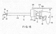
- This modification is an example in which magnets (magnetic bodies) 362 and 364 are arranged at the distal end of the rotation knob 28 and outside the exterior case 32 of the handle unit 22, respectively, and the magnetic forces of the pair of magnets 362 and 364 fix the liquid feeder 16 to the handle unit 22.
- the first magnet 362 is arranged as a fixing section (fixing tool) at the proximal end of the adapter 222.
- the adapter 222 and the first magnet 362 are preferably integrated.
- the second magnet 364 is arranged as a fixing section (fixing tool) in the exterior case 32 of the handle unit 22. The first magnet 362 and the second magnet 364 are arranged to attract each other.
- the magnetic forces of the first magnet 362 and the second magnet 364, which attract each other, can maintain the positional relationship between the adapter 222 and the exterior case 32 of the handle unit 22.
- the first magnet 362 and the second magnet 364 it is possible to perform treatment by combining the surgical treatment instrument 12 and the liquid feeder 16, as described in the first embodiment.
- the second embodiment will be described with reference to FIGS. 16 to 18B .
- This embodiment is a modification of the first embodiment.
- the same members or members having the same functions as in the first embodiment including the respective modifications are denoted by the same reference numerals as much as possible and a detailed description thereof will be omitted.
- a liquid feeder (water feeder) 416 shown in FIGS. 16 to 18B includes a main tube 512 which can be arranged on the outer circumference of a sheath unit 26 and extends outside the sheath unit 26, a connection section 514 which is arranged at the proximal end of the main tube 512 and connects the interior of the main tube 512 and the interior of a liquid feed tube 218 (see FIG. 1A ) from a liquid source 20, and a fixing section (fixing tool) 216 which is arranged in the connection section 514 and fixes part of the connection section 514 to a handle unit 22.
- connection section 514 includes a fixing adapter 522 and a rotation adapter 524.
- the outer shape of each of the fixing adapter 522 and the rotation adapter 524 is a circular shape. However, any appropriate shape can be used.
- the fixing adapter 522 includes an annular body 532, a through hole 534 which penetrates along a center axis C of the body 532, and an annular channel 536 concentrically formed with respect to the center axis C of the body 532.
- the body 532 has a distal end face 532a, a proximal end face 532b, and a side face 532c.
- the annular channel 536 is formed from the distal end face 532a of the body 532 toward its proximal end face 532b up to an appropriate depth but does not penetrate the proximal end face 532b.
- a connector 538 communicating with the annular channel 536 is disposed on the side face 532c of the body 532 of the fixing adapter 522.
- the fixing adapter 522 is connected to the fixing section 216 described in the first embodiment. Therefore, if the fixing section 216 is fixed to an exterior case 32 of the handle unit 22, the fixing adapter 522 maintains a state in which it is positioned with respect to the handle unit 22.
- the through hole 534 is formed to have an opening diameter slightly larger than the outside diameter of the sheath unit 26. If the fixing section 216 is fixed to the exterior case 32 of the handle unit 22, the sheath unit 26 and a probe 24 can freely rotate inside the through hole 534 of the fixing adapter 522.
- the rotation adapter 524 can rotate about the center axis C with respect to the fixing adapter 522.
- the rotation adapter 524 includes a body 542, a through hole 544, an annular convex section 546, and a channel 548.
- the body 542 has a distal end face 542a, a proximal end face 542b, and a side face 542c.
- the through hole 544 penetrates along the center axis C of the body 542.
- the annular convex section 546 is formed on the proximal end face 542b of the body 542.
- the channel 548 is formed in parallel to the center axis C of the body 542.
- the through hole 544 is formed to have an opening diameter slightly larger than the outside diameter of the sheath unit 26.
- Seal members 552a and 552b such as O-rings are disposed on the inner circumferential surface of the through hole 544.
- the sheath unit 26 is supported by the seal members 552a and 552b inside the through hole 544 of the rotation adapter 524. Therefore, the rotation adapter 524 rotates along with the rotation of the sheath unit 26 and the probe 24.
- O-rings 554a and 554b are preferably arranged between the distal end face 532a of the body 532 of the fixing adapter 522 and the proximal end face 542b of the body 542 of the rotation adapter 524. Furthermore, O-rings 556a and 556b are preferably arranged between the annular channel 536 and the inner and outer circumferential surfaces of the annular convex section 546.
- the annular convex section 546 can be fitted in the annular channel 536 of the fixing adapter 522.
- the channel 548 penetrates between a proximal end face 546a of the annular convex section 546 and the distal end face 542a of the body 542.
- a connector 558 communicating with the channel 548 is formed on the distal end face of the rotation adapter 524.
- the proximal end of the main tube 512 is connected to the connector 558.
- the distal end of the main tube 512 is opened near the distal end of an outer sheath 76 of the sheath unit 26.
- main tube 512 is drawn in a shape extending along the outer circumferential surface of the sheath unit 26.
- the main tube 512 is also preferably formed to cover the entire outer circumference of the sheath unit 26, that is, like the main tube 212 described in the first embodiment.
- pinch bodies 564 elastically deformable in a C shape are arranged at appropriate intervals in the main tube 512.
- the pinch bodies 564 are elastically deformed to hold the outer circumferential surface of the sheath unit 26.
- a movable handle 94 is moved closer to a stationary handle 92 to close a jaw 64 with respect to a treatment section 54 of the probe 24.
- the liquid feeder 416 is attached to the surgical treatment instrument 12. More specifically, the treatment section 54 and the jaw 64 are relatively moved from the proximal end side of the connection section 514 to the distal end side.
- the proximal end of the fixing adapter 522 of the connection section 514 abuts against the distal end of a rotation knob 28. At this time, the seal members 552a and 552b inside the rotation adapter 524 of the connection section 514 are in tight contact with the outer circumferential surface of the outer sheath 76.
- the movable handle 94 is released. Accordingly, the movable handle 94 is separated from the stationary handle 92 by the biasing force of the elastic member 144, and the jaw 64 opens with respect to the treatment section 54 of the probe 24.
- An arm 234 of the liquid feeder 416 is moved closer to the exterior case 32 of the handle unit 22.
- the holding section 236 of the liquid feeder 416 is elastically deformed to clamp and hold the exterior of the exterior case 32 of the handle unit 22 by the holding section 236 (see FIG. 16 ).
- the distal end (one end) of the liquid feed tube 218 is fixed to the connector 538 of the connection section 514 of the liquid feeder 416.
- the circumferential-direction position of the connector 558 of the rotation adapter 524 of the liquid feeder 416 with respect to the sheath unit 26 is set to an appropriate position.
- the proximal end of the main tube 512 is attached to the connector 558.
- the pinch bodies 564 clamp the outer circumference of the outer sheath 76 of the sheath unit 26. Therefore, the opening at the distal end of the main tube 512 is arranged at a position near the distal end of the outer sheath 76 of the sheath unit 26.
- the surgical operation system 10 in the state in which the liquid feeder 416 is attached to the surgical treatment instrument 12 is appropriately used to treat a treatment target tissue.
- the sheath unit 26 including the jaw 64 and the probe 24 inside the sheath unit 26 are accordingly pivoted about the center axis C.
- the rotation adapter 524 since the rotation adapter 524 is in tight contact with the seal members 552a and 552b, the rotation adapter 524 and the main tube 512 rotate along with the rotation of the outer sheath 76.
- the positions of the fixing section 216 and the fixing adapter 522 of the liquid feeder 416 with respect to the handle unit 22 are maintained. Therefore, the position of the liquid feed tube 218 connected to the liquid feeder 416 remains unchanged with respect to the handle unit 22.
- the rotation knob 28 is operated to rotate the sheath unit 26 and the probe 24, the liquid feed tube 218 maintains its position with respect to the handle unit 22.
- the liquid feed tube 218 is prevented from winding around the handle unit 22, the transducer unit 14, or the sheath unit 26 attached with the main tube 512.
- the surgical operation system 10 when a treatment target tissue is treated by appropriately operating switches 102 and 104, while controlling the liquid source 20 by a controller 18, the surgical operation system 10 according to this embodiment discharges a liquid from the distal end of the main tube 212 through the liquid source 20, the liquid feed tube 218, the connector 538 of the liquid feeder 416, the annular channel 536 in the fixing adapter 522, and the channel 548 and the main tube 512 in the rotation adapter 524.
- the surgical operation system 10 it is possible to always rotate the probe 24 and sheath unit 26 of the surgical treatment instrument 12 and the main tube 512 of the liquid feeder 416 at the same time. Therefore, the user of the surgical operation system 10 need not arrange the surgical treatment instrument 12 and the liquid feeder 416 from different positions toward the treatment target tissue. That is, unlike a case in which a user (main operator) holds the surgical treatment instrument 12 and another user (assistant) holds the liquid feeder 416, a plurality of users need not appropriately move the surgical treatment instrument 12 and the liquid feeder 416 in cooperation with each other so as to maintain a desired positional relationship.
- the liquid feeder 416 can be moved together, and the main tube 512 of the liquid feeder 416 and the probe 24 and sheath unit 26 of the surgical treatment instrument 12 can always maintain the same positional relationship.
- the operator need not separately hold and move the surgical treatment instrument 12 and the liquid feeder 416 so as to maintain the desired positional relationship.
- the treatment section 54 of the surgical treatment instrument 12 and the main tube 512 of the liquid feeder 416 can always be kept in a predetermined positional relationship. Consequently, by appropriately supplying a liquid such as physiological saline to the treatment section 54 through the main tube 512, the tissue between the jaw 64 and the treatment section 54 is prevented from sticking to, for example, the treatment section 54 and/or the jaw 64 as much as possible while suppressing a rise in temperature of the treatment section 54.
- the surgical operation system 10 when performing treatment while supplying a liquid such as physiological saline to the treatment section 54 of the probe 24, even if the orientation of the jaw 64 is adjusted to an appropriate one, it is possible to always maintain the positional relationship between the liquid feeder 416 and the handle unit 22 of the surgical treatment instrument 12 in the same state. It is thus possible to prevent the liquid feed tube 218 connecting the liquid source 20 and the liquid feeder 416 from winding around, for example, the handle unit 22 of the transducer unit 14, the transducer unit 14, or the main tube 512 of the liquid feeder 416 (the handle unit 22 or a member mounted on the handle unit 22). Therefore, it is possible to prevent the liquid feed tube 218 from winding around the surgical treatment instrument 12 and/or the transducer unit 14 during treatment, and maintain, in the predetermined state, the operability of the surgical treatment instrument 12 grasped by the user.
- a liquid such as physiological saline
- 10 ⁇ surgical operation system 12 ⁇ surgical treatment instrument, 14 ⁇ ultrasonic transducer unit, 14a ⁇ transducer case, 14b ⁇ cable, 16 ⁇ liquid feeder, 18 ⁇ controller, 20 ⁇ liquid source, 22 ⁇ handle unit, 24 ⁇ probe, 26 ⁇ sheath unit, 28 ⁇ rotation knob, 32 ⁇ exterior case, 54 ⁇ treatment section, 56 ⁇ positioning section, 62 ⁇ sheath main body, 64 ⁇ jaw, 76 ⁇ outer sheath, 92 ⁇ stationary handle, 94 ⁇ movable handle, 102 ⁇ upper switch, 104 ⁇ lower switch, 212 ⁇ main tube, 214 ⁇ connection section, 216 ⁇ fixing section, 218 ⁇ liquid feed tube, 222 ⁇ annular adapter, 224 ⁇ seal member, 226 ⁇ connector, 228 ⁇ channel, 232 ⁇ hinge section, 234 ⁇ arm, 236 ⁇ holding section, 238 ⁇ guide section.
Landscapes
- Health & Medical Sciences (AREA)
- Surgery (AREA)
- Engineering & Computer Science (AREA)
- Life Sciences & Earth Sciences (AREA)
- Heart & Thoracic Surgery (AREA)
- Veterinary Medicine (AREA)
- Nuclear Medicine, Radiotherapy & Molecular Imaging (AREA)
- Biomedical Technology (AREA)
- Public Health (AREA)
- Medical Informatics (AREA)
- Molecular Biology (AREA)
- Animal Behavior & Ethology (AREA)
- General Health & Medical Sciences (AREA)
- Physics & Mathematics (AREA)
- Plasma & Fusion (AREA)
- Otolaryngology (AREA)
- Dentistry (AREA)
- Mechanical Engineering (AREA)
- Surgical Instruments (AREA)
Abstract
Description
- This invention relates to a liquid feeder mounted on a treatment instrument, and a treatment apparatus including the liquid feeder and the treatment instrument.
- For example,
U.S. Patent Application Publication No. 2006/0265035 discloses a treatment instrument for treating a tissue by an ultrasonic vibration. This treatment instrument can rotate a sheath unit (long member) by the rotation of a knob. Furthermore, this treatment instrument can externally attach/detach, to/from the sheath unit, a liquid feeder capable of supplying a liquid such as physiological saline to a treatment section (the distal end of the sheath unit) through a liquid feed tube. - When rotating the sheath unit of the treatment instrument disclosed in
U.S. Patent Application Publication No. 2006/0265035 about the center axis, the liquid feeder capable of supplying a liquid unwantedly rotates. Therefore, a tube connected to the liquid feeder to supply a liquid may tend to wind about the handle unit, ultrasonic transducer unit, sheath unit, or the like of the treatment instrument. - The present invention has as its object to provide a liquid feeder capable of preventing, when a user appropriately rotates a sheath unit while grasping a handle unit, a tube (liquid feed channel) for supplying a liquid from winding about the handle unit or a member mounted on it, and a treatment apparatus including the liquid feeder.
- According to one aspect of the present invention, a liquid feeder mounted on a treatment instrument, includes: a main tube that is arranged along a long member of the treatment instrument in which a longitudinal axis is defined and that is configured to flow a liquid to an outer circumference of the long member; a connection section that is arranged on a proximal end side of the main tube along the longitudinal axis and that is configured to connect an interior of the main tube and an interior of a liquid feed channel from a liquid source; and a fixing section that is arranged in the connection section and that is configured to fix the connection section to a handle unit arranged at a proximal end of the long member and grasped by a user.
-
-
FIG. 1A is a schematic view showing a surgical operation system according to the first embodiment. -
FIG. 1B is a schematic view showing a state when a surgical treatment instrument and a liquid feeder are viewed from the direction of anarrow 1B inFIG. 1A . -
FIG. 2 is a schematic longitudinal sectional view showing the distal end of a transducer unit, a probe main body, the proximal end of a sheath unit, and the connection section of a handle unit. -
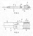
FIG. 3 is a schematic partial sectional view showing the ultrasonic transducer unit of the surgical treatment instrument and a probe connected to the transducer unit according to the first embodiment. -
FIG. 4 is a partial sectional view showing the arrangement of the treatment section of the probe and the jaw of the surgical treatment instrument according to the first embodiment. -
FIG. 5 is a schematic view showing the surgical treatment instrument and liquid feeder of the surgical operation system according to the first embodiment, and showing a state before the liquid feeder is attached to the surgical treatment instrument. -
FIG. 6 is a partial longitudinal sectional view showing the liquid feeder of the surgical operation system according to the first embodiment. -
FIG. 7 is a schematic view showing the surgical treatment instrument and liquid feeder of the surgical operation system according to the first modification of the first embodiment, and showing a state in which the liquid feeder is attached to the surgical treatment instrument. -
FIG. 8 is a schematic view showing the surgical treatment instrument and liquid feeder of the surgical operation system according to the second modification of the first embodiment, and showing a state in which the liquid feeder is attached to the surgical treatment instrument. -
FIG. 9 is a schematic view showing the surgical treatment instrument and liquid feeder of the surgical operation system according to the third modification of the first embodiment, and showing a state in which the liquid feeder is attached to the surgical treatment instrument. -
FIG. 10 is a schematic view showing the surgical treatment instrument and liquid feeder of the surgical operation system according to the fourth modification of the first embodiment, and showing a state in which the liquid feeder is attached to the surgical treatment instrument. -
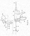
FIG. 11 is a schematic view showing the surgical treatment instrument and liquid feeder of the surgical operation system according to a modification of the fourth modification of the first embodiment, and showing a state in which the liquid feeder is attached to the surgical treatment instrument. -
FIG. 12A is a schematic view showing the surgical treatment instrument and liquid feeder of the surgical operation system according to the fifth modification of the first embodiment, and showing a state in which the liquid feeder is attached to the surgical treatment instrument. -
FIG. 12B is a schematic view showing a state when the surgical treatment instrument and the liquid feeder are viewed from the direction of an arrow 12B inFIG. 12A . -
FIG. 13A is a schematic view showing the surgical treatment instrument and liquid feeder of the surgical operation system according to the sixth modification of the first embodiment, and showing a state in which the liquid feeder is attached to the surgical treatment instrument. -
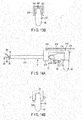
FIG. 13B is a schematic view showing a state when the surgical treatment instrument and the liquid feeder are viewed from the direction of an arrow 13B inFIG. 13A . -
FIG. 14A is a schematic view showing the surgical treatment instrument and liquid feeder of the surgical operation system according to the seventh modification of the first embodiment, and showing a state in which the liquid feeder is attached to the surgical treatment instrument. -
FIG. 14B is a schematic view showing a state when the surgical treatment instrument and liquid feeder are viewed from the direction of an arrow 14B inFIG. 14A . -
FIG. 15 is a schematic view showing the surgical treatment instrument and liquid feeder of the surgical operation system according to the eighth modification of the first embodiment, and showing a state in which the liquid feeder is attached to the surgical treatment instrument. -
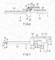
FIG. 16 is a schematic view showing the surgical treatment instrument and liquid feeder of a surgical operation system according to the second embodiment, and showing a state in which the liquid feeder is attached to the surgical treatment instrument. -
FIG. 17 is a schematic view showing the surgical treatment instrument and liquid feeder of the surgical operation system according to the second embodiment, and showing a state before the liquid feeder is attached to the surgical treatment instrument. -
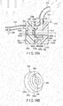
FIG. 18A is a schematic longitudinal sectional view showing the liquid feeder of the surgical operation system according to the first embodiment. -
FIG. 18B is a schematic perspective view showing a rotation adapter shown inFIG. 18A . - Embodiments of the present invention will be described below with reference to the accompanying drawings.
- The first embodiment will be described with reference to
FIGS. 1A to 6 . - As shown in
FIG. 1A , a surgical operation system (treatment apparatus) 10 according to this embodiment includes a surgical treatment instrument (surgical operation device) 12, anultrasonic transducer unit 14, a liquid feeder (water feeder) 16, and acontroller 18. Thesurgical treatment instrument 12 and theliquid feeder 16 are used in combination. Thissurgical operation system 10 further includes aliquid source 20 for supplying a liquid such as physiological saline to theliquid feeder 16. - This embodiment will be explained by assuming that the
surgical treatment instrument 12 is a treatment instrument capable of treating a tissue by an ultrasonic vibration or capable of treating a tissue using high-frequency energy in addition to an ultrasonic vibration. - The
surgical treatment instrument 12 includes ahandle unit 22 for performing various kinds of treatment by operating an end effector (to be described later), a probe (long member) 24, a sheath unit (long member) 26, and arotation knob 28. The handle unit 22 (an exterior case 32 (to be described later)) has a center axis C. For example, thetransducer unit 14, theprobe 24, thesheath unit 26, and therotation knob 28 are connected to thehandle unit 22 on the center axis C. - As shown in
FIGS. 1B and2 , thehandle unit 22 for thesurgical treatment instrument 12 includes the cylindrically formed exterior case (handle main body) 32. Theexterior case 32 is preferably made of a hard plastic material having an electrical insulating property and heat resistance. As shown inFIG. 2 , theprobe 24 and thetransducer unit 14 disposed on the proximal end side of theprobe 24 are supported in theexterior case 32. - As shown in
FIG. 3 , thetransducer unit 14 includes anultrasonic transducer 42 for generating an ultrasonic vibration by being appropriately supplied with power from the controller 18 (seeFIG. 1A ), and a cone-shapedhorn 44 for enlarging the amplitude of the ultrasonic vibration generated by theultrasonic transducer 42. Theultrasonic transducer 42 and thehorn 44 are arranged inside acylindrical transducer case 14a having an electrical insulating property shown inFIG. 1A . Thehorn 44 is attached to anexternal thread 24a at the proximal end of theprobe 24 by a connection thread (internal thread) 46. Thehorn 44 includes anouter flange 44a projecting radially outward with respect to the center axis C of thehorn 44. Theouter flange 44a is supported by thetransducer case 14a. - This embodiment assumes that the
ultrasonic transducer unit 14 is detachably supported by theexterior case 32. However, it is also preferable that theultrasonic transducer unit 14 is fixed to theexterior case 32. - A
cable 14b is connected to the proximal end side of thetransducer case 14a. Thecable 14b can transmit/receive a signal to/from thecontroller 18 shown inFIG. 1A by aswitch 102 or 104 (to be described later) or the like, appropriately supply power to theultrasonic transducer 42 based on the signal input to thecontroller 18, and appropriately supply power to theprobe 24 and a jaw 64 (to be described later) based on the signal input to thecontroller 18. Furthermore, thecontroller 18 can control an adjustment section (not shown) such as a valve for adjusting the flow rate per unit time of physiological saline which flows from theliquid source 20 to theliquid feeder 16. A fluid may be supplied from theliquid source 20 to theliquid feeder 16 by a pump (not shown), or a fluid may be supplied by gravity by arranging theliquid source 20 at a position higher than that of theliquid feeder 16. - The
probe 24 shown inFIG. 3 is designed so that the total length (the length along the center axis C) is an integer multiple of the half-wave length of the ultrasonic vibration. Theprobe 24 includes a rod-shaped probemain body 52 made of metal such as a titanium alloy, and atreatment section 54 provided on the distal end side of the probemain body 52. The ultrasonic vibration generated by theultrasonic transducer 42 is enlarged in amplitude by thehorn 44, and transferred to thetreatment section 54 via the probemain body 52. - A
positioning section 56 which is prevented from rotating with respect to an inner sheath 72 (to be described later) is formed on the outer circumferential surface of the probemain body 52. Thepositioning section 56 is formed into a shape other than a circle. Thepositioning section 56 is preferably arranged in the axial direction at the node position of the vibration. Note that the movement of thepositioning section 56 to the distal end side along the center axis C with respect to theinner sheath 72 is restricted. - As shown in
FIG. 4 , thesheath unit 26 includes a cylindrical sheathmain body 62, and thejaw 64 serving as an end effector disposed on the distal end side of the sheathmain body 62. The sheathmain body 62 includes the cylindricalinner sheath 72 serving as an inner cylinder, a cylindrical driving pipe (driving member) 74, and a cylindricalouter sheath 76 serving as an outer cylinder. The drivingpipe 74 is disposed to be slidable in the axial direction of the center axis C outside theinner sheath 72. Theprobe 24 is inserted into theinner sheath 72. That is, theprobe 24 can transfer the ultrasonic vibration, and the outer circumference of theprobe 24 is covered with thesheath unit 26. - Note that the
inner sheath 72 and theouter sheath 76 are made of a material having an electrical insulating property and heat resistance, such as a PTFE material. In this embodiment, the drivingpipe 74 is made of a conductive material. - The proximal end of the
jaw 64 is pivotably supported by afulcrum pin 82 at the distal end of theinner sheath 72. When assembling theprobe 24 and thesheath unit 26, thejaw 64 is arranged at a position facing thetreatment section 54 of theprobe 24. Thejaw 64 can come into contact with and move away from thetreatment section 54 at the distal end of theprobe 24. - Note that a
fitting section 72a in which thepositioning section 56 of theprobe 24 is fitted is formed on the inner circumferential surface of theinner sheath 72. Thefitting section 72a restricts the movement of theprobe 24 to the distal end side along the center axis C with respect to theinner sheath 72. - The
jaw 64 includes connecting pin supports 84 on the two sides of its proximal end section near thefulcrum pin 82. A connectingpin 86 for connecting thejaw 64 and the drivingpipe 74 is mounted on each connectingpin support 84. When the drivingpipe 74 performs back-and-forth movement in the axial direction, the driving force of the drivingpipe 74 is transferred to thejaw 64 via the connecting pins 86. Thus, thejaw 64 is pivoted about thefulcrum pin 82. Then, thejaw 64 moves closer to and away from thetreatment section 54. That is, thejaw 64 is opened/closed. At this time, if the drivingpipe 74 is moved to the proximal end side, thejaw 64 moves away from thetreatment section 54, that is, moves in an opening direction. If the drivingpipe 74 moves to the distal end side, thejaw 64 moves closer to thetreatment section 54, that is, moves in a closing direction. - Note that the connecting
pins 86 are made of a conductive material. Part of thejaw 64 is made of a conductive material. Therefore, the drivingpipe 74 and thejaw 64 are electrically connected. - As shown in
FIG. 1A , thehandle unit 22 includes a stationary handle (fixing member) 92, and a movable handle (moving member) 94 movable with respect to thestationary handle 92. Therotation knob 28 capable of rotating theprobe 24 and thesheath unit 26 about the center axis C is disposed at the distal end of thehandle unit 22. - As shown in
FIG. 2 , thestationary handle 92 is formed integrally with the exterior case (handle main body) 32, or fixed to theexterior case 32. A plurality of switches (theupper switch 102 and the lower switch 104) are arranged on the distal end face (front face) of theexterior case 32. -
FIG. 2 shows the distal end of thetransducer unit 14, the probemain body 52, the proximal end of thesheath unit 26, and the connection section of thehandle unit 22. As shown inFIG. 2 , in this embodiment, therotation knob 28 is attached to thesheath unit 26. The connection structure of therotation knob 28, theinner sheath 72, the drivingpipe 74, and theouter sheath 76 will be briefly explained. - The
rotation knob 28 includes, on its inner circumferential surface, a pair of engagingpawls 112 projecting inward. Theinner sheath 72 and theouter sheath 76 respectively include a pair of engagingholes 114 and a pair of engagingholes 116 which communicate the interior and the exterior and with which the engagingpawls 112 are engaged. The drivingpipe 74 includes a pair of slidingholes 118 which communicate the interior and the exterior and can relatively move the engagingpawls 112. Each slidinghole 118 is formed as a long hole in a direction along the center axis C. When the engagingpawls 112 of therotation knob 28 are engaged with the engagingholes 114 of theinner sheath 72, the slidingholes 118 of the drivingpipe 74, and the engagingholes 116 of theouter sheath 76, theinner sheath 72, the drivingpipe 74, and theouter sheath 76 are attached to therotation knob 28. - The
inner sheath 72 and theouter sheath 76 are positioned with respect to therotation knob 28. The slidingholes 118 of the drivingpipe 74 allow the drivingpipe 74 to move along the axial direction of the center axis C within a predetermined range with respect to therotation knob 28. On the other hand, the engagingholes holes 118 cause theinner sheath 72, the drivingpipe 74, and theouter sheath 76 to rotate together based on the rotation of therotation knob 28. That is, therotation knob 28 arranged between the proximal end of the sheath unit (long member) 26 and the distal end of thehandle unit 22 rotates thesheath unit 26 about the center axis (longitudinal axis) C. When pivoting therotation knob 28 about the center axis C of thesheath unit 26, the probemain body 52 which is prevented from rotating with respect to theinner sheath 72 inside theexterior case 32 integrally rotates about the center axis C together with therotation knob 28. In synchronism with this operation, thejaw 64 of thesheath unit 26 and thetreatment section 54 of theprobe 24 also rotate about the center axis C integrally with theinner sheath 72, the drivingpipe 74, theouter sheath 76, and the probemain body 52. - That is, it is possible to appropriately adjust the orientations of the
jaw 64 and thetreatment section 54 of theprobe 24 with respect to a treatment target tissue by rotating therotation knob 28 about the center axis C of thesheath unit 26. - Note that an O-
ring 96a is disposed between the inner circumferential surface of therotation knob 28 and the outer circumferential surface of theouter sheath 76 and an O-ring 96b is disposed between the proximal end of therotation knob 28 and the distal end of theexterior case 32 of thehandle unit 22. Therefore, the O-rings exterior case 32 of thehandle unit 22 from the outer circumferential surface of thesheath unit 26. - As shown in
FIG. 1A , theexterior case 32 includes, on the distal end side of thestationary handle 92, anopening 122 which defines the movable range of themovable handle 94. Themovable handle 94 has one end inside theexterior case 32 and the other end outside theexterior case 32. Theopening 122 defines a pivot range within which themovable handle 94 is made to come into contact with and move away from thestationary handle 92. - The
movable handle 94 is arranged at a position far from thestationary handle 92 in theopening 122 while it is not held by the user. - As shown in
FIG. 2 , the proximal end of the drivingpipe 74 projects to the proximal end side of theouter sheath 76 along the center axis C. The proximal end of theinner sheath 72 projects to the proximal end side of the drivingpipe 74 along the center axis C. - A pair of
outer flanges pipe 74. Aslider 142 movable in the axial direction within a predetermined range is disposed between theouter flanges elastic member 144 formed by, for example, a coil spring is disposed between theslider 142 and theouter flange 74a on the distal end side. Consequently, theslider 142 abuts against theouter flange 74b on the proximal end side by theelastic member 144, and is separated from theouter flange 74a on the distal end side. One end of themovable handle 94 is disposed in theslider 142. At this time, themovable handle 94 is separated from thestationary handle 92. - If, for example, a closing operation is performed to move the
movable handle 94 closer to thestationary handle 92, the drivingpipe 74 moves to the distal end side along the center axis C by the biasing force of theelastic member 144 along with the movement of theslider 142 to the distal end side along the center axis C. Consequently, thejaw 64 is closed with respect to thetreatment section 54 of theprobe 24 in synchronism with the movement of the drivingpipe 74. On the other hand, for example, if an opening operation is performed to separate themovable handle 94 from thestationary handle 92, the drivingpipe 74 moves to the proximal end side along the center axis C by the biasing force of theelastic member 144 along with the movement of theslider 142 to the proximal end side along the center axis C. Consequently, thejaw 64 opens with respect to thetreatment section 54 of theprobe 24 in synchronism with the movement of the drivingpipe 74. - A conducting
path 152 through which a current flows when performing high-frequency treatment is formed in thetransducer case 14a. A terminal 154 electrically connected to the conductingpath 152 of thetransducer case 14a of thetransducer unit 14 is disposed on the outer circumferential surface of theinner sheath 72. The terminal 154 has a spring property to continuously contact the conductingpath 152 while maintaining an electrically connected state with respect to the drivingpipe 74 moving along the center axis C. The distal end of the drivingpipe 74 is electrically connected to thejaw 64. Thejaw 64 is used as one electrode of a bipolar electrode. - On the other hand, the
treatment section 54 of theprobe 24 is used as the other electrode of the bipolar electrode. A current flows to thehorn 44 at the proximal end of theprobe 24 through a lead wire (not shown) laid in thetransducer case 14a. - As shown in
FIGS. 5 and6 , theliquid feeder 16 includes amain tube 212 which can be arranged along thesheath unit 26 on its outer circumference and can flow a liquid outside thesheath unit 26, aconnection section 214 which is arranged on the proximal end side of themain tube 212 along the center axis C and connects the interior of themain tube 212 and the interior of a liquid feed tube 218 (seeFIG. 1A ) from theliquid source 20, and a fixing section (fixing tool) 216 which is arranged in theconnection section 214 and fixes theconnection section 214 to thehandle unit 22. Theliquid feed tube 218 is made of a flexible material. Themain tube 212 may be made of a flexible material, similarly to theliquid feed tube 218, or made of a hard material such as a metal material or a hard plastic material. - As shown in
FIG. 6 , theconnection section 214 includes anannular adapter 222 which is arranged outside thesheath unit 26, and aseal member 224 such as an O-ring which is arranged inside theannular adapter 222 and seals a portion with the outer circumferential surface of thesheath unit 26. Note that theseal member 224 can be elastically deformed, and is in tight contact with the outer circumferential surface of thesheath unit 26 to be slidable. Theconnection section 214 includes aconnector 226 for connecting the liquid feed tube (liquid feed channel) 218 to theannular adapter 222. Theannular adapter 222 includes achannel 228 for communicating themain tube 212 and theconnector 226. - The fixing
section 216 includes ahinge section 232 which is pivotable with respect to theconnection section 214. As shown inFIG. 1A , thehinge section 232 allows the fixingsection 216 to pivot between a solid-line position and a broken-line position. - As shown in
FIG. 6 , the fixingsection 216 includes apivotable arm 234 pivoted by thehinge section 232 on theannular adapter 222 of theconnection section 214, and aholding section 236 held by theexterior case 32 of thehandle unit 22. As shown inFIG. 1B , the cross section of the holdingsection 236 has an almost C shape, and is formed to be slightly smaller than the outside diameter of theexterior case 32 of thehandle unit 22. That is, the holdingsection 236 of the fixingsection 216 is used as a clamping section capable of clamping thehandle unit 22. - As shown in
FIG. 6 , thehinge section 232 is formed at a position which does not influence thechannel 228 of theannular adapter 222. - A
guide section 238 for guiding theliquid feed tube 218 is provided between the proximal end of thearm 234 and theholding section 236. Theguide section 238 is formed into a cylindrical shape. - Note that one end (proximal end) of the
liquid feed tube 218 is connected to theconnector 226 via theguide section 238, and other end (distal end) of theliquid feed tube 218 is connected to theliquid source 20. - The action of the
surgical operation system 10 according to this embodiment will be described next. - A case in which the
liquid feeder 16 shown inFIG. 5 is mounted on thesurgical treatment instrument 12 in the state shown inFIG. 5 will be described first. More specifically, theliquid feeder 16 is mounted on thesurgical treatment instrument 12 including
the long member in which the center axis (longitudinal axis) C is defined, that is, theprobe 24 and/or thesheath unit 26, and thehandle unit 22 arranged at the proximal end of thesheath unit 26 and grasped by the user. - The
movable handle 94 is separated from thestationary handle 92. At this time, thejaw 64 arranged at the distal end of thesheath unit 26 is separated from thetreatment section 54 at the distal end of theprobe 24. - If the
movable handle 94 is moved closer to thestationary handle 92, thejaw 64 is moved closer to thetreatment section 54 of theprobe 24 and is closed. In this state, theliquid feeder 16 is attached to thesurgical treatment instrument 12. More specifically, thetreatment section 54 and thejaw 64 are relatively moved from the proximal end side of theadapter 222 to the distal end side. At this time, thetreatment section 54 and thejaw 64 are moved through the interior of themain tube 212. The proximal end of theannular adapter 222 then abuts against the distal end of therotation knob 28. That is, theconnection section 214 is arranged at a position closer to the distal end of themain tube 212 than therotation knob 28. At this time, thejaw 64 and thetreatment section 54 of theprobe 24 project to the distal end side along the center axis C with respect to the distal end of themain tube 212 of theliquid feeder 16. In this example, the distal end of thesheath unit 26 projects to the distal end side, as compared with the distal end of themain tube 212. Furthermore, the fixingsection 216 of theliquid feeder 16 is at the broken-line position inFIG. 1A . - The
movable handle 94 is released. Then, themovable handle 94 is separated from thestationary handle 92 by the biasing force of theelastic member 144, and thejaw 64 opens with respect to thetreatment section 54 of theprobe 24. - The
arm 234 of theliquid feeder 16 is moved closer to theexterior case 32 of thehandle unit 22. Then, the holdingsection 236 of theliquid feeder 16 is elastically deformed to clamp and hold the exterior of theexterior case 32 of thehandle unit 22 by the holding section 236 (seeFIG. 1B ). - The distal end (one end) of the
liquid feed tube 218 is fixed to theconnector 226 via theguide section 238 of the fixingsection 216. - As described above, the
surgical operation system 10 in the state in which theliquid feeder 16 is attached to thesurgical treatment instrument 12 is appropriately used to treat a treatment target tissue. - When the
rotation knob 28 is rotated about the center axis C, thesheath unit 26 including thejaw 64 and theprobe 24 inside thesheath unit 26 are accordingly pivoted about the center axis C with respect to themain tube 212. At this time, the positions of themain tube 212,annular adapter 222, and fixingsection 216 of theliquid feeder 16 with respect to thehandle unit 22 are maintained. Thus, the position of theliquid feed tube 218 connected to theliquid feeder 16 remains unchanged with respect to thehandle unit 22. Therefore, even if therotation knob 28 is operated to rotate thesheath unit 26 and theprobe 24, theliquid feed tube 218 maintains its position with respect to thehandle unit 22. Consequently, theliquid feed tube 218 is prevented from winding about thehandle unit 22, thetransducer unit 14, themain tube 212 of theliquid feeder 16, or the like. Even if theknob 28 of thesurgical treatment instrument 12 is rotated to appropriately rotate thesheath unit 26, the operability of thesurgical treatment instrument 12 is prevented from being lowered. - If, for example, the
upper switch 102 is pressed while the tissue is arranged (grasped) between thejaw 64 and thetreatment section 54 of theprobe 24, the tissue is coagulated and incised by Joule heat generated by high-frequency energy and the ultrasonic vibration. If, for example, thelower switch 104 is pressed while the tissue is arranged between thejaw 64 and thetreatment section 54 of theprobe 24, the tissue is heated and coagulated (if the tissue is a blood vessel, it is sealed) by Joule heat generated by high-frequency energy. - That is, by selectively pressing the
upper switch 102 and thelower switch 104, a treatment function (for example, coagulation, incision, or the like) in thetreatment section 54 of theprobe 24 is selected. - When the
upper switch 102 and thelower switch 104 are selectively pressed to treat the tissue, thecontroller 18 is controlled to supply a liquid such as physiological saline from theliquid source 20 to theliquid feeder 16 through theliquid feed tube 218. Then, the liquid is discharged from the distal end of themain tube 212 through theliquid source 20, theliquid feed tube 218, theconnector 226 of theliquid feeder 16, thechannel 228 in theadapter 222, and themain tube 212. At this time, the liquid enters between the tissue and thejaw 64 and between the tissue and thetreatment section 54 of theprobe 24. The liquid serves as a lubricant. Thus, the tissue is prevented from sticking to thejaw 64 and/or thetreatment section 54 of theprobe 24. - If treatment is performed to incise the tissue without supplying any liquid, the treated tissue tends to stick to the
treatment section 54 of theprobe 24. To the contrary, if treatment is performed while supplying a liquid, the liquid serves as a lubricant, and the tissue is difficult to stick to thetreatment section 54, as compared with a case in which treatment is performed without supplying any liquid. Therefore, if treatment is performed while supplying a liquid, it is readily recognized that the treatment target tissue has been separated by incision. - When the tissue is treated by the ultrasonic vibration by pressing the
upper switch 102, the temperature of thetreatment section 54 of theprobe 24 becomes high due to frictional heat with the tissue. By making the liquid contact thetreatment section 54 of theprobe 24, a rise in temperature of thetreatment section 54 of theprobe 24 is suppressed, as compared with a case in which no liquid is supplied. - In the
surgical operation system 10 according to this embodiment, theprobe 24 andsheath unit 26 of thesurgical treatment instrument 12 and themain tube 212 of theliquid feeder 16 can be concentrically arranged. More specifically, themain tube 212 of theliquid feeder 16 can be arranged outside thesheath unit 26 of thesurgical treatment instrument 12. Therefore, the user of thesurgical operation system 10 need not arrange thesurgical treatment instrument 12 and theliquid feeder 16 from different positions toward the treatment target tissue. That is, unlike a case in which a user (main operator) holds thesurgical treatment instrument 12 and another user (assistant) holds theliquid feeder 16, a plurality of users need not appropriately move thesurgical treatment instrument 12 and theliquid feeder 16 in cooperation with each other so as to maintain a desired positional relationship. If the user moves thesurgical treatment instrument 12, theliquid feeder 16 can be moved together, thereby always maintaining the concentric positional relationship between themain tube 212 of theliquid feeder 16 and theprobe 24 andsheath unit 26 of thesurgical treatment instrument 12. Thus, the operator need not separately hold and move thesurgical treatment instrument 12 and theliquid feeder 16 so as to maintain the desired positional relationship. - Therefore, in the
surgical operation system 10 according to this embodiment, thetreatment section 54 of thesurgical treatment instrument 12 and themain tube 212 of theliquid feeder 16 can always be kept in a predetermined positional relationship. Consequently, by appropriately supplying a liquid such as physiological saline to thetreatment section 54 through themain tube 212, the tissue between thejaw 64 and thetreatment section 54 is prevented from sticking to, for example, thetreatment section 54 and/or thejaw 64 as much as possible while suppressing a rise in temperature of thetreatment section 54. - As described above, in the
surgical operation system 10 according to this embodiment, when performing treatment while supplying a liquid such as physiological saline to thetreatment section 54 of theprobe 24, even if the orientation of thejaw 64 is adjusted to an appropriate one, it is possible to always maintain the positional relationship between theliquid feeder 16 and thehandle unit 22 of thesurgical treatment instrument 12 in the same state. It is thus possible to prevent theliquid feed tube 218 connecting theliquid source 20 and theliquid feeder 16 from winding around, for example, thehandle unit 22 of thetransducer unit 14, thetransducer unit 14, or themain tube 212 of the liquid feeder 16 (thehandle unit 22 or a member mounted on the handle unit 22). Therefore, it is possible to prevent theliquid feed tube 218 from winding around thesurgical treatment instrument 12 and/or thetransducer unit 14 during treatment, and maintain, in the predetermined state, the operability of thesurgical treatment instrument 12 grasped by the user. - That is, the
liquid feeder 16 mounted on thesurgical treatment instrument 12 including the sheath unit (long member) 26 in which the center axis (longitudinal axis) C is defined and thehandle unit 22 arranged at the proximal end of thesheath unit 26 and grasped by the user according to this embodiment includes themain tube 212 which is arranged on the outer circumference of thesheath unit 26 and can flow a liquid to the outer circumference of thesheath unit 26, theconnection section 214 which is arranged on the proximal end side of themain tube 212 along the center axis C and connects the interior of themain tube 212 and the interior of the liquid feed tube (liquid feed channel) 218 from theliquid source 20, and thefixing section 216 which is arranged in theconnection section 214 and fixes theconnection section 214 to thehandle unit 22. - The surgical operation system (treatment apparatus) 10 includes the
surgical treatment instrument 12 including the sheath unit (long member) 26 in which the center axis (longitudinal axis) C is defined and thehandle unit 22 arranged at the proximal end of thesheath unit 26 and grasped by the user, and the above-describedliquid feeder 16 mounted on thesurgical treatment instrument 12. - Note that an example in which the
movable handle 94 is arranged on the front side with respect to thestationary handle 92 in thesurgical treatment instrument 12 according to this embodiment has been explained. However, themovable handle 94 may be arranged on the rear side with respect to thestationary handle 92, as a matter of course. - Next, the first modification of the first embodiment will be described with reference to
FIG. 7 . - This modification is an example in which the
fixing section 216 of theliquid feeder 16 and the outer circumferential surface of theexterior case 32 of thehandle unit 22 of thesurgical treatment instrument 12 are fixed by an adhesive or the like. - Even if the holding
section 236 of the fixingsection 216 of theliquid feeder 16 is fixed to the outer circumferential surface of theexterior case 32 of thehandle unit 22 of thesurgical treatment instrument 12 in this way, it is possible to perform treatment by combining thesurgical treatment instrument 12 and theliquid feeder 16, as described in the first embodiment. - That is, the first embodiment assumes that the outer circumferential surface of the
exterior case 32 is clamped by the holdingsection 236. As described in this modification, however, it is also preferable to hold a state in which theholding section 236 is in tight contact with the outer circumferential surface of theexterior case 32 by an adhesive or the like. - Next, the second modification of the first embodiment will be described with reference to
FIG. 8 . - This modification is an example in which the
fixing section 216 of theliquid feeder 16 is hooked on the outer circumferential surface of theexterior case 32 of thehandle unit 22 of thesurgical treatment instrument 12. - As shown in
FIG. 8 , a convex section (fixed section) 312 is formed at the proximal end of theexterior case 32. Ahook section 314 which can be hooked on theconvex section 312 is formed in thefixing section 216 of theliquid feeder 16. In this modification, thehook section 314 of the fixingsection 216 is formed into a ring shape. - Even if the
fixing section 216 of theliquid feeder 16 is hooked on the outer circumferential surface of theexterior case 32 of thehandle unit 22 of thesurgical treatment instrument 12 in this way, it is possible to perform treatment by combining thesurgical treatment instrument 12 and theliquid feeder 16, as described in the first embodiment. - Next, the third modification of the first embodiment will be described with reference to
FIG. 9 . - This modification is an example in which the
fixing section 216 of theliquid feeder 16 is hooked on the outer circumferential surface of theexterior case 32 of thehandle unit 22 of thesurgical treatment instrument 12. - As shown in
FIG. 9 , a concave section (fixed section) 322 is formed at the proximal end of theexterior case 32. Ahook section 324 which can be hooked on theconcave section 322 is formed in thefixing section 216 of theliquid feeder 16. In this modification, thehook section 324 of the fixingsection 216 is formed to be fitted in theconcave section 322. - Even if the
fixing section 216 of theliquid feeder 16 is hooked on the outer circumferential surface of theexterior case 32 of thehandle unit 22 of thesurgical treatment instrument 12 in this way, it is possible to perform treatment by combining thesurgical treatment instrument 12 and theliquid feeder 16, as described in the first embodiment. - Next, the fourth modification of the first embodiment will be described with reference to
FIG. 10 . - This modification is an example in which the
fixing section 216 of theliquid feeder 16 is hooked on themovable handle 94 of thehandle unit 22 of thesurgical treatment instrument 12. - As shown in
FIG. 10 , ahook section 332 which can be hooked on the movable handle (fixed section) 94 is formed in thefixing section 216 of theliquid feeder 16. In this modification, thehook section 332 of the fixingsection 216 is formed into a ring shape. - Even if the
fixing section 216 of theliquid feeder 16 is hooked on themovable handle 94 of thehandle unit 22 of thesurgical treatment instrument 12 in this way, it is possible to perform treatment by combining thesurgical treatment instrument 12 and theliquid feeder 16, as described in the first embodiment. - Note that as shown in
FIG. 11 , it is also preferable to hook thehook section 332 of the fixingsection 216 of theliquid feeder 16 on the stationary handle (fixed section) 92 of thehandle unit 22 of thesurgical treatment instrument 12, as a matter of course. - That is, the
hook section 332 of the fixingsection 216 need only be supported by one of thestationary handle 92 and themovable handle 94. - Next, the fifth modification of the first embodiment will be described with reference to
FIGS. 12A and 12B . - This modification is an example in which the distal end and proximal end of the
handle unit 22 are sandwiched by theliquid feeder 16. - As shown in
FIG. 12A , theadapter 222 of theliquid feeder 16 abuts against the distal end of therotation knob 28. The fixingsection 216 of theliquid feeder 16 includes a clampingbody 342 for sandwiching theexterior case 32 of thehandle unit 22 in cooperation with theadapter 222. As shown inFIG. 12B , the clampingbody 342 includes anopening 342a in which thetransducer unit 14 is disposed. - As described above, when the
adapter 222 of theliquid feeder 16 and the clampingbody 342 of the fixingsection 216 clamp the distal end of therotation knob 28 and the proximal end of theexterior case 32 of thehandle unit 22, it is possible to perform treatment by combining thesurgical treatment instrument 12 and theliquid feeder 16, as described in the first embodiment. - Next, the sixth modification of the first embodiment will be described with reference to
FIGS. 13A and13B . - This modification is an example in which the exterior of the
exterior case 32 of thehandle unit 22 is sandwiched by the fixingsection 216 of theliquid feeder 16. - As shown in
FIGS. 13A and13B , one or a plurality ofair bags 352 which press the exterior of theexterior case 32 of thehandle unit 22 when air is inserted and release the pressure of the exterior of theexterior case 32 of thehandle unit 22 when air is removed are arranged inside the holdingsection 236 of the fixingsection 216 of theliquid feeder 16. - Note that tubes (not shown) which are connected to the
air bags 352 to insert/remove air into/from them are preferably tied into a bundle together with theliquid feed tube 218. In this case, the tubes (not shown) and theliquid feed tube 218 are prevented from being tangled. - As described above, when air is inserted into the
air bags 352 to press and clamp the exterior of theexterior case 32 of thehandle unit 22 by the fixingsection 216 of theliquid feeder 16, it is possible to perform treatment by combining thesurgical treatment instrument 12 and theliquid feeder 16, as described in the first embodiment. - Next, the seventh modification of the first embodiment will be described with reference to
FIGS. 14A and 14B . - This modification is an example in which the
fixing section 216 of theliquid feeder 16 is plastically deformed to sandwich the exterior of theexterior case 32 of thehandle unit 22. - A plastically deformable metal material is used for the
holding section 236 of the fixingsection 216 of theliquid feeder 16 shown inFIGS. 14A and 14B . - When the holding
section 236 of theliquid feeder 16 is plastically deformed and thefixing section 216 of theliquid feeder 16 clamps the exterior of theexterior case 32 of thehandle unit 22, that is, when the holdingsection 236 is fixed to the outer circumferential surface of theexterior case 32 by caulking, it is possible to perform treatment by combining thesurgical treatment instrument 12 and theliquid feeder 16, as described in the first embodiment. - Note that when, instead of plastically deforming the holding
section 236, the exterior of theexterior case 32 of thehandle unit 22 is clamped by the fixingsection 216 of theliquid feeder 16 using a material which is deformed by appropriately applying heat, that is, the holdingsection 236 is fixed to the outer circumferential surface of theexterior case 32 by heat deformation, it is also possible to perform treatment by combining thesurgical treatment instrument 12 and theliquid feeder 16, as described in the first embodiment. - Next, the eighth modification of the first embodiment will be described with reference to
FIG. 15 . - This modification is an example in which magnets (magnetic bodies) 362 and 364 are arranged at the distal end of the
rotation knob 28 and outside theexterior case 32 of thehandle unit 22, respectively, and the magnetic forces of the pair ofmagnets liquid feeder 16 to thehandle unit 22. - As shown in
FIG. 15 , thefirst magnet 362 is arranged as a fixing section (fixing tool) at the proximal end of theadapter 222. Theadapter 222 and thefirst magnet 362 are preferably integrated. Thesecond magnet 364 is arranged as a fixing section (fixing tool) in theexterior case 32 of thehandle unit 22. Thefirst magnet 362 and thesecond magnet 364 are arranged to attract each other. - The magnetic forces of the
first magnet 362 and thesecond magnet 364, which attract each other, can maintain the positional relationship between theadapter 222 and theexterior case 32 of thehandle unit 22. Thus, by using thefirst magnet 362 and thesecond magnet 364, it is possible to perform treatment by combining thesurgical treatment instrument 12 and theliquid feeder 16, as described in the first embodiment. - The second embodiment will be described with reference to
FIGS. 16 to 18B . This embodiment is a modification of the first embodiment. The same members or members having the same functions as in the first embodiment including the respective modifications are denoted by the same reference numerals as much as possible and a detailed description thereof will be omitted. - A liquid feeder (water feeder) 416 shown in
FIGS. 16 to 18B includes amain tube 512 which can be arranged on the outer circumference of asheath unit 26 and extends outside thesheath unit 26, aconnection section 514 which is arranged at the proximal end of themain tube 512 and connects the interior of themain tube 512 and the interior of a liquid feed tube 218 (seeFIG. 1A ) from aliquid source 20, and a fixing section (fixing tool) 216 which is arranged in theconnection section 514 and fixes part of theconnection section 514 to ahandle unit 22. - As shown in
FIG. 18A , theconnection section 514 includes a fixingadapter 522 and arotation adapter 524. Assume that the outer shape of each of the fixingadapter 522 and therotation adapter 524 is a circular shape. However, any appropriate shape can be used. - The fixing
adapter 522 includes anannular body 532, a throughhole 534 which penetrates along a center axis C of thebody 532, and anannular channel 536 concentrically formed with respect to the center axis C of thebody 532. Thebody 532 has adistal end face 532a, aproximal end face 532b, and aside face 532c. Theannular channel 536 is formed from thedistal end face 532a of thebody 532 toward its proximal end face 532b up to an appropriate depth but does not penetrate theproximal end face 532b. Aconnector 538 communicating with theannular channel 536 is disposed on theside face 532c of thebody 532 of the fixingadapter 522. - The fixing
adapter 522 is connected to thefixing section 216 described in the first embodiment. Therefore, if thefixing section 216 is fixed to anexterior case 32 of thehandle unit 22, the fixingadapter 522 maintains a state in which it is positioned with respect to thehandle unit 22. - The through
hole 534 is formed to have an opening diameter slightly larger than the outside diameter of thesheath unit 26. If thefixing section 216 is fixed to theexterior case 32 of thehandle unit 22, thesheath unit 26 and aprobe 24 can freely rotate inside the throughhole 534 of the fixingadapter 522. - The
rotation adapter 524 can rotate about the center axis C with respect to the fixingadapter 522. - As shown in
FIG. 18B , therotation adapter 524 includes a body 542, a throughhole 544, an annularconvex section 546, and achannel 548. The body 542 has adistal end face 542a, aproximal end face 542b, and aside face 542c. The throughhole 544 penetrates along the center axis C of the body 542. The annularconvex section 546 is formed on theproximal end face 542b of the body 542. Thechannel 548 is formed in parallel to the center axis C of the body 542. - The through
hole 544 is formed to have an opening diameter slightly larger than the outside diameter of thesheath unit 26.Seal members hole 544. Thesheath unit 26 is supported by theseal members hole 544 of therotation adapter 524. Therefore, therotation adapter 524 rotates along with the rotation of thesheath unit 26 and theprobe 24. - Note that O-
rings distal end face 532a of thebody 532 of the fixingadapter 522 and theproximal end face 542b of the body 542 of therotation adapter 524. Furthermore, O-rings annular channel 536 and the inner and outer circumferential surfaces of the annularconvex section 546. - The annular
convex section 546 can be fitted in theannular channel 536 of the fixingadapter 522. Thechannel 548 penetrates between aproximal end face 546a of the annularconvex section 546 and thedistal end face 542a of the body 542. - As shown in
FIG. 18A , aconnector 558 communicating with thechannel 548 is formed on the distal end face of therotation adapter 524. The proximal end of themain tube 512 is connected to theconnector 558. The distal end of themain tube 512 is opened near the distal end of anouter sheath 76 of thesheath unit 26. - Note that the
main tube 512 is drawn in a shape extending along the outer circumferential surface of thesheath unit 26. However, themain tube 512 is also preferably formed to cover the entire outer circumference of thesheath unit 26, that is, like themain tube 212 described in the first embodiment. - For example, pinch
bodies 564 elastically deformable in a C shape are arranged at appropriate intervals in themain tube 512. Thepinch bodies 564 are elastically deformed to hold the outer circumferential surface of thesheath unit 26. - The action of a
surgical operation system 10 according to this embodiment will be described next. - A case in which the
liquid feeder 416 shown inFIG. 17 is mounted on asurgical treatment instrument 12 shown inFIG. 17 will be described first. - A
movable handle 94 is moved closer to astationary handle 92 to close ajaw 64 with respect to atreatment section 54 of theprobe 24. In this state, theliquid feeder 416 is attached to thesurgical treatment instrument 12. More specifically, thetreatment section 54 and thejaw 64 are relatively moved from the proximal end side of theconnection section 514 to the distal end side. - The proximal end of the fixing
adapter 522 of theconnection section 514 abuts against the distal end of arotation knob 28. At this time, theseal members rotation adapter 524 of theconnection section 514 are in tight contact with the outer circumferential surface of theouter sheath 76. - Then, the
movable handle 94 is released. Accordingly, themovable handle 94 is separated from thestationary handle 92 by the biasing force of theelastic member 144, and thejaw 64 opens with respect to thetreatment section 54 of theprobe 24. - An
arm 234 of theliquid feeder 416 is moved closer to theexterior case 32 of thehandle unit 22. The holdingsection 236 of theliquid feeder 416 is elastically deformed to clamp and hold the exterior of theexterior case 32 of thehandle unit 22 by the holding section 236 (seeFIG. 16 ). - The distal end (one end) of the
liquid feed tube 218 is fixed to theconnector 538 of theconnection section 514 of theliquid feeder 416. - On the other hand, the circumferential-direction position of the
connector 558 of therotation adapter 524 of theliquid feeder 416 with respect to thesheath unit 26 is set to an appropriate position. The proximal end of themain tube 512 is attached to theconnector 558. Thepinch bodies 564 clamp the outer circumference of theouter sheath 76 of thesheath unit 26. Therefore, the opening at the distal end of themain tube 512 is arranged at a position near the distal end of theouter sheath 76 of thesheath unit 26. - As described above, the
surgical operation system 10 in the state in which theliquid feeder 416 is attached to thesurgical treatment instrument 12 is appropriately used to treat a treatment target tissue. - When the
rotation knob 28 is rotated about the center axis C, thesheath unit 26 including thejaw 64 and theprobe 24 inside thesheath unit 26 are accordingly pivoted about the center axis C. At this time, since therotation adapter 524 is in tight contact with theseal members rotation adapter 524 and themain tube 512 rotate along with the rotation of theouter sheath 76. At this time, the positions of the fixingsection 216 and the fixingadapter 522 of theliquid feeder 416 with respect to thehandle unit 22 are maintained. Therefore, the position of theliquid feed tube 218 connected to theliquid feeder 416 remains unchanged with respect to thehandle unit 22. Even if, therefore, therotation knob 28 is operated to rotate thesheath unit 26 and theprobe 24, theliquid feed tube 218 maintains its position with respect to thehandle unit 22. Thus, theliquid feed tube 218 is prevented from winding around thehandle unit 22, thetransducer unit 14, or thesheath unit 26 attached with themain tube 512. - As described in the first embodiment, when a treatment target tissue is treated by appropriately operating
switches liquid source 20 by acontroller 18, thesurgical operation system 10 according to this embodiment discharges a liquid from the distal end of themain tube 212 through theliquid source 20, theliquid feed tube 218, theconnector 538 of theliquid feeder 416, theannular channel 536 in the fixingadapter 522, and thechannel 548 and themain tube 512 in therotation adapter 524. - Thus, by making the liquid contact the
treatment section 54 of theprobe 24, a rise in temperature of thetreatment section 54 of theprobe 24 is suppressed, as compared with a case in which no liquid is supplied. - In the
surgical operation system 10 according to this embodiment, it is possible to always rotate theprobe 24 andsheath unit 26 of thesurgical treatment instrument 12 and themain tube 512 of theliquid feeder 416 at the same time. Therefore, the user of thesurgical operation system 10 need not arrange thesurgical treatment instrument 12 and theliquid feeder 416 from different positions toward the treatment target tissue. That is, unlike a case in which a user (main operator) holds thesurgical treatment instrument 12 and another user (assistant) holds theliquid feeder 416, a plurality of users need not appropriately move thesurgical treatment instrument 12 and theliquid feeder 416 in cooperation with each other so as to maintain a desired positional relationship. If the user moves thesurgical treatment instrument 12, theliquid feeder 416 can be moved together, and themain tube 512 of theliquid feeder 416 and theprobe 24 andsheath unit 26 of thesurgical treatment instrument 12 can always maintain the same positional relationship. Thus, the operator need not separately hold and move thesurgical treatment instrument 12 and theliquid feeder 416 so as to maintain the desired positional relationship. - Therefore, in the
surgical operation system 10 according to this embodiment, thetreatment section 54 of thesurgical treatment instrument 12 and themain tube 512 of theliquid feeder 416 can always be kept in a predetermined positional relationship. Consequently, by appropriately supplying a liquid such as physiological saline to thetreatment section 54 through themain tube 512, the tissue between thejaw 64 and thetreatment section 54 is prevented from sticking to, for example, thetreatment section 54 and/or thejaw 64 as much as possible while suppressing a rise in temperature of thetreatment section 54. - As described above, in the
surgical operation system 10 according to this embodiment, when performing treatment while supplying a liquid such as physiological saline to thetreatment section 54 of theprobe 24, even if the orientation of thejaw 64 is adjusted to an appropriate one, it is possible to always maintain the positional relationship between theliquid feeder 416 and thehandle unit 22 of thesurgical treatment instrument 12 in the same state. It is thus possible to prevent theliquid feed tube 218 connecting theliquid source 20 and theliquid feeder 416 from winding around, for example, thehandle unit 22 of thetransducer unit 14, thetransducer unit 14, or themain tube 512 of the liquid feeder 416 (thehandle unit 22 or a member mounted on the handle unit 22). Therefore, it is possible to prevent theliquid feed tube 218 from winding around thesurgical treatment instrument 12 and/or thetransducer unit 14 during treatment, and maintain, in the predetermined state, the operability of thesurgical treatment instrument 12 grasped by the user. - Note that when fixing the
liquid feeder 416 according to this embodiment to thehandle unit 22 of thesurgical treatment instrument 12, it is possible to fix it, as described in each modification of the first embodiment, as a matter of course. - Although the several embodiments have been specifically described with reference to the drawings, the present invention is not restricted to the foregoing embodiments and includes all embodiments carried out without departing from the gist thereof.
- 10···surgical operation system, 12···surgical treatment instrument, 14···ultrasonic transducer unit, 14a···transducer case, 14b···cable, 16···liquid feeder, 18···controller, 20···liquid source, 22···handle unit, 24···probe, 26···sheath unit, 28··· rotation knob, 32···exterior case, 54···treatment section, 56 ···positioning section, 62···sheath main body, 64···jaw, 76···outer sheath, 92···stationary handle, 94···movable handle, 102···upper switch, 104···lower switch, 212···main tube, 214···connection section, 216···fixing section, 218···liquid feed tube, 222··· annular adapter, 224···seal member, 226···connector, 228··· channel, 232···hinge section, 234···arm, 236···holding section, 238···guide section.
Claims (16)
- A liquid feeder mounted on a treatment instrument, comprising:a main tube that is arranged along a long member of the treatment instrument in which a longitudinal axis is defined and that is configured to flow a liquid to an outer circumference of the long member;a connection section that is arranged on a proximal end side of the main tube along the longitudinal axis and that is configured to connect an interior of the main tube and an interior of a liquid feed channel from a liquid source; anda fixing section that is arranged in the connection section and that is configured to fix the connection section to a handle unit arranged at a proximal end of the long member and grasped by a user.
- The liquid feeder of claim 1, wherein the connection section includes an annular adapter, and a seal member arranged inside the annular adapter and configured to seal a portion with the long member.
- The liquid feeder of claim 2, wherein the connection section includes a connector configured to connect the liquid feed channel to the annular adapter.
- The liquid feeder of claim 1, wherein the connection section includes
a fixing adapter fixed to the handle unit together with the fixing section, and
a rotation adapter arranged in the fixing adapter and configured to rotate along with rotation of the long member. - The liquid feeder of claim 1, wherein a pinch body configured to clamp the outer circumference of the long member is disposed in the main tube.
- The liquid feeder of claim 1, wherein the fixing section includes a hinge section configured to pivot with respect to the connection section.
- The liquid feeder of claim 1, wherein the fixing section includes a hook section configured to be hooked on part of the handle unit.
- The liquid feeder of claim 1, wherein the fixing section includes a clamping section configured to clamp the handle unit.
- The liquid feeder of claim 1, wherein the fixing section is fixed to the handle unit by deformation of the fixing section.
- The liquid feeder of claim 1, wherein the fixing section includes a magnetic body fixed to the handle unit by a magnetic force.
- A treatment apparatus comprising:a treatment instrument including a long member in which a longitudinal axis is defined, and a handle unit arranged at a proximal end of the long member and grasped by a user; anda liquid feeder mounted on the treatment instrument and defined in claim 1.
- The treatment apparatus of claim 11, wherein the long member includes a sheath having a distal end which projects to a distal end side, as compared with a distal end of the main tube.
- The treatment apparatus of claim 11, wherein
the long member includes a sheath unit having a distal end which projects to the distal end side, as compared with a distal end of the main tube, and a probe configured to transfer an ultrasonic vibration and having an outer circumference covered with the sheath unit, and
the treatment apparatus includes, at the distal end of the sheath, a jaw configured to come into contact with and move away from an distal end of the probe. - The treatment apparatus of claim 11, wherein
a knob configured to rotate the long member about the longitudinal axis is arranged between the proximal end of the long member and a distal end of the handle unit, and
the connection section is arranged at a position closer to a distal end of the main tube than the knob. - The treatment apparatus of claim 11, wherein the handle unit includes a fixed section to which the fixing section is fixed.
- The treatment apparatus of claim 11, wherein
the handle unit includes a handle main body, a stationary handle extending from the handle main body, and a movable handle configured to come into contact with and move away from the stationary handle, and
the fixing section is supported by one of the stationary handle and the movable handle.
Applications Claiming Priority (2)
| Application Number | Priority Date | Filing Date | Title |
|---|---|---|---|
| JP2014145308 | 2014-07-15 | ||
| PCT/JP2015/062866 WO2016009702A1 (en) | 2014-07-15 | 2015-04-28 | Liquid delivery device and treatment device |
Publications (2)
| Publication Number | Publication Date |
|---|---|
| EP3170468A1 true EP3170468A1 (en) | 2017-05-24 |
| EP3170468A4 EP3170468A4 (en) | 2018-02-28 |
Family
ID=55078206
Family Applications (1)
| Application Number | Title | Priority Date | Filing Date |
|---|---|---|---|
| EP15822824.7A Withdrawn EP3170468A4 (en) | 2014-07-15 | 2015-04-28 | Liquid delivery device and treatment device |
Country Status (5)
| Country | Link |
|---|---|
| US (1) | US10595931B2 (en) |
| EP (1) | EP3170468A4 (en) |
| JP (1) | JP6081654B2 (en) |
| CN (1) | CN106535799B (en) |
| WO (1) | WO2016009702A1 (en) |
Families Citing this family (8)
| Publication number | Priority date | Publication date | Assignee | Title |
|---|---|---|---|---|
| CN109152587B (en) * | 2016-05-25 | 2021-04-13 | 奥林巴斯株式会社 | Tubes, tube units and suction and delivery units |
| US20200022720A1 (en) * | 2017-12-07 | 2020-01-23 | Beijing Smtp Technology Co., Ltd. | Ultrasonic scalpel bit, ultrasonic vibration propagation assembly and ultrasonic hemostasis and cutting system |
| CN112449584B (en) * | 2018-07-23 | 2024-11-01 | 富士胶片株式会社 | Endoscopic treatment equipment |
| EP3827773B1 (en) | 2018-07-23 | 2024-02-07 | FUJIFILM Corporation | Endoscopic treatment instrument |
| WO2020084674A1 (en) * | 2018-10-22 | 2020-04-30 | オリンパス株式会社 | Treatment device |
| US20200375596A1 (en) * | 2019-05-28 | 2020-12-03 | Ethicon Llc | Nozzle Fluid Ingress Prevention Features for Surgical Stapler |
| CN110731815B (en) * | 2019-10-30 | 2020-10-09 | 杭州市第三人民医院 | Vaporization electric cutting mirror for urinary system |
| CN112617970B (en) * | 2020-12-02 | 2022-03-22 | 苏州贝诺医疗器械有限公司 | Laparoscope fallopian tube recanalization clamp |
Family Cites Families (13)
| Publication number | Priority date | Publication date | Assignee | Title |
|---|---|---|---|---|
| US4425115A (en) * | 1977-12-19 | 1984-01-10 | Wuchinich David G | Ultrasonic resonant vibrator |
| US5085657A (en) * | 1983-03-14 | 1992-02-04 | Ben Simhon Haim | Electrosurgical instrument |
| JP2660069B2 (en) * | 1989-11-07 | 1997-10-08 | オリンパス光学工業株式会社 | Ultrasound therapy equipment |
| US5827323A (en) * | 1993-07-21 | 1998-10-27 | Charles H. Klieman | Surgical instrument for endoscopic and general surgery |
| JP4481922B2 (en) * | 2005-05-13 | 2010-06-16 | オリンパスメディカルシステムズ株式会社 | Medical treatment tool |
| US20070156134A1 (en) * | 2005-12-29 | 2007-07-05 | Boston Scientific Scimed, Inc. | Liquid delivery apparatus for tissue ablation |
| JP2008093019A (en) * | 2006-10-06 | 2008-04-24 | Olympus Medical Systems Corp | Reect scope |
| US8083733B2 (en) * | 2008-04-16 | 2011-12-27 | Icecure Medical Ltd. | Cryosurgical instrument with enhanced heat exchange |
| EP2484301B1 (en) * | 2010-02-12 | 2016-06-15 | Olympus Corporation | Ultrasonic treatment device |
| CN103327920B (en) * | 2011-03-01 | 2015-12-02 | 奥林巴斯株式会社 | ultrasonic probe |
| CN103200888B (en) * | 2011-03-28 | 2015-09-30 | 奥林巴斯医疗株式会社 | Ultrasonic treatment device |
| US9211373B2 (en) * | 2011-09-23 | 2015-12-15 | Medtronic Ps Medical, Inc. | Irrigation system and clip for a surgical instrument |
| JP5198683B1 (en) * | 2012-11-21 | 2013-05-15 | 富士システムズ株式会社 | Drain tube for washing electric knife |
-
2015
- 2015-04-28 CN CN201580038512.XA patent/CN106535799B/en active Active
- 2015-04-28 JP JP2016500012A patent/JP6081654B2/en not_active Expired - Fee Related
- 2015-04-28 WO PCT/JP2015/062866 patent/WO2016009702A1/en not_active Ceased
- 2015-04-28 EP EP15822824.7A patent/EP3170468A4/en not_active Withdrawn
-
2017
- 2017-01-12 US US15/404,797 patent/US10595931B2/en active Active
Also Published As
| Publication number | Publication date |
|---|---|
| WO2016009702A1 (en) | 2016-01-21 |
| JPWO2016009702A1 (en) | 2017-04-27 |
| CN106535799A (en) | 2017-03-22 |
| CN106535799B (en) | 2019-06-18 |
| EP3170468A4 (en) | 2018-02-28 |
| US20170119451A1 (en) | 2017-05-04 |
| US10595931B2 (en) | 2020-03-24 |
| JP6081654B2 (en) | 2017-02-15 |
Similar Documents
| Publication | Publication Date | Title |
|---|---|---|
| US10595931B2 (en) | Liquid feeder and treatment apparatus | |
| EP1943970B1 (en) | Ultrasonic operating apparatus | |
| US8974477B2 (en) | Ultrasonic operating apparatus | |
| JP4758519B2 (en) | Surgical instruments | |
| EP1943969B1 (en) | Ultrasonic operating apparatus | |
| CN101396301B (en) | Surgical operating apparatus | |
| CN104470459B (en) | Medical system and method of operation | |
| JP2000000249A (en) | Ultrasonic treatment implement | |
| CN113729927B (en) | Active surgical instrument, split type surgical device and soft tissue robot | |
| CN100413474C (en) | Surgical Instruments | |
| US11317964B2 (en) | Fluid supply instrument, treatment instrument unit, and treatment system | |
| CN101396302A (en) | Surgical operating apparatus | |
| EP1847231B1 (en) | Soft bipolar forceps | |
| JP7286068B2 (en) | Endoscope Microwave Irradiator | |
| CN107530101B (en) | Medical Equipment and Ultrasound Surgical Devices | |
| JP2020162998A (en) | Microwave irradiation equipment for endoscopes | |
| JP6110098B2 (en) | Forceps device | |
| CN112888386B (en) | Treatment device | |
| JP5653814B2 (en) | Endoscopic high-frequency treatment instrument | |
| JP5653814B6 (en) | Endoscopic high-frequency treatment instrument | |
| WO2019239589A1 (en) | Treatment tool |
Legal Events
| Date | Code | Title | Description |
|---|---|---|---|
| STAA | Information on the status of an ep patent application or granted ep patent |
Free format text: STATUS: THE INTERNATIONAL PUBLICATION HAS BEEN MADE |
|
| PUAI | Public reference made under article 153(3) epc to a published international application that has entered the european phase |
Free format text: ORIGINAL CODE: 0009012 |
|
| STAA | Information on the status of an ep patent application or granted ep patent |
Free format text: STATUS: REQUEST FOR EXAMINATION WAS MADE |
|
| 17P | Request for examination filed |
Effective date: 20170126 |
|
| AK | Designated contracting states |
Kind code of ref document: A1 Designated state(s): AL AT BE BG CH CY CZ DE DK EE ES FI FR GB GR HR HU IE IS IT LI LT LU LV MC MK MT NL NO PL PT RO RS SE SI SK SM TR |
|
| AX | Request for extension of the european patent |
Extension state: BA ME |
|
| DAV | Request for validation of the european patent (deleted) | ||
| DAX | Request for extension of the european patent (deleted) | ||
| A4 | Supplementary search report drawn up and despatched |
Effective date: 20180129 |
|
| RIC1 | Information provided on ipc code assigned before grant |
Ipc: A61B 17/29 20060101ALN20180122BHEP Ipc: A61B 18/14 20060101AFI20180122BHEP Ipc: A61B 17/32 20060101ALI20180122BHEP |
|
| GRAP | Despatch of communication of intention to grant a patent |
Free format text: ORIGINAL CODE: EPIDOSNIGR1 |
|
| STAA | Information on the status of an ep patent application or granted ep patent |
Free format text: STATUS: GRANT OF PATENT IS INTENDED |
|
| RIC1 | Information provided on ipc code assigned before grant |
Ipc: A61B 17/32 20060101ALI20190128BHEP Ipc: A61B 18/14 20060101AFI20190128BHEP Ipc: A61B 17/29 20060101ALN20190128BHEP |
|
| INTG | Intention to grant announced |
Effective date: 20190226 |
|
| RIC1 | Information provided on ipc code assigned before grant |
Ipc: A61B 18/14 20060101AFI20190218BHEP Ipc: A61B 17/29 20060101ALN20190218BHEP Ipc: A61B 17/32 20060101ALI20190218BHEP |
|
| STAA | Information on the status of an ep patent application or granted ep patent |
Free format text: STATUS: THE APPLICATION IS DEEMED TO BE WITHDRAWN |
|
| 18D | Application deemed to be withdrawn |
Effective date: 20190709 |