EP3170434A1 - System for connection between shaft and clutch - Google Patents
System for connection between shaft and clutch Download PDFInfo
- Publication number
- EP3170434A1 EP3170434A1 EP16191847.9A EP16191847A EP3170434A1 EP 3170434 A1 EP3170434 A1 EP 3170434A1 EP 16191847 A EP16191847 A EP 16191847A EP 3170434 A1 EP3170434 A1 EP 3170434A1
- Authority
- EP
- European Patent Office
- Prior art keywords
- shaft
- connecting element
- flexible connecting
- clutch
- connection
- Prior art date
- Legal status (The legal status is an assumption and is not a legal conclusion. Google has not performed a legal analysis and makes no representation as to the accuracy of the status listed.)
- Granted
Links
Images
Classifications
-
- A—HUMAN NECESSITIES
- A47—FURNITURE; DOMESTIC ARTICLES OR APPLIANCES; COFFEE MILLS; SPICE MILLS; SUCTION CLEANERS IN GENERAL
- A47J—KITCHEN EQUIPMENT; COFFEE MILLS; SPICE MILLS; APPARATUS FOR MAKING BEVERAGES
- A47J43/00—Implements for preparing or holding food, not provided for in other groups of this subclass
- A47J43/04—Machines for domestic use not covered elsewhere, e.g. for grinding, mixing, stirring, kneading, emulsifying, whipping or beating foodstuffs, e.g. power-driven
- A47J43/07—Parts or details, e.g. mixing tools, whipping tools
- A47J43/0716—Parts or details, e.g. mixing tools, whipping tools for machines with tools driven from the lower side
Definitions
- the present invention relates to the field of mechanical connecting elements, specifically connection between shaft and clutch of a processing vessel in household appliances.
- connection is often problematic for the reasons of sealing as well as loosening of the connection due to high and variable forces exerted upon the clutch during operation of the appliance.
- This solution comprises a nut with thread oriented opposite to the direction of motor rotation and a combination of different washers (see Figure 1 ).
- Said nut is a special metal element integrated in the plastic clutch and enables torque transmission to the metal-shaft via its shape.
- the currently used technique fails to prevent loosening in case of high dynamic loads.
- the purpose of this invention is to develop a concept, which will provide flexible and durable connection between shaft and clutch of the processing vessel in the sense of withstanding high alternative dynamic loads.
- the present invention provides an improved system for connection between shaft and clutch according to claim 1. Further, a household appliance, such as a food processor, according to claim 6 is provided Advantageous embodiments that can be implemented by themselves or in combination are described in dependent claims.
- a system for connection between shaft and clutch of a processing vessel in a motorized household appliance, preferably a food processor, wherein it further comprises a flexible connecting element that provides an irreversible connection between said shaft and clutch during normal operation of the household appliance and wherein the connection is specifically adapted to withstand high dynamic loads arising from operation, e.g. during processing of solid food ingredients is disclosed.
- the connecting element is intended for simple fixing of the shaft and the clutch of the processing vessel to ensure proper positioning and sealing and prevent the failing apart or unwanted dispositioning during operation.
- Conventional solutions involving screwing are not ideal since there are high forces present when solid ingredients are processed. These vibrations can result in unscrewing and loosening of the fixing means.
- the disclosed solution prevents the displacement of the flexible holding element during operation as well as ensures the continuous holding force as a result of the flexibility of the connecting element and the tension forces arising from the geometry of the shaft and optionally other elements.
- a household appliance such as a food processor, adapted for the use of the system for connection between shaft and clutch of a processing vessel is disclosed.
- the objective of the invention is achieved through a flexible connecting element, such as, but not limited to, a washer, provides an irreversible connection between the shaft and the clutch of the processing vessel during normal operation of the household appliance.
- the flexible connecting element is specifically adapted to withstand high dynamic loads arising from operation, e.g. during processing of solid food ingredients.
- the flexible connecting element is additionally positioned onto the shaft through a metal element, preferably fixed onto the clutch which comes into direct contact with the flexible connecting element upon snapping it onto the shaft.
- the meatl element may be inserted into or added to the clutch to increase the tension of the snapped on flexible connecting element. It also increases durability through preventing the wear of plastic parts due to frictional forces arising between the flexible connecting element and the clutch during regular operation of the household appliance.
- the shaft is shaped at its distal end in the region of contact with the clutch in order to allow the flexible connecting element to be snapped on through the central hole in the flexible connecting element, said shaping of the shaft comprising a circumferential indentation with an edge that serves as means of preventing the falling off of the flexible connecting element.
- Conventional solutions involving screwing are not ideal since there are high forces present when solid ingredients are processed. These vibrations can result in unscrewing and loosening of the fixing means.
- the disclosed solution prevents the displacement of the flexible holding element during operation as well as ensures the continuous holding force as a result of the flexibility of the connecting element and the tension forces arising from the geometry of the shaft and optionally other elements.
- said indentation is positioned in regard to the flexible connecting element in such a manner that the distance between the said edge and the metal element is smaller than the axial dimension of the flexible connecting element, resulting in a strain exerted upon the flexible connecting element when it is snapped onto the shaft and further resulting in the increased fixing force.
- the smaller axial distance between the metal element on or by the clutch and the edge of the indentation of the shaft results in the deformation of the flexible connecting element and thus in forces that fix the shaft to the clutch firmly.
- the flexible nature of the connecting element enables for variants and adjustments in the regard to the intended use for the household appliance.
- the flexible connecting element is made of a flexible metallic alloy that is not easily plastically deformed. It is not desirable that the flexible fixing element is plastically deformed, during regular operation of the appliance or during its removal from the shat during maintenance, repairs or cleaning. Therefore a metal alloy with high elasticity and high resistance to plastic deformation must be used.
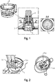
- a processing bowl of the food processor 1 presented in a preferred embodiment comprises as vital elements enabling its function a shaft 2 and a clutch 3. Both said elements are integrated within the food processing vessel 4 as outlined in Figure 1 . They are connected firmly to provide for torque transmission from the motor (not shown) to the blade 5 or another tool within the processing vessel 4.
- Figure 2 explains high dynamic loads arise.
- solid ingredients e.g. slicing of salami with a cutting disc (not shown), in the processing bowl 4
- very high dynamic loads arise which results in very unfavorable conditions for the connection stability between the shaft 2 and the clutch 3.
- Such high dynamic forces may arise when the blade of the cutting disc hits solid ingredients and large force appears in counter-direction of the rotation of the motor. That creates a shock load L S1 ( Figure 2 , left). Due to inertia of the cutting disc this load is released after the slice of solid foodstuff is cut off and another shock load L S2 arises in the direction of motor rotation ( Figure 2 , right).
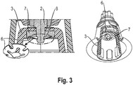
- Our invention solves these drawbacks through compensation and absorption of shocks loads and axial forces through the introduction of a flexible connecting element 6 connecting the shaft 2 and the clutch 3 of the processing vessel 4.
- connection system includes a special-shaped elastic washer as said flexible connecting element 6 and the corresponding mounting shape on the shaft 2.
- Axial movement of the flexible connecting element 6 and consequently of the clutch 3, which is firmly connected to the shaft 2 through the flexible connecting element 6, is prevented by the corresponding slot resulting from the shape of the shaft 2.
- the shape of the shaft 2 allows for irreversible connection of the inner circumference of the flexible connecting element 6 after it has been snapped on.
- the shaft 2 is formed in such a way, that it comprises a circumferential indentation 8 on its section where the clutch 3 is connected. Said indentation 8 is formed so as to prevent the flexible connecting part 6 to slip off the shaft 2 after it has been snapped on.
- the irreversible connection should be understood in a sense that it is irreversible during normal operation of the food processor 1.
- the flexible connecting element 6 can be removed by applying specific and high enough force for replacement, reparation and cleaning purposes. It is conceivable that such removal can be done without plastically deforming the flexible connection element 6, thus allowing its reuse after the desired operation has been completed.
- the flexible connection element 6 When mounted onto the shaft 2 and the corresponding metal element 7 for better fixation, the flexible connection element 6 is pre-stressed with axial force. Special construction of the flexible connecting element 6 and proper selection of its material enable optimal locking properties for mounting; elastic properties for compensating the manufacturing tolerance range of elements present in connection; elastic properties for compensating and absorbing alternating shocks loads; elastic properties for compensating movements caused by axial forces during processing.
- the described system for connection between the shaft 2 and the clutch 3 of the processing vessel 3 provides for the compensation and absorption of high dynamic loads with its elastic properties, but without plastic deformation.
- the latter is very important in the sense of durability of the element. It should be noted, that this solution is very cost-effective as it can actually reduce costs compared to the present state of the art solutions.
- the installation of the flexible connecting element 6 is very simple, preferably as a snap-on.
Landscapes
- Engineering & Computer Science (AREA)
- Mechanical Engineering (AREA)
- Food Science & Technology (AREA)
- Food-Manufacturing Devices (AREA)
Abstract
Description
- The present invention relates to the field of mechanical connecting elements, specifically connection between shaft and clutch of a processing vessel in household appliances.
- A processing vessel for an electrical household appliance, such as a food processor, with the driving axis positioned below the processing bowl in the operating position, requires a secure and efficient connection between the shaft of the blade or another tool positioned within the processing vessel and the clutch element attached to the bottom of the processing vessel. This clutch fits to the clutch on the driving shaft of the motor.
- Said connection is often problematic for the reasons of sealing as well as loosening of the connection due to high and variable forces exerted upon the clutch during operation of the appliance. To prevent the phenomenon of loosening of the connection between shaft and clutch different manufacturers mostly use a similar solution. This solution comprises a nut with thread oriented opposite to the direction of motor rotation and a combination of different washers (see
Figure 1 ). Said nut is a special metal element integrated in the plastic clutch and enables torque transmission to the metal-shaft via its shape. However, the currently used technique fails to prevent loosening in case of high dynamic loads. When bidirectional shock momentums and dynamic axial forces, or in other words high alternative dynamic loads, arise during the processing of harder ingredients, such connection does not work anymore since friction forces between elements in such connection are nullified and the clutch can lose its firm connection with the shaft in the processing vessel, resulting in misalignment, unwanted rotation or or even falling off of the clutch altogether. - Therefore there is a need to develop new solution that would prevent the loosening and/or misalignment effect of shaft to clutch connection in the processing bowl and would allow for simple installation and remain within reasonable costs.
- The purpose of this invention is to develop a concept, which will provide flexible and durable connection between shaft and clutch of the processing vessel in the sense of withstanding high alternative dynamic loads.
- In order to achieve the object underlying the invention, the present invention provides an improved system for connection between shaft and clutch according to claim 1. Further, a household appliance, such as a food processor, according to
claim 6 is provided Advantageous embodiments that can be implemented by themselves or in combination are described in dependent claims. - According to the first aspect of an invention, a system for connection between shaft and clutch of a processing vessel in a motorized household appliance, preferably a food processor, wherein it further comprises a flexible connecting element that provides an irreversible connection between said shaft and clutch during normal operation of the household appliance and wherein the connection is specifically adapted to withstand high dynamic loads arising from operation, e.g. during processing of solid food ingredients is disclosed. The connecting element is intended for simple fixing of the shaft and the clutch of the processing vessel to ensure proper positioning and sealing and prevent the failing apart or unwanted dispositioning during operation. Conventional solutions involving screwing are not ideal since there are high forces present when solid ingredients are processed. These vibrations can result in unscrewing and loosening of the fixing means. The disclosed solution prevents the displacement of the flexible holding element during operation as well as ensures the continuous holding force as a result of the flexibility of the connecting element and the tension forces arising from the geometry of the shaft and optionally other elements.
- According to the second aspect of an invention, a household appliance, such as a food processor, adapted for the use of the system for connection between shaft and clutch of a processing vessel is disclosed.
- The objective of the invention is achieved through a flexible connecting element, such as, but not limited to, a washer, provides an irreversible connection between the shaft and the clutch of the processing vessel during normal operation of the household appliance. The flexible connecting element is specifically adapted to withstand high dynamic loads arising from operation, e.g. during processing of solid food ingredients.
- According to a preferred embodiment, the flexible connecting element is additionally positioned onto the shaft through a metal element, preferably fixed onto the clutch which comes into direct contact with the flexible connecting element upon snapping it onto the shaft. The meatl element may be inserted into or added to the clutch to increase the tension of the snapped on flexible connecting element. It also increases durability through preventing the wear of plastic parts due to frictional forces arising between the flexible connecting element and the clutch during regular operation of the household appliance.
- In another preferred embodiment, the shaft is shaped at its distal end in the region of contact with the clutch in order to allow the flexible connecting element to be snapped on through the central hole in the flexible connecting element, said shaping of the shaft comprising a circumferential indentation with an edge that serves as means of preventing the falling off of the flexible connecting element. Conventional solutions involving screwing are not ideal since there are high forces present when solid ingredients are processed. These vibrations can result in unscrewing and loosening of the fixing means. The disclosed solution prevents the displacement of the flexible holding element during operation as well as ensures the continuous holding force as a result of the flexibility of the connecting element and the tension forces arising from the geometry of the shaft and optionally other elements.
- Further, said indentation is positioned in regard to the flexible connecting element in such a manner that the distance between the said edge and the metal element is smaller than the axial dimension of the flexible connecting element, resulting in a strain exerted upon the flexible connecting element when it is snapped onto the shaft and further resulting in the increased fixing force. The smaller axial distance between the metal element on or by the clutch and the edge of the indentation of the shaft results in the deformation of the flexible connecting element and thus in forces that fix the shaft to the clutch firmly. The flexible nature of the connecting element enables for variants and adjustments in the regard to the intended use for the household appliance.
- Additionally, the flexible connecting element is made of a flexible metallic alloy that is not easily plastically deformed. It is not desirable that the flexible fixing element is plastically deformed, during regular operation of the appliance or during its removal from the shat during maintenance, repairs or cleaning. Therefore a metal alloy with high elasticity and high resistance to plastic deformation must be used.
- Advantageous embodiments and developments which can be used individually or in combination with one another are the subject matter of the dependent claims.
-
-
Figure 1 : State of the art solution -
Figure 2 : Loads and forces arising during the processing of solid ingredients -
Figure 3 : Connection between the shaft and the clutch of the processing vessel through the flexible connecting element - A processing bowl of the food processor 1 presented in a preferred embodiment comprises as vital elements enabling its function a
shaft 2 and aclutch 3. Both said elements are integrated within the food processing vessel 4 as outlined inFigure 1 . They are connected firmly to provide for torque transmission from the motor (not shown) to the blade 5 or another tool within the processing vessel 4. -
Figure 2 explains high dynamic loads arise. During the processing of solid ingredients, e.g. slicing of salami with a cutting disc (not shown), in the processing bowl 4, very high dynamic loads arise which results in very unfavorable conditions for the connection stability between theshaft 2 and theclutch 3. Such high dynamic forces may arise when the blade of the cutting disc hits solid ingredients and large force appears in counter-direction of the rotation of the motor. That creates a shock load LS1 (Figure 2 , left). Due to inertia of the cutting disc this load is released after the slice of solid foodstuff is cut off and another shock load LS2 arises in the direction of motor rotation (Figure 2 , right). Besides the two alternating shock loads which arise at every revolution of the disc, the cutting process is also accompanied with arising dynamic axial forces FDA. Altogether, these phenomena have unfavorable influence on the stability of the connection between theshaft 2 and theclutch 3, in the sense of loosening and misalignment of connected parts. Eventually, this can lead to failure of the connection and of the food processor 1. - Our invention solves these drawbacks through compensation and absorption of shocks loads and axial forces through the introduction of a flexible connecting
element 6 connecting theshaft 2 and theclutch 3 of the processing vessel 4. - In
figure 3 , the connection system is presented that includes a special-shaped elastic washer as said flexible connectingelement 6 and the corresponding mounting shape on theshaft 2. Axial movement of the flexible connectingelement 6 and consequently of theclutch 3, which is firmly connected to theshaft 2 through the flexible connectingelement 6, is prevented by the corresponding slot resulting from the shape of theshaft 2. The shape of theshaft 2 allows for irreversible connection of the inner circumference of the flexible connectingelement 6 after it has been snapped on. In the preferred embodiment, theshaft 2 is formed in such a way, that it comprises a circumferential indentation 8 on its section where theclutch 3 is connected. Said indentation 8 is formed so as to prevent the flexible connectingpart 6 to slip off theshaft 2 after it has been snapped on. The irreversible connection should be understood in a sense that it is irreversible during normal operation of the food processor 1. If desired, the flexible connectingelement 6 can be removed by applying specific and high enough force for replacement, reparation and cleaning purposes. It is conceivable that such removal can be done without plastically deforming theflexible connection element 6, thus allowing its reuse after the desired operation has been completed. When mounted onto theshaft 2 and the corresponding metal element 7 for better fixation, theflexible connection element 6 is pre-stressed with axial force. Special construction of the flexible connectingelement 6 and proper selection of its material enable optimal locking properties for mounting; elastic properties for compensating the manufacturing tolerance range of elements present in connection; elastic properties for compensating and absorbing alternating shocks loads; elastic properties for compensating movements caused by axial forces during processing. During the entire processing cycle the described system for connection between theshaft 2 and theclutch 3 of theprocessing vessel 3 provides for the compensation and absorption of high dynamic loads with its elastic properties, but without plastic deformation. The latter is very important in the sense of durability of the element. It should be noted, that this solution is very cost-effective as it can actually reduce costs compared to the present state of the art solutions. The installation of the flexible connectingelement 6 is very simple, preferably as a snap-on. -
- 1
- Food processor
- 2
- Shaft
- 3
- Clutch
- 4
- Processing bowl
- 5
- Blade
- 6
- Flexible connecting element
- 7
- Metal element
- 8
- Indentation
- LS1
- load shock 1
- LS2
-
load shock 2 - FDA
- dynamic axial forces
Claims (6)
- A system for connection between shaft (2) and clutch (3) of a processing vessel (4) in a motorized household appliance, preferably a food processor (1), characterized in that it further comprises a flexible connecting element (6) that provides an irreversible connection between said shaft (2) and clutch (3) during normal operation of the household appliance wherein the connection is specifically adapted to withstand high dynamic loads arising from operation, e.g. during processing of solid food ingredients.
- The system according to claim 1, characterized in that said flexible connecting element (6) is additionally positioned onto the shaft (2) through a metal element (7), preferably fixed onto the clutch (3) which comes into direct contact with the flexible connecting element (6) upon snapping it onto the shaft (2).
- The system according to claim 1 or 2, characterized in that the shaft (2) is shaped at its distal end in the region of contact with the clutch (3) in order to allow the flexible connecting element (6) to be snapped on through the central hole in the flexible connecting element (6), said shaping of the shaft (2) comprising a circumferential indentation (8) with an edge that serves as means of preventing the falling off of the flexible connecting element (6)
- The system according to any of the previous claims, characterized in that said indentation (6) is positioned in regard to the flexible connecting element (6) in such a manner that the distance between the said edge and the metal element (7) is smaller than the axial dimension of the flexible connecting element (6), resulting in a strain exerted upon the flexible connecting element (6) when it is snapped onto the shaft (2) and further resulting in the increased fixing force.
- The system according to any of the previous claims, characterized in that the flexible connecting element (6) is made of a flexible metallic alloy that is not easily plastically deformed.
- A household appliance, such as a food processor (1), adapted for the use of the system according to claim 1.
Priority Applications (1)
| Application Number | Priority Date | Filing Date | Title |
|---|---|---|---|
| SI201630088T SI3170434T1 (en) | 2015-11-20 | 2016-09-30 | System for connection between shaft and clutch |
Applications Claiming Priority (1)
| Application Number | Priority Date | Filing Date | Title |
|---|---|---|---|
| SI201500281A SI25084A (en) | 2015-11-20 | 2015-11-20 | An improved system for the connection between the axle and the clutch |
Publications (2)
| Publication Number | Publication Date |
|---|---|
| EP3170434A1 true EP3170434A1 (en) | 2017-05-24 |
| EP3170434B1 EP3170434B1 (en) | 2018-09-12 |
Family
ID=57208071
Family Applications (1)
| Application Number | Title | Priority Date | Filing Date |
|---|---|---|---|
| EP16191847.9A Active EP3170434B1 (en) | 2015-11-20 | 2016-09-30 | System for connection between shaft and clutch |
Country Status (2)
| Country | Link |
|---|---|
| EP (1) | EP3170434B1 (en) |
| SI (2) | SI25084A (en) |
Citations (2)
| Publication number | Priority date | Publication date | Assignee | Title |
|---|---|---|---|---|
| FR2967340A1 (en) * | 2010-11-16 | 2012-05-18 | Seb Sa | WORKING CONTAINER FOR CULINARY PREPARATION ELECTRICAL APPLIANCES |
| CN203647177U (en) * | 2014-01-21 | 2014-06-18 | 主力实业(深圳)有限公司 | Stirring hook and stirrer |
-
2015
- 2015-11-20 SI SI201500281A patent/SI25084A/en not_active IP Right Cessation
-
2016
- 2016-09-30 SI SI201630088T patent/SI3170434T1/en unknown
- 2016-09-30 EP EP16191847.9A patent/EP3170434B1/en active Active
Patent Citations (2)
| Publication number | Priority date | Publication date | Assignee | Title |
|---|---|---|---|---|
| FR2967340A1 (en) * | 2010-11-16 | 2012-05-18 | Seb Sa | WORKING CONTAINER FOR CULINARY PREPARATION ELECTRICAL APPLIANCES |
| CN203647177U (en) * | 2014-01-21 | 2014-06-18 | 主力实业(深圳)有限公司 | Stirring hook and stirrer |
Also Published As
| Publication number | Publication date |
|---|---|
| SI3170434T1 (en) | 2018-11-30 |
| SI25084A (en) | 2017-05-31 |
| EP3170434B1 (en) | 2018-09-12 |
Similar Documents
| Publication | Publication Date | Title |
|---|---|---|
| CN103104581B (en) | Screw assembly element | |
| US8899894B2 (en) | Device for fasting a component to a fastening stud | |
| EP2526308B1 (en) | System of fastening elements defined by a nut and a drawbar; drawbar and nut | |
| US20160377109A1 (en) | Fastening device | |
| JP2014173728A (en) | Screw connection, in particular, for clamp, and clamp | |
| EP3170434B1 (en) | System for connection between shaft and clutch | |
| CN104500522B (en) | Double-nut locking mechanism | |
| CN108071642B (en) | Fastening member | |
| EP3336372B1 (en) | A mixer comprising a clamping sleeve assembly | |
| JP2015166621A (en) | Bolt fastening structure and bolt fastening method using the same | |
| US10415650B2 (en) | Device for transmitting a torque from an internal combustion engine to an auxiliary unit | |
| US20100135775A1 (en) | Turbomachine, especially steam turbine | |
| JP5465093B2 (en) | Loosening prevention screw | |
| CN106246702B (en) | Deformable body and fastening structure comprising deformable body and creep-resistant ring | |
| JP6512009B2 (en) | Fastening device | |
| US9903428B2 (en) | Connecting means for brake disc assembly | |
| US7828500B2 (en) | Threaded engagement element with self-locking threads | |
| WO2014087309A1 (en) | Fastening device, fastening system, washing machine with fastening system, and method for manufacture of fastening device | |
| KR102019481B1 (en) | Spring strut mount | |
| CN110345174B (en) | Actuating element comprising a torque limiting device | |
| CN111601977B (en) | Device with a rotationally fixed connection | |
| CN203762872U (en) | Pressure cooker | |
| EP2492521B1 (en) | Retaining element for attachment in a hole | |
| JP2009092108A (en) | Structure for fastening rotating body and rotating shaft | |
| KR20110005565U (en) | Lead screw assembly |
Legal Events
| Date | Code | Title | Description |
|---|---|---|---|
| PUAI | Public reference made under article 153(3) epc to a published international application that has entered the european phase |
Free format text: ORIGINAL CODE: 0009012 |
|
| AK | Designated contracting states |
Kind code of ref document: A1 Designated state(s): AL AT BE BG CH CY CZ DE DK EE ES FI FR GB GR HR HU IE IS IT LI LT LU LV MC MK MT NL NO PL PT RO RS SE SI SK SM TR |
|
| AX | Request for extension of the european patent |
Extension state: BA ME |
|
| 17P | Request for examination filed |
Effective date: 20171124 |
|
| RBV | Designated contracting states (corrected) |
Designated state(s): AL AT BE BG CH CY CZ DE DK EE ES FI FR GB GR HR HU IE IS IT LI LT LU LV MC MK MT NL NO PL PT RO RS SE SI SK SM TR |
|
| GRAP | Despatch of communication of intention to grant a patent |
Free format text: ORIGINAL CODE: EPIDOSNIGR1 |
|
| RIC1 | Information provided on ipc code assigned before grant |
Ipc: A47J 43/07 20060101AFI20180321BHEP |
|
| INTG | Intention to grant announced |
Effective date: 20180420 |
|
| GRAS | Grant fee paid |
Free format text: ORIGINAL CODE: EPIDOSNIGR3 |
|
| GRAA | (expected) grant |
Free format text: ORIGINAL CODE: 0009210 |
|
| AK | Designated contracting states |
Kind code of ref document: B1 Designated state(s): AL AT BE BG CH CY CZ DE DK EE ES FI FR GB GR HR HU IE IS IT LI LT LU LV MC MK MT NL NO PL PT RO RS SE SI SK SM TR |
|
| REG | Reference to a national code |
Ref country code: GB Ref legal event code: FG4D |
|
| REG | Reference to a national code |
Ref country code: CH Ref legal event code: EP |
|
| REG | Reference to a national code |
Ref country code: IE Ref legal event code: FG4D |
|
| REG | Reference to a national code |
Ref country code: DE Ref legal event code: R096 Ref document number: 602016005524 Country of ref document: DE |
|
| REG | Reference to a national code |
Ref country code: AT Ref legal event code: REF Ref document number: 1039591 Country of ref document: AT Kind code of ref document: T Effective date: 20181015 |
|
| REG | Reference to a national code |
Ref country code: FR Ref legal event code: PLFP Year of fee payment: 3 |
|
| REG | Reference to a national code |
Ref country code: NL Ref legal event code: MP Effective date: 20180912 |
|
| REG | Reference to a national code |
Ref country code: LT Ref legal event code: MG4D |
|
| PG25 | Lapsed in a contracting state [announced via postgrant information from national office to epo] |
Ref country code: RS Free format text: LAPSE BECAUSE OF FAILURE TO SUBMIT A TRANSLATION OF THE DESCRIPTION OR TO PAY THE FEE WITHIN THE PRESCRIBED TIME-LIMIT Effective date: 20180912 Ref country code: BG Free format text: LAPSE BECAUSE OF FAILURE TO SUBMIT A TRANSLATION OF THE DESCRIPTION OR TO PAY THE FEE WITHIN THE PRESCRIBED TIME-LIMIT Effective date: 20181212 Ref country code: SE Free format text: LAPSE BECAUSE OF FAILURE TO SUBMIT A TRANSLATION OF THE DESCRIPTION OR TO PAY THE FEE WITHIN THE PRESCRIBED TIME-LIMIT Effective date: 20180912 Ref country code: LT Free format text: LAPSE BECAUSE OF FAILURE TO SUBMIT A TRANSLATION OF THE DESCRIPTION OR TO PAY THE FEE WITHIN THE PRESCRIBED TIME-LIMIT Effective date: 20180912 Ref country code: FI Free format text: LAPSE BECAUSE OF FAILURE TO SUBMIT A TRANSLATION OF THE DESCRIPTION OR TO PAY THE FEE WITHIN THE PRESCRIBED TIME-LIMIT Effective date: 20180912 Ref country code: GR Free format text: LAPSE BECAUSE OF FAILURE TO SUBMIT A TRANSLATION OF THE DESCRIPTION OR TO PAY THE FEE WITHIN THE PRESCRIBED TIME-LIMIT Effective date: 20181213 Ref country code: NO Free format text: LAPSE BECAUSE OF FAILURE TO SUBMIT A TRANSLATION OF THE DESCRIPTION OR TO PAY THE FEE WITHIN THE PRESCRIBED TIME-LIMIT Effective date: 20181212 |
|
| PG25 | Lapsed in a contracting state [announced via postgrant information from national office to epo] |
Ref country code: LV Free format text: LAPSE BECAUSE OF FAILURE TO SUBMIT A TRANSLATION OF THE DESCRIPTION OR TO PAY THE FEE WITHIN THE PRESCRIBED TIME-LIMIT Effective date: 20180912 Ref country code: HR Free format text: LAPSE BECAUSE OF FAILURE TO SUBMIT A TRANSLATION OF THE DESCRIPTION OR TO PAY THE FEE WITHIN THE PRESCRIBED TIME-LIMIT Effective date: 20180912 Ref country code: AL Free format text: LAPSE BECAUSE OF FAILURE TO SUBMIT A TRANSLATION OF THE DESCRIPTION OR TO PAY THE FEE WITHIN THE PRESCRIBED TIME-LIMIT Effective date: 20180912 |
|
| REG | Reference to a national code |
Ref country code: AT Ref legal event code: MK05 Ref document number: 1039591 Country of ref document: AT Kind code of ref document: T Effective date: 20180912 |
|
| PG25 | Lapsed in a contracting state [announced via postgrant information from national office to epo] |
Ref country code: RO Free format text: LAPSE BECAUSE OF FAILURE TO SUBMIT A TRANSLATION OF THE DESCRIPTION OR TO PAY THE FEE WITHIN THE PRESCRIBED TIME-LIMIT Effective date: 20180912 Ref country code: CZ Free format text: LAPSE BECAUSE OF FAILURE TO SUBMIT A TRANSLATION OF THE DESCRIPTION OR TO PAY THE FEE WITHIN THE PRESCRIBED TIME-LIMIT Effective date: 20180912 Ref country code: AT Free format text: LAPSE BECAUSE OF FAILURE TO SUBMIT A TRANSLATION OF THE DESCRIPTION OR TO PAY THE FEE WITHIN THE PRESCRIBED TIME-LIMIT Effective date: 20180912 Ref country code: EE Free format text: LAPSE BECAUSE OF FAILURE TO SUBMIT A TRANSLATION OF THE DESCRIPTION OR TO PAY THE FEE WITHIN THE PRESCRIBED TIME-LIMIT Effective date: 20180912 Ref country code: ES Free format text: LAPSE BECAUSE OF FAILURE TO SUBMIT A TRANSLATION OF THE DESCRIPTION OR TO PAY THE FEE WITHIN THE PRESCRIBED TIME-LIMIT Effective date: 20180912 Ref country code: NL Free format text: LAPSE BECAUSE OF FAILURE TO SUBMIT A TRANSLATION OF THE DESCRIPTION OR TO PAY THE FEE WITHIN THE PRESCRIBED TIME-LIMIT Effective date: 20180912 Ref country code: PL Free format text: LAPSE BECAUSE OF FAILURE TO SUBMIT A TRANSLATION OF THE DESCRIPTION OR TO PAY THE FEE WITHIN THE PRESCRIBED TIME-LIMIT Effective date: 20180912 Ref country code: IS Free format text: LAPSE BECAUSE OF FAILURE TO SUBMIT A TRANSLATION OF THE DESCRIPTION OR TO PAY THE FEE WITHIN THE PRESCRIBED TIME-LIMIT Effective date: 20190112 |
|
| PG25 | Lapsed in a contracting state [announced via postgrant information from national office to epo] |
Ref country code: SK Free format text: LAPSE BECAUSE OF FAILURE TO SUBMIT A TRANSLATION OF THE DESCRIPTION OR TO PAY THE FEE WITHIN THE PRESCRIBED TIME-LIMIT Effective date: 20180912 Ref country code: PT Free format text: LAPSE BECAUSE OF FAILURE TO SUBMIT A TRANSLATION OF THE DESCRIPTION OR TO PAY THE FEE WITHIN THE PRESCRIBED TIME-LIMIT Effective date: 20190112 Ref country code: SM Free format text: LAPSE BECAUSE OF FAILURE TO SUBMIT A TRANSLATION OF THE DESCRIPTION OR TO PAY THE FEE WITHIN THE PRESCRIBED TIME-LIMIT Effective date: 20180912 |
|
| REG | Reference to a national code |
Ref country code: BE Ref legal event code: MM Effective date: 20180930 |
|
| REG | Reference to a national code |
Ref country code: DE Ref legal event code: R097 Ref document number: 602016005524 Country of ref document: DE |
|
| REG | Reference to a national code |
Ref country code: IE Ref legal event code: MM4A |
|
| PG25 | Lapsed in a contracting state [announced via postgrant information from national office to epo] |
Ref country code: LU Free format text: LAPSE BECAUSE OF NON-PAYMENT OF DUE FEES Effective date: 20180930 |
|
| PLBE | No opposition filed within time limit |
Free format text: ORIGINAL CODE: 0009261 |
|
| STAA | Information on the status of an ep patent application or granted ep patent |
Free format text: STATUS: NO OPPOSITION FILED WITHIN TIME LIMIT |
|
| PG25 | Lapsed in a contracting state [announced via postgrant information from national office to epo] |
Ref country code: IE Free format text: LAPSE BECAUSE OF NON-PAYMENT OF DUE FEES Effective date: 20180930 Ref country code: DK Free format text: LAPSE BECAUSE OF FAILURE TO SUBMIT A TRANSLATION OF THE DESCRIPTION OR TO PAY THE FEE WITHIN THE PRESCRIBED TIME-LIMIT Effective date: 20180912 Ref country code: MC Free format text: LAPSE BECAUSE OF FAILURE TO SUBMIT A TRANSLATION OF THE DESCRIPTION OR TO PAY THE FEE WITHIN THE PRESCRIBED TIME-LIMIT Effective date: 20180912 |
|
| 26N | No opposition filed |
Effective date: 20190613 |
|
| PG25 | Lapsed in a contracting state [announced via postgrant information from national office to epo] |
Ref country code: BE Free format text: LAPSE BECAUSE OF NON-PAYMENT OF DUE FEES Effective date: 20180930 |
|
| PG25 | Lapsed in a contracting state [announced via postgrant information from national office to epo] |
Ref country code: MT Free format text: LAPSE BECAUSE OF NON-PAYMENT OF DUE FEES Effective date: 20180930 |
|
| PG25 | Lapsed in a contracting state [announced via postgrant information from national office to epo] |
Ref country code: TR Free format text: LAPSE BECAUSE OF FAILURE TO SUBMIT A TRANSLATION OF THE DESCRIPTION OR TO PAY THE FEE WITHIN THE PRESCRIBED TIME-LIMIT Effective date: 20180912 |
|
| REG | Reference to a national code |
Ref country code: CH Ref legal event code: PL |
|
| PG25 | Lapsed in a contracting state [announced via postgrant information from national office to epo] |
Ref country code: MK Free format text: LAPSE BECAUSE OF NON-PAYMENT OF DUE FEES Effective date: 20180912 Ref country code: HU Free format text: LAPSE BECAUSE OF FAILURE TO SUBMIT A TRANSLATION OF THE DESCRIPTION OR TO PAY THE FEE WITHIN THE PRESCRIBED TIME-LIMIT; INVALID AB INITIO Effective date: 20160930 Ref country code: CY Free format text: LAPSE BECAUSE OF FAILURE TO SUBMIT A TRANSLATION OF THE DESCRIPTION OR TO PAY THE FEE WITHIN THE PRESCRIBED TIME-LIMIT Effective date: 20180912 |
|
| PG25 | Lapsed in a contracting state [announced via postgrant information from national office to epo] |
Ref country code: CH Free format text: LAPSE BECAUSE OF NON-PAYMENT OF DUE FEES Effective date: 20190930 Ref country code: LI Free format text: LAPSE BECAUSE OF NON-PAYMENT OF DUE FEES Effective date: 20190930 |
|
| PGFP | Annual fee paid to national office [announced via postgrant information from national office to epo] |
Ref country code: DE Payment date: 20250930 Year of fee payment: 10 |
|
| PGFP | Annual fee paid to national office [announced via postgrant information from national office to epo] |
Ref country code: GB Payment date: 20250923 Year of fee payment: 10 |
|
| PGFP | Annual fee paid to national office [announced via postgrant information from national office to epo] |
Ref country code: FR Payment date: 20250924 Year of fee payment: 10 |
|
| PGFP | Annual fee paid to national office [announced via postgrant information from national office to epo] |
Ref country code: SI Payment date: 20250918 Year of fee payment: 10 |
|
| PGFP | Annual fee paid to national office [announced via postgrant information from national office to epo] |
Ref country code: IT Payment date: 20250930 Year of fee payment: 10 |