EP3169460B1 - Process damping of self-excited third octave mill vibration - Google Patents
Process damping of self-excited third octave mill vibration Download PDFInfo
- Publication number
- EP3169460B1 EP3169460B1 EP15745650.0A EP15745650A EP3169460B1 EP 3169460 B1 EP3169460 B1 EP 3169460B1 EP 15745650 A EP15745650 A EP 15745650A EP 3169460 B1 EP3169460 B1 EP 3169460B1
- Authority
- EP
- European Patent Office
- Prior art keywords
- tension
- stand
- mill
- roll
- metal strip
- Prior art date
- Legal status (The legal status is an assumption and is not a legal conclusion. Google has not performed a legal analysis and makes no representation as to the accuracy of the status listed.)
- Active
Links
Images


Classifications
-
- B—PERFORMING OPERATIONS; TRANSPORTING
- B21—MECHANICAL METAL-WORKING WITHOUT ESSENTIALLY REMOVING MATERIAL; PUNCHING METAL
- B21B—ROLLING OF METAL
- B21B1/00—Metal-rolling methods or mills for making semi-finished products of solid or profiled cross-section; Sequence of operations in milling trains; Layout of rolling-mill plant, e.g. grouping of stands; Succession of passes or of sectional pass alternations
- B21B1/22—Metal-rolling methods or mills for making semi-finished products of solid or profiled cross-section; Sequence of operations in milling trains; Layout of rolling-mill plant, e.g. grouping of stands; Succession of passes or of sectional pass alternations for rolling plates, strips, bands or sheets of indefinite length
-
- B—PERFORMING OPERATIONS; TRANSPORTING
- B21—MECHANICAL METAL-WORKING WITHOUT ESSENTIALLY REMOVING MATERIAL; PUNCHING METAL
- B21B—ROLLING OF METAL
- B21B37/00—Control devices or methods specially adapted for metal-rolling mills or the work produced thereby
- B21B37/48—Tension control; Compression control
-
- B—PERFORMING OPERATIONS; TRANSPORTING
- B21—MECHANICAL METAL-WORKING WITHOUT ESSENTIALLY REMOVING MATERIAL; PUNCHING METAL
- B21B—ROLLING OF METAL
- B21B38/00—Methods or devices for measuring, detecting or monitoring specially adapted for metal-rolling mills, e.g. position detection, inspection of the product
- B21B38/06—Methods or devices for measuring, detecting or monitoring specially adapted for metal-rolling mills, e.g. position detection, inspection of the product for measuring tension or compression
-
- B—PERFORMING OPERATIONS; TRANSPORTING
- B21—MECHANICAL METAL-WORKING WITHOUT ESSENTIALLY REMOVING MATERIAL; PUNCHING METAL
- B21B—ROLLING OF METAL
- B21B39/00—Arrangements for moving, supporting, or positioning work, or controlling its movement, combined with or arranged in, or specially adapted for use in connection with, metal-rolling mills
- B21B39/02—Feeding or supporting work; Braking or tensioning arrangements, e.g. threading arrangements
- B21B39/08—Braking or tensioning arrangements
- B21B39/082—Bridle devices
-
- B—PERFORMING OPERATIONS; TRANSPORTING
- B21—MECHANICAL METAL-WORKING WITHOUT ESSENTIALLY REMOVING MATERIAL; PUNCHING METAL
- B21B—ROLLING OF METAL
- B21B2203/00—Auxiliary arrangements, devices or methods in combination with rolling mills or rolling methods
- B21B2203/44—Vibration dampers
Definitions
- JP H04 182019 A relates to a tension adjusting device for a rolling mill, disclosing the preamble of claim 1.
- the objective of the invention is to control self-excited third octave vibrations within rolling mills.
- the objective is achieved by a system according to claim 1.
- Some aspects of the present disclosure comprise a two (or more) stand tandem cold mill comprising between stands a tension adjustment device selected from the group consisting of a center bridle roll, an actuated deflection roll, a hydrofoil deflector, or an actuated sheet wiper, and a control system designed to vary vertical placement of the tension adjustment device in response to inter-stand strip tension disturbances occurring at a frequency of approximately 90-300 hertz.
- the present concepts comprise a single stand mill comprising an uncoiler positioned upstream of the mill stand, a tension adjustment device selected from the group consisting of a center bridle roll, an actuated deflection roll, or an actuated sheet wiper, and a control system designed to vary vertical placement of the tension adjustment device in response to tension disturbances between the uncoiler and the mill stand.
- control system comprises at least two piezoelectric stacks located proximate each end of the tension adjustment device, and a controller having a strip tension control loop configured to vary vertical placement of the tension adjustment device in response to tension disturbances occurring at the frequency of third octave mill stand resonance typically in the range of approximately 90-300 hertz.
- the frequency of the third octave mill stand resonance may further be in the range of approximately 90-200 hertz.
- control system comprises at least two piezoelectric stacks, each piezoelectric stack being located on an upper surface of an adjustable end stop on each side of a center frame supporting the tension adjustment device, and a controller having a strip tension control loop configured to vary vertical placement of the tension adjustment device in response to tension disturbances occurring at the frequency of third octave mill stand resonance typically in the range of approximately 90-300 hertz.
- the frequency of the third octave mill stand resonance may further be in the range of approximately 90-200 hertz.
- Self-excited third octave vibration can include self-excited vibrations at or around 90-300 hertz.
- the various aspects and features of the present disclosure can be used to control self-excited third octave vibration in the range of approximately 90-200 Hz, 90-150 Hz, or any suitable ranges within the aforementioned ranges.
- the various aspects and features of the present disclosure can also be used to control tension disturbances at other frequencies.
- Inter-stand tension can be controlled by adjusting the difference between the roll speeds of the two stands and by adjusting the downstream stand's roll gap.
- Using either of these two adjustments to control inter-stand tension at the mill's chatter frequency e.g., the frequency for self-excited third octave vibration
- the mill's chatter frequency e.g., the frequency for self-excited third octave vibration
- Adjusting roll speeds and roll gap can require movement of large masses and can require significant amounts of energy to mitigate chatter. It can be impractical and/or economically prohibitive to mitigate self-excited third octave vibration using these adjustments.
- a two stand tandem mill can be considered and modeled.
- the second stand can experience self-excited third octave vibration, wherein the vertical movement of the second stack (x) as a function of the roll's separating force (F s ) can be described in the Laplace Domain as seen in Equation 1, below, where K 1 represents the spring constant that produces a separating force resulting from a change in stack movement (e.g., the mill's spring constant), K 2 represents the spring constant that produces and entry tension driven separating force resulting from a change in stack movement (e.g., stiffness of the inter-stand zone), s represents the Laplace operator, M represents the mass of the stack components that are moving (e.g., the top backup roll and the top work roll - the bottom work roll and the bottom backup roll can be stationary), D represents the natural damping coefficient of the stack and has a positive value, and T t represents the transit time taken for the strip to travel between stands (e.g., time to transit the inter-stand
- each mill stand determines that stand's resonant frequency. Therefore, it can be desirable to limit and/or prevent any changes to the mill's natural damping.
- the value of K 2 can be reduced in various ways. Reducing K 2 can be accomplished by (1) reducing the inter-stand thickness to decrease the value of K 2 by decreasing the impact of inter-stand tension on separating force, which can also have the effect of hardening the strip before it enters the second stand; (2) decreasing the inter-stand tension to increase the second stand's roll force, which can reduce the gain between separating force and exit thickness, further reducing the value of K 2 ; and/or (3) increasing the friction at the entry of the second stand by increasing the surface roughness and/or changing the coolant's lubricity.
- Active alternative methods to maintain positive damping include increasing the strip's elasticity as a function of frequency. If the strip appears to be very limber in the range of third octave frequencies, a change in the downstream stand's gap can produce a smaller change in tension with a corresponding smaller change in roll force. In effect, the value of K 2 is reduced, thereby increasing the margin of stability.
- an entry bridle at the entry of a stand offers an actuator to adjust tension of the strip as it enters the stand.
- a second stand entry bridle may be used as a high speed strip storage mechanism (e.g., can store a length of strip around the center roll of the bridle, which can be let out or taken up as necessary to maintain constant tension) that can accommodate small changes in the downstream stand's strip entry speed.
- Such a storage mechanism may have much less mass (e.g., less than one ton) than a backup roll (e.g., at or over 60 tons) and can require much less energy in order to control chatter.
- An entry bridle can be used in conjunction with other equipment or processes for maintaining tension at frequencies outside of the self-excited third octave vibrations (e.g., at low frequencies, such as under 90 hertz or under 60 hertz).
- a magnetic tension adjustor can include a rapidly rotating array of permanent magnets with the magnets aligned such that they impart a force at the frequency of third octave chatter, and in the direction to reduce the amplitude of the tension variation.
- a 900 rpm rotor with eight axial rows of magnets could generate tension pulses at 120 Hz.
- FIG. 1 is a schematic side view of a four-high, two-stand tandem rolling mill 100 according to certain aspects of the present disclosure.
- the mill 100 includes a first stand 102 and a second stand 104 separated by an inter-stand space 106.
- a strip 108 passes through the first stand 102, inter-stand space 106, and second stand 104 in direction 110.
- the strip 108 can be a metal strip, such as an aluminum strip.
- the first stand 102 rolls the strip 108 to a smaller thickness.
- the second stand 104 rolls the strip 108 to an even smaller thickness.
- the pre-roll portion 112 is the portion of the strip 108 that has not yet passed through the first stand 102.
- a controller can cause the high-speed actuator 162 to make adjustments to the hydrofoil 160 to compensate for high-speed (e.g., in the third octave vibration range) increases or decreases in strip tension due to third octave vibration in the second stand 104.
- These adjustments can keep the strip tension in the inter-roll portion 114 relatively constant, at least in the third octave vibration range, to mitigate self-excited third octave vibrations.
- the third roller 164 of the bridle 144 can act as a sensor.
- the third roller 164 can include internal force sensors.
- the third roller 164 can be coupled to one or more load cells 166.
- a pair of load cells 166 can be placed on opposite ends of the third roller 164.
- the load cells 166 can detect tension fluctuation in the third octave range.
- FIG. 2 is a schematic diagram depicting a mill 200 having multiple high-speed tension adjustors 204, 212 for controlling third octave vibrations according to certain aspects of the present disclosure.
- a metal strip 224 can pass through various parts from left to right, as seen in FIG. 2 . Items to the left can be considered proximal to or upstream of items further to the right. For example, first stand 208 can be considered proximal to or upstream of the second stand 216.
- the high-speed tension adjustor 204 can reject high frequency (e.g., third octave) strip tension disturbances.
- the high-speed tension adjustor 204 therefore must be able to move at a rate fast enough to store the accumulated strip 224 per each cycle of chatter.
- the height of a work roll in a stand e.g., the first stand 208 can be tightly regulated at low frequencies (e.g., well below third octave frequencies) and general tension can be controlled by other mechanisms, such as by controlling the difference in speed between a first stand and a second stand, as well as the gap of the first stand.
- the average roll height e.g., distance between the top work roll and bottom work roll
- a controller 222 can receive signals, similar to controller 220, from one or more sensors, such as sensor 214 and sensor 218.
- Sensor 214 can be similar to sensor 206, but positioned between the first stand 208 and second stand 216.
- Sensor 218 can be similar to sensor 210, but positioned on the second stand 216.
- Other sensors can be used.
- high-speed tension adjustor 204 high-speed tension adjustor 212 can be positioned between the first stand 208 and second stand 216 to control tension in the third octave range based on signals from controller 222.
- controller 222 can send signals to the first stand 208 to control the roll gap in the first stand 208, thus effectively controlling the speed with which the strip 224 enters the inter-stand region, thus controlling the effective tension of the strip 224 in the inter-stand region.
- controller 222 can send signals to any combination of one or more of the first stand 208 and high-speed tension adjustor 212.
- the functions of controller 222 and controller 220 are performed by a single controller.
- Mills generally chatter in the neighborhood of 90-300 hertz, and more particularly in the neighborhood of 90-200 hertz or 90-150 Hz. Since the lower frequency requires more storage, this value (e.g., 90 Hz) can be used to calculate the largest amount of strip storage length that would be needed. Such a value can be used to set the strip storage length in a high-speed tension adjustor 204, 212. In contrast, higher frequencies must operate faster and thus the upper limit (e.g., 150 Hz, 200 Hz, or 300 Hz) can be used to calculate the fastest a high-speed tension adjustor 204, 212 would need to operate. Such a value can be useful when determining hydraulic flow rates, such as when hydraulic linear actuators are used, as hydraulic flow rates can be a limiting factor in high-speed adjustments.
- the value of ' A ' needs to be defined to determine the maximum strip storage length.
- the value of A depends on the amount of gauge variation that is acceptable in a rolled strip. In an example, in some circumstances, if chatter causes a gauge variation of approximately 1%, the resultant damage can cause the strip to be rejected as scrap. Other percentages of gauge variation can be used, depending on the needs of the rolled strip and other factors. For the purposes of this example, the maximum entry strip speed variation will be 1%. For a two stand tandem mill rolling canned beverage stock (CBS) at 2000 meters per minute (MPM), the inter-stand speed can be no more than approximately 1000 MPM.
- CBS two stand tandem mill rolling canned beverage stock
- MPM 2000 meters per minute
- the value of ' A ' can then be 10 MPM (a gauge variation will cause a 1% change in velocity, conservation of mass flow through gap) or 0.16666 meters per second (MPS).
- the pair of linear actuators 416, 418 can control the upwards and downwards movement of the center roll 406. Any suitable linear actuators 416, 418 can be used.
- linear actuators 416, 418 can include hydraulic cylinders and/or piezoelectric actuators or any other suitable actuator.
- such end-mounted linear actuators 416, 418 can be used with a yolk 414, which can be actuated by another linear actuator.
- the linear actuators 416, 418 allow the center roll 406 to move vertically separately from the nesting mechanism (e.g., yolk 414).
- Use of such end-mounted linear actuators 416, 418 removes the mass of the mechanism driving the center roll 406 (e.g., the yolk 414 and associated driving equipment) from the total mass necessary to be manipulated in order to control chatter.
- the use of end-mounted linear actuators 416, 418 can introduce the possibility of tilting the strip 406.
- sensors and a control loop can be used to minimize, if not eliminate, tilt.
- center rolls 306, 406 can be manipulated using linear actuators 316, 416, 418.
- linear actuators 316, 416, 418 can be any combination of hydraulic, piezoelectric, or other linear actuators capable of producing sufficient linear actuation at sufficient speeds (e.g., from approximately 90 Hz to approximately 150 Hz, 200 Hz, or 300 Hz). While shown as generally rectangular in FIGs. 3-4 , the linear actuators 316, 416, 418 can be cylindrical or other shaped.
- tension can be measured by means of load cells supporting the third bridle roll 320, 420 (closest to the mill bite). Tension can be measured by other sensors, as described elsewhere herein.
- the bore of the hydraulic linear actuator can be determined based on various factors, including maximum load necessary to maintain strip tension and minimized hydraulic fluid (e.g., oil) flow.
- the supply pressure can be defined to be approximately 27.5 MPa.
- two hydraulic linear actuators can be located at each end of the roll to support the roll's vertical position (e.g., as seen in FIG. 4 ).
- the wrap angle on the first roll of the bridle is assumed to be approximately 90° as the strip's path goes from horizontal to vertical and passes under the center roll.
- the maximum vertical force can be approximately 64 KN.
- the maximum bore pressure can be half the supply pressure, yielding a cylinder area of 4600 mm 2 . In this case however, the area is divided between two cylinders.
- the required bore size of each is approximately 54 mm. It can be desirable to round up to 60 mm (2827 mm 2 ) to provide an additional margin of safety. Similar calculations can be made for a single linear actuator 316 or for other circumstances (e.g., other sizes and types of metal sheet).
- the stroke length of a hydraulic linear actuator can be determined based on various factors.
- Each cylinder stroke can be set to allow for the maximum storage per cycle. In an example, given a wrap angle of approximately 180° and a strip storage requirement of approximately 0.60 mm, the cylinder stroke can be reduced to approximately 0.30 mm. Adding some margin for error, a minimum stroke 2 mm can be used required.
- the change in length at the chatter frequency can be used as a guideline.
- the servo-valve required can be thusly selected.
- An example suitable servo-valve for a hydraulic-cylinder-based high-speed tension adjustor can be a MoogTM valve type D765 HR/38 lpm which can supply 40% (15.2 lpm) at a frequency of approximately 150 hertz. If the pressure drop is maintained at approximately 14 MPa, the flow rate is approximately 21.43 lpm. This design can use two valves on each hydraulic linear actuator to meet the flow requirements.
- a high-speed tension adjustor can be controlled in various ways.
- the control strategy can be to create a position control loop around a fast tension loop.
- the position loop can set the average extension of the hydraulic actuator at half the hydraulic actuator's maximum extension (e.g., approximately 1 mm).
- the response of the position loop holding the hydraulic actuator's position fixed is approximately 30 hertz, which makes the hydraulic actuator very stiff up to approximately 30 hertz.
- the position controller supplies the pressure loop with a pressure reference. Therefore, the tension reference is a function of the load applied to the roll.
- the inner tension loop can have a much higher response, such as approximately 150 hertz. Its purpose can be to allow the roll to move vertically as the applied load of the strip varies. As the tension varies due to load swings, the tension controller adds and subtracts small amounts of fluid to maintain the pressure reference supplied by the position controller.
- the linear actuator is a hydraulic linear actuator
- the hydraulic components can be located below the strip 302, which can be advantageous for feeding the strip 302 during threading.
- a tilt control loop e.g., having the same response of the pressure loop
- mechanical linkages may not be required, as the hydraulic actuator can act directly on the center roll's supporting shaft.
- a close coupling between the hydraulic actuator and valve can be used to avoid lag.
- a fast, real-time controller can be used for the tension loop.
- the actuator can have a wide range of motion but may border on the edge of control with regard to frequency response capabilities of the selected actuator. In some cases, even if a servo is used that cannot sustain sufficient flow rate to allow for the full 150 hertz response to be achieved under certain conditions, there still may be a significant reduction in stiffness.
- one or more piezoelectric actuators can be used to adjust the height of a yolk 314 (e.g., a frame).
- the piezoelectric actuator can be positioned to vary the height of the center bridle roll frame's adjustable end stop. The positioning of the end stop can set the plunge depth of the center roll 306.
- a piezoelectric actuator capable of moving the frame can be located on top of each side's end stop assembly. The vertical movement of the center roll's frame (e.g., yolk 314) can be used to maintain a constant strip tension. In such cases, instead of moving the center roll 306 directly (e.g., as seen in FIG. 4 ), the piezoelectric actuators move the entire center roll 306 by moving the yolk 314.
- the piezoelectric actuators can be the same, but may require two or more units in parallel to handle the compression force supplied by the cylinder. In some cases, maintaining strip tension can require an actuator force equal to the applied tension force as well as the force needed to accelerate the frame vertically. For example, assuming that the weight of the roll assembly and frame is approximately 1500 Kgf and an acceleration rate of approximately 139 mm/sec 2 (180 ⁇ m @140 hertz), this acceleration force is approximately 21.3 KN.
- the components can be mounted in a fixed position and located far away from the strip.
- FIG. 5 is a partial-cutaway view of a linear actuator 500 including a hydraulic actuator 502 with a piezoelectric assist 504 according to certain aspects of the present disclosure.
- the linear actuator 500 can be used for any of the linear actuators disclosed herein, such as linear actuators 316, 416, 418 of FIGS. 3-4 .
- the linear actuator 500 includes a hydraulic actuator 502 consisting of a main body supporting a piston 512 therein.
- the main body includes a driving cavity 516 into which hydraulic fluid can be circulated to manipulate the piston 512.
- the piezoelectric assist 504 can include an assist body 510 coupled to the hydraulic actuator 502 by a channel 514.
- the assist body 510 can include one or more piezoelectric devices 506 coupled to a diaphragm 508.
- each piezoelectric device 506 can deform to push the diaphragm 508 in direction 518.
- the diaphragm 508 can thus push hydraulic fluid into the driving cavity 516 through the channel 514, thus forcing the piston 512 in direction 520.
- Removing the electrical current or applying a reverse current can cause each piezoelectric device 506 to deform in an opposite direction, pulling on diaphragm 508, causing the piston 512 to move in a direction opposite of direction 520.
- piezoelectric assist 504 can increase the speed with which a hydraulic actuator 502 can function.
- a single hydraulic actuator 502 can include one or more piezoelectric assists 504.
- each hydraulic actuator can be a hydraulic cylinder having a bore size of 60 mm with a minimum cylinder stroke of 2 mm.
- the servo-valve must be able to control the height of the center roll at 30 hertz, while allowing the roll to move at the chatter frequency.
- this requirement is restricted to frequencies up to 30 hertz.
- a servo-valve can be selected capable of supplying the appropriate flow rate.
- a MoogTM valve type D765 HR/38 lpm can supply 100% at a frequency of 30 hertz. In this example, the valve is not tasked with controlling the fluid flow at the chatter frequency. High frequency load variations can be left to the piezoelectric actuator.
- the hydraulic actuator can be used to hold the average height of the center roll at a constant level at mid stroke of the hydraulic cylinder. Force variations at the chatter frequency will have no effect since the stiffness of the two cylinders combine to be much greater than the strip.
- the piezoelectric actuator can be placed between the valve and the cylinder.
- the piezoelectric assist can change the volume of hydraulic fluid as a function of hydraulic fluid pressure.
- the length of the piezoelectric device changes as the pressure varies.
- the piezoelectric device can be housed in a cylinder with a larger area.
- the cylinder housing the piezoelectric device can have an area of approximately 5 times the area of the hydraulic cylinder (e.g., 14,135 mm 2 ) capable of holding a number of piezoelectric devices (e.g., 50 mm long piezoelectric devices).
- the resulting change in length on the working cylinder is approximately (706 mm 3 /2827mm 2 ), or 0.25 mm.
- the linear actuator 500 with piezoelectric assist 504 can be controlled using any suitable strategy.
- a simple single degree of freedom position control loop is created.
- the position loop can set the average extension of the hydraulic cylinder at half the hydraulic cylinder's maximum extension (e.g., approximately 1 mm).
- the response of the position loop can be 30 hertz, which can make the cylinder very stiff up to 30 hertz.
- a separate controller can monitor the tension in the frequency range associated with chatter (e.g., third octave vibrations, such as 90-300 Hz).
- the separate controller can allow the roll to move vertically as the applied load of the strip varies.
- the controller can use the piezoelectric actuator(s) to change the total volume of oil in the assembly. In an example, this action can create a movement of 0.25 mm, which can be large enough to handle a change in entry strip speed.
- the use of a piezoelectric assist can eliminate any need for a fast, independent, tilt control loop. In some cases, there can be less dependency on the performance of the servo-valve since the frequency range of the piezoelectric device often exceeds a servo-valve's flow performance.
- a hydraulic circuit may be used to maintain a pressure differential on the piezoelectric side of the diaphragm. In some cases, strip tension may be used as a feedback variable. Under certain conditions, fluid pressure alone could produce some error due to the acceleration force required to move the center roll.
- FIG. 6 is a partial cutaway, isometric view of a high-speed tension adjustor 600 with piezoelectric actuators 604 according to certain aspects of the present disclosure.
- a roll chock 606 can support a center roll 602 of a bridle. In some cases, a different deflecting device is used instead of a center roll 602, such as a hydroplane or wiper.
- a piezoelectric actuator 604 can couple the roll chock 606 to a support 608.
- the support 608 can be a yolk supporting the entire center roll 602. Electrical current applied to the piezoelectric actuator 604 can cause the piezoelectric actuator 604 to deform by extending or retracting, thus moving the center roll 602 upwards or downwards.
- the center roll 602 can be supported by two piezoelectric actuators 604, one on each side.
- Each piezoelectric actuator 604 can include one or more individual piezoelectric devices mechanically arranged in parallel or series with one another to produce the desired movement in the center roll 602. The vertical movement of the center roll 602 is used to maintain a constant strip tension.
- a single piezoelectric device is capable of changing length by approximately 0.1% to 0.15% at full voltage and can generate a force in the range of 30MPa per mm 2 .
- a commercially available standard piezoelectric stack having a diameter of approximately 56 mm and a length of approximately 154 mm can produce a blocking force of approximately 79KN and a change in length of approximately 180 ⁇ m.
- Maintaining strip tension can require an actuator force equal to the applied tension force, as well as the force needed to accelerate the center roll 602 vertically (e.g., which can be reduced by using a hydrofoil or other deflector having a smaller mass than a center roll 602).
- the weight of the center roll 602 assembly is approximately 500 Kgf and an acceleration rate of approximately 139 mm/sec 2 (180 ⁇ m @140 hertz)
- this acceleration force is approximately 7.1 KN.
- the length of the piezoelectric actuator 604 is maximized to deliver the largest change in length available.
- Controlling piezoelectric actuators 604 can be done in any suitable fashion.
- the control strategy includes creating a strip tension control loop.
- the total strip tension feedback is measured by sensors (e.g., load cells mounted at each end of an adjacent bridle roll, such as the roll closest to the work rolls).
- a controller can drive the piezoelectric actuators 604 to maintain the target strip tension.
- a differential control loop can maintain differential tension (side-to-side) as close to zero as possible.
- a controller with a fast execution rate (e.g., at or around 100 ⁇ sec or faster) can be used.
- a combination of a digital and analog control can be used.
- a high current driver can be used.
- piezoelectric devices can be selected that offer at least a 0.15% change in length.
- FIG. 7 is a flow chart depicting a process 700 for controlling vibration in a mill according to certain aspects of the present disclosure.
- tension fluctuations are detected.
- Tension fluctuations can be detected by any suitable sensor, such as sensors 152, 154, 156, 158 in FIG. 1 ; load cell 166 in FIG. 1 ; or any other suitable sensor. These detected tension fluctuations can be sent to a controller in the form of a measured fluctuations signal.
- the measured fluctuations signal can be filtered to remove any detected tension fluctuations outside of the third octave range (e.g., outside of the 90-300 Hz range, 90-200 Hz range, or 90-150 Hz range). In some cases, other ranges besides the third octave range can be used.
- the tension adjustment can be determined.
- the tension adjustment can be based on a simple feedback-control loop based on the measured fluctuations signal or the filtered signal. In some cases, the tension adjustment can be calculated to maximize the interference of the applied tension adjustment with the measured strip tension fluctuations.
- the resultant tension adjustment can be transmitted as a tension adjustment signal.
- the tension adjustment can be applied using the tension adjustment signal.
- the tension adjustment signal can be sent to drivers or directly to the linear actuators of a high-speed tension adjustor.
- the tension adjustments made by the high-speed tension adjustor(s) can help maintain constant strip tension and can reduce the third octave vibrations in a metal strip and/or in a mill stand.
- process 700 can inject tension disturbances to reduce self-excited vibration, such as in the third octave range.
- Process 700 can be performed using any of the various systems and assemblies described herein, including in FIGs. 1-6 .
- Process 700 can be applied before a strip enters a mill stand or between mill stands. In some cases, the use of process 700 can allow mill stands to roll at a greater speed than without process 700. Additionally, without the worry of self-excited third octave vibrations, mills can operate longer and faster with less scrap (e.g., scrap due to self-excited third octave vibrations). Significant savings of time, money, and resources can be achieved using process 700.
- FIG. 8 is a cross-sectional view of a hydraulic actuator 800 with piezoelectric assists 814 in an extended state according to certain aspects of the present disclosure.
- the hydraulic actuator 800 can be any hydraulic actuator, such as those disclosed herein with reference to FIGs. 1 , 3, and 4 .
- the hydraulic actuator 800 can include a cylinder body 802 supporting a piston 804 therein.
- the cylinder body 802 includes a driving cavity 808 (e.g., fluid chamber) into which hydraulic fluid 806 can be circulated to manipulate the piston 804.
- Hydraulic fluid 806 can be circulated by a hydraulic driver 826 (e.g., servo-valves and/or other parts) controllable by controller 824 (e.g., such as controllers 220, 222 of FIG. 2 ).
- Hydraulic fluid 806 can be circulated through cylinder ports 810, 812 in order to raise or lower the piston 804.
- the piston 804 can include a piston head 828 having one or more recesses 830.
- Piezoelectric assists 814 can be located within each recess 830. In some cases, multiple recesses 830 can be spread across the entire piston head 828 in order to maximize an amount of surface area actuatable by the piezoelectric assists 814. In alternate cases, piezoelectric assists can be located elsewhere besides the piston head as long as the piezoelectric assist is able to change the volume of the driving cavity 808.
- each piezoelectric assist 814 includes a piezoelectric device 832 (e.g., a piezoelectric stack) coupled to a sub-piston 816.
- the sub-piston 816 acts like a piston within the recess 830, moving axially to adjust the position of an end plate 834.
- Multiple sub-pistons 816 can act on a single end plate 834 in order to provide more actuation force. In some cases, no end plate 834 is used or multiple end plates 834 are used. Movement of the sub-pistons 816 can cause change in the volume of the driving cavity 808, such as through movement of an end plate 834.
- the piezoelectric device 832 can deform to either extend or retract, thus pushing or pulling on the sub-piston 816, which can then push or pull on the end plate 834. Opposite electrical current can be applied to deform the piezoelectric device 832 in the opposite direction. When the piezoelectric assists 815 are in an extended state, they have decreased the volume of the driving cavity 808.
- Wiring 818 can couple each piezoelectric device 832 to controller 824 through a wiring port 820.
- a piezoelectric driver can drive the piezoelectric devices 832 and the piezoelectric deriver can be controlled by the controller 824.
- An internal recess of the piston 804 can be covered by an end cap 822, which is coupled to the piston 804.
- piezoelectric assist 814 can increase the speed with which a hydraulic actuator 800 can function.
- a single hydraulic actuator 800 can include one or more piezoelectric assists 814.
- the piezoelectric actuator can be placed between the valve and the cylinder.
- the piezoelectric assist can change the volume of hydraulic fluid as a function of hydraulic fluid pressure.
- the length of the piezoelectric device changes as the pressure varies.
- FIG. 9 is a cross-sectional view of the hydraulic actuator 800 of FIG. 8 with piezoelectric assists 814 in a retracted state according to certain aspects of the present disclosure.
- Actuation of the piezoelectric devices 832 within the piezoelectric assists 814 can force the sub-pistons 816 to retract into the recesses 830 of the piston head 828, thus reducing the effective volume of the driving cavity 808.
- retraction of the sub-pistons 816 cause retraction of the end plate 834, thus reducing the effective volume of the driving cavity 808.
- Hydraulic fluid 806 can be allowed to flow between the cylinder ports 810, 812 of the cylinder body 802.
- the controller 824 can continue to control the hydraulic driver 826 and can control the piezoelectric devices 832 via wiring 818 through the electrical port 820.
- This small amounts of linear movement achieved through actuation of the piezoelectric assists 814 can occur at extremely fast speeds (e.g., at or above approximately 90 hertz). Because the piezoelectric assists 814 are positioned between the hydraulic fluid 806 and the piston 804, movement of hydraulic fluid 806 is minimal in order to effectuate movement of the piston 804.
- any reference to a series of examples is to be understood as a reference to each of those examples disjunctively (e.g., "Examples 1-4" is to be understood as “Examples 1, 2, 3, or 4").
Landscapes
- Engineering & Computer Science (AREA)
- Mechanical Engineering (AREA)
- Control Of Metal Rolling (AREA)
- Metal Rolling (AREA)
- Winding, Rewinding, Material Storage Devices (AREA)
- Crushing And Grinding (AREA)
Description
- The present disclosure relates to metalworking generally and more specifically to controlling vibrations in high-speed rolling mills.
- Metal rolling, such as high-speed rolling, is a metalworking process used for producing metal strip. Resulting metal strip can be coiled, cut, machined, pressed, or otherwise formed into further products, such as beverage cans, automotive parts, or many other metal products. Metal rolling involves passing metal (e.g., a metal strip) through one or more mill stands, each having one or more work rolls that compress the metal strip to reduce the thickness of the metal strip. Each work roll can be supported by a backup roll.
- During metal rolling, such as high-speed metal rolling, self-excited vibrations can occur on resonant frequencies of the mill. Specifically, each mill stand can vibrate in its own self-excited vibration. Self-excited vibration can be very prevalent in or around the range of approximately 100 Hz to approximately 300 Hz. This type of self-excited vibration can be known as "Third Octave" vibration because the frequency band of the mill's vibration coincides with the third musical octave (128 Hz to 256 Hz). This self-excited third octave vibration is self-sustaining vibration produced by the interaction between the rolls' spreading forces and the entry strip tension (e.g., tension of the strip in the direction of rolling as the strip enters the mill stand). Self-excited third octave vibration does not require energy to be delivered at the resonant frequency in order to excite the mill stand's natural resonance.
- Self-excited third octave vibration can cause various problems in a mill. If left unchecked, self-excited third octave vibration can damage the mill stand itself, including the rolls, as well as damage any metal being rolled, rendering the metal unusable, and therefore scrap. Attempts have been made to counter self-excited third octave vibration by slowing the rolling speed the moment self-excited third octave vibration is detected. Such approaches can still cause wear to the mill stand and damage to the metal strip being rolled in small amounts, and can significantly slow the process of rolling the metal strip, reducing possible output of the mill.
-
JP S59 183 924 A -
JP H04 182019 A - The term embodiment and like terms are intended to refer broadly to all of the subject matter of this disclosure and the claims below. Statements containing these terms should be understood not to limit the subject matter described herein or to limit the meaning or scope of the claims below. Embodiments of the present disclosure covered herein are defined by the claims below, not this summary. This summary is a high-level overview of various aspects of the disclosure and introduces some of the concepts that are further described in the Detailed Description section below. This summary is not intended to identify key or essential features of the claimed subject matter, nor is it intended to be used in isolation to determine the scope of the claimed subject matter. The subject matter should be understood by reference to appropriate portions of the entire specification of this disclosure, any or all drawings and each claim.
- The objective of the invention is to control self-excited third octave vibrations within rolling mills. The objective is achieved by a system according to claim 1. Some aspects of the present disclosure comprise a two (or more) stand tandem cold mill comprising between stands a tension adjustment device selected from the group consisting of a center bridle roll, an actuated deflection roll, a hydrofoil deflector, or an actuated sheet wiper, and a control system designed to vary vertical placement of the tension adjustment device in response to inter-stand strip tension disturbances occurring at a frequency of approximately 90-300 hertz. In other cases, the present concepts comprise a single stand mill comprising an uncoiler positioned upstream of the mill stand, a tension adjustment device selected from the group consisting of a center bridle roll, an actuated deflection roll, or an actuated sheet wiper, and a control system designed to vary vertical placement of the tension adjustment device in response to tension disturbances between the uncoiler and the mill stand.
- In some cases, the control system comprises at least two hydraulic cylinders located proximate each end of the tension adjustment device, and a controller having a position control loop and a fast tension loop, wherein the fast tension loop is configured to vary vertical placement of the tension adjustment device in response to tension disturbances occurring at the frequency of third octave mill stand resonance typically in the range of approximately 90-150 hertz, and the position control loop is configured to maintain the vertical placement of the tension adjustment device in response to tension disturbances occurring at lower frequencies.
- In other cases, the control system comprises at least two hydraulic cylinders located proximate each end of the tension adjustment device, a plurality of piezoelectric actuators positioned between each of the at least two hydraulic cylinders and the tension adjustment device, and a controller having a position control loop and a separate controller, wherein the separate controller is configured to vary vertical placement of the tension adjustment device in response to tension disturbances occurring at the frequency of third octave mill stand resonance typically in the range of approximately 90-300 hertz, and the position control loop is configured to maintain the vertical placement of the tension adjustment device in response to tension disturbances occurring at lower frequencies. The frequency of the third octave mill stand resonance may further be in the range of approximately 90-200 hertz.
- In certain cases, the control system comprises at least two piezoelectric stacks located proximate each end of the tension adjustment device, and a controller having a strip tension control loop configured to vary vertical placement of the tension adjustment device in response to tension disturbances occurring at the frequency of third octave mill stand resonance typically in the range of approximately 90-300 hertz. The frequency of the third octave mill stand resonance may further be in the range of approximately 90-200 hertz.
- In some cases, the control system comprises at least two piezoelectric stacks, each piezoelectric stack being located on an upper surface of an adjustable end stop on each side of a center frame supporting the tension adjustment device, and a controller having a strip tension control loop configured to vary vertical placement of the tension adjustment device in response to tension disturbances occurring at the frequency of third octave mill stand resonance typically in the range of approximately 90-300 hertz. The frequency of the third octave mill stand resonance may further be in the range of approximately 90-200 hertz.
- The aspects of the present disclosure can be applied to correct self-excited third octave vibration in tandem mills having more than two stands and in a single stand mill having a tension zone between another piece of equipment, such as an uncoiler, and the mill stand and that, depending on the mill configuration, the bridle roll assembly could be replaced by a single actuated deflection roll or similar device such as sheet wiper acting the same way to adjust the tension in the sheet entering the mill. Furthermore, the same concepts could be applied to correct other tension disturbances occurring at frequencies outside of the Third Octave Mill Vibration frequency range.
- The specification makes reference to the following appended figures, in which use of like reference numerals in different figures is intended to illustrate like or analogous components.
-
FIG. 1 is a schematic side view of a four-high, two-stand tandem rolling mill according to certain aspects of the present disclosure. -
FIG. 2 is a schematic diagram depicting a mill having multiple high-speed tension adjustors for controlling third octave vibrations according to certain aspects of the present disclosure. -
FIG. 3 is an isometric diagram depicting a third octave vibration control system with a yolk-controlled bridle according to certain aspects of the present disclosure. -
FIG. 4 is an isometric diagram depicting a third octave vibration control system with an end-controlled bridle according to certain aspects of the present disclosure. -
FIG 5 is a partial-cutaway view of a linear actuator including a hydraulic actuator with a piezoelectric assist according to certain aspects of the present disclosure. -
FIG. 6 is a partial cutaway, isometric view of a high-speed tension adjustor with piezoelectric actuators according to certain aspects of the present disclosure. -
FIG. 7 is a flow chart depicting a process for controlling vibration in a mill according to certain aspects of the present disclosure. -
FIG. 8 is a cross-sectional view of a hydraulic actuator with piezoelectric assists in an extended state according to certain aspects of the present disclosure. -
FIG. 9 is a cross-sectional view of the hydraulic actuator ofFIG. 8 with piezoelectric assists in a retracted state according to certain aspects of the present disclosure. - The subject matter of embodiments of the present disclosure is described here with specificity to meet statutory requirements, but this description is not necessarily intended to limit the scope of the claims. The claimed subject matter may be embodied in other ways, may include different elements or steps, and may be used in conjunction with other existing or future technologies. This description should not be interpreted as implying any particular order or arrangement among or between various steps or elements except when the order of individual steps or arrangement of elements is explicitly described.
- Certain aspects and features of the present disclosure relate to controlling self-excited third octave vibration in a metal rolling mill by making adjustments to the tension of the metal strip as it enters a stand. Self-excited third octave vibration can be detected and/or measured by one or more sensors. A high-speed tension adjustor can rapidly adjust the entry tension of the metal strip (e.g., as the metal strip enters a mill stand) to compensate for the detected self-excited third octave vibration. High-speed tension adjustors can include any combination of hydraulic or piezoelectric actuators coupled to the center roll of a bridle roll to rapidly raise or lower the roll and thus induce rapid tension adjustments in the strip. Other high-speed tension adjustors can be used.
- Various aspects and features of the present disclosure can be used to control self-excited third octave vibration. Self-excited third octave vibration can include self-excited vibrations at or around 90-300 hertz. The various aspects and features of the present disclosure can be used to control self-excited third octave vibration in the range of approximately 90-200 Hz, 90-150 Hz, or any suitable ranges within the aforementioned ranges. The various aspects and features of the present disclosure can also be used to control tension disturbances at other frequencies.
- Self-excited third octave vibration can occur on any rolling mill where the tension of the incoming strip to the roll gap is not precisely controlled and the strip speed is sufficiently high (e.g., sufficiently fast rolling speed). The concepts disclosed herein relate to control of strip tension as the strip enters a mill stand. As such, the concepts disclosed herein can be applied to a metal strip entering a mill stand from another piece of equipment, such as a decoiler. In addition, the concepts can be applied to a metal strip traveling between mill stands of a multiple-stand mill (e.g., a two, three, or more stand tandem cold mill).
- For example, a two stand tandem cold mill can include a tension zone the length of the metal strip in the inter-stand region. Tension can be created by the speed difference between the strip's entry speed into, and exit speed out of, the tension zone. The speed of the strip entering the zone may be set by the preceding stand's roll speed. The strip's speed out of the zone is determined by the downstream stand's roll speed and the roll gap of the downstream mill stand. On a two stand tandem mill, the downstream gap can be controlled to achieve the sheet thickness required.
- Inter-stand tension can be controlled by adjusting the difference between the roll speeds of the two stands and by adjusting the downstream stand's roll gap. Using either of these two adjustments to control inter-stand tension at the mill's chatter frequency (e.g., the frequency for self-excited third octave vibration) can be difficult, if not impossible. Adjusting roll speeds and roll gap can require movement of large masses and can require significant amounts of energy to mitigate chatter. It can be impractical and/or economically prohibitive to mitigate self-excited third octave vibration using these adjustments.
- As an example, a two stand tandem mill can be considered and modeled. In this mill, the second stand can experience self-excited third octave vibration, wherein the vertical movement of the second stack (x) as a function of the roll's separating force (Fs) can be described in the Laplace Domain as seen in Equation 1, below, where K1 represents the spring constant that produces a separating force resulting from a change in stack movement (e.g., the mill's spring constant), K2 represents the spring constant that produces and entry tension driven separating force resulting from a change in stack movement (e.g., stiffness of the inter-stand zone), s represents the Laplace operator, M represents the mass of the stack components that are moving (e.g., the top backup roll and the top work roll - the bottom work roll and the bottom backup roll can be stationary), D represents the natural damping coefficient of the stack and has a positive value, and Tt represents the transit time taken for the strip to travel between stands (e.g., time to transit the inter-stand tension zone).

- The key portion of the equation is the quadratic term in the denominator:


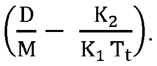
- Therefore, the vertical movement of the stack can go into sustained oscillations (e.g., self-excited third octave vibration) when the value of damping,

- The transit time variable (Tt) demonstrates why mill chatter can be associated with strip speed. As the mill speed rises, damping decreases and can become a negative value. Once the damping becomes negative, chatter can increase exponentially - assuming a linear system after chatter begins - until the strip breaks.
- Eliminating a mill's resonant chatter frequency may not be possible or required. The mechanical structure of each mill stand determines that stand's resonant frequency. Therefore, it can be desirable to limit and/or prevent any changes to the mill's natural damping.
- There are a number of possibilities for maintaining a positive level of damping as the inter-stand speed increases. Some possibilities are related to process changes that do not affect the product while others attempt to break the feedback loop between the work roll's vertical movement and inter-stand tension.
- With respect to the process related options, the value of K2 can be reduced in various ways. Reducing K2 can be accomplished by (1) reducing the inter-stand thickness to decrease the value of K2 by decreasing the impact of inter-stand tension on separating force, which can also have the effect of hardening the strip before it enters the second stand; (2) decreasing the inter-stand tension to increase the second stand's roll force, which can reduce the gain between separating force and exit thickness, further reducing the value of K2; and/or (3) increasing the friction at the entry of the second stand by increasing the surface roughness and/or changing the coolant's lubricity.
- Other methods for maintaining a positive level of damping as the inter-stand speed increases include increasing the value of K1, such as by shortening the extension of the roll force cylinder. The cylinder's stiffness may be greatest at each end of its stroke. Depending on the arrangement, the use of shim packs may be useful. These methods also include increasing the length of the strip between stands. Increasing the length will increase the minimum transit time (increase Tt). Some of these solutions may be impractical or economically prohibitive to implement.
- Active alternative methods to maintain positive damping include increasing the strip's elasticity as a function of frequency. If the strip appears to be very limber in the range of third octave frequencies, a change in the downstream stand's gap can produce a smaller change in tension with a corresponding smaller change in roll force. In effect, the value of K2 is reduced, thereby increasing the margin of stability.
- Some solutions can actively control mill vibration by measuring the mill vibration and directly changing the roll gap in anti-phase to the vibration. The performance of these systems can be highly dependent on accurate identification of the onset of third octave vibration, which may not be readily accomplished and can be inherently prone to error given the large number of different sources of mill vibration in the mill stand. These solutions also involve expensive and intrusive mechanical modifications to the mill gap regulator.
- Another active alternative for maintaining positive damping comprises rejecting tension disturbances that occur as a result of a gap change. Existing active control loops employed to maintain constant strip tension have a limited frequency range and allow tension disturbances in the third octave to pass through. Aspects of the present disclosure can be used to prevent tension disturbances in the third octave range. Preventing such tension disturbances can be equivalent to forcing the value of K2 to zero. By maintaining the entry tension at its target value, regardless of mill entry strip speed variations at the chatter frequency, self-excitation of the mill stack's resonant frequency by means of entry tension feedback loop can be mitigated, if not eliminated entirely.
- This approach can be advantageous over controlling the rolling gap to cancel self-excited third octave vibration. For example, a controller used for such approaches can be a high frequency extension of an existing tension regulator, and so may not involve the need for process identification with its attendant errors. Also, these approaches may not involve expensive and intrusive mill modifications. For example, a high frequency tension regulator can use a lower cost actuator outside the mill stand on the entry side of the roll gap, such as a modified bridle roll assembly.
- Certain aspects of the present disclosure relate to a two stand tandem cold mill comprising a center bridle roll and a control system designed to vary the vertical placement of the bridle roll in response to inter-stand strip tension disturbances occurring at a frequency of approximately 90-300 hertz, at a frequency of approximately 90-200 hertz, or at a frequency of approximately 90-150 hertz. Furthermore, the same concepts could be applied to correct other tension disturbances occurring at frequencies outside of the third octave mill vibration.
- The presence of an entry bridle at the entry of a stand offers an actuator to adjust tension of the strip as it enters the stand. For example, a second stand entry bridle may be used as a high speed strip storage mechanism (e.g., can store a length of strip around the center roll of the bridle, which can be let out or taken up as necessary to maintain constant tension) that can accommodate small changes in the downstream stand's strip entry speed. Such a storage mechanism may have much less mass (e.g., less than one ton) than a backup roll (e.g., at or over 60 tons) and can require much less energy in order to control chatter. An entry bridle can be used in conjunction with other equipment or processes for maintaining tension at frequencies outside of the self-excited third octave vibrations (e.g., at low frequencies, such as under 90 hertz or under 60 hertz).
- High-speed tension adjustors, such as the proposed bridle with adjustable center roller, can provide small changes in length at a very high speed (e.g., at or above 60 hertz or at or above 90 hertz). While these high-speed tension adjustors may not be able to accommodate significant changes in length, it is important that they are able to accommodate small changes in length at their high speeds. This compromise, speed versus distance, is noteworthy. At chatter frequencies, the strip storage requirements are not high, since storage is linked to the integral of velocity. In some cases, other high-speed tension adjustors can be used, such as hold down rolls, wiper blades, hydroplanes, magnetic tension adjustors. For example, a magnetic tension adjustor can include a rapidly rotating array of permanent magnets with the magnets aligned such that they impart a force at the frequency of third octave chatter, and in the direction to reduce the amplitude of the tension variation. For example, a 900 rpm rotor with eight axial rows of magnets could generate tension pulses at 120 Hz.
- The high-speed tension adjustors can be controlled by controllers. The controllers can be any suitable processor or system that can accept input from a sensor and determine the adjustments necessary for the high-speed tension adjustors. Any suitable sensor that can detect the onset of self-excited third octave vibration may be used. Example sensors include one or more sensor rolls (e.g., rolls with force transducers included therein or coupled thereto), stand-mounted sensors (e.g., accelerometers), or work roll or backup roll-mounted sensors (e.g., accelerometers). Other sensors can be used. The vibrations detected at the sensor can be used by the controller to determine the necessary adjustment for the high-speed tension adjustors such that the self-excited third octave vibration is canceled-out, reduced, stopped, or prevented.
- These illustrative examples are given to introduce the reader to the general subject matter discussed here and are not intended to limit the scope of the disclosed concepts. The following sections describe various additional features and examples with reference to the drawings in which like numerals indicate like elements, and directional descriptions are used to describe the illustrative embodiments but, like the illustrative embodiments, should not be used to limit the present disclosure. The elements included in the illustrations herein may not be drawn to scale.
-
FIG. 1 is a schematic side view of a four-high, two-standtandem rolling mill 100 according to certain aspects of the present disclosure. Themill 100 includes afirst stand 102 and asecond stand 104 separated by aninter-stand space 106. Astrip 108 passes through thefirst stand 102,inter-stand space 106, andsecond stand 104 indirection 110. Thestrip 108 can be a metal strip, such as an aluminum strip. As thestrip 108 passes through thefirst stand 102, thefirst stand 102 rolls thestrip 108 to a smaller thickness. As thestrip 108 passes through thesecond stand 104, thesecond stand 104 rolls thestrip 108 to an even smaller thickness. Thepre-roll portion 112 is the portion of thestrip 108 that has not yet passed through thefirst stand 102. Theinter-roll portion 114 is the portion of thestrip 108 that has passed through thefirst stand 102, but not yet passed through thesecond stand 104. Thepre-roll portion 112 is thicker than theinter-roll portion 114, which is thicker than a post-roll portion (e.g., portion of the strip after passing the second stand 104). - The
first stand 102 of a four-high stand can include opposing work rolls 118, 120 through which thestrip 108 passes.Force strip 108, by backup rolls 122, 124, respectively.Force Force strip 108, by backup rolls 134, 136, respectively.Force - The
mill 100 inFIG. 1 depicts multiple mechanisms for controlling self-excited third octave vibrations, including abridle roll 144 based mechanism to control self-excited third octave vibrations in thefirst stand 102 and ahydroplane 160 based mechanism to control self-excited third octave vibrations in thesecond stand 104. Any number or combination of mechanisms for controlling self-excited third octave vibrations can be used. - As seen in
FIG. 1 , thestrip 108 can pass through abridle 144 prior to entering thefirst stand 102. In some cases, thestrip 108 can be decoiled at a decoiler prior to passing through thebridle 144. Thebridle 144 can help maintain tension by adjusting the tension of thestrip 108 in response to fluctuations in strip tension. Thebridle 144 can include acenter roller 148 that is coupled to a high-speedlinear actuator 150. The high-speedlinear actuator 150 can be any suitable high-speed actuator, such as those as described herein, capable of manipulating thecenter roller 148 at speeds sufficient to control self-excited third octave vibrations. The high-speedlinear actuator 150 can directly manipulate the center roller 148 (e.g., two high-speed linear actuators can manipulate thecenter roller 148 at each end of the center roller) or the high-speedlinear actuator 150 can indirectly manipulate thecenter roller 148 by manipulating a yolk supporting thecenter roller 148. Any number of high-speedlinear actuators 150 can be used. - As third-octave vibration is detected by a sensor (e.g., a work roll-mounted
sensor 154 or a backup roll-mountedsensor 152, or another sensor), a controller can cause the high-speed actuator 150 to make adjustments to thecenter roller 148 to compensate for high-speed (e.g., in the third octave vibration range) increases or decreases in strip tension due to third octave vibration in thefirst stand 102. These adjustments can keep the strip tension in thepre-roll portion 112 relatively constant, at least in the third octave vibration range, to mitigate self-excited third octave vibrations. - In addition or alternatively, a
hydrofoil 160 can help maintain tension by adjusting the tension of thestrip 108 in response to fluctuations in strip tension. Thehydrofoil 160 can be semi-circular in shape or take on other shapes. Ahydrofoil 160 maintains a barrier of lubrication (e.g., with water or lubricant) between thehydrofoil 160 and thestrip 108, allowing thehydrofoil 160 to exert force on thestrip 108 without thehydrofoil 160 rotating. Since thehydrofoil 160 does not need to rotate, it can be manufactured with minimal material and minimal mass. For example, ahydrofoil 160 can have a semi-circular shape or semi-ovoid shape, rather than a fully circular shape of a roll. Thehydrofoil 160 can be coupled to one or more high-speedlinear actuators 162, such as similarly as a center roll of a bridle is coupled to one or more high-speed linear actuators (e.g., directly or via a yolk). The unique shape of thehydrofoil 160 can allow for one or more high-speedlinear actuators 162 to be coupled in other ways, such as anywhere along the width of the hydrofoil 160 (e.g., as opposed to just at the ends). - As third-octave vibration is detected by a sensor (e.g., a work roll-mounted
sensor 158 or a backup roll-mountedsensor 156, or another sensor), a controller can cause the high-speed actuator 162 to make adjustments to thehydrofoil 160 to compensate for high-speed (e.g., in the third octave vibration range) increases or decreases in strip tension due to third octave vibration in thesecond stand 104. These adjustments can keep the strip tension in theinter-roll portion 114 relatively constant, at least in the third octave vibration range, to mitigate self-excited third octave vibrations. - In some alternate cases, the roll gap of the
first stand 102 can be used to control tension in theinter-roll portion 114 in response to third-octave vibration detected by a sensor associated with the second stand 104 (e.g.,sensors 156, 158). In such cases, the rolls of thefirst stand 102 would not need to be moved to correct vibrations in thefirst stand 102, but rather the rolls would be adjusted to maintain constant tension between thefirst stand 102 and thesecond stand 104. -
FIG. 1 depictssensors sensor first stand 102 andsecond stand 104, respectively. However, sensors can be positioned on the bottom work rolls, bottom backup rolls, on the stand itself, or external to the stand. For example, a sensor can be positioned between thebridle 144 and thefirst stand 102. Such a sensor can be a sensor roll (e.g., a roll supported by a pair of force transducers to measure high-speed changes in strip tension). In some cases, other sensors can be used, such as ultrasonic, laser, or other sensors capable of detecting third octave vibration. - In some cases, the
third roller 164 of thebridle 144 can act as a sensor. Thethird roller 164 can include internal force sensors. In some cases, thethird roller 164 can be coupled to one ormore load cells 166. For example, a pair ofload cells 166 can be placed on opposite ends of thethird roller 164. Theload cells 166 can detect tension fluctuation in the third octave range. -
FIG. 2 is a schematic diagram depicting amill 200 having multiple high-speed tension adjustors metal strip 224 can pass through various parts from left to right, as seen inFIG. 2 . Items to the left can be considered proximal to or upstream of items further to the right. For example,first stand 208 can be considered proximal to or upstream of thesecond stand 216. - The
metal strip 224 can be decoiled at adecoiler 202. Themetal strip 224 can pass through afirst stand 208 and asecond stand 216. While two stands are shown inFIG. 2 , any number of stands, including one stand or more than two stands, can be used. The adjustments made between thefirst stand 208 and thesecond stand 216 can be used between any two stands of a multi-stand mill (e.g., between a second and third stand). The adjustments made between thedecoiler 202 and thefirst stand 208 can be used on a single-stand mill. - As the
metal strip 224 moves from thedecoiler 202 to thefirst stand 208, it can pass through a high-speed tension adjustor 204. The high-speed tension adjustor 204 can be any adjustor as described herein, including a bridle with movable center roller, a hydrofoil, a wiper, or a magnetic system. Other high-speed tension adjustors can be used. The high-speed tension adjustor 204 can receive adjustment signals from acontroller 220 based on vibrations detected in thestrip 224 between the high-speed tension adjustor 204 and thefirst stand 208 or at thefirst stand 208. Thecontroller 220 can receive signals from a sensor, such assensor 206 orsensor 210.Sensor 206 can be a sensor placed inline between the high-speed tension adjustor 204 and thefirst stand 208.Sensor 206 can be any suitable sensor, such as but not limited to a deflection roll (e.g., flatness roll) coupled to one or more load cells.Sensor 210 can be a sensor, such as but not limited to an accelerometer, coupled to thefirst stand 208, such as on a work roll, backup roll, roll chock, or stand itself. Whensensor 210 is an accelerometer, it can be tuned to only detect vertical motion of the rolls. In some cases,sensor 210 can include multiple sensors (e.g., positioned on the top and bottom work rolls) configured to detect vertical motion of the top work roll with respect to the bottom work roll. Other sensors can be used. - Upon receiving signals indicative of third octave vibrations, the
controller 220 can induce high-speed tension adjustment using the high-speed tension adjustor 204. The tension adjustments can be calculated to offset or cancel out the detected or expected vibration in thefirst stand 208. In some cases, random tension adjustments can be induced. - In some cases, a
controller 220 can be a processor or any type of digital and/or analog circuitry. In some cases, acontroller 220 can be a collection of hydraulic conduits, chambers, and actuators designed to function as described herein. - The high-
speed tension adjustor 204 can reject high frequency (e.g., third octave) strip tension disturbances. The high-speed tension adjustor 204 therefore must be able to move at a rate fast enough to store the accumulatedstrip 224 per each cycle of chatter. The height of a work roll in a stand (e.g., the first stand 208) can be tightly regulated at low frequencies (e.g., well below third octave frequencies) and general tension can be controlled by other mechanisms, such as by controlling the difference in speed between a first stand and a second stand, as well as the gap of the first stand. At chatter frequencies, however, the average roll height (e.g., distance between the top work roll and bottom work roll) can deviate. Thecontroller 220 can focus on controlling the disturbances in the frequency band corresponding to self-excited third octave vibration. To ensure that thecontroller 220 has sufficient range of action, tension disturbances outside this frequency range can be rejected from the signal used to drive the high-speed tension adjustor 204, such as using some combination of signal filtering. - As the
metal strip 224 passes from thefirst stand 208 to thesecond stand 216, its tension can be adjusted to reject third octave vibration in thesecond stand 216. Acontroller 222 can receive signals, similar tocontroller 220, from one or more sensors, such assensor 214 andsensor 218.Sensor 214 can be similar tosensor 206, but positioned between thefirst stand 208 andsecond stand 216.Sensor 218 can be similar tosensor 210, but positioned on thesecond stand 216. Other sensors can be used. Similarly to high-speed tension adjustor 204, high-speed tension adjustor 212 can be positioned between thefirst stand 208 andsecond stand 216 to control tension in the third octave range based on signals fromcontroller 222. In some cases, however,controller 222 can send signals to thefirst stand 208 to control the roll gap in thefirst stand 208, thus effectively controlling the speed with which thestrip 224 enters the inter-stand region, thus controlling the effective tension of thestrip 224 in the inter-stand region. In some cases,controller 222 can send signals to any combination of one or more of thefirst stand 208 and high-speed tension adjustor 212. In some cases, the functions ofcontroller 222 andcontroller 220 are performed by a single controller. - The high-
speed tension adjustors strip 224 to maintain constant tension despite third octave vibration at thefirst stand 208 orsecond stand 216. The chatter frequency determines the amount of strip storage needed to prevent feedback due to fluctuating strip tension. For example, given a strip velocity as a function of time, Vstrip = A sin 2πfct, where fc is the chatter frequency in hertz and A is the amplitude of speed variation, then the maximum storage required is shown below in Equation 2.
- Mills generally chatter in the neighborhood of 90-300 hertz, and more particularly in the neighborhood of 90-200 hertz or 90-150 Hz. Since the lower frequency requires more storage, this value (e.g., 90 Hz) can be used to calculate the largest amount of strip storage length that would be needed. Such a value can be used to set the strip storage length in a high-
speed tension adjustor speed tension adjustor - Once the third octave frequency range is established, the value of 'A' needs to be defined to determine the maximum strip storage length. The value of A depends on the amount of gauge variation that is acceptable in a rolled strip. In an example, in some circumstances, if chatter causes a gauge variation of approximately 1%, the resultant damage can cause the strip to be rejected as scrap. Other percentages of gauge variation can be used, depending on the needs of the rolled strip and other factors. For the purposes of this example, the maximum entry strip speed variation will be 1%. For a two stand tandem mill rolling canned beverage stock (CBS) at 2000 meters per minute (MPM), the inter-stand speed can be no more than approximately 1000 MPM. The value of 'A' can then be 10 MPM (a gauge variation will cause a 1% change in velocity, conservation of mass flow through gap) or 0.16666 meters per second (MPS). The amount of storage required at 90 hertz for this example can therefore be approximately 0.60 mm, because StripStoragemax =

speed tension adjustor 204 must be able to displace approximately 0.60 mm at a speed of 90 Hz. - The above calculations can be adjusted as necessary for other examples. The above calculations can also be leveraged by a controller in order to drive a high-speed tension adjustor as necessary.
-
FIG. 3 is an isometric diagram depicting a third octavevibration control system 300 with a yolk-controlledbridle 304 according to certain aspects of the present disclosure. Ametal strip 302 passes through abridle 304 and into amill stand 308 having atop work roll 310 and abottom work roll 312. Thecenter roll 306 of thebridle 304 acts as a high-speed tension adjustor. As thecenter roll 306 is manipulated downwards and upwards,metal strip 302 is stored or released, respectively, from around a portion of the circumference of thecenter roll 306. Thecenter roll 306 can be supported by ayolk 314. Upwards or downwards movement of thecenter roll 306 can be achieved by manipulation of alinear actuator 316 coupled to theyolk 314. In some cases, more than onelinear actuator 316 can be coupled to theyolk 314. Any suitablelinear actuator 316 can be used, such as a hydraulic cylinder and/or a piezoelectric actuator. The plunge depth of thecenter roll 306 can be adjustable via a movable stop on a main hydraulic cylinder. The one or morelinear actuators 316 can adjust the movable stop of the main hydraulic cylinder, thus adjusting the plunge depth of thecenter roll 306. - The bridle's
center roll 306 can thus alter the path of themetal strip 302 before it enters astand 308. Changing the stiffness of this nesting mechanism (e.g., adjustments to the movable stop of the main hydraulic cylinder) at high frequencies (e.g., third octave vibrations) can mitigate any tension variation resulting from the downstream stand's gap movement. - In cases where a linear actuator manipulates the yolk 314 (e.g., manipulates the
yolk 314 itself or adjusts the end stops of the yolk 314), no differential tilt control loop may be necessary because theyolk 314 movement can be constrained by a rack and pinion assembly that maintains the side-to-side elevation of theyolk 314. -
FIG. 4 is an isometric diagram depicting a third octavevibration control system 400 with an end-controlledbridle 404 according to certain aspects of the present disclosure. Ametal strip 402 passes through abridle 404 and into amill stand 408 having atop work roll 410 and abottom work roll 412. Thecenter roll 406 of thebridle 404 acts as a high-speed tension adjustor. As thecenter roll 406 is manipulated downwards and upwards,metal strip 402 is stored or released, respectively, from around a portion of the circumference of thecenter roll 406. Thecenter roll 406 can be supported by a pair oflinear actuators linear actuators center roll 406. Any suitablelinear actuators linear actuators - In some cases, such end-mounted
linear actuators yolk 414, which can be actuated by another linear actuator. In such cases, thelinear actuators center roll 406 to move vertically separately from the nesting mechanism (e.g., yolk 414). Use of such end-mountedlinear actuators yolk 414 and associated driving equipment) from the total mass necessary to be manipulated in order to control chatter. The use of end-mountedlinear actuators strip 406. In some cases, sensors and a control loop can be used to minimize, if not eliminate, tilt. - As described above with reference to
FIGs. 3-4 , center rolls 306, 406 can be manipulated usinglinear actuators linear actuators FIGs. 3-4 , thelinear actuators - In some cases, tension can be measured by means of load cells supporting the
third bridle roll 320, 420 (closest to the mill bite). Tension can be measured by other sensors, as described elsewhere herein. - When a hydraulic linear actuator is used, the bore of the hydraulic linear actuator can be determined based on various factors, including maximum load necessary to maintain strip tension and minimized hydraulic fluid (e.g., oil) flow. In an example, a strip having a cross-sectional area of approximately 1600 mm2, with a tension of approximately 20 N/mm2 (20 MPa), with a geometry of 2:1 (e.g., center roll wrap angle of 180° - the amount of strip stored in the bridle for displacement of the work rolls), the maximum load needed to maintain strip tension can be Fcyl = 2 ∗ 20 ∗ 1600 = 64 KN. To minimize hydraulic fluid flow, the supply pressure can be defined to be approximately 27.5 MPa. Allowing for a bore pressure of 14 N/mm2, the cylinder area required can be Acyl = 64000/14 = 4600 mm2. In this example, two hydraulic linear actuators can be located at each end of the roll to support the roll's vertical position (e.g., as seen in
FIG. 4 ). The wrap angle on the first roll of the bridle is assumed to be approximately 90° as the strip's path goes from horizontal to vertical and passes under the center roll. Using a wrap angle of approximately 180° around the center roll of the bridle, the maximum vertical force can be approximately 64 KN. Again the maximum bore pressure can be half the supply pressure, yielding a cylinder area of 4600 mm2. In this case however, the area is divided between two cylinders. The required bore size of each is approximately 54 mm. It can be desirable to round up to 60 mm (2827 mm2) to provide an additional margin of safety. Similar calculations can be made for a singlelinear actuator 316 or for other circumstances (e.g., other sizes and types of metal sheet). - The stroke length of a hydraulic linear actuator can be determined based on various factors. Each cylinder stroke can be set to allow for the maximum storage per cycle. In an example, given a wrap angle of approximately 180° and a strip storage requirement of approximately 0.60 mm, the cylinder stroke can be reduced to approximately 0.30 mm. Adding some margin for error, a minimum stroke 2 mm can be used required.
- The hydraulic linear actuator can be actuated by a servo-valve. In such cases, the servo-valve necessary for the hydraulic linear actuator can be determined based on various factors. For example, the servo-valve can be selected to be able to control the height of the center roll at 30 hertz (lower frequency tension disturbances are controlled by other actuators) while allowing the roll to move at the higher chatter frequencies. The worst case flow rate can be at the highest frequency of chatter (e.g., approximately 150 hertz or 200 Hz or 300 Hz). In some cases, the servo-valve can have the speed to hold the target strip tension as the length of strip between the stand and a preceding device (e.g., preceding stand or a decoiler) changes. In such an example, the change in length at the chatter frequency can be used as a guideline. Assuming an acceptable gauge variation of approximately 1% at 90 hertz, the target cylinder travel can be set at approximately 0.33 mm. Therefore, at 150 hertz, a flow rate of 48 lpm will be required (Qv = 2827 mm ∗ 0.30 mm ∗ 2π ∗ 150 ∗ 60 /1e6 = 48 lpm. The servo-valve required can be thusly selected. An example suitable servo-valve for a hydraulic-cylinder-based high-speed tension adjustor can be a MoogTM valve type D765 HR/38 lpm which can supply 40% (15.2 lpm) at a frequency of approximately 150 hertz. If the pressure drop is maintained at approximately 14 MPa, the flow rate is approximately 21.43 lpm. This design can use two valves on each hydraulic linear actuator to meet the flow requirements.
- A high-speed tension adjustor can be controlled in various ways. In one example, the control strategy can be to create a position control loop around a fast tension loop. The position loop can set the average extension of the hydraulic actuator at half the hydraulic actuator's maximum extension (e.g., approximately 1 mm). The response of the position loop holding the hydraulic actuator's position fixed is approximately 30 hertz, which makes the hydraulic actuator very stiff up to approximately 30 hertz. The position controller supplies the pressure loop with a pressure reference. Therefore, the tension reference is a function of the load applied to the roll.
- The inner tension loop can have a much higher response, such as approximately 150 hertz. Its purpose can be to allow the roll to move vertically as the applied load of the strip varies. As the tension varies due to load swings, the tension controller adds and subtracts small amounts of fluid to maintain the pressure reference supplied by the position controller.
- When the linear actuator is a hydraulic linear actuator, the hydraulic components can be located below the
strip 302, which can be advantageous for feeding thestrip 302 during threading. Whenlinear actuators - In some cases, one or more piezoelectric actuators can be used to adjust the height of a yolk 314 (e.g., a frame). Specifically, the piezoelectric actuator can be positioned to vary the height of the center bridle roll frame's adjustable end stop. The positioning of the end stop can set the plunge depth of the
center roll 306. In some cases, a piezoelectric actuator capable of moving the frame can be located on top of each side's end stop assembly. The vertical movement of the center roll's frame (e.g., yolk 314) can be used to maintain a constant strip tension. In such cases, instead of moving thecenter roll 306 directly (e.g., as seen inFIG. 4 ), the piezoelectric actuators move theentire center roll 306 by moving theyolk 314. The piezoelectric actuators can be the same, but may require two or more units in parallel to handle the compression force supplied by the cylinder. In some cases, maintaining strip tension can require an actuator force equal to the applied tension force as well as the force needed to accelerate the frame vertically. For example, assuming that the weight of the roll assembly and frame is approximately 1500 Kgf and an acceleration rate of approximately 139 mm/sec2 (180 µm @140 hertz), this acceleration force is approximately 21.3 KN. - In some case, the components can be mounted in a fixed position and located far away from the strip.
-
FIG. 5 is a partial-cutaway view of alinear actuator 500 including ahydraulic actuator 502 with apiezoelectric assist 504 according to certain aspects of the present disclosure. Thelinear actuator 500 can be used for any of the linear actuators disclosed herein, such aslinear actuators FIGS. 3-4 . Thelinear actuator 500 includes ahydraulic actuator 502 consisting of a main body supporting apiston 512 therein. The main body includes a drivingcavity 516 into which hydraulic fluid can be circulated to manipulate thepiston 512. - The
piezoelectric assist 504 can include anassist body 510 coupled to thehydraulic actuator 502 by achannel 514. Theassist body 510 can include one or morepiezoelectric devices 506 coupled to adiaphragm 508. As an electrical current is applied to the one or morepiezoelectric devices 506, eachpiezoelectric device 506 can deform to push thediaphragm 508 indirection 518. Thediaphragm 508 can thus push hydraulic fluid into the drivingcavity 516 through thechannel 514, thus forcing thepiston 512 indirection 520. Removing the electrical current or applying a reverse current can cause eachpiezoelectric device 506 to deform in an opposite direction, pulling ondiaphragm 508, causing thepiston 512 to move in a direction opposite ofdirection 520. - Because
piezoelectric devices 506 can operate at very high frequencies, thepiezoelectric assist 504 can increase the speed with which ahydraulic actuator 502 can function. A singlehydraulic actuator 502 can include one or morepiezoelectric assists 504. - In an example, with two hydraulic actuators positioned at the ends of a center roll (e.g., as seen in
FIG. 4 ), each hydraulic actuator can be a hydraulic cylinder having a bore size of 60 mm with a minimum cylinder stroke of 2 mm. Similar to when no piezoelectric assist is used, the servo-valve must be able to control the height of the center roll at 30 hertz, while allowing the roll to move at the chatter frequency. However, unlike when no piezoelectric assist is used, in this example, this requirement is restricted to frequencies up to 30 hertz. - In this example, the change in length at the chatter frequency can be used as a guideline, with a gauge variation of 1% at 30 hertz giving a target strip storage of 1.76 mm. If the roll's wrap angle is approximately 180°, the vertical movement can be reduced to 0.88 mm. At 30 hertz, a flow rate of approximately 23 lpm is required (e.g., Qv= 2827 mm ∗ 0.88 mm ∗ 2π ∗ 30 ∗ 60 / 1e6 = 28 lpm). In this example, a servo-valve can be selected capable of supplying the appropriate flow rate. For example, a MoogTM valve type D765 HR/38 lpm can supply 100% at a frequency of 30 hertz. In this example, the valve is not tasked with controlling the fluid flow at the chatter frequency. High frequency load variations can be left to the piezoelectric actuator.
- The hydraulic actuator can be used to hold the average height of the center roll at a constant level at mid stroke of the hydraulic cylinder. Force variations at the chatter frequency will have no effect since the stiffness of the two cylinders combine to be much greater than the strip.
- To accommodate high frequency tension disturbances, the piezoelectric actuator can be placed between the valve and the cylinder. The piezoelectric assist can change the volume of hydraulic fluid as a function of hydraulic fluid pressure. The length of the piezoelectric device changes as the pressure varies.
- Since piezoelectric actuators change length by only approximately 0.1%, inserting such a device in line with the cylinder can be impractical. A 50 mm long piezoelectric will move approximately 0.05 mm. Instead, the piezoelectric device can be housed in a cylinder with a larger area. In an example, the cylinder housing the piezoelectric device can have an area of approximately 5 times the area of the hydraulic cylinder (e.g., 14,135 mm2) capable of holding a number of piezoelectric devices (e.g., 50 mm long piezoelectric devices). In an example, by using a number of such piezoelectric devices having a surface area of approximately 15,000 sq. mm, to change the volume of oil by 706 mm3, the resulting change in length on the working cylinder is approximately (706 mm3/2827mm2), or 0.25 mm.
- The
linear actuator 500 withpiezoelectric assist 504 can be controlled using any suitable strategy. In an example control strategy, a simple single degree of freedom position control loop is created. The position loop can set the average extension of the hydraulic cylinder at half the hydraulic cylinder's maximum extension (e.g., approximately 1 mm). The response of the position loop can be 30 hertz, which can make the cylinder very stiff up to 30 hertz. - While the position control loop indirectly drives the cylinder's average pressure to maintain a target extension, a separate controller can monitor the tension in the frequency range associated with chatter (e.g., third octave vibrations, such as 90-300 Hz). The separate controller can allow the roll to move vertically as the applied load of the strip varies. As the combined pressure of both hydraulic cylinders varies due to load swings, the controller can use the piezoelectric actuator(s) to change the total volume of oil in the assembly. In an example, this action can create a movement of 0.25 mm, which can be large enough to handle a change in entry strip speed.
- In some cases, the use of a piezoelectric assist can eliminate any need for a fast, independent, tilt control loop. In some cases, there can be less dependency on the performance of the servo-valve since the frequency range of the piezoelectric device often exceeds a servo-valve's flow performance. In some cases, a hydraulic circuit may be used to maintain a pressure differential on the piezoelectric side of the diaphragm. In some cases, strip tension may be used as a feedback variable. Under certain conditions, fluid pressure alone could produce some error due to the acceleration force required to move the center roll.
-
FIG. 6 is a partial cutaway, isometric view of a high-speed tension adjustor 600 withpiezoelectric actuators 604 according to certain aspects of the present disclosure. Aroll chock 606 can support acenter roll 602 of a bridle. In some cases, a different deflecting device is used instead of acenter roll 602, such as a hydroplane or wiper. - A
piezoelectric actuator 604 can couple theroll chock 606 to asupport 608. In some cases, thesupport 608 can be a yolk supporting theentire center roll 602. Electrical current applied to thepiezoelectric actuator 604 can cause thepiezoelectric actuator 604 to deform by extending or retracting, thus moving thecenter roll 602 upwards or downwards. As seen inFIG. 6 , thecenter roll 602 can be supported by twopiezoelectric actuators 604, one on each side. Eachpiezoelectric actuator 604 can include one or more individual piezoelectric devices mechanically arranged in parallel or series with one another to produce the desired movement in thecenter roll 602. The vertical movement of thecenter roll 602 is used to maintain a constant strip tension. - In some cases, a single piezoelectric device is capable of changing length by approximately 0.1% to 0.15% at full voltage and can generate a force in the range of 30MPa per mm2. For example, a commercially available standard piezoelectric stack having a diameter of approximately 56 mm and a length of approximately 154 mm can produce a blocking force of approximately 79KN and a change in length of approximately 180 µm.
- Maintaining strip tension can require an actuator force equal to the applied tension force, as well as the force needed to accelerate the
center roll 602 vertically (e.g., which can be reduced by using a hydrofoil or other deflector having a smaller mass than a center roll 602). For example, assuming that the weight of thecenter roll 602 assembly is approximately 500 Kgf and an acceleration rate of approximately 139 mm/sec2 (180 µm @140 hertz), this acceleration force is approximately 7.1 KN. - In some cases, the length of the
piezoelectric actuator 604 is maximized to deliver the largest change in length available. - Controlling
piezoelectric actuators 604 can be done in any suitable fashion. In one example, the control strategy includes creating a strip tension control loop. The total strip tension feedback is measured by sensors (e.g., load cells mounted at each end of an adjacent bridle roll, such as the roll closest to the work rolls). A controller can drive thepiezoelectric actuators 604 to maintain the target strip tension. A differential control loop can maintain differential tension (side-to-side) as close to zero as possible. - In some cases, a controller with a fast execution rate (e.g., at or around 100 µsec or faster) can be used. A combination of a digital and analog control can be used. In some cases, a high current driver can be used. In some cases, piezoelectric devices can be selected that offer at least a 0.15% change in length.
- The use of only
piezoelectric actuators 604 in a high-speed tension adjustor can eliminate the need for many moving parts and hydraulic parts. -
FIG. 7 is a flow chart depicting aprocess 700 for controlling vibration in a mill according to certain aspects of the present disclosure. Atblock 702, tension fluctuations are detected. Tension fluctuations can be detected by any suitable sensor, such assensors FIG. 1 ;load cell 166 inFIG. 1 ; or any other suitable sensor. These detected tension fluctuations can be sent to a controller in the form of a measured fluctuations signal. - At
optional block 704, the measured fluctuations signal can be filtered to remove any detected tension fluctuations outside of the third octave range (e.g., outside of the 90-300 Hz range, 90-200 Hz range, or 90-150 Hz range). In some cases, other ranges besides the third octave range can be used. - At block 706, the tension adjustment can be determined. The tension adjustment can be based on a simple feedback-control loop based on the measured fluctuations signal or the filtered signal. In some cases, the tension adjustment can be calculated to maximize the interference of the applied tension adjustment with the measured strip tension fluctuations. The resultant tension adjustment can be transmitted as a tension adjustment signal.
- At block 708, the tension adjustment can be applied using the tension adjustment signal. The tension adjustment signal can be sent to drivers or directly to the linear actuators of a high-speed tension adjustor. The tension adjustments made by the high-speed tension adjustor(s) can help maintain constant strip tension and can reduce the third octave vibrations in a metal strip and/or in a mill stand.
- The use of
process 700 can inject tension disturbances to reduce self-excited vibration, such as in the third octave range.Process 700 can be performed using any of the various systems and assemblies described herein, including inFIGs. 1-6 .Process 700 can be applied before a strip enters a mill stand or between mill stands. In some cases, the use ofprocess 700 can allow mill stands to roll at a greater speed than withoutprocess 700. Additionally, without the worry of self-excited third octave vibrations, mills can operate longer and faster with less scrap (e.g., scrap due to self-excited third octave vibrations). Significant savings of time, money, and resources can be achieved usingprocess 700. -
FIG. 8 is a cross-sectional view of ahydraulic actuator 800 withpiezoelectric assists 814 in an extended state according to certain aspects of the present disclosure. Thehydraulic actuator 800 can be any hydraulic actuator, such as those disclosed herein with reference toFIGs. 1 ,3, and 4 . Thehydraulic actuator 800 can include acylinder body 802 supporting apiston 804 therein. Thecylinder body 802 includes a driving cavity 808 (e.g., fluid chamber) into whichhydraulic fluid 806 can be circulated to manipulate thepiston 804.Hydraulic fluid 806 can be circulated by a hydraulic driver 826 (e.g., servo-valves and/or other parts) controllable by controller 824 (e.g., such ascontrollers FIG. 2 ).Hydraulic fluid 806 can be circulated throughcylinder ports piston 804. - The
piston 804 can include apiston head 828 having one or more recesses 830. Piezoelectric assists 814 can be located within eachrecess 830. In some cases,multiple recesses 830 can be spread across theentire piston head 828 in order to maximize an amount of surface area actuatable by the piezoelectric assists 814. In alternate cases, piezoelectric assists can be located elsewhere besides the piston head as long as the piezoelectric assist is able to change the volume of the drivingcavity 808. - As seen in
FIG. 8 , eachpiezoelectric assist 814 includes a piezoelectric device 832 (e.g., a piezoelectric stack) coupled to asub-piston 816. The sub-piston 816 acts like a piston within therecess 830, moving axially to adjust the position of anend plate 834.Multiple sub-pistons 816 can act on asingle end plate 834 in order to provide more actuation force. In some cases, noend plate 834 is used ormultiple end plates 834 are used. Movement of thesub-pistons 816 can cause change in the volume of the drivingcavity 808, such as through movement of anend plate 834. - As an electrical current is applied to a
piezoelectric device 832, thepiezoelectric device 832 can deform to either extend or retract, thus pushing or pulling on thesub-piston 816, which can then push or pull on theend plate 834. Opposite electrical current can be applied to deform thepiezoelectric device 832 in the opposite direction. When the piezoelectric assists 815 are in an extended state, they have decreased the volume of the drivingcavity 808. - Wiring 818 can couple each
piezoelectric device 832 tocontroller 824 through awiring port 820. Optionally, a piezoelectric driver can drive thepiezoelectric devices 832 and the piezoelectric deriver can be controlled by thecontroller 824. An internal recess of thepiston 804 can be covered by anend cap 822, which is coupled to thepiston 804. - Because
piezoelectric devices 832 can operate at very high frequencies, thepiezoelectric assist 814 can increase the speed with which ahydraulic actuator 800 can function. A singlehydraulic actuator 800 can include one or morepiezoelectric assists 814. - To accommodate high frequency tension disturbances, the piezoelectric actuator can be placed between the valve and the cylinder. The piezoelectric assist can change the volume of hydraulic fluid as a function of hydraulic fluid pressure. The length of the piezoelectric device changes as the pressure varies.
-
FIG. 9 is a cross-sectional view of thehydraulic actuator 800 ofFIG. 8 withpiezoelectric assists 814 in a retracted state according to certain aspects of the present disclosure. Actuation of thepiezoelectric devices 832 within thepiezoelectric assists 814 can force thesub-pistons 816 to retract into therecesses 830 of thepiston head 828, thus reducing the effective volume of the drivingcavity 808. When anend plate 834 is used, retraction of thesub-pistons 816 cause retraction of theend plate 834, thus reducing the effective volume of the drivingcavity 808. - When the sub-pistons 816 retract to reduce the effective volume of the driving
cavity 808, thepiston 804 andend cap 822 must move inwards with respect to the cylinder body 802 (e.g., upwards inFIGs. 8-9 ), especially when thehydraulic fluid 806 is incompressible.Hydraulic fluid 806 can be allowed to flow between thecylinder ports cylinder body 802. Thecontroller 824 can continue to control thehydraulic driver 826 and can control thepiezoelectric devices 832 viawiring 818 through theelectrical port 820. - This small amounts of linear movement achieved through actuation of the
piezoelectric assists 814, such as between an extended state (e.g.,FIG. 8 ) and a retracted state (e.g.,FIG. 9 ) can occur at extremely fast speeds (e.g., at or above approximately 90 hertz). Because thepiezoelectric assists 814 are positioned between thehydraulic fluid 806 and thepiston 804, movement ofhydraulic fluid 806 is minimal in order to effectuate movement of thepiston 804. - Different arrangements of the components depicted in the drawings or described above, as well as components and steps not shown or described are possible. Similarly, some features and sub-combinations are useful and may be employed without reference to other features and sub-combinations.
- The foregoing description of the embodiments, including illustrated embodiments, has been presented only for the purpose of illustration and description and is not intended to be exhaustive or limiting to the precise forms disclosed. Numerous modifications, adaptations, and uses thereof will be apparent to those skilled in the art.
- As used below, any reference to a series of examples is to be understood as a reference to each of those examples disjunctively (e.g., "Examples 1-4" is to be understood as "Examples 1, 2, 3, or 4").
- Example 1 is a two (or more) stand tandem cold mill comprising between stands: a tension adjustment device selected from the group consisting of a center bridle roll, an actuated deflection roll, or an actuated sheet wiper; and a control system designed to vary vertical placement of the tension adjustment device in response to inter-stand strip tension disturbances occurring at a frequency of third octave mill stand resonance typically in the range of approximately 90-300 hertz.
- Example 2 is the mill of example 1, wherein the control system comprises at least two hydraulic cylinders located proximate each end of the tension adjustment device, and a controller having a position control loop and a fast tension loop, wherein the fast tension loop is configured to vary vertical placement of the tension adjustment device in response to tension disturbances occurring at the frequency of third octave mill stand resonance typically in the range of approximately 90-150 hertz, and the position control loop is configured to maintain the vertical placement of the tension adjustment device in response to tension disturbances occurring at lower frequencies.
- Example 3 is the mill of example 1, wherein the control system comprises at least two hydraulic cylinders located proximate each end of the tension adjustment device, a plurality of piezoelectric actuators positioned between each of the at least two hydraulic cylinders and the tension adjustment device, and a controller having a position control loop and a separate controller, wherein the separate controller is configured to vary vertical placement of the tension adjustment device in response to tension disturbances occurring at the frequency of third octave mill stand resonance typically in the range of approximately 90-300 hertz, and the position control loop is configured to maintain the vertical placement of the tension adjustment device in response to tension disturbances occurring at lower frequencies.
- Example 4 is the mill of example 3, wherein the frequency of third octave mill stand resonance is typically in the range of approximately 90-200 hertz.
- Example 5 is the mill of example 1, wherein the control system comprises at least two piezoelectric stacks located proximate each end of the tension adjustment device, and a controller having a strip tension control loop configured to vary vertical placement of the tension adjustment device in response to tension disturbances occurring at the frequency of third octave mill stand resonance typically in the range of approximately 90-300 hertz.
- Example 6 is the mill of example 5, wherein the frequency of third octave mill stand resonance is typically in the range of approximately 90-200 hertz.
- Example 7 is the mill of example 1, wherein the control system comprises at least two piezoelectric stacks, each piezoelectric stack being located on an upper surface of an adjustable end stop on each side of a center frame supporting the tension adjustment device, and a controller having a strip tension control loop configured to vary vertical placement of the tension adjustment device in response to tension disturbances occurring at the frequency of third octave mill stand resonance typically in the range of approximately 90-300 hertz.
- Example 8 is the mill of example 7, wherein the frequency of third octave mill stand resonance is typically in the range of approximately 90-200 hertz.
- Example 9 is a single stand mill comprising: an uncoiler positioned upstream of the mill stand; a tension adjustment device selected from the group consisting of a center bridle roll, an actuated deflection roll, or an actuated sheet wiper; and a control system designed to vary vertical placement of the tension adjustment device in response to tension disturbances between the uncoiler and the mill stand.
- Example 10 is the mill of example 9, wherein the control system comprises at least two hydraulic cylinders located proximate each end of the tension adjustment device, and a controller having a position control loop and a fast tension loop, wherein the fast tension loop is configured to vary vertical placement of the tension adjustment device in response to tension disturbances occurring at the frequency of third octave mill stand resonance typically in the range of approximately 90-150 hertz, and the position control loop is configured to maintain the vertical placement of the tension adjustment device in response to tension disturbances occurring at lower frequencies.
- Example 11 is the mill of example 9, wherein the control system comprises at least two hydraulic cylinders located proximate each end of the tension adjustment device, a plurality of piezoelectric positioned between each of the at least two hydraulic cylinders and the tension adjustment device, and a controller having a position control loop and a separate controller, wherein the separate controller is configured to vary vertical placement of the tension adjustment device in response to tension disturbances occurring at the frequency of third octave mill stand resonance typically in the range of approximately 90-300 hertz, and the position control loop is configured to maintain the vertical placement of the tension adjustment device in response to tension disturbances occurring at lower frequencies.
- Example 12 is the mill of example 11, wherein the frequency of third octave mill stand resonance is typically in the range of approximately 90-200 hertz.
- Example 14 is the mill of example 9, wherein the control system comprises at least two piezoelectric stacks located proximate each end of the tension adjustment device, and a controller having a strip tension control loop configured to vary vertical placement of the tension adjustment device in response to tension disturbances occurring at the frequency of third octave mill stand resonance typically in the range of approximately 90-300 hertz.
- Example 14 is the mill of example 13, wherein the frequency of third octave mill stand resonance is typically in the range of approximately 90-200 hertz.
- Example 15 is the mill of example 9, wherein the control system comprises at least two piezoelectric stacks, each piezoelectric stack being located on an upper surface of an adjustable end stop on each side of a center frame supporting the tension adjustment device, and a controller having a strip tension control loop configured to vary vertical placement of the tension adjustment device in response to tension disturbances occurring at the frequency of third octave mill stand resonance typically in the range of approximately 90-300 hertz.
- Example 16 is the mill of example 15, wherein the frequency of third octave mill stand resonance is typically in the range of approximately 90-200 hertz.
- Example 17 is a system, comprising a tension adjustor positionable proximal an entrance of a mill stand for adjusting tension of a metal strip entering the mill stand; a sensor for measuring tension fluctuations at or above 90 hertz of the metal strip entering the mill stand; and a controller coupled to the sensor and the tension adjustor for actuating the tension adjustor to adjust the tension of the metal strip in response to the measured tension fluctuations.
- According to the invention, example 18 is the system of example 17, wherein the tension adjustor includes a deflection device capable of storing a length of the metal strip and at least one actuator for manipulating the deflection device to change the stored length of metal strip at speeds at or above approximately 90 hertz.
- Example 19 is the system of example 18, wherein the deflection device is selected from the group consisting of a center roll of a bridle, a deflection roll, a sheet wiper, and a hydroplane.
- Example 20 is the system of examples 18 or 19, wherein the at least one actuator is a pair of linear actuators positioned on opposite ends of the deflection device.
- Example 21 is the system of examples 18 or 19, wherein the at least one actuator is coupled to the deflection device through a yolk.
- Example 22 is the system of examples 18 or 19, wherein each of the at least one linear actuators is a piezoelectric actuator.
- Example 23 is the system of examples 18 or 19, wherein each of the at least one linear actuators is a hydraulic actuator.
- Example 24 is the system of example 23, wherein each of the at least one linear actuators further comprises a piezoelectric assist coupled to the hydraulic actuator.
- According to the invention, example 25 is the system of examples 17-24, wherein the sensor is coupled to the mill stand for detecting vibrations indicative of the tension fluctuations of the metal strip.
- Example 26 is the system of examples 17-24, wherein the sensor is at least one load cell coupled to a roller positionable proximal the mill stand.
- Example 27 is a cold-rolling mill, comprising a mill stand having a top work roll and a bottom work roll between which a metal strip can be passed; a tension adjustor positionable upstream of the mill stand for adjusting tension of the metal strip as the metal strip enters the mill stand; a sensor positionable on or adjacent the mill stand for detecting vibrations indicative of self-excited third octave vibration; and a controller coupled to the sensor and the tension adjustor to induce adjustment of the tension of the metal strip in response to detection of the vibrations indicative of self-excited third octave vibration.
- Example 28 is the mill of example 27, wherein the tension adjustor is a preceding mill stand, and wherein the preceding mill stand adjusts the tension of the metal strip by adjusting the roll gap of the preceding mill stand.
- Example 29 is the mill of example 27, wherein the tension adjustor comprises a deflection device capable of storing a length of the metal strip and at least one actuator for manipulating the deflection device to change the stored length of metal strip at speeds at or above approximately 90 hertz.
- Example 30 is the mill of example 29, wherein the at least one actuator comprises a piezoelectric device.
- Example 31 is a method, comprising rolling a metal strip on a mill stand, wherein the metal strip has an entry tension; detecting fluctuations in the entry tension at or above approximately 90 hertz; and adjusting the entry tension of the metal strip in response to the detected fluctuations.
- Example 32 is the method of example 31, wherein adjusting the entry tension includes adjusting a roll gap of a preceding mill stand located upstream of the mill stand.
- Example 33 is the method of example 31, further comprising storing a length of metal strip in a deflection device, wherein adjusting the entry tension includes adjusting the stored length of metal strip.
- Example 34 is a method of examples 31-33, wherein adjusting the entry tension includes actuating a piezoelectric actuator.
- Example 35 is the method of examples 31-34 further comprising filtering the detected fluctuations to exclude fluctuations below approximately 90 hertz and above approximately 300 hertz.
- Example 35 is the method of examples 31-35, wherein detecting fluctuations the entry tension includes detecting changes in a roll gap of the mill stand.
Claims (13)
- A system, comprising:a tension adjustor (204, 212) positionable proximal an entrance of a mill stand (102, 104, 208, 216) for adjusting tension of a metal strip (108, 302, 402) entering the mill stand (102, 104, 208, 216);a sensor (152, 154, 156, 158) for measuring tension fluctuations at or above 90 hertz of the metal strip (108, 302, 402) entering the mill stand (102, 104, 208, 216); anda controller (220, 222) coupled to the sensor (152, 154, 156, 158) and the tension adjustor (204, 212) for actuating the tension adjustor (204, 212) to adjust the tension of the metal strip (108, 302, 402) in response to the measured tension fluctuations,wherein the tension adjustor (204, 212) includes a deflection device (144, 114, 304, 404) capable of storing a length of the metal strip (108, 302, 402) and at least one actuator (150, 162, 316, 416, 418, 500) for manipulating the deflection device (144, 114, 304, 404) to change the stored length of the metal strip (108, 302, 402) at speeds at or above approximately 90 hertz,characterized in that the sensor (152, 154, 156, 158) is coupled to the mill stand (102, 104, 208, 216) for detecting vibrations indicative of the tension fluctuations of the metal strip (108, 302, 402).
- The system of claim 1, wherein the deflection device (144, 114, 304, 404) is selected from the group consisting of a center roll (148, 306, 406) of a bridle (144, 304, 404), a deflection roll, a sheet wiper, and a hydroplane (160).
- The system of claim 1 or 2, wherein the at least one actuator (150, 162, 316, 416, 418, 500) is a pair of linear actuators positioned on opposite ends of the deflection device (144, 114, 304, 404) or wherein the at least one actuator (150, 162, 316, 416, 418, 500) is coupled to the deflection device (144, 114, 304, 404) through a yolk (314, 414) or wherein each of the at least one linear actuators (150, 162, 316, 416, 418, 500) is a piezoelectric actuator.
- The system of claim 1 or 2, wherein each of the at least one linear actuators (150, 162, 316, 416, 418, 500) is a hydraulic actuator (502, 800).
- The system of claim 4, wherein each of the at least one linear actuators (150, 162, 316, 416, 418, 500) further comprises a piezoelectric assist (504, 814) coupled to the hydraulic actuator (502, 800).
- A cold-rolling mill (100) that incorporates the system of claim 1 to reduce self-excited third octave vibration within the mill (100).
- The mill (100) of claim 6, wherein the tension adjustor (204, 212) is a preceding mill stand (102, 208), and wherein the preceding mill stand (102, 208) adjusts the tension of the metal strip (108, 302, 402) by adjusting a roll gap of the preceding mill stand (102, 208).
- The mill (100) of claim 6, wherein the tension adjustor (204, 212) comprises a deflection device (144, 114, 304, 404) capable of storing a length of the metal strip (108, 302, 402) and at least one actuator (150, 162, 316, 416, 418, 500) for manipulating the deflection device (144, 114, 304, 404) to change the stored length of metal strip (108, 302, 402) at speeds at or above approximately 90 hertz.
- The mill (100) of claim 8, wherein the at least one actuator (150, 162, 316, 416, 418, 500) comprises a piezoelectric device.
- A method of using the system of claim 1 to adjust the tension of the metal strip (108, 302, 402) as the metal strip (108, 302, 402) is rolled on the mill stand (102, 104; 208, 216), wherein the adjusted tension is an entry tension of the metal strip (108, 302, 402).
- The method of claim 10, wherein adjusting the entry tension includes adjusting a roll gap of a preceding mill stand (102, 208) located upstream of the mill stand (104, 216).
- The method of claim 10, further comprising storing a length of the metal strip (108, 302, 402) in a deflection device (144, 114, 304, 404) wherein adjusting the entry tension includes adjusting the stored length of metal strip (108, 302, 402), in particular, wherein adjusting the entry tension includes actuating a piezoelectric actuator (316; 416, 418).
- The method of claim 10 further comprising filtering (704) the detected fluctuations (702) to exclude fluctuations below approximately 90 hertz and above approximately 300 hertz or wherein detecting fluctuations in the entry tension includes detecting changes in a roll gap of the mill stand (102, 104, 208, 216).
Applications Claiming Priority (2)
| Application Number | Priority Date | Filing Date | Title |
|---|---|---|---|
| US201462024517P | 2014-07-15 | 2014-07-15 | |
| PCT/US2015/040561 WO2016011148A1 (en) | 2014-07-15 | 2015-07-15 | Process damping of self-excited third octave mill vibration |
Publications (2)
| Publication Number | Publication Date |
|---|---|
| EP3169460A1 EP3169460A1 (en) | 2017-05-24 |
| EP3169460B1 true EP3169460B1 (en) | 2019-12-04 |
Family
ID=53776970
Family Applications (1)
| Application Number | Title | Priority Date | Filing Date |
|---|---|---|---|
| EP15745650.0A Active EP3169460B1 (en) | 2014-07-15 | 2015-07-15 | Process damping of self-excited third octave mill vibration |
Country Status (10)
| Country | Link |
|---|---|
| US (1) | US10166584B2 (en) |
| EP (1) | EP3169460B1 (en) |
| JP (1) | JP6490186B2 (en) |
| KR (2) | KR20180117732A (en) |
| CN (1) | CN106488810B (en) |
| BR (1) | BR112017000255B1 (en) |
| CA (1) | CA2954513C (en) |
| ES (1) | ES2765713T3 (en) |
| MX (1) | MX383155B (en) |
| WO (1) | WO2016011148A1 (en) |
Families Citing this family (15)
| Publication number | Priority date | Publication date | Assignee | Title |
|---|---|---|---|---|
| WO2016014316A1 (en) | 2014-07-25 | 2016-01-28 | Novelis Inc. | Rolling mill third octave chatter control by process damping |
| CN105607958B (en) * | 2015-12-24 | 2021-06-08 | 小米科技有限责任公司 | Information input method and device |
| DE102016202367A1 (en) * | 2016-02-16 | 2017-08-17 | Sms Group Gmbh | Apparatus for suppressing chatter vibrations with coated rolls in a rolling train |
| DE102016202366A1 (en) * | 2016-02-16 | 2017-08-17 | Sms Group Gmbh | Apparatus for suppressing chatter vibrations in a rolling train |
| CN108495724B (en) | 2016-09-27 | 2020-01-31 | 诺维尔里斯公司 | System and method for threading metal substrates onto rolling mills |
| JP6921944B2 (en) | 2016-09-27 | 2021-08-18 | ノベリス・インコーポレイテッドNovelis Inc. | Rotating magnet heat induction |
| US20190001382A1 (en) * | 2017-06-30 | 2019-01-03 | Dura Operating, Llc | Variable thickness roll-formed blank and roll-forming system and method |
| CN111085543B (en) * | 2018-10-23 | 2021-08-17 | 宝山钢铁股份有限公司 | A method for monitoring and adjusting vibration of cold tandem rolling mill |
| JP7135991B2 (en) * | 2019-04-25 | 2022-09-13 | トヨタ自動車株式会社 | Calibration judgment device and calibration judgment method |
| CN110153194B (en) * | 2019-04-29 | 2020-08-07 | 涟源钢铁集团有限公司 | Coupling device and rolling mill |
| KR102461613B1 (en) * | 2020-06-03 | 2022-11-18 | 주식회사 프로티앤씨 | Mask forming roller pressure control device |
| EP4053495B1 (en) * | 2021-03-03 | 2024-07-17 | ABB Schweiz AG | Tilt and curvature measurements of metal sheets in a rolling mill |
| EP4323128A1 (en) * | 2021-04-13 | 2024-02-21 | Novelis Inc. | Contactless looper for metal processing and related methods |
| CN114074121B (en) * | 2021-11-18 | 2023-05-26 | 东北大学 | Speed compensation method for constant-speed rolling of variable-thickness plate and strip |
| CN116532491A (en) * | 2023-04-28 | 2023-08-04 | 张家港扬子江冷轧板有限公司 | Vibration detection system of rolling mill |
Family Cites Families (40)
| Publication number | Priority date | Publication date | Assignee | Title |
|---|---|---|---|---|
| US3528268A (en) * | 1968-02-12 | 1970-09-15 | United States Steel Corp | Pass-line displacement roll for cooling strip in cold-rolling mill |
| JPS5467548A (en) * | 1977-11-09 | 1979-05-31 | Hitachi Ltd | Tension developer |
| JPS59183924A (en) * | 1983-04-04 | 1984-10-19 | Nippon Steel Corp | Bridle roll having tension detecting mechanism |
| JPS59183924U (en) | 1983-05-24 | 1984-12-07 | 日本海工株式会社 | Sand breakage detection device in sand pile guide pipe |
| JPS63101013A (en) | 1986-10-15 | 1988-05-06 | Kawasaki Steel Corp | Method and apparatus for detecting abnormal oscillation of cold rolling mill |
| US5046347A (en) | 1989-10-10 | 1991-09-10 | Alcan International Limited | Coolant containment apparatus for rolling mills |
| CN1040073C (en) | 1989-12-25 | 1998-10-07 | 石川岛播磨重工业株式会社 | Thickness control system for rolling mill |
| JP2794934B2 (en) | 1990-11-15 | 1998-09-10 | 石川島播磨重工業株式会社 | Rolling mill thickness control device |
| JP2983751B2 (en) | 1992-02-07 | 1999-11-29 | 日新製鋼株式会社 | Cold rolling equipment following a series of continuous annealing and descaling equipment for stainless steel strip |
| EP0627965B1 (en) | 1992-02-24 | 1998-12-02 | Alcan International Limited | Process for applying and removing liquid coolant to control temperature of continuously moving metal strip |
| EP0673505A1 (en) | 1992-12-08 | 1995-09-27 | Skf Condition Monitoring, Inc. | Envelope enhancement system for detecting anomalous vibration measurements |
| JP3194260B2 (en) * | 1993-09-28 | 2001-07-30 | 川崎製鉄株式会社 | Chatter mark prevention device in temper rolling mill |
| JPH08238510A (en) | 1995-03-02 | 1996-09-17 | Kobe Steel Ltd | Method for suppressing vibration of material to be rolled |
| JPH08238511A (en) | 1995-03-02 | 1996-09-17 | Kobe Steel Ltd | Method for suppressing vibration of material to be rolled |
| JPH08238512A (en) * | 1995-03-02 | 1996-09-17 | Kobe Steel Ltd | Method for suppressing vibration of material to be rolled and device therefor |
| GB9504510D0 (en) | 1995-03-07 | 1995-04-26 | Davy Mckee Poole | Rolling mill vibration control |
| US5724846A (en) | 1996-01-31 | 1998-03-10 | Aluminum Company Of America | Interruption of rolling mill chatter by induced vibrations |
| JP3392705B2 (en) | 1997-05-13 | 2003-03-31 | 三菱重工業株式会社 | Rolling mill vibration suppression device |
| FR2773505B1 (en) * | 1998-01-13 | 2000-02-25 | Lorraine Laminage | CONTROL PROCESS OF A CONTINUOUS SCREENING OPERATION OF A METAL BAND |
| NL1010366C2 (en) | 1998-10-21 | 2000-04-25 | Hoogovens Corporate Services B | Device for precise position control of a power transmission system. |
| ATE324949T1 (en) * | 2000-12-20 | 2006-06-15 | Novelis Inc | DEVICE AND METHOD FOR VIBRATION CONTROL IN A ROLLING MILL |
| JP3689037B2 (en) | 2001-12-07 | 2005-08-31 | 株式会社日立製作所 | Tandem rolling mill shape control method and apparatus |
| DE10254958A1 (en) | 2002-11-26 | 2004-06-03 | Sms Demag Ag | Device for controlling roll gap during rolling of steel materials comprises number of parallel-connected piezo-elements for piezoelectric adjusting device distributed over reference surface |
| AT500766B1 (en) | 2003-03-10 | 2008-06-15 | Voest Alpine Ind Anlagen | METHOD AND DEVICE FOR AVOIDING VIBRATIONS |
| JP4238198B2 (en) | 2004-11-09 | 2009-03-11 | 新日本製鐵株式会社 | Skin pass rolling machine and rolling method thereof |
| AT502348B1 (en) | 2005-08-17 | 2008-09-15 | Voest Alpine Ind Anlagen | CONTROL METHOD AND REGULATOR FOR A MECHANICAL-HYDRAULIC SYSTEM WITH A MECHANICAL FREEDOM DEGREE PER HYDRAULIC ACTUATOR |
| DE102006024101A1 (en) | 2006-05-23 | 2007-11-29 | Sms Demag Ag | Roll stand and method for rolling a rolled strip |
| CN101553326B (en) * | 2006-11-20 | 2013-02-27 | 三菱日立制铁机械株式会社 | Cold rolled material production equipment and cold rolling method |
| CN101795785B (en) | 2007-09-03 | 2013-09-25 | Abb研究有限公司 | Modal-Based Metal Strap Stabilizer |
| DE102007050911A1 (en) | 2007-10-23 | 2009-04-30 | Eras Entwicklung Und Realisation Adaptiver Systeme Gmbh | Method and apparatus for suppressing the chattering of work rolls of a rolling stand |
| AT506398B1 (en) * | 2008-06-18 | 2009-09-15 | Siemens Vai Metals Tech Gmbh | METHOD AND DEVICE FOR SUPPRESSING VIBRATIONS IN A ROLLING SYSTEM |
| JP2010094705A (en) | 2008-10-15 | 2010-04-30 | Jfe Steel Corp | Method of cold-rolling metal strip, method of manufacturing cold-rolled steel strip and rolling roll for cold rolling |
| AT507088B1 (en) | 2008-12-05 | 2010-02-15 | Siemens Vai Metals Tech Gmbh | METHOD AND DEVICE FOR THE ACTIVE SUPPRESSION OF PRESSURE VIBRATIONS IN A HYDRAULIC SYSTEM |
| IT1402012B1 (en) * | 2010-10-08 | 2013-08-28 | Danieli Off Mecc | VIBRATION DAMPING SYSTEM OF A MILL |
| EP2697004B1 (en) * | 2011-03-18 | 2017-05-03 | Novelis, Inc. | Method and apparatus for removing coolant liquid from moving metal strip |
| JP5799611B2 (en) * | 2011-06-28 | 2015-10-28 | Jfeスチール株式会社 | Chattering detection method for cold rolling mill |
| EP2741870B1 (en) | 2011-08-08 | 2015-09-30 | Primetals Technologies Austria GmbH | Rolling system and rolling method |
| JP5961103B2 (en) * | 2012-12-11 | 2016-08-02 | 株式会社日立製作所 | Rolling control device, rolling control method, and rolling control program |
| CN203370829U (en) | 2013-08-08 | 2014-01-01 | 德阳宏广科技有限公司 | Tension control device for manufacturing lead strip |
| JP2017183924A (en) * | 2016-03-29 | 2017-10-05 | 京セラ株式会社 | Portable terminal |
-
2015
- 2015-07-15 ES ES15745650T patent/ES2765713T3/en active Active
- 2015-07-15 KR KR1020187030345A patent/KR20180117732A/en not_active Withdrawn
- 2015-07-15 EP EP15745650.0A patent/EP3169460B1/en active Active
- 2015-07-15 US US14/800,074 patent/US10166584B2/en active Active
- 2015-07-15 JP JP2017501715A patent/JP6490186B2/en active Active
- 2015-07-15 CN CN201580038235.2A patent/CN106488810B/en active Active
- 2015-07-15 CA CA2954513A patent/CA2954513C/en active Active
- 2015-07-15 BR BR112017000255-8A patent/BR112017000255B1/en active IP Right Grant
- 2015-07-15 WO PCT/US2015/040561 patent/WO2016011148A1/en not_active Ceased
- 2015-07-15 MX MX2017000540A patent/MX383155B/en unknown
- 2015-07-15 KR KR1020177004142A patent/KR102095623B1/en active Active
Non-Patent Citations (1)
| Title |
|---|
| None * |
Also Published As
| Publication number | Publication date |
|---|---|
| KR20180117732A (en) | 2018-10-29 |
| CN106488810B (en) | 2019-10-01 |
| WO2016011148A1 (en) | 2016-01-21 |
| US10166584B2 (en) | 2019-01-01 |
| ES2765713T3 (en) | 2020-06-10 |
| KR102095623B1 (en) | 2020-03-31 |
| CN106488810A (en) | 2017-03-08 |
| KR20170031221A (en) | 2017-03-20 |
| BR112017000255A2 (en) | 2017-10-31 |
| MX383155B (en) | 2025-03-13 |
| CA2954513C (en) | 2019-01-22 |
| US20160016215A1 (en) | 2016-01-21 |
| CA2954513A1 (en) | 2016-01-21 |
| MX2017000540A (en) | 2017-03-08 |
| EP3169460A1 (en) | 2017-05-24 |
| JP2017524537A (en) | 2017-08-31 |
| BR112017000255B1 (en) | 2022-12-06 |
| JP6490186B2 (en) | 2019-03-27 |
Similar Documents
| Publication | Publication Date | Title |
|---|---|---|
| US10166584B2 (en) | Process damping of self-excited third octave mill vibration | |
| US10065225B2 (en) | Rolling mill third octave chatter control by process damping | |
| CN108136459B (en) | Rolling mill stand, rolling equipment and method for actively damping vibrations in a rolling mill stand | |
| US7765844B2 (en) | Prestressed rolling mill housing assembly with improved operational features | |
| US20090151413A1 (en) | Rolling method and rolling apparatus for flat-rolled metal materials | |
| CN1772405A (en) | Process for the detection of vibrations of a roll stand | |
| KR101790911B1 (en) | Active vibration damping system of a rolling mill | |
| CN112742881B (en) | Roll bending force application method for controlling strip steel deflection of hot finishing mill group | |
| JP3541973B2 (en) | Edge drop control method in cold rolling | |
| JPH0813370B2 (en) | Sheet thickness control method for thin plate cold rolling | |
| JP2006159220A (en) | Cold rolling equipment and cold tandem rolling method | |
| JPS58181416A (en) | Mandrel bar tension control device of mandrel mill | |
| DE212022000178U1 (en) | Contactless looper for metal processing |
Legal Events
| Date | Code | Title | Description |
|---|---|---|---|
| STAA | Information on the status of an ep patent application or granted ep patent |
Free format text: STATUS: THE INTERNATIONAL PUBLICATION HAS BEEN MADE |
|
| PUAI | Public reference made under article 153(3) epc to a published international application that has entered the european phase |
Free format text: ORIGINAL CODE: 0009012 |
|
| STAA | Information on the status of an ep patent application or granted ep patent |
Free format text: STATUS: REQUEST FOR EXAMINATION WAS MADE |
|
| 17P | Request for examination filed |
Effective date: 20170210 |
|
| AK | Designated contracting states |
Kind code of ref document: A1 Designated state(s): AL AT BE BG CH CY CZ DE DK EE ES FI FR GB GR HR HU IE IS IT LI LT LU LV MC MK MT NL NO PL PT RO RS SE SI SK SM TR |
|
| AX | Request for extension of the european patent |
Extension state: BA ME |
|
| DAV | Request for validation of the european patent (deleted) | ||
| DAX | Request for extension of the european patent (deleted) | ||
| RIN1 | Information on inventor provided before grant (corrected) |
Inventor name: GAENSBAUER, DAVID Inventor name: FAIRLIE, MATTHEW Inventor name: SEIBERT, MATTHEW Inventor name: BROWN, RODGER Inventor name: MILLER, DONALD L. |
|
| STAA | Information on the status of an ep patent application or granted ep patent |
Free format text: STATUS: EXAMINATION IS IN PROGRESS |
|
| 17Q | First examination report despatched |
Effective date: 20180514 |
|
| GRAP | Despatch of communication of intention to grant a patent |
Free format text: ORIGINAL CODE: EPIDOSNIGR1 |
|
| STAA | Information on the status of an ep patent application or granted ep patent |
Free format text: STATUS: GRANT OF PATENT IS INTENDED |
|
| INTG | Intention to grant announced |
Effective date: 20190705 |
|
| GRAS | Grant fee paid |
Free format text: ORIGINAL CODE: EPIDOSNIGR3 |
|
| GRAA | (expected) grant |
Free format text: ORIGINAL CODE: 0009210 |
|
| STAA | Information on the status of an ep patent application or granted ep patent |
Free format text: STATUS: THE PATENT HAS BEEN GRANTED |
|
| AK | Designated contracting states |
Kind code of ref document: B1 Designated state(s): AL AT BE BG CH CY CZ DE DK EE ES FI FR GB GR HR HU IE IS IT LI LT LU LV MC MK MT NL NO PL PT RO RS SE SI SK SM TR |
|
| REG | Reference to a national code |
Ref country code: GB Ref legal event code: FG4D |
|
| REG | Reference to a national code |
Ref country code: CH Ref legal event code: EP Ref country code: CH Ref legal event code: NV Representative=s name: BOVARD AG PATENT- UND MARKENANWAELTE, CH |
|
| REG | Reference to a national code |
Ref country code: AT Ref legal event code: REF Ref document number: 1208744 Country of ref document: AT Kind code of ref document: T Effective date: 20191215 |
|
| REG | Reference to a national code |
Ref country code: DE Ref legal event code: R096 Ref document number: 602015042992 Country of ref document: DE |
|
| REG | Reference to a national code |
Ref country code: IE Ref legal event code: FG4D |
|
| REG | Reference to a national code |
Ref country code: NO Ref legal event code: T2 Effective date: 20191204 |
|
| REG | Reference to a national code |
Ref country code: NL Ref legal event code: MP Effective date: 20191204 |
|
| REG | Reference to a national code |
Ref country code: LT Ref legal event code: MG4D |
|
| PG25 | Lapsed in a contracting state [announced via postgrant information from national office to epo] |
Ref country code: BG Free format text: LAPSE BECAUSE OF FAILURE TO SUBMIT A TRANSLATION OF THE DESCRIPTION OR TO PAY THE FEE WITHIN THE PRESCRIBED TIME-LIMIT Effective date: 20200304 Ref country code: FI Free format text: LAPSE BECAUSE OF FAILURE TO SUBMIT A TRANSLATION OF THE DESCRIPTION OR TO PAY THE FEE WITHIN THE PRESCRIBED TIME-LIMIT Effective date: 20191204 Ref country code: GR Free format text: LAPSE BECAUSE OF FAILURE TO SUBMIT A TRANSLATION OF THE DESCRIPTION OR TO PAY THE FEE WITHIN THE PRESCRIBED TIME-LIMIT Effective date: 20200305 Ref country code: LT Free format text: LAPSE BECAUSE OF FAILURE TO SUBMIT A TRANSLATION OF THE DESCRIPTION OR TO PAY THE FEE WITHIN THE PRESCRIBED TIME-LIMIT Effective date: 20191204 Ref country code: SE Free format text: LAPSE BECAUSE OF FAILURE TO SUBMIT A TRANSLATION OF THE DESCRIPTION OR TO PAY THE FEE WITHIN THE PRESCRIBED TIME-LIMIT Effective date: 20191204 Ref country code: LV Free format text: LAPSE BECAUSE OF FAILURE TO SUBMIT A TRANSLATION OF THE DESCRIPTION OR TO PAY THE FEE WITHIN THE PRESCRIBED TIME-LIMIT Effective date: 20191204 |
|
| PG25 | Lapsed in a contracting state [announced via postgrant information from national office to epo] |
Ref country code: RS Free format text: LAPSE BECAUSE OF FAILURE TO SUBMIT A TRANSLATION OF THE DESCRIPTION OR TO PAY THE FEE WITHIN THE PRESCRIBED TIME-LIMIT Effective date: 20191204 Ref country code: HR Free format text: LAPSE BECAUSE OF FAILURE TO SUBMIT A TRANSLATION OF THE DESCRIPTION OR TO PAY THE FEE WITHIN THE PRESCRIBED TIME-LIMIT Effective date: 20191204 |
|
| REG | Reference to a national code |
Ref country code: ES Ref legal event code: FG2A Ref document number: 2765713 Country of ref document: ES Kind code of ref document: T3 Effective date: 20200610 |
|
| PG25 | Lapsed in a contracting state [announced via postgrant information from national office to epo] |
Ref country code: AL Free format text: LAPSE BECAUSE OF FAILURE TO SUBMIT A TRANSLATION OF THE DESCRIPTION OR TO PAY THE FEE WITHIN THE PRESCRIBED TIME-LIMIT Effective date: 20191204 |
|
| PG25 | Lapsed in a contracting state [announced via postgrant information from national office to epo] |
Ref country code: PT Free format text: LAPSE BECAUSE OF FAILURE TO SUBMIT A TRANSLATION OF THE DESCRIPTION OR TO PAY THE FEE WITHIN THE PRESCRIBED TIME-LIMIT Effective date: 20200429 Ref country code: EE Free format text: LAPSE BECAUSE OF FAILURE TO SUBMIT A TRANSLATION OF THE DESCRIPTION OR TO PAY THE FEE WITHIN THE PRESCRIBED TIME-LIMIT Effective date: 20191204 Ref country code: RO Free format text: LAPSE BECAUSE OF FAILURE TO SUBMIT A TRANSLATION OF THE DESCRIPTION OR TO PAY THE FEE WITHIN THE PRESCRIBED TIME-LIMIT Effective date: 20191204 Ref country code: NL Free format text: LAPSE BECAUSE OF FAILURE TO SUBMIT A TRANSLATION OF THE DESCRIPTION OR TO PAY THE FEE WITHIN THE PRESCRIBED TIME-LIMIT Effective date: 20191204 Ref country code: CZ Free format text: LAPSE BECAUSE OF FAILURE TO SUBMIT A TRANSLATION OF THE DESCRIPTION OR TO PAY THE FEE WITHIN THE PRESCRIBED TIME-LIMIT Effective date: 20191204 |
|
| PG25 | Lapsed in a contracting state [announced via postgrant information from national office to epo] |
Ref country code: SK Free format text: LAPSE BECAUSE OF FAILURE TO SUBMIT A TRANSLATION OF THE DESCRIPTION OR TO PAY THE FEE WITHIN THE PRESCRIBED TIME-LIMIT Effective date: 20191204 Ref country code: IS Free format text: LAPSE BECAUSE OF FAILURE TO SUBMIT A TRANSLATION OF THE DESCRIPTION OR TO PAY THE FEE WITHIN THE PRESCRIBED TIME-LIMIT Effective date: 20200404 Ref country code: SM Free format text: LAPSE BECAUSE OF FAILURE TO SUBMIT A TRANSLATION OF THE DESCRIPTION OR TO PAY THE FEE WITHIN THE PRESCRIBED TIME-LIMIT Effective date: 20191204 |
|
| REG | Reference to a national code |
Ref country code: DE Ref legal event code: R097 Ref document number: 602015042992 Country of ref document: DE |
|
| PLBE | No opposition filed within time limit |
Free format text: ORIGINAL CODE: 0009261 |
|
| STAA | Information on the status of an ep patent application or granted ep patent |
Free format text: STATUS: NO OPPOSITION FILED WITHIN TIME LIMIT |
|
| PG25 | Lapsed in a contracting state [announced via postgrant information from national office to epo] |
Ref country code: DK Free format text: LAPSE BECAUSE OF FAILURE TO SUBMIT A TRANSLATION OF THE DESCRIPTION OR TO PAY THE FEE WITHIN THE PRESCRIBED TIME-LIMIT Effective date: 20191204 |
|
| 26N | No opposition filed |
Effective date: 20200907 |
|
| PG25 | Lapsed in a contracting state [announced via postgrant information from national office to epo] |
Ref country code: PL Free format text: LAPSE BECAUSE OF FAILURE TO SUBMIT A TRANSLATION OF THE DESCRIPTION OR TO PAY THE FEE WITHIN THE PRESCRIBED TIME-LIMIT Effective date: 20191204 Ref country code: SI Free format text: LAPSE BECAUSE OF FAILURE TO SUBMIT A TRANSLATION OF THE DESCRIPTION OR TO PAY THE FEE WITHIN THE PRESCRIBED TIME-LIMIT Effective date: 20191204 |
|
| PG25 | Lapsed in a contracting state [announced via postgrant information from national office to epo] |
Ref country code: MC Free format text: LAPSE BECAUSE OF FAILURE TO SUBMIT A TRANSLATION OF THE DESCRIPTION OR TO PAY THE FEE WITHIN THE PRESCRIBED TIME-LIMIT Effective date: 20191204 |
|
| REG | Reference to a national code |
Ref country code: AT Ref legal event code: UEP Ref document number: 1208744 Country of ref document: AT Kind code of ref document: T Effective date: 20191204 |
|
| PG25 | Lapsed in a contracting state [announced via postgrant information from national office to epo] |
Ref country code: LU Free format text: LAPSE BECAUSE OF NON-PAYMENT OF DUE FEES Effective date: 20200715 |
|
| PG25 | Lapsed in a contracting state [announced via postgrant information from national office to epo] |
Ref country code: IE Free format text: LAPSE BECAUSE OF NON-PAYMENT OF DUE FEES Effective date: 20200715 |
|
| PG25 | Lapsed in a contracting state [announced via postgrant information from national office to epo] |
Ref country code: TR Free format text: LAPSE BECAUSE OF FAILURE TO SUBMIT A TRANSLATION OF THE DESCRIPTION OR TO PAY THE FEE WITHIN THE PRESCRIBED TIME-LIMIT Effective date: 20191204 Ref country code: MT Free format text: LAPSE BECAUSE OF FAILURE TO SUBMIT A TRANSLATION OF THE DESCRIPTION OR TO PAY THE FEE WITHIN THE PRESCRIBED TIME-LIMIT Effective date: 20191204 Ref country code: CY Free format text: LAPSE BECAUSE OF FAILURE TO SUBMIT A TRANSLATION OF THE DESCRIPTION OR TO PAY THE FEE WITHIN THE PRESCRIBED TIME-LIMIT Effective date: 20191204 |
|
| PG25 | Lapsed in a contracting state [announced via postgrant information from national office to epo] |
Ref country code: MK Free format text: LAPSE BECAUSE OF FAILURE TO SUBMIT A TRANSLATION OF THE DESCRIPTION OR TO PAY THE FEE WITHIN THE PRESCRIBED TIME-LIMIT Effective date: 20191204 |
|
| P01 | Opt-out of the competence of the unified patent court (upc) registered |
Effective date: 20230518 |
|
| PGFP | Annual fee paid to national office [announced via postgrant information from national office to epo] |
Ref country code: GB Payment date: 20250619 Year of fee payment: 11 |
|
| PGFP | Annual fee paid to national office [announced via postgrant information from national office to epo] |
Ref country code: NO Payment date: 20250623 Year of fee payment: 11 |
|
| PGFP | Annual fee paid to national office [announced via postgrant information from national office to epo] |
Ref country code: BE Payment date: 20250619 Year of fee payment: 11 |
|
| PGFP | Annual fee paid to national office [announced via postgrant information from national office to epo] |
Ref country code: FR Payment date: 20250620 Year of fee payment: 11 |
|
| PGFP | Annual fee paid to national office [announced via postgrant information from national office to epo] |
Ref country code: ES Payment date: 20250801 Year of fee payment: 11 |
|
| PGFP | Annual fee paid to national office [announced via postgrant information from national office to epo] |
Ref country code: DE Payment date: 20250620 Year of fee payment: 11 |
|
| PGFP | Annual fee paid to national office [announced via postgrant information from national office to epo] |
Ref country code: IT Payment date: 20250619 Year of fee payment: 11 |
|
| PGFP | Annual fee paid to national office [announced via postgrant information from national office to epo] |
Ref country code: AT Payment date: 20250623 Year of fee payment: 11 |
|
| PGFP | Annual fee paid to national office [announced via postgrant information from national office to epo] |
Ref country code: CH Payment date: 20250801 Year of fee payment: 11 |