EP3168998A1 - A controller, a transmitting network, a user terminal, and a method of multipoint joint transmission downlink - Google Patents
A controller, a transmitting network, a user terminal, and a method of multipoint joint transmission downlink Download PDFInfo
- Publication number
- EP3168998A1 EP3168998A1 EP15306783.0A EP15306783A EP3168998A1 EP 3168998 A1 EP3168998 A1 EP 3168998A1 EP 15306783 A EP15306783 A EP 15306783A EP 3168998 A1 EP3168998 A1 EP 3168998A1
- Authority
- EP
- European Patent Office
- Prior art keywords
- base stations
- user data
- controller
- transmission
- codewords
- Prior art date
- Legal status (The legal status is an assumption and is not a legal conclusion. Google has not performed a legal analysis and makes no representation as to the accuracy of the status listed.)
- Withdrawn
Links
- 230000005540 biological transmission Effects 0.000 title claims abstract description 41
- 238000000034 method Methods 0.000 title claims abstract description 24
- 239000011159 matrix material Substances 0.000 claims description 42
- 238000012546 transfer Methods 0.000 claims description 14
- 238000012545 processing Methods 0.000 claims description 9
- 230000001413 cellular effect Effects 0.000 claims description 4
- URWAJWIAIPFPJE-YFMIWBNJSA-N sisomycin Chemical compound O1C[C@@](O)(C)[C@H](NC)[C@@H](O)[C@H]1O[C@@H]1[C@@H](O)[C@H](O[C@@H]2[C@@H](CC=C(CN)O2)N)[C@@H](N)C[C@H]1N URWAJWIAIPFPJE-YFMIWBNJSA-N 0.000 claims 1
- 238000013459 approach Methods 0.000 description 19
- 230000006870 function Effects 0.000 description 18
- 239000013598 vector Substances 0.000 description 8
- 238000007493 shaping process Methods 0.000 description 7
- 238000005457 optimization Methods 0.000 description 6
- 238000010586 diagram Methods 0.000 description 5
- 239000000284 extract Substances 0.000 description 5
- 238000004364 calculation method Methods 0.000 description 4
- FGUUSXIOTUKUDN-IBGZPJMESA-N C1(=CC=CC=C1)N1C2=C(NC([C@H](C1)NC=1OC(=NN=1)C1=CC=CC=C1)=O)C=CC=C2 Chemical compound C1(=CC=CC=C1)N1C2=C(NC([C@H](C1)NC=1OC(=NN=1)C1=CC=CC=C1)=O)C=CC=C2 FGUUSXIOTUKUDN-IBGZPJMESA-N 0.000 description 3
- 230000000737 periodic effect Effects 0.000 description 3
- 238000011084 recovery Methods 0.000 description 3
- 238000013500 data storage Methods 0.000 description 2
- 238000001514 detection method Methods 0.000 description 2
- 230000003595 spectral effect Effects 0.000 description 2
- GNFTZDOKVXKIBK-UHFFFAOYSA-N 3-(2-methoxyethoxy)benzohydrazide Chemical compound COCCOC1=CC=CC(C(=O)NN)=C1 GNFTZDOKVXKIBK-UHFFFAOYSA-N 0.000 description 1
- 238000012512 characterization method Methods 0.000 description 1
- 230000001419 dependent effect Effects 0.000 description 1
- 230000015654 memory Effects 0.000 description 1
- 238000010606 normalization Methods 0.000 description 1
- 230000011664 signaling Effects 0.000 description 1
- 208000000649 small cell carcinoma Diseases 0.000 description 1
- 238000001228 spectrum Methods 0.000 description 1
- 208000011580 syndromic disease Diseases 0.000 description 1
Images


Classifications
-
- H—ELECTRICITY
- H04—ELECTRIC COMMUNICATION TECHNIQUE
- H04B—TRANSMISSION
- H04B7/00—Radio transmission systems, i.e. using radiation field
- H04B7/02—Diversity systems; Multi-antenna system, i.e. transmission or reception using multiple antennas
- H04B7/04—Diversity systems; Multi-antenna system, i.e. transmission or reception using multiple antennas using two or more spaced independent antennas
- H04B7/0413—MIMO systems
- H04B7/0452—Multi-user MIMO systems
-
- H—ELECTRICITY
- H04—ELECTRIC COMMUNICATION TECHNIQUE
- H04B—TRANSMISSION
- H04B7/00—Radio transmission systems, i.e. using radiation field
- H04B7/02—Diversity systems; Multi-antenna system, i.e. transmission or reception using multiple antennas
- H04B7/022—Site diversity; Macro-diversity
- H04B7/024—Co-operative use of antennas of several sites, e.g. in co-ordinated multipoint or co-operative multiple-input multiple-output [MIMO] systems
-
- H—ELECTRICITY
- H04—ELECTRIC COMMUNICATION TECHNIQUE
- H04B—TRANSMISSION
- H04B7/00—Radio transmission systems, i.e. using radiation field
- H04B7/02—Diversity systems; Multi-antenna system, i.e. transmission or reception using multiple antennas
- H04B7/04—Diversity systems; Multi-antenna system, i.e. transmission or reception using multiple antennas using two or more spaced independent antennas
- H04B7/08—Diversity systems; Multi-antenna system, i.e. transmission or reception using multiple antennas using two or more spaced independent antennas at the receiving station
-
- H—ELECTRICITY
- H04—ELECTRIC COMMUNICATION TECHNIQUE
- H04L—TRANSMISSION OF DIGITAL INFORMATION, e.g. TELEGRAPHIC COMMUNICATION
- H04L1/00—Arrangements for detecting or preventing errors in the information received
- H04L1/004—Arrangements for detecting or preventing errors in the information received by using forward error control
- H04L1/0041—Arrangements at the transmitter end
- H04L1/0042—Encoding specially adapted to other signal generation operation, e.g. in order to reduce transmit distortions, jitter, or to improve signal shape
-
- H—ELECTRICITY
- H04—ELECTRIC COMMUNICATION TECHNIQUE
- H04L—TRANSMISSION OF DIGITAL INFORMATION, e.g. TELEGRAPHIC COMMUNICATION
- H04L1/00—Arrangements for detecting or preventing errors in the information received
- H04L1/004—Arrangements for detecting or preventing errors in the information received by using forward error control
- H04L1/0045—Arrangements at the receiver end
- H04L1/0047—Decoding adapted to other signal detection operation
- H04L1/0048—Decoding adapted to other signal detection operation in conjunction with detection of multiuser or interfering signals, e.g. iteration between CDMA or MIMO detector and FEC decoder
-
- H—ELECTRICITY
- H04—ELECTRIC COMMUNICATION TECHNIQUE
- H04L—TRANSMISSION OF DIGITAL INFORMATION, e.g. TELEGRAPHIC COMMUNICATION
- H04L1/00—Arrangements for detecting or preventing errors in the information received
- H04L1/02—Arrangements for detecting or preventing errors in the information received by diversity reception
- H04L1/06—Arrangements for detecting or preventing errors in the information received by diversity reception using space diversity
-
- H—ELECTRICITY
- H04—ELECTRIC COMMUNICATION TECHNIQUE
- H04W—WIRELESS COMMUNICATION NETWORKS
- H04W52/00—Power management, e.g. Transmission Power Control [TPC] or power classes
-
- H—ELECTRICITY
- H04—ELECTRIC COMMUNICATION TECHNIQUE
- H04W—WIRELESS COMMUNICATION NETWORKS
- H04W52/00—Power management, e.g. Transmission Power Control [TPC] or power classes
- H04W52/04—Transmission power control [TPC]
- H04W52/06—TPC algorithms
- H04W52/14—Separate analysis of uplink or downlink
- H04W52/143—Downlink power control
-
- H—ELECTRICITY
- H04—ELECTRIC COMMUNICATION TECHNIQUE
- H04L—TRANSMISSION OF DIGITAL INFORMATION, e.g. TELEGRAPHIC COMMUNICATION
- H04L1/00—Arrangements for detecting or preventing errors in the information received
- H04L2001/0092—Error control systems characterised by the topology of the transmission link
- H04L2001/0097—Relays
-
- H—ELECTRICITY
- H04—ELECTRIC COMMUNICATION TECHNIQUE
- H04W—WIRELESS COMMUNICATION NETWORKS
- H04W52/00—Power management, e.g. Transmission Power Control [TPC] or power classes
- H04W52/04—Transmission power control [TPC]
- H04W52/18—TPC being performed according to specific parameters
- H04W52/24—TPC being performed according to specific parameters using SIR [Signal to Interference Ratio] or other wireless path parameters
- H04W52/241—TPC being performed according to specific parameters using SIR [Signal to Interference Ratio] or other wireless path parameters taking into account channel quality metrics, e.g. SIR, SNR, CIR or Eb/lo
-
- H—ELECTRICITY
- H04—ELECTRIC COMMUNICATION TECHNIQUE
- H04W—WIRELESS COMMUNICATION NETWORKS
- H04W52/00—Power management, e.g. Transmission Power Control [TPC] or power classes
- H04W52/04—Transmission power control [TPC]
- H04W52/30—Transmission power control [TPC] using constraints in the total amount of available transmission power
- H04W52/34—TPC management, i.e. sharing limited amount of power among users or channels or data types, e.g. cell loading
- H04W52/346—TPC management, i.e. sharing limited amount of power among users or channels or data types, e.g. cell loading distributing total power among users or channels
Definitions
- the present invention relates to telecommunications, in particular to wireless telecommunications.
- the coordinated transmission which is enabled by the precoding may resolve inter-cell interference.
- An example of this is multicell precoding as described in the paper by E. Björnson, R. Zakhour, D. Gesbert, and B. Ottersten, entitled “Cooperative multicell precoding: Rate region characterization and distributed strategies with instantaneous and statistical CSI,” IEEE Trans. Signal Process., vol. 58, no. 8, pp. 4298-4310, Aug. 2010 .
- the multicell precoding scheme increases the efficiency of the network both in terms of spectrum and energy.
- An example of the present invention is a method of multipoint joint transmission downlink of user data from a plurality of base stations for wireless communications to at least one user terminal, in which the user data at each base station are encoded as Low Density Lattice, LDL, codewords and the codewords are transmitted over air.
- LDL Low Density Lattice
- Preferred embodiments provide a method of joint transmission based on lattice codes for 5G RAN.
- the channel coefficients of the received signal are rounded into integer values by the iterative processing stage.
- inter-cell interference is resolved by use of this known distributed MIMO precoder.
- the inventors realised however that a disadvantage of this known multicell precoding is that as all desired signals for user terminals have to be transmitted to all base stations through the backhaul links, so the load on the backhaul links becomes high, excessively so when the numbers of base stations and/or user terminals are large. For example, suppose there are L BSs serving K UEs and each BS transmits with a rate up to a bits/symbol. In that case, the overall backhaul load of this known multicell precoding would be aKL bit/symbol. This is very high in large scale networks.
- a fifth generation (5G) radio access network 2 for data transmission in a downlink direction, that is towards user terminals 4, there is data exchange between a central unit 6 and base stations 8 over backhaul links 10.
- These backhaul links 10 have limited bandwidth and may be implemented as wireless or wireline links (wireline in this example).
- the messages from the central unit 6 are relayed to the user terminals 4 via the base stations 8.
- the links 12 between the base stations 8 and user terminals 4, referred to as access links, are wireless.
- Each base station 8 includes a Low Density Lattice Code (LDLC) encoder 14.
- LDLC Low Density Lattice Code
- a precoding matrix is derived from the network transfer function and is applied to precode (step d) the data streams prior to transmission.
- the central unit determines the optimal power control matrix P and the precoding function is based on the determined power P and channels as described below.
- This optimal network transfer function B is a matrix that asymptotically maximises the downlink sum capacity.
- Hypercube shaping 16 and Low Density Lattice Code (LDLC) encoding 18 are undertaken of input user data 20 so as to provide the codeword 22.
- LDLC Low Density Lattice Code
- An n -dimensional lattice is a set of points in the n -dimensional real space, denoted by R" , such that if x , y ⁇ ⁇ , then x + y ⁇ ⁇ ; and if x ⁇ A, then -x ⁇ ⁇ .
- the low-density lattice code is constructed by extending the parity check and syndrome matrices of the well-known low-density parity check codes (LDPC) over finite field to real or complex field.
- An n dimensional LDLC is an n- dimensional lattice code with a non-singular generator matrix G satisfying det
- the decoder 24 has to follow the following distribution f T i j
Landscapes
- Engineering & Computer Science (AREA)
- Computer Networks & Wireless Communication (AREA)
- Signal Processing (AREA)
- Mobile Radio Communication Systems (AREA)
Abstract
Description
- The present invention relates to telecommunications, in particular to wireless telecommunications.
- The standardisation work for fifth generation (5G) radio access networks (RAN) that is being conducted by the Third Generation Partnership (3GPP) is aiming at very high capacity densities, for example of up to 25 Gbit/s/km2, see for example S. Liu and J. Wu "A 25 Gbit/s(/km2) urban wireless network beyond IMT Advanced" IEEE Communications Magazine, vol. 49, no. 2, pp. 122-129, February 2011. In consequence, cell sizes will be reduced so as to be femtocells or picocells, requiring much larger numbers of base stations or access points.
- As regards the downlink direction (i.e. towards the user terminals) of 5G Radio Access Networks having centralized processing, it has shown that by distributing a precoding matrix over the wireless cellular base stations, the coordinated transmission which is enabled by the precoding may resolve inter-cell interference. An example of this is multicell precoding as described in the paper by E. Björnson, R. Zakhour, D. Gesbert, and B. Ottersten, entitled "Cooperative multicell precoding: Rate region characterization and distributed strategies with instantaneous and statistical CSI," IEEE Trans. Signal Process., vol. 58, no. 8, pp. 4298-4310, Aug. 2010. The multicell precoding scheme increases the efficiency of the network both in terms of spectrum and energy. However, there is a significant increase in the backhaul load of network since generating the precoded streams requires distributing all users' data streams to all the base stations.
- 3GPP have initiated a discussion (see Chairman's notes, 3GPP RANI 80bis meeting, April 2015) which mentioned another known approach for the downlink of 5G Radio Access Networks, namely multiuser sparse code multiple access based coordinated multipoint (MU-SCMA-CoMP), see U. Vilaipornsawai, et al., "SCMA for Open-Loop Joint Transmission CoMP," Cornell University Library CoRR abstract/1504.01747 (2015)
- In this approach, the base station employs a sparse code to encode the data stream and then maps the resulted codeword into the multidimensional lattice constellation. Then, base stations superimpose the resulted lattice codewords based on the optimal power sharing optimization. After broadcasting to all user terminals (often referred to simply as users), the user terminals with good channel conditions adopt joint multidimensional lattice detection to extract all users' data while those with poor channel conditions treat the interference as noise and only extract their desired signals. However, when numbers of user terminals and base stations are large, the numbers of variables of the power sharing optimization described in the above-mentioned Vilaipornsawai, et al paper are correspondingly increased and hence this multivariable optimization might be unsolvable. In the MU-SCMA-CoMP approach described in the above-mentioned Vilaipornsawai, et al paper, the number of base stations that can be grouped for joint transmission is at most two and that of users is at most three. And similarly to the conventional multicell precoding, if the numbers of base stations and user terminals are large, the MU-SCMA-CoMP also results in a heavy backhaul load as all users' data have to be transmitted to all base stations. These drawbacks limit its practical usage in large scale networks.
- In recent years, multicell precoding, also known as distributed MIMO precoding, has been found to have an interference resolving capability. In multicell precoding, a cluster of several base stations cooperate to serve multiple user terminals (user equipments, UE), so that the combination of base stations and user terminals operate as a large multiuser distributed MIMO system. By distributing the precoding matrix over several base stations, this coordinated transmission enabled by the precoding may reduce inter-cell interference. These base stations may operate within the same radio resources without causing mutual interference. Thus, multicell precoding has the potential to increase the capacity of cellular systems. However, it also increases the backhaul load: for example, on the downlink, all desired signals of user terminals are forwarded to all base stations. This is unsuitable for fifth generation (5G) radio access networks having centralized processing, such as the ultra dense small-cell networks, as they are likely to have large backhaul loads in consequence.
- Low density Lattice codes are known; for background on them see N. Sommer, M. Feder, and O. Shalvi, "Low-density lattice codes," Information Theory, IEEE Transactions on, vol. 54, no. 4, pp. 1561-1585, April 2008.
- The reader is referred to the appended independent claims. Some preferred features are laid out in the dependent claims.
- An example of the present invention is a method of multipoint joint transmission downlink of user data from a plurality of base stations for wireless communications to at least one user terminal, in which the user data at each base station are encoded as Low Density Lattice, LDL, codewords and the codewords are transmitted over air.
- Preferred embodiments provide a coordinated multipoint joint transmission scheme for downlink in Fifth Generation Radio Access Networks (5G RAN). In preferred embodiments, Low Density Lattice Codes (LDLC) are applied to a downlink distributive Multiple-Input Multiple-Output (MIMO) channel for encoding and modulating the data stream. LDLC is a natural coded modulation scheme over multi-dimensions and capable of sufficient capacity. The structural properties of LDLC allow interference to be resolved. An LDLC codeword is transmissible by various physical resources, for example an n-dimensional lattice codeword can be transmitted over n symbol periods, n OFDM subcarriers or n antennas.
- Preferred embodiments provide a method of joint transmission based on lattice codes for 5G RAN.
- Preferred embodiments provide an approach of joint transmission for 5G RAN with centralized processing and with a reasonably low backhaul load, and provide a scalable solution to downlink transmission over large scale networks. In preferred embodiments, the precoding procedure, and user scheduling and decoding at both the base station and user terminal sides, have low computational complexity , for example as compared with the known MU-SCMA-CoMP approach.
- As compared to the known MU-SCMA-CoMP approach referred to above, preferred embodiments reduce the backhaul bandwidth requirements by Nx, while the spectral efficiency is improved by (N/2)x for a network with N base stations and N user termninals.
- Preferably, there are multiple user terminals and the method is a distributed Multiple-Input Multiple-Output, MIMO, method.
- Preferably, a controller precodes the user data and provides the precoded user data to the base stations for transmission. Preferably, the precoded user data is provided to the base stations over backhaul links. Preferably the controller controls the transmission powers of the base stations. Preferably, the controller receives channel state information from the base stations and determines a power control matrix. Preferably, the controller derives a network transfer function from the power control matrix, and uses the network transfer function in precoding user data for transmission. Preferably the controller sends the power control matrix to the base stations for controlling transmission power of signals onto which the user data is modulated.
- Examples of the present invention also relates to corresponding apparatus.
- Another example of the present invention relates to a controller for controlling multiple cellular wireless communications base stations for joint transmission downlink of user data, the controller being configured to:
- receive channel state information from the base stations and determine a power control matrix,
- derive a network transfer function from the power control matrix,
- use the network transfer function in precoding user data for transmission,
- send the user data to the respective base stations for transmission downlink over air,
- send the power control matrix to the base stations for controlling transmission power of signals onto which the user data is modulated.
- In preferred embodiments, the precoding function is applied to the data stream (finite field) in contrast to known precoding approaches where the precoding function is applied to modulated signals (complex field). In preferred embodiments, this enables SISO LDLC decoding in the downlink distributive MIMO channel. In preferred embodiments, this provides a scalable solution even for networks of large dimension as the inversion over a binary or integer matrix that results provides low computational complexity.
- In preferred embodiments, each precoded data stream is transmitted to the corresponding base station from the controller via the backhaul, and there is no need to distribute all of a user terminal's desired signals to all base stations. Accordingly there may be significantly less backhaul load than in known approaches of known multicell precoding and known MU-SCMA-CoMP described in the above-mentioned Vilaipornsawai, et al paper. For example, suppose there are K base stations serving L UEs and each base station transmits with a rate up to a bits/symbol. The total backhaul load is then aK bits/symbol while that of known precoding would be aKL bits/symbol. So, for example, for a network with ten user terminals, the backhaul load would be reduced ten-fold.
- In preferred embodiments, a downlink power control scheme is provided which facilitates the decoding by user terminals of the linear combination with a minimised channel rounding noise, or in other words minimised effective interference. In preferred embodiments, the controller directly controls the transmission powers of the base stations by control signalling over the backhaul. This facilitates downlink base station cooperation and is not limited as to the number of base stations. For example, more than two base stations may be coordinated (unlike in the known MU-SCMA-CoMP mentioned above which only allows two base stations to be coordinated). Also, in contrast to the known MU-SCMA-CoMP mentioned above, in preferred embodiments no exhaustive user-pairing algorithm is required. Furthermore, in contrast to known approaches, no global equalization matrix need be calculated.
- In preferred embodiments, the central unit of 5G RAN precodes the user terminals' desired signals over finite field and transmits each precoded signal to the corresponding base station. This reduces to a large extent the backhaul load (as compared to known multicell precoding in which all users' desired signals have to be transmitted to all base stations to form the distributed MIMO precoder). In preferred embodiments, the precoding over finite field also provides feasibility in large scale networks as the matrix calculation over finite field results in lower computational complexity compared with that in complex field. In preferred embodiments, the precoding matrix is obtained by finding the optimal power allocation scheme which minimizes the co-channel interference. Furthermore in preferred embodiments, the power control facilitates rounding of the received superimposed signal at each user terminal to an integer combination of base stations' codewords such that the linearity of lattice codewords may exploited. In preferred embodiments, the complexity of this cooperation is mainly raised by the rounding function over channels, which is very low. In preferred embodiments, the rounding operation at each user termninal is operated in a distributive and element-wise manner, and hence this operation's computational complexity is low.
- Another example of the present invention is a transmitting network comprising the controller and the multiple base stations which are connected to the controller, in which the base stations encode their respective user data onto Low Density Lattice code words and the code words are modulated onto carrier signals for transmission.
- Preferably, the base stations transmit at powers specified in the power control matrix.
- Another example of the present invention relates to a user terminal configured to receive user data from multiple transmitters, the user data from each transmitter having being encoded as a Low Density Lattice codeword, and the multiple Low Density Lattice codewords having been transmitted so as to be received as a combined signal at the receiver, the receiver comprising:
- a receiving stage configured to receive the signal;
- an iterative processing stage configured to provide a linear combination, the iterative processing stage comprising:
- a processor configured to calculate coefficients of the linear combination of the codewords from the multiple transmitters,
- a processor configured to calculate a scaling factor to be applied to the signal based on the coefficients,
- a processor configured to apply the scaling factor to the signal to provide a linear combination of the codewords, and
- a decoder configured to estimate the user data based on channel state information and the linear combination of the codewords.
- In preferred embodiments, at the user terminal a single-input single-output (SISO) LDLC decoder is provided which extracts linear combinations of signals from multiple base stations (rather than separating them). This decoder facilitates the use of LDLC in a downlink distributive MIMO channel. In preferred embodiments, the SISO LDLC decoder extracts the linear combination of signals from the base stations, and respective of how many base stations jointly transmit signals, the decoding complexity at the user terminal side is linear.
- Preferably the decoder is a Single-Input Single Output, SISO decoder.
- Preferably the channel coefficients of the received signal are rounded into integer values by the iterative processing stage.
- Embodiments of the present invention will now be described by way of example and with reference to the drawings, in which:
-
Figure 1 is a diagram illustrating a known fifth generation (5G) radio access network (PRIOR ART), -
Figure 2 is a diagram illustrating known multicell precoding (PRIOR ART), -
Figure 3 is a diagram illustrating the known MU-SCMA-CoMP approach for downlink transmissions (for simplicity two base stations and two user terminals are shown) (PRIOR ART), -
Figure 4 is a diagram illustrating a fifth generation (5G) radio access network according to a first embodiment of the present invention, -
Figure 5 is a diagram illustrating operation for downlink data transmission of the network shown inFigure 4 , -
Figure 6 is a flow chart further illustrating the downlink data transmission operation shown inFigure 5 , -
Figure 7 illustrates in more detail the LDLC encoding shown inFigures 5 , and -
Figure 8 is a flowchart of the operation of a user terminal in decoding and user data recovery. - We first consider some known approaches after which we describe some example embodiments.
- As shown in
Figure 1 , in a known fifth generation (5G) radio access network, for data transmission in a downlink direction, that is towards user terminals, there is data exchange between a central unit and base stations over backhaul links. These backhaul links have limited bandwidth and may be implemented as wireless or wireline links. In the downlink direction, the messages from the central unit are relayed to the user terminals via the base stations. The links between base stations and user terminals, referred to as access links, are wireless. - As shown in
Figure 2 , in this known example there are K user terminals (UEs) located at the edges of L base stations. The K user terminals are served by the L base stations in a known base station cooperation scheme, namely Network MIMO, where MIMO denotes Multiple-Input Multiple-Output. - As shown in
Figure 2 , a known precoding is used known as multicell precoding, where w i and y i , i ∈ {1,...,K}, denote the desired and received signal of UE i, respectively; xℓ and P ℓ, ℓ ∈ {1,...,L}, denotes the modulated signal and its transmitting power at BS ℓ, respectively. In this known multicell precoding approach, the central unit distributes the beam vectors of the precoding matrix to each base station such that the whole network effectively forms a distributed MIMO precoder. All desired signals of user terminals are transmitted to all base stations, where after application of a coding and modulation procedure, the modulated signals are multiplied by the beam vectors of the precoding matrix. The resulting signals at the base stations are then transmitted at a given power to all user terminals. - The inventors realised that inter-cell interference is resolved by use of this known distributed MIMO precoder. The inventors realised however that a disadvantage of this known multicell precoding is that as all desired signals for user terminals have to be transmitted to all base stations through the backhaul links, so the load on the backhaul links becomes high, excessively so when the numbers of base stations and/or user terminals are large. For example, suppose there are L BSs serving K UEs and each BS transmits with a rate up to a bits/symbol. In that case, the overall backhaul load of this known multicell precoding would be aKL bit/symbol. This is very high in large scale networks.
- Turning to the known approach of multiuser sparse code multiple access based coordinated multipoint (MU-SCMA-CoMP), described in the paper by U. Vilaipornsawai, et al., "SCMA for Open-Loop Joint Transmission CoMP," Cornell University Library CoRR abstract /1504.01747 (2015), this known approach is shown in
Figure 3 . - The system model of MU-SCMA-CoMP is shown in
Fig. 3 , where w i and y i , i ∈ {1,...,K}, denote the desired and received signal of UE i; xℓ and Pℓ, ℓ ∈ {1,...,L}, denotes the modulated signal and its transmitting power at BS ℓ, respectively. At each base station, the data stream for a user terminal is encoded with sparse code and the resulting codeword is mapped into the multidimensional lattice constellation. This MU-SCMA-CoMP uses a superposition coding approach to broadcast multiuser signals, where under a certain total power constraint, a power sharing optimization aiming at maximizing the sum-rate. The users are grouped by their locations in the corresponding cells, using appropriate user-pairing algorithms, for example: 1) a two base station network where two user terminals are located in the different cells adopts a remote-pairing algorithm; 2) a two base station network where two base stations are located in the same cell adopts a local-pairing algorithm; 3) a two base station network where two user terminals are located in the same cell while another user terminal is located in another cell adopts a dual-pairing algorithm. - In this approach, after broadcasting to all user terminals, the user terminals with good channel conditions adopt the joint Multidimensional Lattice (ML) detection to extract all users' data while the user terminals with poor channel conditions treat the interference as noise and only extract their desired signals. However, the inventors realised that this MU-SCMA-CoMP approach also has some drawbacks.
- A first drawback of MU-SCMA-CoMP is the involved user pairing algorithms. According to the above-mentioned Chairman's notes, 3GPP RANI 80bis meeting, and the above-mentioned paper by U. Vilaipornsawai, et al., the number of base stations that can be grouped in the MU-SCMA-CoMP operation is at most two and the number of user terminals that can be included is at most three. When numbers of user terminals and base stations are large, the number of variables of power sharing optimization in the MU-SCMA-CoMP operation is correspondingly increased and hence this multivariable optimization may become unsolvable.
- A second drawback is that the user pairing algorithm can only group a small number of base stations and user terminals, so for large scale networks, all base stations have to be divided into several groups, each of two base stations, with correspondingly allocated orthogonal bands or times slots to avoid interferences. This lowers the spectral efficiency.
- Thirdly, in MU-SCMA-CoMP the backhaul load is high in large scale networks. This is because all user terminals' desired signals have to be transmitted to all base stations.
- In view of these drawbacks, the inventors realised that the known MU-SCMA-CoMP approach is not a scalable solution for large scale networks.
- We turn now to describing example embodiments.
- As shown in
Figures 4 , in a fifth generation (5G)radio access network 2, for data transmission in a downlink direction, that is towardsuser terminals 4, there is data exchange between acentral unit 6 andbase stations 8 over backhaul links 10. These backhaul links 10 have limited bandwidth and may be implemented as wireless or wireline links (wireline in this example). In the downlink direction, the messages from thecentral unit 6 are relayed to theuser terminals 4 via thebase stations 8. Thelinks 12 between thebase stations 8 anduser terminals 4, referred to as access links, are wireless. Eachbase station 8 includes a Low Density Lattice Code (LDLC)encoder 14. - We will first provide an overview of operation of the network then go into more details regarding the various steps or stages involved.
- Operation of the network is shown in mathematical overview in
Figure 5 . InFigure 5 , vℓ, xℓ and P ℓ, ∈ {1,...,L}, denote the user data stream, the lattice codeword, and the transmitting power, respectively; y i , B , b i and r i , i ∈ {1,...,K}, denote the received signal, coefficient matrix, row vector of coefficient matrix and decoded integer combination of user data, respectively. - As shown in
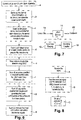
Figure 6 , the main operating steps or stages in this operation of thenetwork 2 are as follows. - The
central unit 6 collects (step a) channel state information (CSI) from all thebase stations 8, in this example in full version (unquantised CSI, in other words perfect CSI) feedback from user terminals in Time Division Duplex (TDD) mode. In other similar embodiments (not shown), the CSI may be quantised (in other words imperfect) such as Channel Quality Indicator CQI, Precoding Matrix Indicator PMI, Rank Indicator RI, DeModulation Reference Signal DM-RS and User Equipment Reference Signal UE-RS, etc). - From the CSI, the central unit calculates (step b) the optimal power control matrix that minimises self-interference also known as rounding noise, as described in more detail below.
- From the CSIs and the power control matrix, the
central unit 4 generates (step c) a network transfer function B. - A precoding matrix is derived from the network transfer function and is applied to precode (step d) the data streams prior to transmission. Specifically the inverse of B , namely, (B T B)-1 B T is referred to as the precoding matrix, and is used to generated the precoded data stream given by

- The
central unit 4 sends the precoded data streams vℓ to the corresponding base stations ℓ, ℓ ∈ {1,...,L}. Then base stations ℓ encode (step e, combining modulation and coding together) the precoded data streams v ℓ into a Low Density Lattice Code (LDLC) codewords xℓ for transmission. The code words are transmitted (step f). - Each user terminal UE i receives the signals transmitted by the base stations and rounds (step g) the channels into integers b i , where the integer coefficient b i is considered as the row vector from B .
- Then the user terminal decodes (step h) the linear combination of all codewords , i.e.b i V, from
base stations 8 using its respectiveSISO LDLC decoder 16. - The decoded linear combination b i V directly equals to the UE i's desired data stream w i (as can be seen from the precoding (step d) above).
- The operation of the user terminal is also shown in
Figure 8 , where Step A is the receiving and rounding, step B is the decoding and Step C is the user data recovery. - These stages shown in
Figure 6 and 8 are described in more detail as follows. - Suppose there are L base stations (BS) serving K user terminals (UEs). The superimposed signal at the UE i is theoretically of the following form

- Treating the network as a distributed MIMO system, the received signals at all UEs follow


- The channel coefficients are rounded in order to form the integer combination of lattice codewords. Accordingly, the above-mentioned theoretical signal is expanded as


- The central unit determines the optimal power control matrix P and the precoding function is based on the determined power P and channels as described below.
- The variance of the effective noise is given by

- Based on the above rounding operation, we expand the theoretical signals as

- The variance of the effective noise Z is calculated as

- As the total power is constrained, the power control algorithm aims at minimizing the variance of the effective noise, given by


- Based on the equation


- This optimal network transfer function B is a matrix that asymptotically maximises the downlink sum capacity.
- This network transfer function is used in the precoding procedure as described next.
- Before transmitting signals over backhaul link to the base stations, the central unit precodes the desired data for the user terminals (UEs), denoted by [w 1,...,w K ] T as follows

- Individual dimensions of each codeword are then mapped to distinct OFDM subcarriers or single antenna element of MIMO system. The encoding procedure is shown in
Figure 7 . - As shown in
Figure 7 , in eachLDLC encoder 14, Hypercube shaping 16 and Low Density Lattice Code (LDLC) encoding 18 are undertaken of input user data 20 so as to provide thecodeword 22. - Let Fℓ : Z n → R n denote the modulation function used, which includes both the hypercube shaping and LDLC encoding as described below. At each
base station 8, the resultinglattice codeword 22 is generated by x ℓ = F ℓ (v ℓ), ℓ ∈ {1,...,L}. - This is explained in more detail as follows.
- An n -dimensional lattice, denoted by A, is a set of points in the n -dimensional real space, denoted by R" , such that if x, y ∈ Λ, then x + y ∈ Λ ; and if x ∈ A, then -x ∈ Λ. A lattice can always be written in terms of a lattice generator matrix G ∈ R n×n Λ = {x = Gv : v ∈ Z n }, where Z n denotes the n -dimensional integer vector space.
- The low-density lattice code (LDLC) is constructed by extending the parity check and syndrome matrices of the well-known low-density parity check codes (LDPC) over finite field to real or complex field. An n dimensional LDLC is an n-dimensional lattice code with a non-singular generator matrix G satisfying det |G| = 1, whose parity check matrix W = G -1 is sparse.
- The row or column degree of w is defined as the number of nonzero elements in row or column, respectively. A n -dimensional LDLC is regular if all the row degrees and column degrees of the parity check matrix are equal to a common degree d. A n -dimensional regular LDLC with degree d is called "Latin square LDLC" if every row and column of the parity check matrix has the same nonzero values, except for a possible change of order and random signs. The sorted sequence of these d values will be referred to as the generating sequence of the Latin square LDLC.
- Here is a simple example of the parity check matrix of a real LDLC with dimension n = 6,
row degree 4, column degree 3 and generating sequence {1,0.8,0.7,0.5},
- In practice, it is necessary to apply a shaping algorithm such that the LDLC codewords meet transmission power constraints. In this example, each base station adopts hypercube shaping. Hypercube shaping is based on a lower triangular parity-check matrix w, in which the integer information vector v ℓ is transferred to another integer vector v' ℓ such that x'ℓ = Gv' ℓ satisfies the power constraint.
- The hypercube shaping operation is given by


- One infers x' ℓ = x ℓ mod Λ from v' ℓ = v ℓ mod M due to the linearity of LDLC.
- Each base station transmits its signal with the appropriate power determined by central unit. More specifically, at each
base station 8 the resultinglattice code word 22 is transmitted at a power previously determined in the power control matrix P described above. - As such, the actual signals received by a user terminal after scaling may be represented as


SISO LDLC decoder 24 in theuser equipment 4. - At the respective user terminal UE i, in order to decode the desired integer combination t i , the
decoder 24 has to follow the following distribution


- Expanding t i as follows

SISO LDLC decoder 24, given by
- The
decoder 24 iteratively estimates
- Let ti [1],...,ti [j],...,ti [n] and ci [1],...,ci [j],...,ci [n] denote the variable nodes and check nodes, respectively. Each variable node corresponds to a single element of the lattice codeword. Each check node corresponds to a check equation, in other words a row of matrix W.
- The
SISO decoder 24 for LDLC lattice combination t i may be summarized as the following algorithm: - Initialization: the variable node ti [j] sends the message
- Basic iteration of check node message: each check node shares a different message with the neighbouring variable nodes. Suppose there are m (equals the row degree of w) variable nodes connected to the check node ci [j], denoted by ti,υ [j],υ ∈ {1,...,m}. We have an appropriate check equation

- 1) Convolution step: all messages excluding ƒυ (ti ) are convolved, where


- 2) Stretching step: p̃τ (ti ) is stretched by -ητ to pτ (ti ) = p̃τ (-ητti ).
- 3) Periodic extension step: pτ (ti ) is extended to a periodic function with
period 
- Basic iteration of variable node message: each variable node sends a message to the neighbouring check node.
- Suppose there are e (equals to the column degree of w) check nodes connected to the variable node ti [j], which are denoted by ci,λ [j],λ∈{1,...,e}. The message sent back to the variable node ti [j] by the check node ci,λ [j] in the previous half-iteration is denoted by Pλ (ti ). The calculation of the message sent from the variable node ti [j] to the check node ci,τ [j] follows the two basic steps:
- 1) The product step

- 2) The normalization step
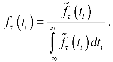
- Repetition: The basis iteration is repeated until the iteration threshold is achieved.
- Final Decision: To extract the desired integer combination of BSs' message, r i , the final PDF of the codeword elements ti [1],...,ti [j],...,ti [n] is estimated in the final iteration without excluding any check node message in the product step, given by

- Then, the estimated codeword element is obtained from t̂i = arg max ƒ̃ j,final(ti ). At last, the desired r i is calculated as

- Recalling that the equalities


- Accordingly, each user terminal directly extracts its desired message

- This approach significantly reduces computational complexity at user terminals since the linear complexity of a
SISO decoder 24 does not grow with the numbers of user terminals and the coefficients are determined by thecentral unit 6 rather than theuser terminals 4. - The present invention may be embodied in other specific forms without departing from its essential characteristics. The described embodiments are to be considered in all respects only as illustrative and not restrictive. The scope of the invention is, therefore, indicated by the appended claims rather than by the foregoing description. All changes that come within the meaning and range of equivalency of the claims are to be embraced within their scope.
- A person skilled in the art would readily recognize that steps of various above-described methods can be performed by programmed computers. Some embodiments relate to program storage devices, e.g., digital data storage media, which are machine or computer readable and encode machine-executable or computer-executable programs of instructions, wherein said instructions perform some or all of the steps of said above-described methods. The program storage devices may be, e.g., digital memories, magnetic storage media such as a magnetic disks and magnetic tapes, hard drives, or optically readable digital data storage media. Some embodiments involve computers programmed to perform said steps of the above-described methods.


Claims (14)
- A method of multipoint joint transmission downlink of user data from a plurality of base stations for wireless communications to at least one user terminal, in which the user data at each base station are encoded as Low Density Lattice, LDL, codewords and the codewords are transmitted over air.
- A method according to claim 1, in which there are multiple user terminals and the method is a distributed Multiple-Input Multiple-Output, MIMO, method.
- A method according to claim 1 or clam 2, in which a controller precodes the user data and provides the precoded user data to the base stations for transmission.
- A method according to claim 3, in which the precoded user data is provided to the base stations over backhaul links.
- A method according to claim 3 or claim 4, in which the controller controls the transmission powers of the base stations.
- A method according to any of claims 3 to 5, in which the controller receives channel state information from the base stations and determines a power control matrix.
- A method according to claim 6, in which the controller derives a network transfer function from the power control matrix, and uses the network transfer function in precoding user data for transmission.
- A method according to claim 6 or claim 7, in which the controller sends the power control matrix to the base stations for controlling transmission power of signals onto which the user data is modulated.
- A controller for controlling multiple cellular wireless communications base stations for joint transmission downlink of user data, the controller being configured to:receive channel state information from the base stations and determine a power control matrix,derive a network transfer function from the power control matrix,use the network transfer function in precoding user data for transmission,send the user data to the respective base stations for transmission downlink over air,send the power control matrix to the base stations for controlling transmission power of signals onto which the user data is modulated.
- A transmitting network comprising the controller according to claim 9 and the multiple base stations which are connected to the controller, in which the base stations encode their respective user data onto Low Density Lattice code words and the code words are modulated onto carrier signals for transmission.
- A transmitting network according to claim 10, in which the base stations transmit at powers specified in the power control matrix.
- A user terminal configured to receive user data from multiple transmitters, the user data from each transmitter having being encoded as a Low Density Lattice codeword, and the multiple Low Density Lattice codewords having been transmitted so as to be received as a combined signal at the receiver, the receiver comprising:a receiving stage configured to receive the signal;an iterative processing stage configured to provide a linear combination, the iterative processing stage comprising:a processor configured to calculate coefficients of the linear combination of the codewords from the multiple transmitters,a processor configured to calculate a scaling factor to be applied to the signal based on the coefficients,a processor configured to apply the scaling factor to the signal to provide a linear combination of the codewords, anda decoder configured to estimate the user data based on channel state information and the linear combination of the codewords.
- A user terminal according to claim 12, in which the decoder is a Single-Input Single Output, SISO decoder.
- A user terminal according to claim 12 or 13, in which the channel coefficients of the received signal are rounded into integer values by the iterative processing stage.
Priority Applications (2)
| Application Number | Priority Date | Filing Date | Title |
|---|---|---|---|
| EP15306783.0A EP3168998A1 (en) | 2015-11-10 | 2015-11-10 | A controller, a transmitting network, a user terminal, and a method of multipoint joint transmission downlink |
| PCT/EP2016/077134 WO2017081075A1 (en) | 2015-11-10 | 2016-11-09 | A controller, a transmitting network, a user terminal, and a method of multipoint joint transmission downlink |
Applications Claiming Priority (1)
| Application Number | Priority Date | Filing Date | Title |
|---|---|---|---|
| EP15306783.0A EP3168998A1 (en) | 2015-11-10 | 2015-11-10 | A controller, a transmitting network, a user terminal, and a method of multipoint joint transmission downlink |
Publications (1)
| Publication Number | Publication Date |
|---|---|
| EP3168998A1 true EP3168998A1 (en) | 2017-05-17 |
Family
ID=54541003
Family Applications (1)
| Application Number | Title | Priority Date | Filing Date |
|---|---|---|---|
| EP15306783.0A Withdrawn EP3168998A1 (en) | 2015-11-10 | 2015-11-10 | A controller, a transmitting network, a user terminal, and a method of multipoint joint transmission downlink |
Country Status (2)
| Country | Link |
|---|---|
| EP (1) | EP3168998A1 (en) |
| WO (1) | WO2017081075A1 (en) |
Cited By (1)
| Publication number | Priority date | Publication date | Assignee | Title |
|---|---|---|---|---|
| CN108365919A (en) * | 2018-02-05 | 2018-08-03 | 西安电子科技大学 | Based on LDLC relay transmissions and corresponding combined decoding method |
Families Citing this family (1)
| Publication number | Priority date | Publication date | Assignee | Title |
|---|---|---|---|---|
| CN116614340B (en) * | 2023-06-30 | 2025-09-12 | 西安邮电大学 | A SCMA codebook design method based on joint bounds |
Citations (1)
| Publication number | Priority date | Publication date | Assignee | Title |
|---|---|---|---|---|
| WO2015081277A1 (en) * | 2013-11-27 | 2015-06-04 | Futurewei Technologies, Inc. | Method and apparatus for downlink transmission in a cloud radio access network |
-
2015
- 2015-11-10 EP EP15306783.0A patent/EP3168998A1/en not_active Withdrawn
-
2016
- 2016-11-09 WO PCT/EP2016/077134 patent/WO2017081075A1/en not_active Ceased
Patent Citations (1)
| Publication number | Priority date | Publication date | Assignee | Title |
|---|---|---|---|---|
| WO2015081277A1 (en) * | 2013-11-27 | 2015-06-04 | Futurewei Technologies, Inc. | Method and apparatus for downlink transmission in a cloud radio access network |
Non-Patent Citations (10)
| Title |
|---|
| CHEN BIN ET AL: "Cooperative relaying with low-density lattice coding and joint iterative decoding", 2014 8TH INTERNATIONAL SYMPOSIUM ON TURBO CODES AND ITERATIVE INFORMATION PROCESSING (ISTC), IEEE, 18 August 2014 (2014-08-18), pages 254 - 258, XP032682442, DOI: 10.1109/ISTC.2014.6955124 * |
| E. BJ6MSON; R. ZAKHOUR; D. GESBERT; B. OTTERSTEN: "Cooperative multicell precoding: Rate region characterization and distributed strategies with instantaneous and statistical CSI", IEEE TRANS. SIGNAL PROCESS., vol. 58, no. 8, August 2010 (2010-08-01), pages 4298 - 4310, XP011308848 |
| HONG SONG-NAM ET AL: "Compute-and-Forward Strategies for Cooperative Distributed Antenna Systems", IEEE TRANSACTIONS ON INFORMATION THEORY, IEEE PRESS, USA, vol. 59, no. 9, 1 September 2013 (2013-09-01), pages 5227 - 5243, XP011526399, ISSN: 0018-9448, [retrieved on 20130814], DOI: 10.1109/TIT.2013.2265695 * |
| JINFENG DU ET AL: "Cooperative strategies for relay-aided multi-cell wireless networks with backhaul", INFORMATION THEORY WORKSHOP (ITW), 2010 IEEE, IEEE, PISCATAWAY, NJ, USA, 30 August 2010 (2010-08-30), pages 1 - 5, XP031769069, ISBN: 978-1-4244-8262-7 * |
| N. SOMMER; M. FEDER; O. SHALVI: "Low-density lattice codes", INFORMATION THEORY, IEEE TRANSACTIONS, vol. 54, no. 4, April 2008 (2008-04-01), pages 1561 - 1585 |
| S. LIU; J. WU: "A 25 Gbit/s(/km2) urban wireless network beyond IMT Advanced", IEEE COMMUNICATIONS MAGAZINE, vol. 49, no. 2, February 2011 (2011-02-01), pages 122 - 129 |
| SOMMER N ET AL: "Shaping methods for low-density lattice codes", INFORMATION THEORY WORKSHOP, 2009. ITW 2009. IEEE, IEEE, PISCATAWAY, NJ, USA, 11 October 2009 (2009-10-11), pages 238 - 242, XP031579039, ISBN: 978-1-4244-4982-8 * |
| U. VILAIPOMSAWAI ET AL.: "Cornell University Library CoRR", 2015, article "SCMA for Open-Loop Joint Transmission CoMP" |
| U. VILAIPORNSAWAI ET AL.: "Cornell University Library CoRR abstract /1504.01747", 2015, article "SCMA for Open-Loop Joint Transmission CoMP" |
| VILAIPORNSAWAI USA ET AL: "SCMA for Open-Loop Joint Transmission CoMP", 2015 IEEE 82ND VEHICULAR TECHNOLOGY CONFERENCE (VTC2015-FALL), IEEE, 6 September 2015 (2015-09-06), pages 1 - 5, XP032857285, DOI: 10.1109/VTCFALL.2015.7391126 * |
Cited By (2)
| Publication number | Priority date | Publication date | Assignee | Title |
|---|---|---|---|---|
| CN108365919A (en) * | 2018-02-05 | 2018-08-03 | 西安电子科技大学 | Based on LDLC relay transmissions and corresponding combined decoding method |
| CN108365919B (en) * | 2018-02-05 | 2020-04-07 | 西安电子科技大学 | LDLC (Low Density parity check) based relay transmission and corresponding joint decoding method |
Also Published As
| Publication number | Publication date |
|---|---|
| WO2017081075A1 (en) | 2017-05-18 |
Similar Documents
| Publication | Publication Date | Title |
|---|---|---|
| Yu et al. | An efficient rate-splitting multiple access scheme for the downlink of C-RAN systems | |
| CN110612671B (en) | Non-orthogonal multiple access communication method and system | |
| CN102308508B (en) | Adaptive precoding codebooks for wireless communications | |
| EP2337236B1 (en) | Method and transmitter for transmitting spatially precoding data | |
| KR102201073B1 (en) | Receiver, a plurality of transmitters, a method of receiving user data from a plurality of transmitters, and a method of transmitting user data | |
| CN107710838A (en) | A kind of method for carrying out power distribution and pre-coding matrix calculating in a wireless communication system | |
| Karmakar et al. | The diversity-multiplexing tradeoff of the dynamic decode-and-forward protocol on a MIMO half-duplex relay channel | |
| JP2018529285A5 (en) | ||
| Liu et al. | Interference alignment transceiver design for MIMO interference broadcast channels | |
| Oechtering et al. | Optimal transmit strategies in multi-antenna bidirectional relaying | |
| CN117240669A (en) | Soft decision detection method and system for multi-stream data integer combination | |
| EP3168998A1 (en) | A controller, a transmitting network, a user terminal, and a method of multipoint joint transmission downlink | |
| Hasabelnaby et al. | Multi-pair computation for two-way intra cloud radio-access network communications | |
| Hyadi et al. | Secure multiple-antenna block-fading wiretap channels with limited CSI feedback | |
| Gouissem et al. | Multiple relay selection and beamforming in dual-hop amplify-and-forward relay networks | |
| Maleki et al. | Distributed robust beamforming in multi-user relay network | |
| El Bakoury et al. | Uplink-downlink duality for integer-forcing in cloud radio access networks | |
| Yang et al. | A signal-space aligned network coding approach to distributed MIMO | |
| Hasabelnaby et al. | Multi-pair computation for c-ran with intra-cloud and inter-cloud communications | |
| CN105429685A (en) | Efficient Uplink Transmission in Massive MIMO | |
| Anand et al. | Precoder designs for the relay-aided X channel without source CSI | |
| Sohtsinda et al. | Amplifier-aware content-based precoder design for hierarchical image transmission over a realistic MIMO-OFDM channel | |
| Chan et al. | Reverse signal-aligned network coding in interference channels with limited transmitter cooperation | |
| EP3160054A1 (en) | A wireless communication network having coordinated multiple base stations | |
| WO2018228704A1 (en) | A network device, a user equipment and a method for wireless data transmission |
Legal Events
| Date | Code | Title | Description |
|---|---|---|---|
| PUAI | Public reference made under article 153(3) epc to a published international application that has entered the european phase |
Free format text: ORIGINAL CODE: 0009012 |
|
| AK | Designated contracting states |
Kind code of ref document: A1 Designated state(s): AL AT BE BG CH CY CZ DE DK EE ES FI FR GB GR HR HU IE IS IT LI LT LU LV MC MK MT NL NO PL PT RO RS SE SI SK SM TR |
|
| AX | Request for extension of the european patent |
Extension state: BA ME |
|
| 17P | Request for examination filed |
Effective date: 20171117 |
|
| RBV | Designated contracting states (corrected) |
Designated state(s): AL AT BE BG CH CY CZ DE DK EE ES FI FR GB GR HR HU IE IS IT LI LT LU LV MC MK MT NL NO PL PT RO RS SE SI SK SM TR |
|
| RAP1 | Party data changed (applicant data changed or rights of an application transferred) |
Owner name: ALCATEL LUCENT |
|
| 17Q | First examination report despatched |
Effective date: 20181015 |
|
| GRAP | Despatch of communication of intention to grant a patent |
Free format text: ORIGINAL CODE: EPIDOSNIGR1 |
|
| RIC1 | Information provided on ipc code assigned before grant |
Ipc: H04B 7/024 20170101AFI20190521BHEP Ipc: H04L 1/00 20060101ALI20190521BHEP Ipc: H04B 7/0452 20170101ALI20190521BHEP Ipc: H04W 52/14 20090101ALI20190521BHEP Ipc: H04L 1/06 20060101ALI20190521BHEP |
|
| INTG | Intention to grant announced |
Effective date: 20190619 |
|
| STAA | Information on the status of an ep patent application or granted ep patent |
Free format text: STATUS: THE APPLICATION IS DEEMED TO BE WITHDRAWN |
|
| 18D | Application deemed to be withdrawn |
Effective date: 20191030 |