EP3168688A1 - Fixing device and image forming apparatus - Google Patents
Fixing device and image forming apparatus Download PDFInfo
- Publication number
- EP3168688A1 EP3168688A1 EP16187745.1A EP16187745A EP3168688A1 EP 3168688 A1 EP3168688 A1 EP 3168688A1 EP 16187745 A EP16187745 A EP 16187745A EP 3168688 A1 EP3168688 A1 EP 3168688A1
- Authority
- EP
- European Patent Office
- Prior art keywords
- halogen lamp
- lamp heater
- temperature
- output duty
- reference voltage
- Prior art date
- Legal status (The legal status is an assumption and is not a legal conclusion. Google has not performed a legal analysis and makes no representation as to the accuracy of the status listed.)
- Granted
Links
Images


Classifications
-
- G—PHYSICS
- G03—PHOTOGRAPHY; CINEMATOGRAPHY; ANALOGOUS TECHNIQUES USING WAVES OTHER THAN OPTICAL WAVES; ELECTROGRAPHY; HOLOGRAPHY
- G03G—ELECTROGRAPHY; ELECTROPHOTOGRAPHY; MAGNETOGRAPHY
- G03G15/00—Apparatus for electrographic processes using a charge pattern
- G03G15/20—Apparatus for electrographic processes using a charge pattern for fixing, e.g. by using heat
- G03G15/2003—Apparatus for electrographic processes using a charge pattern for fixing, e.g. by using heat using heat
- G03G15/2014—Apparatus for electrographic processes using a charge pattern for fixing, e.g. by using heat using heat using contact heat
- G03G15/2039—Apparatus for electrographic processes using a charge pattern for fixing, e.g. by using heat using heat using contact heat with means for controlling the fixing temperature
-
- G—PHYSICS
- G03—PHOTOGRAPHY; CINEMATOGRAPHY; ANALOGOUS TECHNIQUES USING WAVES OTHER THAN OPTICAL WAVES; ELECTROGRAPHY; HOLOGRAPHY
- G03G—ELECTROGRAPHY; ELECTROPHOTOGRAPHY; MAGNETOGRAPHY
- G03G15/00—Apparatus for electrographic processes using a charge pattern
- G03G15/20—Apparatus for electrographic processes using a charge pattern for fixing, e.g. by using heat
- G03G15/2003—Apparatus for electrographic processes using a charge pattern for fixing, e.g. by using heat using heat
- G03G15/2007—Apparatus for electrographic processes using a charge pattern for fixing, e.g. by using heat using heat using radiant heat, e.g. infrared lamps, microwave heaters
-
- G—PHYSICS
- G03—PHOTOGRAPHY; CINEMATOGRAPHY; ANALOGOUS TECHNIQUES USING WAVES OTHER THAN OPTICAL WAVES; ELECTROGRAPHY; HOLOGRAPHY
- G03G—ELECTROGRAPHY; ELECTROPHOTOGRAPHY; MAGNETOGRAPHY
- G03G15/00—Apparatus for electrographic processes using a charge pattern
- G03G15/20—Apparatus for electrographic processes using a charge pattern for fixing, e.g. by using heat
- G03G15/2003—Apparatus for electrographic processes using a charge pattern for fixing, e.g. by using heat using heat
- G03G15/2014—Apparatus for electrographic processes using a charge pattern for fixing, e.g. by using heat using heat using contact heat
- G03G15/2039—Apparatus for electrographic processes using a charge pattern for fixing, e.g. by using heat using heat using contact heat with means for controlling the fixing temperature
- G03G15/2042—Apparatus for electrographic processes using a charge pattern for fixing, e.g. by using heat using heat using contact heat with means for controlling the fixing temperature specially for the axial heat partition
Definitions
- the present invention relates to a fixing device and an image forming apparatus.
- Duty control depending on a time ratio the following control operations have been suggested: a control operation in which a halogen lamp heater is switched on in accordance with the color temperature of the halogen lamp heater, except for the time Duty during which a chemical attack is likely to occur (see JP 2012-53148 A , for example); and a control operation in which a check is made to determine whether a chemical attack has occurred by calculating deviation of the halogen gas density in the tube from the color temperature, and a halogen lamp heater is switched on to cancel the deviation of the halogen gas density (see JP 2012-63644 , for example).
- Duty control depending on a time ratio involves minute segmentation of alternating current. As a result, terminal noise or harmonic noise is generated, and the antinoise circuit and components become complicated.
- an object of the present invention is to provide a fixing device that can appropriately prevent chemical attacks when performing half-wave control on halogen lamp heaters, and an image forming apparatus that includes the fixing device.
- a fixing device reflecting one aspect of the present invention comprises:
- a fixing device reflecting one aspect of the present invention comprises:
- Fig. 1 is a diagram schematically showing the configuration of an image forming apparatus 1 that is an embodiment of the present invention.
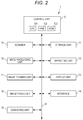
- Fig. 2 is a block diagram showing the principal functional configuration of the image forming apparatus 1.
- the image forming apparatus 1 includes a control unit 10 that includes a central processing unit (CPU) 101, a random access memory (RAM) 102, and a read only memory (ROM) 103, a storage unit 11, an operating unit 12, a display unit 13, an interface 14, a scanner 15, an image processing unit 16, an image forming unit 17, an image fixing unit 18, and a conveying unit 19.
- the control unit 10 is connected to the storage unit 11, the operating unit 12, the display unit 13, the interface 14, the scanner 15, the image processing unit 16, the image forming unit 17, the image fixing unit 18, and the conveying unit 19.
- the CPU 101 reads and executes control programs stored in the ROM 103 or the storage unit 11, and performs various calculation processes.
- the RAM 102 provides a work memory space for the CPU 101, and temporarily stores data.
- the ROM 103 stores various control programs to be executed by the CPU 101, setting data, and the like.
- a rewritable nonvolatile memory such as an electrically erasable programmable read only memory (EEPROM) or a flash memory, may be used.
- EEPROM electrically erasable programmable read only memory
- the control unit 10 including the CPU 101, the RAM 102, and the ROM 103 collectively controls the respective components of the image forming apparatus 1 in accordance with the above various control programs.
- the control unit 10 causes the image processing unit 16 to perform predetermined image processing on image data and store the image data into the storage unit 11.
- the control unit 10 also causes the conveying unit 19 to convey a paper sheet, and causes the image forming unit 17 to form an image on the paper sheet in accordance with the image data stored in the storage unit 11.
- the storage unit 11 is formed with a dynamic random access memory (DRAM) or the like, and stores image data obtained with the scanner 15, image data input from the outside via the interface 14, and the like. Such image data and the like may be stored in the RAM 102.
- DRAM dynamic random access memory
- the operating unit 12 includes input devices, such as operation keys and a touch panel placed on the screen of the display unit 13.
- the operating unit 12 converts an operation that is input through these input devices into an operation signal, and outputs the operation signal to the control unit 10.
- the display unit 13 includes a display device, such as a liquid crystal display (LCD), and displays an operation screen or the like that shows the state of the image forming apparatus 1 or the contents of the operation input through the touch panel.
- a display device such as a liquid crystal display (LCD)
- LCD liquid crystal display
- the interface 14 is a means to perform data transmission/reception with an external computer, another image forming apparatus, or the like, and is formed with a serial interface of one of various kinds, for example.
- the scanner 15 reads an image formed on a paper sheet, generates image data including single-color data of each of the color components R (red), G (green), and B (blue), and stores the image data into the storage unit 11.
- the image processing unit 16 includes a rasterizing unit, a color converting unit, a tone correcting unit, and a halftone processing unit, for example.
- the image processing unit 16 performs various kinds of image processing on the image data stored in the storage unit 11, and stores the processed image data into the storage unit 11.
- the image forming unit 17 forms an image on a paper sheet in accordance with the image data stored in the storage unit 11.
- the image forming unit 17 includes four sets of an exposing unit 171, a photosensitive member 172, and a developing unit 173. These four sets correspond to the respective color components C (cyan), M (magenta), Y (yellow), and K (black).
- the image forming unit 17 also includes a transfer member 174 and secondary transfer rollers 175.
- Each exposing unit 171 includes a laser diode (LD) as a light emitting element.
- the exposing unit 171 drives the LD in accordance with the image data, irradiates and exposes the charged photosensitive member 172 with laser light, and forms an electrostatic latent image on the photosensitive member 172.
- the developing unit 173 supplies toner (color material) of a predetermined color (one of C, M, Y, and K) onto the charged photosensitive member 172 with a charged developing roller, and develops the electrostatic latent image formed on the photosensitive member 172.
- the transfer member 174 is an endless belt wound around transfer member conveying rollers, and rotates with the respective transfer member conveying rollers.
- the secondary transfer rollers 175 transfer the color image on the transfer member 174 onto a paper sheet supplied from a paper feed tray 22 or a sheet feeder provided outside. Specifically, when a predetermined transfer voltage is applied to the secondary transfer rollers 175 having a paper sheet and the transfer member 174 nipped in between, the toner forming the color image on the transfer member 174 is drawn toward the paper sheet, and thus, is transferred to the paper sheet.
- the image fixing unit 18 performs a fixing process of fixing the toner to the paper sheet by heating and pressing the paper sheet having the toner transferred thereto.
- Fig. 3 is a schematic diagram showing the structure of the image fixing unit 18.
- the image fixing unit 18 includes a fixing roller (the fixing member) 183, a pressure roller (the pressure member) 184, and a temperature detecting unit 185.
- the image fixing unit 18 and the control unit 10 constitute a fixing device.
- the fixing roller 183 includes halogen lamp heaters 186 through 188 extending in the rotational axis thereof.
- the halogen lamp heaters 186 through 188 generate heat when energized under the control of the control unit 10.
- the fixing roller 183 is driven by a rotary drive means (not shown), such as a motor, under the control of the control unit 10.
- the temperature detecting unit 185 that detects the temperature of the fixing roller 183 is also attached to the fixing roller 183. Only one temperature detecting unit 185 may be provided, or more than one temperature detecting unit 185 may be provided, as long as the temperature of the fixing roller 183 can be detected.
- Fig. 4 is a schematic diagram showing the internal structure of the fixing roller 183.
- the halogen lamp heaters 186 through 188 are formed with tungsten filaments 186b through 188b in cylindrical portions 186a through 188a, and halogen gases of predetermined densities are contained in the respective cylindrical portions 186a through 188a.
- reference voltages of the respective halogen lamp heaters 186 through 188 are set.
- a reference voltage in the present invention is a voltage to be applied to a halogen lamp heater so that a halogen cycle can be performed in the smoothest manner without any chemical attack or the like.
- a reference voltage has a value that is set for each halogen lamp heater in accordance with the density of the contained halogen gas.
- the filament 186b of the halogen lamp heater 186 is designed to heat only the central portion of the fixing roller 183 in its axial direction
- the filament 187b of the halogen lamp heater 187 is designed to heat the entire portion of the fixing roller 183 in its axial direction
- the filament 188b of the halogen lamp heater 188 is designed to heat only the end portions of the fixing roller 183 in its axial direction.
- the pressure roller 184 may rotate when being driven by a rotary drive means (not shown), such as a motor, under the control of the control unit 10.
- the fixing roller 183 and the pressure roller 184 heat and press a paper sheet P while nipping the paper sheet P with the fixing nip and conveying the paper sheet P in a conveyance direction R indicated by an arrow in Fig. 3 .
- the fixing roller 183 and the pressure roller 184 melt and fix the toner on the paper sheet P.
- the temperature of the fixing roller 183 is in the range of 180 to 200 degrees centigrade, for example. Therefore, the halogen lamp heaters 186 through 188 heat the fixing roller 183 so that the temperature of the fixing roller 183 becomes a temperature within this range.
- the conveying unit 19 includes sheet conveying rollers that convey a paper sheet by rotating while nipping the paper sheet.
- the conveying unit 19 conveys the paper sheet through a predetermined conveyance path.
- the conveying unit 19 includes a reversing mechanism 191 that reverses a paper sheet on which a fixing process has been performed by the image fixing unit 18, and then conveys the paper sheet to the secondary transfer rollers 175.
- the image forming apparatus 1 in a case where images are to be formed on both surfaces of a paper sheet, the paper sheet is reversed by the reversing mechanism 191. After the images are formed on both surfaces, the paper sheet is discharged onto a paper receiving tray 23. In a case where an image is to be formed on one surface of a paper sheet, the paper sheet is not reversed by the reversing mechanism 191. After the image is formed on the one surface, the paper sheet is discharged onto the paper receiving tray 23.
- the control unit 10 performs half-wave control on the halogen lamp heater 186 by calculating an output Duty in accordance with a temperature detected by the temperature detecting unit 185 and performing energization or de-energization for each half-wave of an AC waveform in accordance with the output Duty, and performs switch on/off control on the halogen lamp heaters 187 and 188. That is, the halogen lamp heater 186 serves as a first halogen lamp heater, and the halogen lamp heaters 187 and 188 serve as second halogen lamp heaters.
- the control unit 10 controls the voltage to be applied to the halogen lamp heater 186 by performing half-wave control to control energization for each half-wave of the voltage waveform of an AC power supply (not shown).
- a half-wave means a waveform that has a length equivalent to half a cycle of the voltage waveform of the AC power supply, and is segmented at 0 degrees in phase and at 180 degrees in phase.
- reference voltages are set in the halogen lamp heaters 186 through 188 in accordance with the densities of the contained halogen gases. If an effective voltage becomes lower than the corresponding reference voltage, a chemical attack occurs. Therefore, in a conventional halogen lamp heater, the density of the halogen gas is set so that the reference voltage has the same value as the rated voltage. In the halogen lamp heaters 187 and 188 on which the control unit 10 performs switch on/off control, the reference voltage is set at the same value as the rated voltage.
- the density of the halogen gas is set at a low value so that the reference voltage is set at a lower value than the rated voltage. That is, the reference voltage of the halogen lamp heater 186 is set at a lower value than the reference voltage of the halogen lamp heaters 187 and 188.
- the halogen lamp heater 186 is designed in this manner, half-wave control is performed so that the effective voltage can be prevented from becoming lower than the reference voltage even if the effective voltage becomes lower than the rated voltage. Thus, chemical attacks can be prevented.
- Table 1 shows an example of the reference voltages of the halogen lamp heaters 186 through 188 and the densities of the halogen gases.
- Halogen lamp heater Type Control method Rated voltage [V] Reference voltage [V] Halogen gas density [mass%] Halogen lamp heater 186 Central light distribution Half-wave control 200 80-100 40-50 Halogen lamp heater 187 Total light distribution On/off control 200 200 100 Halogen lamp heater 188 End light distribution On/off control 200 200 100
- the reference voltage of the halogen lamp heater 186 is set at a value of 80 to 100 V.
- a blackening phenomenon is a phenomenon in which the tungsten gasified from the filament is deposited on the inner surface of the cylindrical portion without binding to the halogen gas in a case where the amount of the contained halogen gas is small.
- the control unit 10 preferably does not output an output Duty equivalent to a voltage that is not lower than 80 V but is lower than 100 V. Not outputting an output Duty equivalent to a voltage that is not lower than 80 V but is lower than 100 V, the control unit 10 outputs an output Duty equivalent to a voltage of 100 V, which is the reference voltage, or sets the output Duty at 0 or outputs an output Duty not to apply any voltage, so that the temperature of the fixing roller 183 approaches a target temperature. Which one of these outputs Duty should be output may be determined in accordance with the transition of the temperature of the fixing roller 183, for example.
- an output Duty not to apply any voltage is output in a case where the transition of temperature of the fixing roller 183 shows a tendency to rise, and an output Duty equivalent to a voltage of 100 V is output in a case where the temperature transition shows a tendency to drop.
- the control unit 10 calculates the output Duty from the temperature of the fixing roller 183 detected by the temperature detecting unit 185 and a predetermined target temperature. The control unit 10 then calculates an effective voltage from the calculated output Duty and the rated voltage of the halogen lamp heater 186. In a case where the calculated effective voltage is higher than the reference voltage of the halogen lamp heater 186, the control unit 10 performs half-wave control with the calculated output Duty. In a case where the calculated effective voltage is lower than the reference voltage of the halogen lamp heater 186, the control unit 10 determines whether a temperature change detected by the temperature detecting unit 185 shows a tendency to rise or whether the temperature change shows a tendency to drop.
- control unit 10 sets the output duty at 0. In a case where the temperature change shows a tendency to drop, the control unit 10 performs half-wave control with the output Duty equivalent to the reference voltage of the halogen lamp heater 186.
- Fig. 5 an example of a temperature control process to be performed on the halogen lamp heater 186 by the control unit 10 is described in detail.
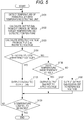
- Fig. 5 is a flowchart showing the example of a temperature control process to be performed on the halogen lamp heater 186.
- the control unit 10 performs the conventional switch on/off control on the halogen lamp heaters 187 and 188, and therefore, explanation thereof is not made herein.
- control unit 10 detects the temperature of the fixing roller 183 with the temperature detecting unit 185 (step S101). It should be noted that the control unit 10 detects the temperature of the fixing roller 183 with the temperature detecting unit 185 in real time, and continues the temperature detection in the respective procedures after step S101.
- control unit 10 calculates an output Duty from a predetermined target temperature and the temperature detected through the procedure in step S101 (step S102).
- the control unit 10 then calculates an effective voltage from the output Duty calculated in step S102 and the rated voltage of the halogen lamp heater 186 (step S103).
- control unit 10 determines whether the effective voltage calculated in step S103 is equal to or higher than the reference voltage of the halogen lamp heater 186 (step S104).
- the reference voltage of the halogen lamp heater 186 has been set beforehand at the time of the manufacturing of the halogen lamp heaters, and is stored in the storage unit 11, the RAM 102, or the like.
- step S104 If the effective voltage is determined to be equal to or higher than the reference voltage of the halogen lamp heater 186 (YES in step S104), the control unit 10 outputs the output Duty calculated in step S102 (step S105). For example, in a case where the reference voltage of the halogen lamp heater 186 is 80 V, and the calculated effective voltage is 100 V, it is safe to assume that no chemical attacks will occur. Therefore, the control unit 10 outputs the calculated output Duty, to apply a voltage of 100 V to the halogen lamp heater 186.
- the control unit 10 determines whether the temperature of the fixing roller 183 shows a tendency to rise (step S106). Specifically, in accordance with the transition of the temperature of the fixing roller 183 being detected by the temperature detecting unit 185 in real time, the control unit 10 determines whether the temperature of the fixing roller 183 shows a tendency to rise or whether the temperature of the fixing roller 183 shows a tendency to drop.
- the control unit 10 sets the output Duty at 0, or outputs such an output Duty as not to apply any voltage to the halogen lamp heater 186 (step S107). Consequently, even if the effective voltage is lower than the reference voltage, the halogen lamp heater 186 is put into an off-state, and chemical attacks can be prevented.
- step S106 If the temperature of the fixing roller 183 is determined to show a tendency to drop (NO in step S106), the control unit 10 outputs the output Duty equivalent to the reference voltage (step S108). Consequently, even if the effective voltage is lower than the reference voltage, a voltage equivalent to the reference voltage can be applied to the halogen lamp heater 186. Thus, chemical attacks can be prevented.
- control unit 10 determines whether to end the temperature control (step S109). Specifically, in a case where an image forming process by the image forming unit 17 has ended, the control unit 10 determines to end the temperature control. In a case where the image forming process has not ended, the control unit 10 determines not to end the temperature control. If the control unit 10 determines not to end the temperature control (NO in step S109), the control unit 10 repeats the procedures in steps S101 through S108. If the control unit 10 determines to end the temperature control (YES in step S109), the control unit 10 ends the temperature control process for the halogen lamp heater 186.
- a fixing device that includes the fixing roller 183, the pressure roller 184 pressed against the fixing roller 183, and the halogen lamp heaters 186 through 188 that heat the fixing roller 183 further includes: the temperature detecting unit 185 that detects the temperature of the fixing roller 183; and the control unit 10 that performs half-wave control on the halogen lamp heater 186 by calculating an output Duty in accordance with the temperature detected by the temperature detecting unit 185 and performing energization or de-energization for each half-wave of an AC waveform in accordance with the output Duty, and performs switch on/off control on the halogen lamp heaters 187 and 188.
- the halogen lamp heaters 186 through 188 have reference voltages that are set in accordance with the densities of the contained halogen gases, and the reference voltages satisfy "the reference voltage of the halogen lamp heater 186 ⁇ the reference voltage of the halogen lamp heaters 187 and 188".
- the reference voltage of the halogen lamp heater 186 on which the half-wave control is performed is set at a low value, so that the effective voltage can be prevented from becoming lower than the reference voltage.
- chemical attacks can be appropriately prevented in a case where half-wave control is performed on a halogen lamp heater.
- control unit 10 calculates the output Duty from the temperature of the fixing roller 183 detected by the temperature detecting unit 185 and the predetermined target temperature. The control unit 10 then calculates an effective voltage from the calculated output Duty and the rated voltage of the halogen lamp heater 186. In a case where the calculated effective voltage is higher than the reference voltage of the halogen lamp heater 186, the control unit 10 performs half-wave control with the calculated output Duty. In a case where the calculated effective voltage is lower than the reference voltage of the halogen lamp heater 186, the control unit 10 determines whether a temperature change detected by the temperature detecting unit 185 shows a tendency to rise or whether the temperature change shows a tendency to drop.
- the control unit 10 sets the output duty at 0. In a case where the temperature change shows a tendency to drop, the control unit 10 performs half-wave control with the output Duty equivalent to the reference voltage of the halogen lamp heater 186. Thus, chemical attacks can be prevented, even if the effective voltage becomes lower than the reference voltage in the halogen lamp heater 186.
- the fixing device includes one halogen lamp heater (the halogen lamp heater 186) that serves as a first halogen lamp heater, and two halogen lamp heaters (the halogen lamp heaters 187 and 188) that serve as second halogen lamp heaters.
- a fixing device may include two or more halogen lamp heaters that serve as first halogen lamp heaters, or may include one halogen lamp heater or three or more halogen lamp heaters that serve as second halogen lamp heaters.
- the image forming apparatus 1 of the first modification has substantially the same configuration as the image forming apparatus 1 of the above described embodiment, but differs in the aspects described below. Specifically, in the image forming apparatus 1 of the first modification, the control unit 10 performs the above described half-wave control on the halogen lamp heaters 186 and 188, and performs the switch on/off control on the halogen lamp heater 187.
- the control unit 10 performs half-wave control on the halogen lamp heater 188 that heats the end portions of the fixing roller 183 in its axial direction and on the halogen lamp heater 186 that heats the central portion of the fixing roller 183 in its axial direction by calculating an output Duty in accordance with a temperature detected by the temperature detecting unit 185 and performing energization or de-energization for each half-wave of an AC waveform in accordance with the output Duty. That is, in the first modification, the halogen lamp heater 186 serves as a central-portion halogen lamp heater, and the halogen lamp heater 188 serves as an end-portion halogen lamp heater. In the first modification, the control unit 10 performs switch on/off control on the halogen lamp heater 187.
- the reference voltage and the rated voltage are set at the same value.
- the density of the halogen gas is set at a low value so that the reference voltage is set at a lower value than the rated voltage.
- the halogen lamp heater 188 that heats the end portions of the fixing roller 183 in its axial direction and the halogen lamp heater 186 that heats the central portion of the fixing roller 183 in its axial direction need to be heated to similar temperatures before a start of image formation.
- the amount of heat for the halogen lamp heater 188 is smaller than that for the halogen lamp heater 186, though it depends on the type and the size of the paper during image formation. In a case where half-wave control is performed on both halogen lamp heaters 186 and 188, the output Duty required by the halogen lamp heater 188 is the smaller.
- the reference voltage of the halogen lamp heater 188 is set at a lower value than the reference voltage of the halogen lamp heater 186, so that the effective voltage can be certainly prevented from becoming lower than the reference voltage in the halogen lamp heater 188, and chemical attacks can be effectively prevented.
- the reference voltages of the halogen lamp heaters 186 through 188 of the first modification and the densities of the halogen gases are set as shown in Table 2.
- Halogen lamp heater Type Control method Rated voltage [V] Reference voltage [V] Halogen gas density [mass%] Halogen lamp heater 186 Central light distribution Half-wave control 200 100 50 Halogen lamp heater 187 Total light distribution On/off control 200 200 100 Halogen lamp heater 188 End light distribution Half-wave control 200 80 40
- control unit 10 of the first modification calculates the output Duty from the temperature of the fixing roller 183 detected by the temperature detecting unit 185 and a predetermined target temperature.
- the control unit 10 then calculates an effective voltage from the calculated output Duty and the rated voltage of the halogen lamp heater 188 or the halogen lamp heater 186. In a case where the calculated effective voltage is higher than the reference voltage of the halogen lamp heater 188 or the halogen lamp heater 186, the control unit 10 performs half-wave control with the calculated output Duty.
- the control unit 10 determines whether a temperature change detected by the temperature detecting unit 185 shows a tendency to rise or whether the temperature change shows a tendency to drop. In a case where the temperature change shows a tendency to rise, the control unit 10 sets the output duty at 0. In a case where the temperature change shows a tendency to drop, the control unit 10 performs half-wave control with the output Duty equivalent to the reference voltage of the halogen lamp heater 188 or the halogen lamp heater 186. Specifically, the control unit 10 performs the temperature control process shown in Fig. 5 , for example, on each of the halogen lamp heaters 186 and 188, as in the above described embodiment.
- a fixing device that includes the fixing roller 183, the pressure roller 184 pressed against the fixing roller 183, and the halogen lamp heaters 186 through 188 that heat the fixing roller 183 further includes: the temperature detecting unit 185 that detects the temperature of the fixing roller 183; and the control unit 10 that performs half-wave control on the halogen lamp heater 188 that heats the end portions of the fixing roller 183 in its axial direction and on the halogen lamp heater 186 that heats the central portion of the fixing roller 183 in its axial direction, by calculating an output Duty in accordance with the temperature detected by the temperature detecting unit 185 and performing energization or de-energization for each half-wave of an AC waveform in accordance with the output Duty.
- the halogen lamp heater 188 and the halogen lamp heater 186 have reference voltages that are set in accordance with the densities of the contained halogen gases, and the reference voltages are lower than the rated voltage and satisfy "the reference voltage of the halogen lamp heater 188 ⁇ the reference voltage of the halogen lamp heater 186".
- the reference voltages of the halogen lamp heaters 186 and 188 on which the half-wave control is performed are set at low values, so that the effective voltage can be prevented from becoming lower than the corresponding reference voltage.
- chemical attacks can be appropriately prevented in a case where half-wave control is performed on halogen lamp heaters.
- the halogen lamp heater 188 has a higher frequency of usage of a low output Duty than the halogen lamp heater 186.
- the reference voltage of the halogen lamp heater 188 is set at a lower value than the reference voltage of the halogen lamp heater 186, so that the effective voltage can be certainly prevented from becoming lower than the reference voltage in the halogen lamp heater 188, and chemical attacks can be effectively prevented.
- control unit 10 calculates the output Duty from the temperature of the fixing roller 183 detected by the temperature detecting unit 185 and the predetermined target temperature. The control unit 10 then calculates an effective voltage from the calculated output Duty and the rated voltage of the halogen lamp heater 188 or the halogen lamp heater 186. In a case where the calculated effective voltage is higher than the reference voltage of the halogen lamp heater 188 or the halogen lamp heater 186, the control unit 10 performs half-wave control with the calculated output Duty.
- the control unit 10 determines whether a temperature change detected by the temperature detecting unit 185 shows a tendency to rise or whether the temperature change shows a tendency to drop. In a case where the temperature change shows a tendency to rise, the control unit 10 sets the output duty at 0. In a case where the temperature change shows a tendency to drop, the control unit 10 performs half-wave control with the output Duty equivalent to the reference voltage of the halogen lamp heater 188 or the halogen lamp heater 186. Thus, chemical attacks can be prevented, even if the effective voltage becomes lower than the reference voltages in the halogen lamp heaters 186 and 188.
- the fixing device includes the halogen lamp heater 187 on which the control unit 10 performs switch on/off control.
- the fixing device may not include the halogen lamp heater 187. That is, the fixing device of the first modification may include only the halogen lamp heaters on which the control unit 10 performs half-wave control.
- the fixing device includes one halogen lamp heater (the halogen lamp heater 186) that serves as a central-portion halogen lamp heater, and one halogen lamp heater (the halogen lamp heater 188) that serves as an end-portion halogen lamp heater.
- a fixing device may include two or more halogen lamp heaters that serve as central-portion halogen lamp heaters, or may include two or more halogen lamp heaters that serve as end-portion halogen lamp heaters.
- the image forming apparatus 1 of the second modification has substantially the same configuration as the image forming apparatus 1 of the above described embodiment, but differs in the aspects described below. Specifically, in the image forming apparatus 1 of the second modification, the control unit 10 performs the above described half-wave control on the halogen lamp heaters 186 and 187, and performs the switch on/off control on the halogen lamp heater 188.
- the control unit 10 performs half-wave control on the halogen lamp heater 186 and the halogen lamp heater 187 that heat overlapping portions of the fixing roller 183 in its axial direction by calculating an output Duty in accordance with a temperature detected by the temperature detecting unit 185 and performing energization or de-energization for each half-wave of an AC waveform in accordance with the output Duty. That is, in the second modification, the halogen lamp heater 186 serves as a third halogen lamp heater, and the halogen lamp heater 187 serves as a fourth halogen lamp heater. In the second modification, the control unit 10 performs switch on/off control on the halogen lamp heater 188.
- the reference voltage and the rated voltage are set at the same value.
- the density of the halogen gas is set at a low value so that the reference voltage is set at a lower value than the rated voltage.
- the halogen lamp heaters 186 and 187 that have overlapping regions to heat in the fixing roller 183 in its axial direction require different amounts of heat, and therefore, have different outputs Duty to be most frequently output.
- half-wave control is performed on both halogen lamp heaters 186 and 187
- the halogen lamp heaters 186 and 187 of the second modification are designed so that the reference voltage of the halogen lamp heater 186 having the smaller output Duty to be most frequently output is lower than the reference voltage of the halogen lamp heater 187.
- the effective voltage can be more certainly prevented from becoming lower than the reference voltage in the halogen lamp heater 186, and chemical attacks can be effectively prevented.
- the reference voltages of the halogen lamp heaters 186 through 188 of the second modification and the densities of the halogen gases are set as shown in Table 3.
- the set temperature (the fixing temperature) of the fixing roller 183 is set at 180 to 200 degrees centigrade for each image forming apparatus, and does not greatly vary with image forming conditions or paper types. Therefore, the "outputs Duty to be most frequency output" with respect to the respective halogen lamp heaters are set beforehand for the respective halogen lamp heaters at the time of manufacturing of the respective halogen lamp heaters.
- control unit 10 of the second modification calculates the output Duty from the temperature of the fixing roller 183 detected by the temperature detecting unit 185 and a predetermined target temperature.
- the control unit 10 then calculates an effective voltage from the calculated output Duty and the rated voltage of the halogen lamp heater 186 or the halogen lamp heater 187. In a case where the calculated effective voltage is higher than the reference voltage of the halogen lamp heater 186 or the halogen lamp heater 187, the control unit 10 performs half-wave control with the calculated output Duty.
- the control unit 10 determines whether a temperature change detected by the temperature detecting unit 185 shows a tendency to rise or whether the temperature change shows a tendency to drop. In a case where the temperature change shows a tendency to rise, the control unit 10 sets the output duty at 0. In a case where the temperature change shows a tendency to drop, the control unit 10 performs half-wave control with the output Duty equivalent to the reference voltage of the halogen lamp heater 186 or the halogen lamp heater 187. Specifically, the control unit 10 performs the temperature control process shown in Fig. 5 , for example, on each of the halogen lamp heaters 186 and 187, as in the above described embodiment.
- a fixing device that includes the fixing roller 183, the pressure roller 184 pressed against the fixing roller 183, and the halogen lamp heaters 186 through 188 that heat the fixing roller 183 further includes: the temperature detecting unit 185 that detects the temperature of the fixing roller 183; and the control unit 10 that performs half-wave control on the halogen lamp heaters 186 and 187 that have overlapping regions to heat in the fixing roller 183 in its axial direction, by calculating an output Duty in accordance with the temperature detected by the temperature detecting unit 185 and performing energization or de-energization for each half-wave of an AC waveform in accordance with the output Duty.
- the reference voltages that are set in accordance with the densities of the halogen gases contained in the halogen lamp heaters 186 and 187 are lower than the rated voltage and satisfy "the reference voltage of the halogen lamp heater 186 ⁇ the reference voltage of the halogen lamp heater 187".
- the reference voltages of the halogen lamp heaters 186 and 187 on which the half-wave control is performed are set at low values, so that the effective voltage can be prevented from becoming lower than the corresponding reference voltage.
- the reference voltage of the halogen lamp heater 186 is set at a lower value than the reference voltage of the halogen lamp heater 187, so that the effective voltage can be certainly prevented from becoming lower than the reference voltage in the halogen lamp heater 186, and chemical attacks can be effectively prevented.
- control unit 10 calculates the output Duty from the temperature of the fixing roller 183 detected by the temperature detecting unit 185 and the predetermined target temperature. The control unit 10 then calculates an effective voltage from the calculated output Duty and the rated voltage of the halogen lamp heater 186 or the halogen lamp heater 187. In a case where the calculated effective voltage is higher than the reference voltage of the halogen lamp heater 186 or the halogen lamp heater 187, the control unit 10 performs half-wave control with the calculated output Duty.
- the control unit 10 determines whether a temperature change detected by the temperature detecting unit 185 shows a tendency to rise or whether the temperature change shows a tendency to drop. In a case where the temperature change shows a tendency to rise, the control unit 10 sets the output duty at 0. In a case where the temperature change shows a tendency to drop, the control unit 10 performs half-wave control with the output Duty equivalent to the reference voltage of the halogen lamp heater 186 or the halogen lamp heater 187. Thus, chemical attacks can be prevented, even if the effective voltage becomes lower than the reference voltages in the halogen lamp heaters 186 and 187.
- the fixing device includes the halogen lamp heater 188 on which the control unit 10 performs switch on/off control.
- the fixing device may not include the halogen lamp heater 188. That is, the fixing device of the second modification may include only the halogen lamp heaters on which the control unit 10 performs half-wave control.
- the fixing device includes one halogen lamp heater (the halogen lamp heater 186) that serves as a third halogen lamp heater, and one halogen lamp heater (the halogen lamp heater 187) that serves as a fourth halogen lamp heater.
- a fixing device may include two or more halogen lamp heaters that serve as third halogen lamp heaters, or may include two or more halogen lamp heaters that serve as fourth halogen lamp heaters.
- the fixing roller 183 includes the three halogen lamp heaters 186 through 188, but the present invention is not limited to that.
- the fixing roller 183 may include two halogen lamp heaters, or may include four or more halogen lamp heaters.
- the pressure roller 184 includes no halogen lamp heaters.
- the pressure roller 184 may include one of the halogen lamp heaters 186 through 188, or may include another halogen lamp heater separately from the halogen lamp heaters 186 through 188.
- the image forming apparatus 1 is a color image forming apparatus that sequentially transfers toner images from the photosensitive members onto the transfer member.
- the image forming apparatus 1 may be a tandem color image forming apparatus in which the image carriers of the respective colors are arranged in series on the intermediate transfer member, or may be a monochrome image forming apparatus that performs image formation with single-color toner.
- a paper sheet is used as a recording medium.
- a paper sheet such as plain paper or coated paper
- other various media such as a fabric or a sheet-like resin can be used as recording media, as long as the color material applied to the surface of each recording medium can be fixed.
- a paper sheet P is nipped between the fixing roller 183 and the pressure roller 184.
- a fixing belt may be stretched around the fixing roller 183, and a paper sheet P may be nipped between the fixing roller 183 and the pressure roller 184 via the fixing belt.
Landscapes
- Physics & Mathematics (AREA)
- General Physics & Mathematics (AREA)
- Fixing For Electrophotography (AREA)
- Control Of Resistance Heating (AREA)
Abstract
Description
- The present invention relates to a fixing device and an image forming apparatus.
- A conventional image forming apparatus includes an image forming unit that forms an image by applying toner onto a paper sheet, and a fixing device that fixes the toner to the paper sheet by heating and pressing the paper sheet having the toner applied thereto. The fixing device may be a device that heats and presses a paper sheet with a nip portion between a pair of rollers including a fixing roller having a heater installed therein, or a device that heats and presses a paper sheet via a fixing belt stretched around the fixing roller.
- A halogen lamp heater or the like is normally used as a heater in a heating roller. Switch on/off control is normally performed to control a halogen lamp heater. However, to perform energization in a more specific manner, Duty control depending on an on/off time ratio is performed through phase control.
- As examples of such Duty control depending on a time ratio, the following control operations have been suggested: a control operation in which a halogen lamp heater is switched on in accordance with the color temperature of the halogen lamp heater, except for the time Duty during which a chemical attack is likely to occur (see
JP 2012-53148 A JP 2012-63644 - To counter this problem, half-wave control can be performed as another method of controlling a halogen lamp heater. In half-wave control, energization or de-energization is performed for each half-wave of an AC waveform, and the effective voltage to be applied to the halogen lamp heater differs from the rated voltage.
- However, if the above mentioned half-wave control is performed on a conventional halogen lamp heater, a chemical attack might occur, since the effective voltage differs from the rated voltage.
- In this halogen lamp heater, tungsten gasified from the tungsten filament due to a temperature rise binds to the halogen gas contained in the halogen lamp heater, to generate tungsten halide. The tungsten halide is thermally decomposed by the filament, and the tungsten is deposited on the filament. That is, a halogen cycle occurs. The above mentioned chemical attack is a phenomenon that occurs in a situation where tungsten is not gasified from a low-temperature filament. More specifically, the halogen gas reacts directly with the tungsten of the filament, to form a tungsten halide and gasify. However, due to the low filament temperature, the tungsten halide cannot be thermally decomposed, and the filament becomes gradually thinner, without any tungsten deposited on the filament.
- In view of the above, an object of the present invention is to provide a fixing device that can appropriately prevent chemical attacks when performing half-wave control on halogen lamp heaters, and an image forming apparatus that includes the fixing device.
- To achieve the abovementioned object, according to an aspect, a fixing device reflecting one aspect of the present invention comprises:
- a fixing member;
- a pressure member pressed against the fixing member;
- a plurality of halogen lamp heaters configured to heat the fixing member;
- a temperature detecting unit configured to detect a temperature of the fixing member; and
- a control unit configured to perform half-wave control on at least one first halogen lamp heater of the halogen lamp heaters by calculating an output Duty in accordance with the temperature detected by the temperature detecting unit and performing energization or de-energization for each half-wave of an AC waveform in accordance with the output Duty, and perform switch on/off control on a second halogen lamp heater of the halogen lamp heaters, the second halogen lamp heater being other than the first halogen lamp heater,
- wherein the first halogen lamp heater and the second halogen lamp heater have reference voltages satisfying
- the reference voltage of the first halogen lamp heater < the reference voltage of the second halogen lamp heater, the reference voltages being set in accordance with densities of contained halogen gases.
- According to an invention of Item. 2, in the fixing device of Item. 1, the control unit preferably
calculates the output Duty from the temperature of the fixing member detected by the temperature detecting unit and a predetermined target temperature,
calculates an effective voltage from the calculated output Duty and a rated voltage of the first halogen lamp heater,
when the calculated effective voltage is higher than the reference voltage of the first halogen lamp heater, performs the half-wave control with the calculated output Duty,
when the calculated effective voltage is lower than the reference voltage of the first halogen lamp heater, determines whether a temperature change detected by the temperature detecting unit shows a tendency to rise or whether the temperature change shows a tendency to drop,
when the temperature change shows a tendency to rise, sets the output duty at 0, and,
when the temperature change shows a tendency to drop, performs the half-wave control with the output Duty equivalent to the reference voltage of the first halogen lamp heater. - To achieve the abovementioned object, according to an aspect, a fixing device reflecting one aspect of the present invention comprises:
- a fixing member;
- a pressure member pressed against the fixing member;
- a plurality of halogen lamp heaters configured to heat the fixing member;
- a temperature detecting unit configured to detect a temperature of the fixing member; and
- a control unit configured to perform half-wave control on at least one end-portion halogen lamp heater and at least one central-portion halogen lamp heater of the halogen lamp heaters by calculating an output Duty in accordance with the temperature detected by the temperature detecting unit and performing energization or de-energization for each half-wave of an AC waveform in accordance with the output Duty, the end-portion halogen lamp heater being configured to heat end portions of the fixing member in an axial direction, the central-portion halogen lamp heater being configured to heat a central portion of the fixing member in the axial direction,
- According to an invention of Item. 4, in the fixing device of Item. 3, the control unit preferably
calculates the output Duty from the temperature of the fixing member detected by the temperature detecting unit and a predetermined target temperature,
calculates an effective voltage from the calculated output Duty and a rated voltage of one of the end-portion halogen lamp heater and the central-portion halogen lamp heater,
when the calculated effective voltage is higher than the reference voltage of one of the end-portion halogen lamp heater and the central-portion halogen lamp heater, performs the half-wave control with the calculated output Duty,
when the calculated effective voltage is lower than the reference voltage of one of the end-portion halogen lamp heater and the central-portion halogen lamp heater, determines whether a temperature change detected by the temperature detecting unit shows a tendency to rise or whether the temperature change shows a tendency to drop,
when the temperature change shows a tendency to rise, sets the output duty at 0, and,
when the temperature change shows a tendency to drop, performs the half-wave control with the output Duty equivalent to the reference voltage of one of the end-portion halogen lamp heater and the central-portion halogen lamp heater. - To achieve the abovementioned object, according to an aspect, a fixing device reflecting one aspect of the present invention comprises:
- a fixing member;
- a pressure member pressed against the fixing member;
- a plurality of halogen lamp heaters configured to heat the fixing member;
- a temperature detecting unit configured to detect a temperature of the fixing member; and
- a control unit configured to perform half-wave control on a third halogen lamp heater and a fourth halogen lamp heater of the halogen lamp heaters by calculating an output Duty in accordance with the temperature detected by the temperature detecting unit and performing energization or de-energization for each half-wave of an AC waveform in accordance with the output Duty, the third halogen lamp heater and the fourth halogen lamp heater having overlapping regions to heat in the fixing member in an axial direction,
- According to an invention of Item. 6, in the fixing device of Item. 5, the control unit preferably
calculates the output Duty from the temperature of the fixing member detected by the temperature detecting unit and a predetermined target temperature,
calculates an effective voltage from the calculated output Duty and a rated voltage of one of the third halogen lamp heater and the fourth halogen lamp heater,
when the calculated effective voltage is higher than the reference voltage of one of the third halogen lamp heater and the fourth halogen lamp heater, performs the half-wave control with the calculated output Duty,
when the calculated effective voltage is lower than the reference voltage of one of the third halogen lamp heater and the fourth halogen lamp heater, determines whether a temperature change detected by the temperature detecting unit shows a tendency to rise or whether the temperature change shows a tendency to drop,
when the temperature change shows a tendency to rise, sets the output duty at 0, and,
when the temperature change shows a tendency to drop, performs the half-wave control with the output Duty equivalent to the reference voltage of one of the third halogen lamp heater and the fourth halogen lamp heater. - To achieve the abovementioned object, according to an aspect, an image forming apparatus reflecting one aspect of the present invention comprises the fixing device of any one of Items. 1 to 6.
- The above and other objects, advantages and features of the present invention will become more fully understood from the detailed description given hereinbelow and the appended drawings which are given by way of illustration only, and thus are not intended as a definition of the limits of the present invention, and wherein:
-
Fig. 1 is a diagram schematically showing the configuration of an image forming system; -
Fig. 2 is a block diagram showing the principal functional configuration of an image forming apparatus; -
Fig. 3 is a schematic diagram showing the structure of an image fixing unit; -
Fig. 4 is a schematic diagram showing the internal structure of a fixing roller; and -
Fig. 5 is a flowchart showing an example of a temperature control process. - Hereinafter, embodiments of a fixing device and an image forming apparatus of the present invention will be described with reference to the drawings. However, the scope of the invention is not limited to the illustrated examples.
-
Fig. 1 is a diagram schematically showing the configuration of animage forming apparatus 1 that is an embodiment of the present invention.Fig. 2 is a block diagram showing the principal functional configuration of theimage forming apparatus 1. - The
image forming apparatus 1 includes acontrol unit 10 that includes a central processing unit (CPU) 101, a random access memory (RAM) 102, and a read only memory (ROM) 103, astorage unit 11, an operatingunit 12, adisplay unit 13, aninterface 14, ascanner 15, animage processing unit 16, animage forming unit 17, animage fixing unit 18, and a conveyingunit 19. Via abus 21, thecontrol unit 10 is connected to thestorage unit 11, the operatingunit 12, thedisplay unit 13, theinterface 14, thescanner 15, theimage processing unit 16, theimage forming unit 17, theimage fixing unit 18, and the conveyingunit 19. - The
CPU 101 reads and executes control programs stored in theROM 103 or thestorage unit 11, and performs various calculation processes. - The
RAM 102 provides a work memory space for theCPU 101, and temporarily stores data. - The
ROM 103 stores various control programs to be executed by theCPU 101, setting data, and the like. Instead of theROM 103, a rewritable nonvolatile memory, such as an electrically erasable programmable read only memory (EEPROM) or a flash memory, may be used. - The
control unit 10 including theCPU 101, theRAM 102, and theROM 103 collectively controls the respective components of theimage forming apparatus 1 in accordance with the above various control programs. For example, thecontrol unit 10 causes theimage processing unit 16 to perform predetermined image processing on image data and store the image data into thestorage unit 11. Thecontrol unit 10 also causes the conveyingunit 19 to convey a paper sheet, and causes theimage forming unit 17 to form an image on the paper sheet in accordance with the image data stored in thestorage unit 11. - The
storage unit 11 is formed with a dynamic random access memory (DRAM) or the like, and stores image data obtained with thescanner 15, image data input from the outside via theinterface 14, and the like. Such image data and the like may be stored in theRAM 102. - The operating
unit 12 includes input devices, such as operation keys and a touch panel placed on the screen of thedisplay unit 13. The operatingunit 12 converts an operation that is input through these input devices into an operation signal, and outputs the operation signal to thecontrol unit 10. - The
display unit 13 includes a display device, such as a liquid crystal display (LCD), and displays an operation screen or the like that shows the state of theimage forming apparatus 1 or the contents of the operation input through the touch panel. - The
interface 14 is a means to perform data transmission/reception with an external computer, another image forming apparatus, or the like, and is formed with a serial interface of one of various kinds, for example. - The
scanner 15 reads an image formed on a paper sheet, generates image data including single-color data of each of the color components R (red), G (green), and B (blue), and stores the image data into thestorage unit 11. - The
image processing unit 16 includes a rasterizing unit, a color converting unit, a tone correcting unit, and a halftone processing unit, for example. Theimage processing unit 16 performs various kinds of image processing on the image data stored in thestorage unit 11, and stores the processed image data into thestorage unit 11. - The
image forming unit 17 forms an image on a paper sheet in accordance with the image data stored in thestorage unit 11. Theimage forming unit 17 includes four sets of an exposingunit 171, aphotosensitive member 172, and a developingunit 173. These four sets correspond to the respective color components C (cyan), M (magenta), Y (yellow), and K (black). Theimage forming unit 17 also includes atransfer member 174 andsecondary transfer rollers 175. - Each exposing
unit 171 includes a laser diode (LD) as a light emitting element. The exposingunit 171 drives the LD in accordance with the image data, irradiates and exposes the chargedphotosensitive member 172 with laser light, and forms an electrostatic latent image on thephotosensitive member 172. The developingunit 173 supplies toner (color material) of a predetermined color (one of C, M, Y, and K) onto the chargedphotosensitive member 172 with a charged developing roller, and develops the electrostatic latent image formed on thephotosensitive member 172. - Images (single-color images) formed with toner of C, M, Y, and K on the four
photosensitive members 172 corresponding to C, M, Y, and K, respectively, are transferred onto thetransfer member 174 one by one from the respectivephotosensitive members 172 in a superimposing manner. As a result, a color image having C, M, Y, and K as the color components is formed on thetransfer member 174. Thetransfer member 174 is an endless belt wound around transfer member conveying rollers, and rotates with the respective transfer member conveying rollers. - The
secondary transfer rollers 175 transfer the color image on thetransfer member 174 onto a paper sheet supplied from apaper feed tray 22 or a sheet feeder provided outside. Specifically, when a predetermined transfer voltage is applied to thesecondary transfer rollers 175 having a paper sheet and thetransfer member 174 nipped in between, the toner forming the color image on thetransfer member 174 is drawn toward the paper sheet, and thus, is transferred to the paper sheet. - The
image fixing unit 18 performs a fixing process of fixing the toner to the paper sheet by heating and pressing the paper sheet having the toner transferred thereto. -
Fig. 3 is a schematic diagram showing the structure of theimage fixing unit 18. Theimage fixing unit 18 includes a fixing roller (the fixing member) 183, a pressure roller (the pressure member) 184, and atemperature detecting unit 185. Theimage fixing unit 18 and thecontrol unit 10 constitute a fixing device. - The fixing
roller 183 includeshalogen lamp heaters 186 through 188 extending in the rotational axis thereof. Thehalogen lamp heaters 186 through 188 generate heat when energized under the control of thecontrol unit 10. The fixingroller 183 is driven by a rotary drive means (not shown), such as a motor, under the control of thecontrol unit 10. Thetemperature detecting unit 185 that detects the temperature of the fixingroller 183 is also attached to the fixingroller 183. Only onetemperature detecting unit 185 may be provided, or more than onetemperature detecting unit 185 may be provided, as long as the temperature of the fixingroller 183 can be detected. -
Fig. 4 is a schematic diagram showing the internal structure of the fixingroller 183. - The
halogen lamp heaters 186 through 188 are formed withtungsten filaments 186b through 188b incylindrical portions 186a through 188a, and halogen gases of predetermined densities are contained in the respectivecylindrical portions 186a through 188a. In accordance with the densities of the halogen gases contained in thecylindrical portions 186a through 188a, reference voltages of the respectivehalogen lamp heaters 186 through 188 are set. A reference voltage in the present invention is a voltage to be applied to a halogen lamp heater so that a halogen cycle can be performed in the smoothest manner without any chemical attack or the like. A reference voltage has a value that is set for each halogen lamp heater in accordance with the density of the contained halogen gas. Therefore, when a lower voltage than the reference voltage of a halogen lamp heater is applied, a halogen cycle might not be smoothly performed, and a chemical attack might occur. Thehalogen lamp heaters 186 through 188 have the same rated voltage, and differ only in reference voltage. - The
filament 186b of thehalogen lamp heater 186 is designed to heat only the central portion of the fixingroller 183 in its axial direction, thefilament 187b of thehalogen lamp heater 187 is designed to heat the entire portion of the fixingroller 183 in its axial direction, and thefilament 188b of thehalogen lamp heater 188 is designed to heat only the end portions of the fixingroller 183 in its axial direction. - As shown in
Fig. 3 , thepressure roller 184 is pushed toward the fixingroller 183 by an elastic member (not shown), and is pressed against the fixingroller 183. Forming a fixing nip between thepressure roller 184 and the fixingroller 183, thepressure roller 184 rotates with the fixingroller 183. - The
pressure roller 184 may rotate when being driven by a rotary drive means (not shown), such as a motor, under the control of thecontrol unit 10. - The fixing
roller 183 and thepressure roller 184 heat and press a paper sheet P while nipping the paper sheet P with the fixing nip and conveying the paper sheet P in a conveyance direction R indicated by an arrow inFig. 3 . By doing so, the fixingroller 183 and thepressure roller 184 melt and fix the toner on the paper sheet P. When in contact with the paper sheet P, the temperature of the fixingroller 183 is in the range of 180 to 200 degrees centigrade, for example. Therefore, thehalogen lamp heaters 186 through 188 heat the fixingroller 183 so that the temperature of the fixingroller 183 becomes a temperature within this range. - As shown in
Fig. 1 , the conveyingunit 19 includes sheet conveying rollers that convey a paper sheet by rotating while nipping the paper sheet. The conveyingunit 19 conveys the paper sheet through a predetermined conveyance path. The conveyingunit 19 includes a reversingmechanism 191 that reverses a paper sheet on which a fixing process has been performed by theimage fixing unit 18, and then conveys the paper sheet to thesecondary transfer rollers 175. In theimage forming apparatus 1, in a case where images are to be formed on both surfaces of a paper sheet, the paper sheet is reversed by the reversingmechanism 191. After the images are formed on both surfaces, the paper sheet is discharged onto apaper receiving tray 23. In a case where an image is to be formed on one surface of a paper sheet, the paper sheet is not reversed by the reversingmechanism 191. After the image is formed on the one surface, the paper sheet is discharged onto thepaper receiving tray 23. - Next, operations of the
halogen lamp heaters 186 through 188 and a method of controlling thehalogen lamp heaters 186 through 188 in theimage forming apparatus 1 are described. - In this embodiment, the
control unit 10 performs half-wave control on thehalogen lamp heater 186 by calculating an output Duty in accordance with a temperature detected by thetemperature detecting unit 185 and performing energization or de-energization for each half-wave of an AC waveform in accordance with the output Duty, and performs switch on/off control on thehalogen lamp heaters halogen lamp heater 186 serves as a first halogen lamp heater, and thehalogen lamp heaters - The
control unit 10 controls the voltage to be applied to thehalogen lamp heater 186 by performing half-wave control to control energization for each half-wave of the voltage waveform of an AC power supply (not shown). Here, a half-wave means a waveform that has a length equivalent to half a cycle of the voltage waveform of the AC power supply, and is segmented at 0 degrees in phase and at 180 degrees in phase. - As described above, reference voltages are set in the
halogen lamp heaters 186 through 188 in accordance with the densities of the contained halogen gases. If an effective voltage becomes lower than the corresponding reference voltage, a chemical attack occurs. Therefore, in a conventional halogen lamp heater, the density of the halogen gas is set so that the reference voltage has the same value as the rated voltage. In thehalogen lamp heaters control unit 10 performs switch on/off control, the reference voltage is set at the same value as the rated voltage. In thehalogen lamp heater 186 on which thecontrol unit 10 performs half-wave control, on the other hand, the density of the halogen gas is set at a low value so that the reference voltage is set at a lower value than the rated voltage. That is, the reference voltage of thehalogen lamp heater 186 is set at a lower value than the reference voltage of thehalogen lamp heaters halogen lamp heater 186 is designed in this manner, half-wave control is performed so that the effective voltage can be prevented from becoming lower than the reference voltage even if the effective voltage becomes lower than the rated voltage. Thus, chemical attacks can be prevented. - Table 1 shows an example of the reference voltages of the
halogen lamp heaters 186 through 188 and the densities of the halogen gases.[Table 1] Halogen lamp heater Type Control method Rated voltage [V] Reference voltage [V] Halogen gas density [mass%] Halogen lamp heater 186Central light distribution Half-wave control 200 80-100 40-50 Halogen lamp heater 187Total light distribution On/off control 200 200 100 Halogen lamp heater 188End light distribution On/off control 200 200 100 - As shown in Table 1, in a case where the effective voltage calculated from the range of the output Duty to be output to heat the fixing
roller 183 to a desired fixing temperature is 80 to 200 V, and the effective voltage with the highest usage frequency is 100 V in thehalogen lamp heater 186 on which the half-wave control is performed, a chemical attack might occur when a voltage equal to or lower than the reference voltage is applied. Therefore, the reference voltage of thehalogen lamp heater 186 is set at a value of 80 to 100 V. - In a case where the reference voltage of the
halogen lamp heater 186 is set at 80 V, all the range of the output Duty corresponding to the effective voltage of 80 to 200 V can be used during the temperature control. To prevent a blackening phenomenon that might occur in a case where a voltage excessively higher than the reference voltage is applied to a halogen lamp heater, it is preferable to perform control so that a voltage excessively higher than the reference voltage will not be applied. A blackening phenomenon is a phenomenon in which the tungsten gasified from the filament is deposited on the inner surface of the cylindrical portion without binding to the halogen gas in a case where the amount of the contained halogen gas is small. - In a case where the reference voltage of the
halogen lamp heater 186 is set at 100 V, thecontrol unit 10 preferably does not output an output Duty equivalent to a voltage that is not lower than 80 V but is lower than 100 V. Not outputting an output Duty equivalent to a voltage that is not lower than 80 V but is lower than 100 V, thecontrol unit 10 outputs an output Duty equivalent to a voltage of 100 V, which is the reference voltage, or sets the output Duty at 0 or outputs an output Duty not to apply any voltage, so that the temperature of the fixingroller 183 approaches a target temperature. Which one of these outputs Duty should be output may be determined in accordance with the transition of the temperature of the fixingroller 183, for example. In this case, an output Duty not to apply any voltage is output in a case where the transition of temperature of the fixingroller 183 shows a tendency to rise, and an output Duty equivalent to a voltage of 100 V is output in a case where the temperature transition shows a tendency to drop. - That is, the
control unit 10 calculates the output Duty from the temperature of the fixingroller 183 detected by thetemperature detecting unit 185 and a predetermined target temperature. Thecontrol unit 10 then calculates an effective voltage from the calculated output Duty and the rated voltage of thehalogen lamp heater 186. In a case where the calculated effective voltage is higher than the reference voltage of thehalogen lamp heater 186, thecontrol unit 10 performs half-wave control with the calculated output Duty. In a case where the calculated effective voltage is lower than the reference voltage of thehalogen lamp heater 186, thecontrol unit 10 determines whether a temperature change detected by thetemperature detecting unit 185 shows a tendency to rise or whether the temperature change shows a tendency to drop. In a case where the temperature change shows a tendency to rise, thecontrol unit 10 sets the output duty at 0. In a case where the temperature change shows a tendency to drop, thecontrol unit 10 performs half-wave control with the output Duty equivalent to the reference voltage of thehalogen lamp heater 186. - Referring now to
Fig. 5 , an example of a temperature control process to be performed on thehalogen lamp heater 186 by thecontrol unit 10 is described in detail. -
Fig. 5 is a flowchart showing the example of a temperature control process to be performed on thehalogen lamp heater 186. Thecontrol unit 10 performs the conventional switch on/off control on thehalogen lamp heaters - First, the
control unit 10 detects the temperature of the fixingroller 183 with the temperature detecting unit 185 (step S101). It should be noted that thecontrol unit 10 detects the temperature of the fixingroller 183 with thetemperature detecting unit 185 in real time, and continues the temperature detection in the respective procedures after step S101. - Next, the
control unit 10 calculates an output Duty from a predetermined target temperature and the temperature detected through the procedure in step S101 (step S102). - The
control unit 10 then calculates an effective voltage from the output Duty calculated in step S102 and the rated voltage of the halogen lamp heater 186 (step S103). - Next, the
control unit 10 determines whether the effective voltage calculated in step S103 is equal to or higher than the reference voltage of the halogen lamp heater 186 (step S104). The reference voltage of thehalogen lamp heater 186 has been set beforehand at the time of the manufacturing of the halogen lamp heaters, and is stored in thestorage unit 11, theRAM 102, or the like. - If the effective voltage is determined to be equal to or higher than the reference voltage of the halogen lamp heater 186 (YES in step S104), the
control unit 10 outputs the output Duty calculated in step S102 (step S105). For example, in a case where the reference voltage of thehalogen lamp heater 186 is 80 V, and the calculated effective voltage is 100 V, it is safe to assume that no chemical attacks will occur. Therefore, thecontrol unit 10 outputs the calculated output Duty, to apply a voltage of 100 V to thehalogen lamp heater 186. - If the effective voltage is determined to be lower than the reference voltage of the halogen lamp heater 186 (NO in step S104), on the other hand, the
control unit 10 determines whether the temperature of the fixingroller 183 shows a tendency to rise (step S106). Specifically, in accordance with the transition of the temperature of the fixingroller 183 being detected by thetemperature detecting unit 185 in real time, thecontrol unit 10 determines whether the temperature of the fixingroller 183 shows a tendency to rise or whether the temperature of the fixingroller 183 shows a tendency to drop. - If the temperature of the fixing
roller 183 is determined to show a tendency to rise (YES in step S106), thecontrol unit 10 sets the output Duty at 0, or outputs such an output Duty as not to apply any voltage to the halogen lamp heater 186 (step S107). Consequently, even if the effective voltage is lower than the reference voltage, thehalogen lamp heater 186 is put into an off-state, and chemical attacks can be prevented. - If the temperature of the fixing
roller 183 is determined to show a tendency to drop (NO in step S106), thecontrol unit 10 outputs the output Duty equivalent to the reference voltage (step S108). Consequently, even if the effective voltage is lower than the reference voltage, a voltage equivalent to the reference voltage can be applied to thehalogen lamp heater 186. Thus, chemical attacks can be prevented. - Next, the
control unit 10 determines whether to end the temperature control (step S109). Specifically, in a case where an image forming process by theimage forming unit 17 has ended, thecontrol unit 10 determines to end the temperature control. In a case where the image forming process has not ended, thecontrol unit 10 determines not to end the temperature control. If thecontrol unit 10 determines not to end the temperature control (NO in step S109), thecontrol unit 10 repeats the procedures in steps S101 through S108. If thecontrol unit 10 determines to end the temperature control (YES in step S109), thecontrol unit 10 ends the temperature control process for thehalogen lamp heater 186. - According to the above described embodiment, a fixing device that includes the fixing
roller 183, thepressure roller 184 pressed against the fixingroller 183, and thehalogen lamp heaters 186 through 188 that heat the fixingroller 183 further includes: thetemperature detecting unit 185 that detects the temperature of the fixingroller 183; and thecontrol unit 10 that performs half-wave control on thehalogen lamp heater 186 by calculating an output Duty in accordance with the temperature detected by thetemperature detecting unit 185 and performing energization or de-energization for each half-wave of an AC waveform in accordance with the output Duty, and performs switch on/off control on thehalogen lamp heaters halogen lamp heaters 186 through 188 have reference voltages that are set in accordance with the densities of the contained halogen gases, and the reference voltages satisfy "the reference voltage of thehalogen lamp heater 186 < the reference voltage of thehalogen lamp heaters halogen lamp heater 186 on which the half-wave control is performed is set at a low value, so that the effective voltage can be prevented from becoming lower than the reference voltage. Thus, chemical attacks can be appropriately prevented in a case where half-wave control is performed on a halogen lamp heater. - Furthermore, the
control unit 10 calculates the output Duty from the temperature of the fixingroller 183 detected by thetemperature detecting unit 185 and the predetermined target temperature. Thecontrol unit 10 then calculates an effective voltage from the calculated output Duty and the rated voltage of thehalogen lamp heater 186. In a case where the calculated effective voltage is higher than the reference voltage of thehalogen lamp heater 186, thecontrol unit 10 performs half-wave control with the calculated output Duty. In a case where the calculated effective voltage is lower than the reference voltage of thehalogen lamp heater 186, thecontrol unit 10 determines whether a temperature change detected by thetemperature detecting unit 185 shows a tendency to rise or whether the temperature change shows a tendency to drop. In a case where the temperature change shows a tendency to rise, thecontrol unit 10 sets the output duty at 0. In a case where the temperature change shows a tendency to drop, thecontrol unit 10 performs half-wave control with the output Duty equivalent to the reference voltage of thehalogen lamp heater 186. Thus, chemical attacks can be prevented, even if the effective voltage becomes lower than the reference voltage in thehalogen lamp heater 186. - In the above described embodiment, the fixing device includes one halogen lamp heater (the halogen lamp heater 186) that serves as a first halogen lamp heater, and two halogen lamp heaters (the
halogen lamp heaters 187 and 188) that serve as second halogen lamp heaters. However, the present invention is not limited to this configuration. For example, a fixing device may include two or more halogen lamp heaters that serve as first halogen lamp heaters, or may include one halogen lamp heater or three or more halogen lamp heaters that serve as second halogen lamp heaters. - A first modification of the
image forming apparatus 1 of the above described embodiment is now described. - The
image forming apparatus 1 of the first modification has substantially the same configuration as theimage forming apparatus 1 of the above described embodiment, but differs in the aspects described below. Specifically, in theimage forming apparatus 1 of the first modification, thecontrol unit 10 performs the above described half-wave control on thehalogen lamp heaters halogen lamp heater 187. - In first modification, the
control unit 10 performs half-wave control on thehalogen lamp heater 188 that heats the end portions of the fixingroller 183 in its axial direction and on thehalogen lamp heater 186 that heats the central portion of the fixingroller 183 in its axial direction by calculating an output Duty in accordance with a temperature detected by thetemperature detecting unit 185 and performing energization or de-energization for each half-wave of an AC waveform in accordance with the output Duty. That is, in the first modification, thehalogen lamp heater 186 serves as a central-portion halogen lamp heater, and thehalogen lamp heater 188 serves as an end-portion halogen lamp heater. In the first modification, thecontrol unit 10 performs switch on/off control on thehalogen lamp heater 187. - In the
halogen lamp heater 187 on which thecontrol unit 10 performs switch on/off control, the reference voltage and the rated voltage are set at the same value. In thehalogen lamp heaters control unit 10 performs half-wave control, on the other hand, the density of the halogen gas is set at a low value so that the reference voltage is set at a lower value than the rated voltage. As thehalogen lamp heaters - The
halogen lamp heater 188 that heats the end portions of the fixingroller 183 in its axial direction and thehalogen lamp heater 186 that heats the central portion of the fixingroller 183 in its axial direction need to be heated to similar temperatures before a start of image formation. However, the amount of heat for thehalogen lamp heater 188 is smaller than that for thehalogen lamp heater 186, though it depends on the type and the size of the paper during image formation. In a case where half-wave control is performed on bothhalogen lamp heaters halogen lamp heater 188 is the smaller. Therefore, if thehalogen lamp heaters halogen lamp heater 188. In view of this, in thehalogen lamp heaters halogen lamp heater 188 is set at a lower value than the reference voltage of thehalogen lamp heater 186, so that the effective voltage can be certainly prevented from becoming lower than the reference voltage in thehalogen lamp heater 188, and chemical attacks can be effectively prevented. For example, the reference voltages of thehalogen lamp heaters 186 through 188 of the first modification and the densities of the halogen gases are set as shown in Table 2.[Table 2] Halogen lamp heater Type Control method Rated voltage [V] Reference voltage [V] Halogen gas density [mass%] Halogen lamp heater 186Central light distribution Half-wave control 200 100 50 Halogen lamp heater 187Total light distribution On/off control 200 200 100 Halogen lamp heater 188End light distribution Half-wave control 200 80 40 - Furthermore, the
control unit 10 of the first modification calculates the output Duty from the temperature of the fixingroller 183 detected by thetemperature detecting unit 185 and a predetermined target temperature. Thecontrol unit 10 then calculates an effective voltage from the calculated output Duty and the rated voltage of thehalogen lamp heater 188 or thehalogen lamp heater 186. In a case where the calculated effective voltage is higher than the reference voltage of thehalogen lamp heater 188 or thehalogen lamp heater 186, thecontrol unit 10 performs half-wave control with the calculated output Duty. In a case where the calculated effective voltage is lower than the reference voltage of thehalogen lamp heater 188 or thehalogen lamp heater 186, thecontrol unit 10 determines whether a temperature change detected by thetemperature detecting unit 185 shows a tendency to rise or whether the temperature change shows a tendency to drop. In a case where the temperature change shows a tendency to rise, thecontrol unit 10 sets the output duty at 0. In a case where the temperature change shows a tendency to drop, thecontrol unit 10 performs half-wave control with the output Duty equivalent to the reference voltage of thehalogen lamp heater 188 or thehalogen lamp heater 186. Specifically, thecontrol unit 10 performs the temperature control process shown inFig. 5 , for example, on each of thehalogen lamp heaters - According to the above described first modification, a fixing device that includes the fixing
roller 183, thepressure roller 184 pressed against the fixingroller 183, and thehalogen lamp heaters 186 through 188 that heat the fixingroller 183 further includes: thetemperature detecting unit 185 that detects the temperature of the fixingroller 183; and thecontrol unit 10 that performs half-wave control on thehalogen lamp heater 188 that heats the end portions of the fixingroller 183 in its axial direction and on thehalogen lamp heater 186 that heats the central portion of the fixingroller 183 in its axial direction, by calculating an output Duty in accordance with the temperature detected by thetemperature detecting unit 185 and performing energization or de-energization for each half-wave of an AC waveform in accordance with the output Duty. Thehalogen lamp heater 188 and thehalogen lamp heater 186 have reference voltages that are set in accordance with the densities of the contained halogen gases, and the reference voltages are lower than the rated voltage and satisfy "the reference voltage of thehalogen lamp heater 188 < the reference voltage of thehalogen lamp heater 186". In view of this, the reference voltages of thehalogen lamp heaters halogen lamp heater 188 has a higher frequency of usage of a low output Duty than thehalogen lamp heater 186. In view of this, the reference voltage of thehalogen lamp heater 188 is set at a lower value than the reference voltage of thehalogen lamp heater 186, so that the effective voltage can be certainly prevented from becoming lower than the reference voltage in thehalogen lamp heater 188, and chemical attacks can be effectively prevented. - Furthermore, the
control unit 10 calculates the output Duty from the temperature of the fixingroller 183 detected by thetemperature detecting unit 185 and the predetermined target temperature. Thecontrol unit 10 then calculates an effective voltage from the calculated output Duty and the rated voltage of thehalogen lamp heater 188 or thehalogen lamp heater 186. In a case where the calculated effective voltage is higher than the reference voltage of thehalogen lamp heater 188 or thehalogen lamp heater 186, thecontrol unit 10 performs half-wave control with the calculated output Duty. In a case where the calculated effective voltage is lower than the reference voltage of thehalogen lamp heater 188 or thehalogen lamp heater 186, thecontrol unit 10 determines whether a temperature change detected by thetemperature detecting unit 185 shows a tendency to rise or whether the temperature change shows a tendency to drop. In a case where the temperature change shows a tendency to rise, thecontrol unit 10 sets the output duty at 0. In a case where the temperature change shows a tendency to drop, thecontrol unit 10 performs half-wave control with the output Duty equivalent to the reference voltage of thehalogen lamp heater 188 or thehalogen lamp heater 186. Thus, chemical attacks can be prevented, even if the effective voltage becomes lower than the reference voltages in thehalogen lamp heaters - In the first modification, the fixing device includes the
halogen lamp heater 187 on which thecontrol unit 10 performs switch on/off control. However, the fixing device may not include thehalogen lamp heater 187. That is, the fixing device of the first modification may include only the halogen lamp heaters on which thecontrol unit 10 performs half-wave control. - Furthermore, in the first modification, the fixing device includes one halogen lamp heater (the halogen lamp heater 186) that serves as a central-portion halogen lamp heater, and one halogen lamp heater (the halogen lamp heater 188) that serves as an end-portion halogen lamp heater. However, the present invention is not limited to this configuration. For example, a fixing device may include two or more halogen lamp heaters that serve as central-portion halogen lamp heaters, or may include two or more halogen lamp heaters that serve as end-portion halogen lamp heaters.
- A second modification of the
image forming apparatus 1 of the above described embodiment is now described. - The
image forming apparatus 1 of the second modification has substantially the same configuration as theimage forming apparatus 1 of the above described embodiment, but differs in the aspects described below. Specifically, in theimage forming apparatus 1 of the second modification, thecontrol unit 10 performs the above described half-wave control on thehalogen lamp heaters halogen lamp heater 188. - In the second modification, the
control unit 10 performs half-wave control on thehalogen lamp heater 186 and thehalogen lamp heater 187 that heat overlapping portions of the fixingroller 183 in its axial direction by calculating an output Duty in accordance with a temperature detected by thetemperature detecting unit 185 and performing energization or de-energization for each half-wave of an AC waveform in accordance with the output Duty. That is, in the second modification, thehalogen lamp heater 186 serves as a third halogen lamp heater, and thehalogen lamp heater 187 serves as a fourth halogen lamp heater. In the second modification, thecontrol unit 10 performs switch on/off control on thehalogen lamp heater 188. - In the
halogen lamp heater 188 on which thecontrol unit 10 performs switch on/off control, the reference voltage and the rated voltage are set at the same value. In thehalogen lamp heaters control unit 10 performs half-wave control, on the other hand, the density of the halogen gas is set at a low value so that the reference voltage is set at a lower value than the rated voltage. As thehalogen lamp heaters - The
halogen lamp heaters roller 183 in its axial direction require different amounts of heat, and therefore, have different outputs Duty to be most frequently output. In a case where half-wave control is performed on bothhalogen lamp heaters halogen lamp heaters halogen lamp heater 186. In view of this, thehalogen lamp heaters halogen lamp heater 186 having the smaller output Duty to be most frequently output is lower than the reference voltage of thehalogen lamp heater 187. With this, the effective voltage can be more certainly prevented from becoming lower than the reference voltage in thehalogen lamp heater 186, and chemical attacks can be effectively prevented. For example, the reference voltages of thehalogen lamp heaters 186 through 188 of the second modification and the densities of the halogen gases are set as shown in Table 3. - The set temperature (the fixing temperature) of the fixing
roller 183 is set at 180 to 200 degrees centigrade for each image forming apparatus, and does not greatly vary with image forming conditions or paper types. Therefore, the "outputs Duty to be most frequency output" with respect to the respective halogen lamp heaters are set beforehand for the respective halogen lamp heaters at the time of manufacturing of the respective halogen lamp heaters.[Table 3] Halogen lamp heater Type Control method Rated voltage [V] Reference voltage [V] Halogen gas density [mass%] Halogen lamp heater 186Central light distribution Half-wave control 200 80 40 Halogen lamp heater 187Total light distribution Half-wave control 200 120 60 Halogen lamp heater 188End light distribution On/off control 200 200 100 - Furthermore, the
control unit 10 of the second modification calculates the output Duty from the temperature of the fixingroller 183 detected by thetemperature detecting unit 185 and a predetermined target temperature. Thecontrol unit 10 then calculates an effective voltage from the calculated output Duty and the rated voltage of thehalogen lamp heater 186 or thehalogen lamp heater 187. In a case where the calculated effective voltage is higher than the reference voltage of thehalogen lamp heater 186 or thehalogen lamp heater 187, thecontrol unit 10 performs half-wave control with the calculated output Duty. In a case where the calculated effective voltage is lower than the reference voltage of thehalogen lamp heater 186 or thehalogen lamp heater 187, thecontrol unit 10 determines whether a temperature change detected by thetemperature detecting unit 185 shows a tendency to rise or whether the temperature change shows a tendency to drop. In a case where the temperature change shows a tendency to rise, thecontrol unit 10 sets the output duty at 0. In a case where the temperature change shows a tendency to drop, thecontrol unit 10 performs half-wave control with the output Duty equivalent to the reference voltage of thehalogen lamp heater 186 or thehalogen lamp heater 187. Specifically, thecontrol unit 10 performs the temperature control process shown inFig. 5 , for example, on each of thehalogen lamp heaters - According to the above described second modification, a fixing device that includes the fixing
roller 183, thepressure roller 184 pressed against the fixingroller 183, and thehalogen lamp heaters 186 through 188 that heat the fixingroller 183 further includes: thetemperature detecting unit 185 that detects the temperature of the fixingroller 183; and thecontrol unit 10 that performs half-wave control on thehalogen lamp heaters roller 183 in its axial direction, by calculating an output Duty in accordance with the temperature detected by thetemperature detecting unit 185 and performing energization or de-energization for each half-wave of an AC waveform in accordance with the output Duty. In a case where the output Duty that is most frequently output with respect to thehalogen lamp heater 186 is smaller than the output Duty that is most frequently output with respect to thehalogen lamp heater 187, the reference voltages that are set in accordance with the densities of the halogen gases contained in thehalogen lamp heaters halogen lamp heater 186 < the reference voltage of thehalogen lamp heater 187". In view of this, the reference voltages of thehalogen lamp heaters halogen lamp heater 186 is smaller than the output Duty that is most frequently output with respect to thehalogen lamp heater 187, the reference voltage of thehalogen lamp heater 186 is set at a lower value than the reference voltage of thehalogen lamp heater 187, so that the effective voltage can be certainly prevented from becoming lower than the reference voltage in thehalogen lamp heater 186, and chemical attacks can be effectively prevented. - Furthermore, the
control unit 10 calculates the output Duty from the temperature of the fixingroller 183 detected by thetemperature detecting unit 185 and the predetermined target temperature. Thecontrol unit 10 then calculates an effective voltage from the calculated output Duty and the rated voltage of thehalogen lamp heater 186 or thehalogen lamp heater 187. In a case where the calculated effective voltage is higher than the reference voltage of thehalogen lamp heater 186 or thehalogen lamp heater 187, thecontrol unit 10 performs half-wave control with the calculated output Duty. In a case where the calculated effective voltage is lower than the reference voltage of thehalogen lamp heater 186 or thehalogen lamp heater 187, thecontrol unit 10 determines whether a temperature change detected by thetemperature detecting unit 185 shows a tendency to rise or whether the temperature change shows a tendency to drop. In a case where the temperature change shows a tendency to rise, thecontrol unit 10 sets the output duty at 0. In a case where the temperature change shows a tendency to drop, thecontrol unit 10 performs half-wave control with the output Duty equivalent to the reference voltage of thehalogen lamp heater 186 or thehalogen lamp heater 187. Thus, chemical attacks can be prevented, even if the effective voltage becomes lower than the reference voltages in thehalogen lamp heaters - In the second modification, the fixing device includes the
halogen lamp heater 188 on which thecontrol unit 10 performs switch on/off control. However, the fixing device may not include thehalogen lamp heater 188. That is, the fixing device of the second modification may include only the halogen lamp heaters on which thecontrol unit 10 performs half-wave control. - Furthermore, in the second modification, the fixing device includes one halogen lamp heater (the halogen lamp heater 186) that serves as a third halogen lamp heater, and one halogen lamp heater (the halogen lamp heater 187) that serves as a fourth halogen lamp heater. However, the present invention is not limited to this configuration. For example, a fixing device may include two or more halogen lamp heaters that serve as third halogen lamp heaters, or may include two or more halogen lamp heaters that serve as fourth halogen lamp heaters.
- The above described embodiment and modifications are preferred examples of the present invention, and the present invention is not limited to them. These examples can be modified as appropriate, without departing from the scope of the invention.
- For example, in the above described embodiment and modifications, the fixing
roller 183 includes the threehalogen lamp heaters 186 through 188, but the present invention is not limited to that. The fixingroller 183 may include two halogen lamp heaters, or may include four or more halogen lamp heaters. - In the above described embodiment and modifications, the
pressure roller 184 includes no halogen lamp heaters. However, thepressure roller 184 may include one of thehalogen lamp heaters 186 through 188, or may include another halogen lamp heater separately from thehalogen lamp heaters 186 through 188. - In the above described embodiment and modifications, the
image forming apparatus 1 is a color image forming apparatus that sequentially transfers toner images from the photosensitive members onto the transfer member. However, theimage forming apparatus 1 may be a tandem color image forming apparatus in which the image carriers of the respective colors are arranged in series on the intermediate transfer member, or may be a monochrome image forming apparatus that performs image formation with single-color toner. - In the above described embodiment and modifications, a paper sheet is used as a recording medium. However, not only a paper sheet such as plain paper or coated paper but also other various media such as a fabric or a sheet-like resin can be used as recording media, as long as the color material applied to the surface of each recording medium can be fixed.
- In the above described embodiment and modifications, a paper sheet P is nipped between the fixing
roller 183 and thepressure roller 184. However, a fixing belt may be stretched around the fixingroller 183, and a paper sheet P may be nipped between the fixingroller 183 and thepressure roller 184 via the fixing belt. - Although the present invention has been described and illustrated in detail, it is clearly understood that the same is by way of illustrated and example only and is not to be taken by way of limitation, the scope of the present invention being interpreted by terms of the appended claims.
the reference voltage of the end-portion halogen lamp heater < the reference voltage of the central-portion halogen lamp heater, the reference voltages being set in accordance with densities of contained halogen gases.
the reference voltage of the third halogen lamp heater < the reference voltage of the fourth halogen lamp heater, the reference voltages being set in accordance with densities of contained halogen gases.
Claims (7)
- A fixing device comprising:a fixing member (183);a pressure member (184) pressed against the fixing member (183) ;a plurality of halogen lamp heaters (186 to 188) configured to heat the fixing member (183);a temperature detecting unit (185) configured to detect a temperature of the fixing member (183); anda control unit (10) configured to perform half-wave control on at least one first halogen lamp heater (186) of the halogen lamp heaters (186 to 188) by calculating an output Duty in accordance with the temperature detected by the temperature detecting unit (185) and performing energization or de-energization for each half-wave of an AC waveform in accordance with the output Duty, and perform switch on/off control on a second halogen lamp heater (187 and 188) of the halogen lamp heaters (186 to 188), the second halogen lamp heater (187 and 188) being other than the first halogen lamp heater (186),characterized in that the first halogen lamp heater (186) and the second halogen lamp heater (187 and 188) have reference voltages satisfyingthe reference voltage of the first halogen lamp heater (186) < the reference voltage of the second halogen lamp heater (187 and 188), the reference voltages being set in accordance with densities of contained halogen gases.
- The fixing device according to claim 1, characterized in that the control unit (10)calculates the output Duty from the temperature of the fixing member (183) detected by the temperature detecting unit (185) and a predetermined target temperature,calculates an effective voltage from the calculated output Duty and a rated voltage of the first halogen lamp heater (186) ,when the calculated effective voltage is higher than the reference voltage of the first halogen lamp heater (186), performs the half-wave control with the calculated output Duty,when the calculated effective voltage is lower than the reference voltage of the first halogen lamp heater (186), determines whether a temperature change detected by the temperature detecting unit (185) shows a tendency to rise or whether the temperature change shows a tendency to drop,when the temperature change shows a tendency to rise, sets the output duty at 0, and,when the temperature change shows a tendency to drop, performs the half-wave control with the output Duty equivalent to the reference voltage of the first halogen lamp heater (186) .
- A fixing device comprising:a fixing member (183);a pressure member (184) pressed against the fixing member (183) ;a plurality of halogen lamp heaters (186 to 188) configured to heat the fixing member (183);a temperature detecting unit (185) configured to detect a temperature of the fixing member (183); anda control unit (10) configured to perform half-wave control on at least one end-portion halogen lamp heater (188) and at least one central-portion halogen lamp heater (186) of the halogen lamp heaters (186 to 188) by calculating an output Duty in accordance with the temperature detected by the temperature detecting unit (185) and performing energization or de-energization for each half-wave of an AC waveform in accordance with the output Duty, the end-portion halogen lamp heater (188) being configured to heat end portions of the fixing member (183) in an axial direction, the central-portion halogen lamp heater (186) being configured to heat a central portion of the fixing member (183) in the axial direction,characterized in that the end-portion halogen lamp heater (188) and the central-portion halogen lamp heater (186) have reference voltages lower than a rated voltage, the reference voltages satisfyingthe reference voltage of the end-portion halogen lamp heater (188) < the reference voltage of the central-portion halogen lamp heater (186), the reference voltages being set in accordance with densities of contained halogen gases.
- The fixing device according to claim 3, characterized in that the control unit (10)calculates the output Duty from the temperature of the fixing member (183) detected by the temperature detecting unit (185) and a predetermined target temperature,calculates an effective voltage from the calculated output Duty and a rated voltage of one of the end-portion halogen lamp heater (188) and the central-portion halogen lamp heater (186),when the calculated effective voltage is higher than the reference voltage of one of the end-portion halogen lamp heater (188) and the central-portion halogen lamp heater (186), performs the half-wave control with the calculated output Duty,when the calculated effective voltage is lower than the reference voltage of one of the end-portion halogen lamp heater (188) and the central-portion halogen lamp heater (186), determines whether a temperature change detected by the temperature detecting unit (185) shows a tendency to rise or whether the temperature change shows a tendency to drop,when the temperature change shows a tendency to rise, sets the output duty at 0, and,when the temperature change shows a tendency to drop, performs the half-wave control with the output Duty equivalent to the reference voltage of one of the end-portion halogen lamp heater (188) and the central-portion halogen lamp heater (186).
- A fixing device comprising:a fixing member (183);a pressure member (184) pressed against the fixing member (183) ;a plurality of halogen lamp heaters (186 to 188) configured to heat the fixing member (183);a temperature detecting unit (185) configured to detect a temperature of the fixing member (183); anda control unit (10) configured to perform half-wave control on a third halogen lamp heater (186) and a fourth halogen lamp heater (187) of the halogen lamp heaters (186 to 188) by calculating an output Duty in accordance with the temperature detected by the temperature detecting unit (185) and performing energization or de-energization for each half-wave of an AC waveform in accordance with the output Duty, the third halogen lamp heater (186) and the fourth halogen lamp heater (187) having overlapping regions to heat in the fixing member (183) in an axial direction,characterized in that, when the output Duty to be most frequently output with respect to the third halogen lamp heater (186) is smaller than the output Duty to be most frequently output with respect to the fourth halogen lamp heater (187), the third halogen lamp heater (186) and the fourth halogen lamp heater (187) have reference voltages lower than a rated voltage, the reference voltages satisfyingthe reference voltage of the third halogen lamp heater (186) < the reference voltage of the fourth halogen lamp heater (187), the reference voltages being set in accordance with densities of contained halogen gases.
- The fixing device according to claim 5, characterized in that the control unit (10)calculates the output Duty from the temperature of the fixing member (183) detected by the temperature detecting unit (185) and a predetermined target temperature,calculates an effective voltage from the calculated output Duty and a rated voltage of one of the third halogen lamp heater (186) and the fourth halogen lamp heater (187),when the calculated effective voltage is higher than the reference voltage of one of the third halogen lamp heater (186) and the fourth halogen lamp heater (187), performs the half-wave control with the calculated output Duty,when the calculated effective voltage is lower than the reference voltage of one of the third halogen lamp heater (186) and the fourth halogen lamp heater (187), determines whether a temperature change detected by the temperature detecting unit (185) shows a tendency to rise or whether the temperature change shows a tendency to drop,when the temperature change shows a tendency to rise, sets the output duty at 0, and,when the temperature change shows a tendency to drop, performs the half-wave control with the output Duty equivalent to the reference voltage of one of the third halogen lamp heater (186) and the fourth halogen lamp heater (187).
- An image forming apparatus (1) characterized by comprising the fixing device according to any one of claims 1 to 6.
Applications Claiming Priority (1)
| Application Number | Priority Date | Filing Date | Title |
|---|---|---|---|
| JP2015195614A JP6288031B2 (en) | 2015-10-01 | 2015-10-01 | Fixing apparatus and image forming apparatus |
Publications (2)
| Publication Number | Publication Date |
|---|---|
| EP3168688A1 true EP3168688A1 (en) | 2017-05-17 |
| EP3168688B1 EP3168688B1 (en) | 2018-08-29 |
Family
ID=56893803
Family Applications (1)
| Application Number | Title | Priority Date | Filing Date |
|---|---|---|---|
| EP16187745.1A Active EP3168688B1 (en) | 2015-10-01 | 2016-09-08 | Fixing device and image forming apparatus |
Country Status (4)
| Country | Link |
|---|---|
| US (1) | US9964902B2 (en) |
| EP (1) | EP3168688B1 (en) |
| JP (1) | JP6288031B2 (en) |
| CN (1) | CN106814570B (en) |
Families Citing this family (2)
| Publication number | Priority date | Publication date | Assignee | Title |
|---|---|---|---|---|
| JP6414039B2 (en) * | 2015-12-11 | 2018-10-31 | コニカミノルタ株式会社 | Image forming apparatus |
| JP7000057B2 (en) * | 2017-07-19 | 2022-01-19 | 株式会社東芝 | Image processing equipment |
Citations (3)
| Publication number | Priority date | Publication date | Assignee | Title |
|---|---|---|---|---|
| US20050061797A1 (en) * | 2003-09-23 | 2005-03-24 | Samsung Electronics Co., Ltd. | Lamp control method and method of controlling fixing device of image forming apparatus by using the lamp control method |
| EP2363759A1 (en) * | 2010-03-05 | 2011-09-07 | Ricoh Company, Ltd. | Heater Controller, Image Forming Apparatus, Method and Computer Program Product for Controlling Heater |
| US20120051774A1 (en) * | 2010-08-31 | 2012-03-01 | Yutaka Ikebuchi | Image forming apparatus |
Family Cites Families (7)
| Publication number | Priority date | Publication date | Assignee | Title |
|---|---|---|---|---|
| JP3066534B2 (en) | 1990-04-21 | 2000-07-17 | 株式会社リコー | Electrophotographic recording device |
| JPH10149871A (en) | 1996-11-20 | 1998-06-02 | Ricoh Co Ltd | Halogen heater |
| JP2003295685A (en) | 2002-04-04 | 2003-10-15 | Canon Inc | Image forming device |
| KR101273509B1 (en) * | 2008-08-01 | 2013-06-17 | 삼성전자주식회사 | Image forming apparatus and control mehtod of fuser of the same |
| JP5446350B2 (en) * | 2009-03-17 | 2014-03-19 | 株式会社リコー | Heating apparatus, image forming apparatus, and heating method |
| KR101656774B1 (en) * | 2009-12-16 | 2016-09-12 | 삼성전자주식회사 | Method and Apparatus for controlling temperature of the fusing system in image forming apparatus, and image forming apparatus having it |
| JP2012063644A (en) | 2010-09-16 | 2012-03-29 | Ricoh Co Ltd | Fixing controller, image forming device and program |
-
2015
- 2015-10-01 JP JP2015195614A patent/JP6288031B2/en active Active
-
2016
- 2016-09-08 EP EP16187745.1A patent/EP3168688B1/en active Active
- 2016-09-14 US US15/264,698 patent/US9964902B2/en active Active
- 2016-09-28 CN CN201610861720.6A patent/CN106814570B/en active Active
Patent Citations (3)
| Publication number | Priority date | Publication date | Assignee | Title |
|---|---|---|---|---|
| US20050061797A1 (en) * | 2003-09-23 | 2005-03-24 | Samsung Electronics Co., Ltd. | Lamp control method and method of controlling fixing device of image forming apparatus by using the lamp control method |
| EP2363759A1 (en) * | 2010-03-05 | 2011-09-07 | Ricoh Company, Ltd. | Heater Controller, Image Forming Apparatus, Method and Computer Program Product for Controlling Heater |
| US20120051774A1 (en) * | 2010-08-31 | 2012-03-01 | Yutaka Ikebuchi | Image forming apparatus |
Also Published As
| Publication number | Publication date |
|---|---|
| JP6288031B2 (en) | 2018-03-07 |
| US9964902B2 (en) | 2018-05-08 |
| CN106814570A (en) | 2017-06-09 |
| JP2017068150A (en) | 2017-04-06 |
| US20170097596A1 (en) | 2017-04-06 |
| CN106814570B (en) | 2019-09-17 |
| EP3168688B1 (en) | 2018-08-29 |
Similar Documents
| Publication | Publication Date | Title |
|---|---|---|
| JP6414039B2 (en) | Image forming apparatus | |
| JP2013125116A (en) | Fixing device and image forming device | |
| US10990054B2 (en) | Image forming apparatus that corrects a target temperature for heating a region without a toner image when an abnormality is detected | |
| EP3168688B1 (en) | Fixing device and image forming apparatus | |
| CN107037708B (en) | Image forming apparatus with a toner supply device | |
| US20210034002A1 (en) | Image forming apparatus and storage medium | |
| US10054880B2 (en) | Apparatus having a control unit for operating halogen lamp heaters based on duty cycle | |
| JP2016206296A (en) | Image formation device, image formation system and heating control method | |
| JP6740670B2 (en) | Image forming device | |
| JP6620523B2 (en) | Image forming apparatus | |
| JP2018189718A (en) | Fixation device and image formation apparatus | |
| JP2018072668A (en) | Image forming apparatus, image forming method, and program | |
| US20180203389A1 (en) | Image heating apparatus | |
| JP2017026858A (en) | Fixation device and image formation device comprising the same | |
| JP2018197831A (en) | Fixing apparatus, image forming apparatus, and fixing operation control method | |
| JP2020034708A (en) | Image forming apparatus and program | |
| US9989902B2 (en) | Image forming apparatus and computer readable medium storing program | |
| JP6102512B2 (en) | Image forming apparatus | |
| JP6929091B2 (en) | Image forming device | |
| JP2021165772A (en) | Image forming apparatus | |
| JP2019066800A (en) | Image forming device | |
| JP2019174692A (en) | Fixing device, image forming apparatus, and abnormality detection method | |
| JP2019039966A (en) | Image forming apparatus | |
| JP2017227738A (en) | Fixation device and image formation device | |
| JP2018004714A (en) | Fixing device and image forming apparatus |
Legal Events
| Date | Code | Title | Description |
|---|---|---|---|
| PUAI | Public reference made under article 153(3) epc to a published international application that has entered the european phase |
Free format text: ORIGINAL CODE: 0009012 |
|
| AK | Designated contracting states |
Kind code of ref document: A1 Designated state(s): AL AT BE BG CH CY CZ DE DK EE ES FI FR GB GR HR HU IE IS IT LI LT LU LV MC MK MT NL NO PL PT RO RS SE SI SK SM TR |
|
| AX | Request for extension of the european patent |
Extension state: BA ME |
|
| 17P | Request for examination filed |
Effective date: 20171114 |
|
| RBV | Designated contracting states (corrected) |
Designated state(s): AL AT BE BG CH CY CZ DE DK EE ES FI FR GB GR HR HU IE IS IT LI LT LU LV MC MK MT NL NO PL PT RO RS SE SI SK SM TR |
|
| RIC1 | Information provided on ipc code assigned before grant |
Ipc: G03G 15/20 20060101AFI20180112BHEP |
|
| GRAP | Despatch of communication of intention to grant a patent |
Free format text: ORIGINAL CODE: EPIDOSNIGR1 |
|
| INTG | Intention to grant announced |
Effective date: 20180516 |
|
| GRAS | Grant fee paid |
Free format text: ORIGINAL CODE: EPIDOSNIGR3 |
|
| GRAA | (expected) grant |
Free format text: ORIGINAL CODE: 0009210 |
|
| AK | Designated contracting states |
Kind code of ref document: B1 Designated state(s): AL AT BE BG CH CY CZ DE DK EE ES FI FR GB GR HR HU IE IS IT LI LT LU LV MC MK MT NL NO PL PT RO RS SE SI SK SM TR |
|
| REG | Reference to a national code |
Ref country code: GB Ref legal event code: FG4D |
|
| REG | Reference to a national code |
Ref country code: CH Ref legal event code: EP |
|
| REG | Reference to a national code |
Ref country code: FR Ref legal event code: PLFP Year of fee payment: 3 |
|
| REG | Reference to a national code |
Ref country code: AT Ref legal event code: REF Ref document number: 1035839 Country of ref document: AT Kind code of ref document: T Effective date: 20180915 |
|
| REG | Reference to a national code |
Ref country code: IE Ref legal event code: FG4D |
|
| REG | Reference to a national code |
Ref country code: DE Ref legal event code: R096 Ref document number: 602016005126 Country of ref document: DE |
|
| REG | Reference to a national code |
Ref country code: NL Ref legal event code: MP Effective date: 20180829 |
|
| REG | Reference to a national code |
Ref country code: LT Ref legal event code: MG4D |
|
| PG25 | Lapsed in a contracting state [announced via postgrant information from national office to epo] |
Ref country code: FI Free format text: LAPSE BECAUSE OF FAILURE TO SUBMIT A TRANSLATION OF THE DESCRIPTION OR TO PAY THE FEE WITHIN THE PRESCRIBED TIME-LIMIT Effective date: 20180829 Ref country code: GR Free format text: LAPSE BECAUSE OF FAILURE TO SUBMIT A TRANSLATION OF THE DESCRIPTION OR TO PAY THE FEE WITHIN THE PRESCRIBED TIME-LIMIT Effective date: 20181130 Ref country code: RS Free format text: LAPSE BECAUSE OF FAILURE TO SUBMIT A TRANSLATION OF THE DESCRIPTION OR TO PAY THE FEE WITHIN THE PRESCRIBED TIME-LIMIT Effective date: 20180829 Ref country code: IS Free format text: LAPSE BECAUSE OF FAILURE TO SUBMIT A TRANSLATION OF THE DESCRIPTION OR TO PAY THE FEE WITHIN THE PRESCRIBED TIME-LIMIT Effective date: 20181229 Ref country code: NL Free format text: LAPSE BECAUSE OF FAILURE TO SUBMIT A TRANSLATION OF THE DESCRIPTION OR TO PAY THE FEE WITHIN THE PRESCRIBED TIME-LIMIT Effective date: 20180829 Ref country code: SE Free format text: LAPSE BECAUSE OF FAILURE TO SUBMIT A TRANSLATION OF THE DESCRIPTION OR TO PAY THE FEE WITHIN THE PRESCRIBED TIME-LIMIT Effective date: 20180829 Ref country code: BG Free format text: LAPSE BECAUSE OF FAILURE TO SUBMIT A TRANSLATION OF THE DESCRIPTION OR TO PAY THE FEE WITHIN THE PRESCRIBED TIME-LIMIT Effective date: 20181129 Ref country code: LT Free format text: LAPSE BECAUSE OF FAILURE TO SUBMIT A TRANSLATION OF THE DESCRIPTION OR TO PAY THE FEE WITHIN THE PRESCRIBED TIME-LIMIT Effective date: 20180829 Ref country code: NO Free format text: LAPSE BECAUSE OF FAILURE TO SUBMIT A TRANSLATION OF THE DESCRIPTION OR TO PAY THE FEE WITHIN THE PRESCRIBED TIME-LIMIT Effective date: 20181129 |
|
| REG | Reference to a national code |
Ref country code: AT Ref legal event code: MK05 Ref document number: 1035839 Country of ref document: AT Kind code of ref document: T Effective date: 20180829 |
|
| PG25 | Lapsed in a contracting state [announced via postgrant information from national office to epo] |
Ref country code: HR Free format text: LAPSE BECAUSE OF FAILURE TO SUBMIT A TRANSLATION OF THE DESCRIPTION OR TO PAY THE FEE WITHIN THE PRESCRIBED TIME-LIMIT Effective date: 20180829 Ref country code: LV Free format text: LAPSE BECAUSE OF FAILURE TO SUBMIT A TRANSLATION OF THE DESCRIPTION OR TO PAY THE FEE WITHIN THE PRESCRIBED TIME-LIMIT Effective date: 20180829 Ref country code: AL Free format text: LAPSE BECAUSE OF FAILURE TO SUBMIT A TRANSLATION OF THE DESCRIPTION OR TO PAY THE FEE WITHIN THE PRESCRIBED TIME-LIMIT Effective date: 20180829 |
|
| PG25 | Lapsed in a contracting state [announced via postgrant information from national office to epo] |
Ref country code: AT Free format text: LAPSE BECAUSE OF FAILURE TO SUBMIT A TRANSLATION OF THE DESCRIPTION OR TO PAY THE FEE WITHIN THE PRESCRIBED TIME-LIMIT Effective date: 20180829 Ref country code: IT Free format text: LAPSE BECAUSE OF FAILURE TO SUBMIT A TRANSLATION OF THE DESCRIPTION OR TO PAY THE FEE WITHIN THE PRESCRIBED TIME-LIMIT Effective date: 20180829 Ref country code: PL Free format text: LAPSE BECAUSE OF FAILURE TO SUBMIT A TRANSLATION OF THE DESCRIPTION OR TO PAY THE FEE WITHIN THE PRESCRIBED TIME-LIMIT Effective date: 20180829 Ref country code: ES Free format text: LAPSE BECAUSE OF FAILURE TO SUBMIT A TRANSLATION OF THE DESCRIPTION OR TO PAY THE FEE WITHIN THE PRESCRIBED TIME-LIMIT Effective date: 20180829 Ref country code: EE Free format text: LAPSE BECAUSE OF FAILURE TO SUBMIT A TRANSLATION OF THE DESCRIPTION OR TO PAY THE FEE WITHIN THE PRESCRIBED TIME-LIMIT Effective date: 20180829 Ref country code: RO Free format text: LAPSE BECAUSE OF FAILURE TO SUBMIT A TRANSLATION OF THE DESCRIPTION OR TO PAY THE FEE WITHIN THE PRESCRIBED TIME-LIMIT Effective date: 20180829 Ref country code: CZ Free format text: LAPSE BECAUSE OF FAILURE TO SUBMIT A TRANSLATION OF THE DESCRIPTION OR TO PAY THE FEE WITHIN THE PRESCRIBED TIME-LIMIT Effective date: 20180829 |
|
| PG25 | Lapsed in a contracting state [announced via postgrant information from national office to epo] |
Ref country code: SM Free format text: LAPSE BECAUSE OF FAILURE TO SUBMIT A TRANSLATION OF THE DESCRIPTION OR TO PAY THE FEE WITHIN THE PRESCRIBED TIME-LIMIT Effective date: 20180829 Ref country code: DK Free format text: LAPSE BECAUSE OF FAILURE TO SUBMIT A TRANSLATION OF THE DESCRIPTION OR TO PAY THE FEE WITHIN THE PRESCRIBED TIME-LIMIT Effective date: 20180829 Ref country code: SK Free format text: LAPSE BECAUSE OF FAILURE TO SUBMIT A TRANSLATION OF THE DESCRIPTION OR TO PAY THE FEE WITHIN THE PRESCRIBED TIME-LIMIT Effective date: 20180829 |
|
| REG | Reference to a national code |
Ref country code: DE Ref legal event code: R097 Ref document number: 602016005126 Country of ref document: DE |
|
| REG | Reference to a national code |
Ref country code: BE Ref legal event code: MM Effective date: 20180930 |
|
| REG | Reference to a national code |
Ref country code: IE Ref legal event code: MM4A |
|
| PG25 | Lapsed in a contracting state [announced via postgrant information from national office to epo] |
Ref country code: MC Free format text: LAPSE BECAUSE OF FAILURE TO SUBMIT A TRANSLATION OF THE DESCRIPTION OR TO PAY THE FEE WITHIN THE PRESCRIBED TIME-LIMIT Effective date: 20180829 Ref country code: LU Free format text: LAPSE BECAUSE OF NON-PAYMENT OF DUE FEES Effective date: 20180908 |
|
| PLBE | No opposition filed within time limit |
Free format text: ORIGINAL CODE: 0009261 |
|
| STAA | Information on the status of an ep patent application or granted ep patent |
Free format text: STATUS: NO OPPOSITION FILED WITHIN TIME LIMIT |
|
| PG25 | Lapsed in a contracting state [announced via postgrant information from national office to epo] |
Ref country code: IE Free format text: LAPSE BECAUSE OF NON-PAYMENT OF DUE FEES Effective date: 20180908 |
|
| 26N | No opposition filed |
Effective date: 20190531 |
|
| PG25 | Lapsed in a contracting state [announced via postgrant information from national office to epo] |
Ref country code: SI Free format text: LAPSE BECAUSE OF FAILURE TO SUBMIT A TRANSLATION OF THE DESCRIPTION OR TO PAY THE FEE WITHIN THE PRESCRIBED TIME-LIMIT Effective date: 20180829 Ref country code: BE Free format text: LAPSE BECAUSE OF NON-PAYMENT OF DUE FEES Effective date: 20180930 |
|
| PG25 | Lapsed in a contracting state [announced via postgrant information from national office to epo] |
Ref country code: MT Free format text: LAPSE BECAUSE OF NON-PAYMENT OF DUE FEES Effective date: 20180908 |
|
| PG25 | Lapsed in a contracting state [announced via postgrant information from national office to epo] |
Ref country code: TR Free format text: LAPSE BECAUSE OF FAILURE TO SUBMIT A TRANSLATION OF THE DESCRIPTION OR TO PAY THE FEE WITHIN THE PRESCRIBED TIME-LIMIT Effective date: 20180829 |
|
| PG25 | Lapsed in a contracting state [announced via postgrant information from national office to epo] |
Ref country code: PT Free format text: LAPSE BECAUSE OF FAILURE TO SUBMIT A TRANSLATION OF THE DESCRIPTION OR TO PAY THE FEE WITHIN THE PRESCRIBED TIME-LIMIT Effective date: 20180829 |
|
| REG | Reference to a national code |
Ref country code: CH Ref legal event code: PL |
|
| PG25 | Lapsed in a contracting state [announced via postgrant information from national office to epo] |
Ref country code: MK Free format text: LAPSE BECAUSE OF NON-PAYMENT OF DUE FEES Effective date: 20180829 Ref country code: CY Free format text: LAPSE BECAUSE OF FAILURE TO SUBMIT A TRANSLATION OF THE DESCRIPTION OR TO PAY THE FEE WITHIN THE PRESCRIBED TIME-LIMIT Effective date: 20180829 Ref country code: HU Free format text: LAPSE BECAUSE OF FAILURE TO SUBMIT A TRANSLATION OF THE DESCRIPTION OR TO PAY THE FEE WITHIN THE PRESCRIBED TIME-LIMIT; INVALID AB INITIO Effective date: 20160908 |
|
| PG25 | Lapsed in a contracting state [announced via postgrant information from national office to epo] |
Ref country code: LI Free format text: LAPSE BECAUSE OF NON-PAYMENT OF DUE FEES Effective date: 20190930 Ref country code: CH Free format text: LAPSE BECAUSE OF NON-PAYMENT OF DUE FEES Effective date: 20190930 |
|
| P01 | Opt-out of the competence of the unified patent court (upc) registered |
Effective date: 20230510 |
|
| PGFP | Annual fee paid to national office [announced via postgrant information from national office to epo] |
Ref country code: DE Payment date: 20240702 Year of fee payment: 9 |
|
| PGFP | Annual fee paid to national office [announced via postgrant information from national office to epo] |
Ref country code: GB Payment date: 20250703 Year of fee payment: 10 |
|
| PGFP | Annual fee paid to national office [announced via postgrant information from national office to epo] |
Ref country code: FR Payment date: 20250703 Year of fee payment: 10 |