EP3168651B1 - Method for detecting particulate radiation - Google Patents
Method for detecting particulate radiation Download PDFInfo
- Publication number
- EP3168651B1 EP3168651B1 EP16198005.7A EP16198005A EP3168651B1 EP 3168651 B1 EP3168651 B1 EP 3168651B1 EP 16198005 A EP16198005 A EP 16198005A EP 3168651 B1 EP3168651 B1 EP 3168651B1
- Authority
- EP
- European Patent Office
- Prior art keywords
- detector
- estimated
- pixels
- pixel
- electron
- Prior art date
- Legal status (The legal status is an assumption and is not a legal conclusion. Google has not performed a legal analysis and makes no representation as to the accuracy of the status listed.)
- Active
Links
Images
Classifications
-
- H—ELECTRICITY
- H04—ELECTRIC COMMUNICATION TECHNIQUE
- H04N—PICTORIAL COMMUNICATION, e.g. TELEVISION
- H04N25/00—Circuitry of solid-state image sensors [SSIS]; Control thereof
- H04N25/48—Increasing resolution by shifting the sensor relative to the scene
-
- G—PHYSICS
- G01—MEASURING; TESTING
- G01T—MEASUREMENT OF NUCLEAR OR X-RADIATION
- G01T1/00—Measuring X-radiation, gamma radiation, corpuscular radiation, or cosmic radiation
- G01T1/29—Measurement performed on radiation beams, e.g. position or section of the beam; Measurement of spatial distribution of radiation
-
- G—PHYSICS
- G01—MEASURING; TESTING
- G01T—MEASUREMENT OF NUCLEAR OR X-RADIATION
- G01T1/00—Measuring X-radiation, gamma radiation, corpuscular radiation, or cosmic radiation
- G01T1/16—Measuring radiation intensity
- G01T1/24—Measuring radiation intensity with semiconductor detectors
- G01T1/247—Detector read-out circuitry
-
- G—PHYSICS
- G01—MEASURING; TESTING
- G01T—MEASUREMENT OF NUCLEAR OR X-RADIATION
- G01T1/00—Measuring X-radiation, gamma radiation, corpuscular radiation, or cosmic radiation
- G01T1/29—Measurement performed on radiation beams, e.g. position or section of the beam; Measurement of spatial distribution of radiation
- G01T1/2914—Measurement of spatial distribution of radiation
- G01T1/2978—Hybrid imaging systems, e.g. using a position sensitive detector (camera) to determine the distribution in one direction and using mechanical movement of the detector or the subject in the other direction or using a camera to determine the distribution in two dimensions and using movement of the camera or the subject to increase the field of view
-
- G—PHYSICS
- G06—COMPUTING OR CALCULATING; COUNTING
- G06T—IMAGE DATA PROCESSING OR GENERATION, IN GENERAL
- G06T3/00—Geometric image transformations in the plane of the image
- G06T3/40—Scaling of whole images or parts thereof, e.g. expanding or contracting
- G06T3/4053—Scaling of whole images or parts thereof, e.g. expanding or contracting based on super-resolution, i.e. the output image resolution being higher than the sensor resolution
- G06T3/4069—Scaling of whole images or parts thereof, e.g. expanding or contracting based on super-resolution, i.e. the output image resolution being higher than the sensor resolution by subpixel displacements
-
- H—ELECTRICITY
- H04—ELECTRIC COMMUNICATION TECHNIQUE
- H04N—PICTORIAL COMMUNICATION, e.g. TELEVISION
- H04N25/00—Circuitry of solid-state image sensors [SSIS]; Control thereof
- H04N25/10—Circuitry of solid-state image sensors [SSIS]; Control thereof for transforming different wavelengths into image signals
-
- H—ELECTRICITY
- H10—SEMICONDUCTOR DEVICES; ELECTRIC SOLID-STATE DEVICES NOT OTHERWISE PROVIDED FOR
- H10F—INORGANIC SEMICONDUCTOR DEVICES SENSITIVE TO INFRARED RADIATION, LIGHT, ELECTROMAGNETIC RADIATION OF SHORTER WAVELENGTH OR CORPUSCULAR RADIATION
- H10F39/00—Integrated devices, or assemblies of multiple devices, comprising at least one element covered by group H10F30/00, e.g. radiation detectors comprising photodiode arrays
- H10F39/10—Integrated devices
- H10F39/12—Image sensors
- H10F39/18—Complementary metal-oxide-semiconductor [CMOS] image sensors; Photodiode array image sensors
- H10F39/189—X-ray, gamma-ray or corpuscular radiation imagers
- H10F39/1892—Direct radiation image sensors
Definitions
- a method of detecting particulate radiation using a semiconductor based pixelated detector the detector pixels having a detector pixel size, the detector sensitive to the particulate radiation, each particle of the particulate radiation causing a multitude of electron/hole pairs in the semiconductor material of the detector, the multitude of electron/hole pairs having a centroid and a centroid extent, the extent of the centroid larger than the detector pixel size, the method comprising:
- the known method describes a pixelated detector intercepting radiation in the form of energetic electrons. Each intercepted electron causes a cloud of electron/hole pairs in the semiconductor material of the detector, thereby causing a signal in the detector pixel(s) where it is detected. As the diameter of the cloud (the centroid) is larger than the diameter of the detector pixels, one impinging electron causes a signal in multiple detector pixels. Using the signal of different detector pixels, an estimate of the impact position is determined with a resolution better than the detector's pixel size, in this case with a resolution of half a detector pixel diameter. This is used to form an image with super-resolution (as the resolution is better than the detector pixel size).
- the method does not disclose how the impact position is determined or estimated.
- the method has not proven to give results for a resolution other than half a detector pixel or a (multiple of a) whole detector pixel.
- centroid can be characterized with a FWHM (Full Width at Half Maximum) diameter.
- US 2011/0210235A1 discloses an array of pixels for the detection of radiation or particles.
- Each pixel in the array comprises a radiation receptor for converting radiation or particles into a radiation signal for converting the radiation signal into pulses.
- the array also comprises a circuit for suppressing those pulses that are compared negatively versus the corresponding pulses in another pixel of the neighborhood for the same one or more criteria.
- US 2015/0260854 A1 discloses method for detecting ionising radiation using a pixelated semi-conductor detector.
- the affected pixel is determined, together with the instant of impact for this pixel.
- a first instant before and a second instant after the instant of impact are deduced from this.
- the deviations of the signals coming from an assembly of pixels adjacent to the affected point are then measured, with the deviations being measured between the first and second instants.
- the position of the point of interaction of the radiation with the semi-conductor is estimated from the deviations thus measured.
- JAECHEON KIM ET AL "Three-dimensional signal correction on U1traPeRL CZT detectors", NUCLEAR SCIENCE SYMPOSIUM CONFERENCE RECORD, 2007.
- a depth and lateral correction algorithm has been developed to estimate both the depth of interaction (DOI) and the lateral position underneath the collecting pixel and therefore correct the signal amplitude.
- US2011/297838A1 is directed to the correction of charge loss in a radiation detector. Correction factors for charge loss may be determined based on depth of interaction and lateral position within a radiation detector of a charge creating event. The correction factors may be applied to subsequently measured signals to correct for the occurrence of charge loss in the measured signals.
- the invention intends to provide a method with improved resolution and/or signal-to-noise (S/N) ratio compared to the known method.
- the response of a detector pixel to an impinging particle not only depends on different responses between pixels (inter-pixel differences or inter-pixel non-uniformity), but that when estimating the position within the detector pixel the probability that a particle is allocated to a position on the detector pixel (the position dependent bias) is nonuniform: said position dependent bias depends (reproducibly) on the position on the detector pixel and thus introduces an intra-pixel non-uniformity).
- each estimated impact position to corresponding image pixels may comprise the adjustment of the estimated position within the detector pixel, the adjustment a function of the estimated position within the detector pixel. This may be achieved using a mathematical function, preferably a spline function, or using a look-up table (LUT). When using a LUT, the adjustment of the position may be based on one LUT value, or on an interpolation of more than one LUT values. This results in an adjusted estimated position.
- a mathematical function preferably a spline function
- LUT look-up table
- each estimated impact position to corresponding image pixels comprises adding intensity to more than one image pixels, the adding a function of the estimated position (or adjusted estimated position) within the detector pixel.
- the adding of intensity to more than one image pixel may be derived using a LUT, the LUT values a function of the estimated position within the pixel.
- the LUT may show a large number of values, each value corresponding to a rounded estimated position. This introduces a (small) rounding in positional information.
- the values are derived from an interpolation in the LUT, the interpolation based on the estimated position within the detector pixel. Less rounding is then to be expected.
- the adding of intensity may be derived from a mathematical function, preferably a spline function.
- the particulate radiation is particulate radiation from the group of electrons, ions, and X-rays
- the invention does not relate to PALM or dSTORM, as these super-resolution methods detect a multitude of particles captured by one pixel, each particle a photon of visible light, each photon causing (at most) one electron/hole pair, followed by determining the centroid of several adjacent pixels.
- Gatan's S2 camera the only known super-resolution setting is half the pixel size. Nowhere does Gatan disclose that the estimated position is shifted to counter clustering at half the pixel size. As the position dependent bias error introduces a non-uniformity at twice the pixel size, this is hard to detect when the super-resolution is set to exactly half the pixel size
- the method is compatible with particulate radiation from the group of electron, ions, and X-ray photons.
- the method further comprises obtaining a pixelated image using the estimates of the impact position of a multitude of particles, the estimate of the impact position of each particle contributing to the intensity of several image pixels.
- the several image pixels are adjacent image pixels, but the amount of pixels need not be limited to the image pixels directly bordering the pixel corresponding to the estimated impact position.
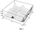
- FIG. 1 schematically shows the position dependent bias across the pixel.
- the estimated impact positions can be perfectly retrieved from the image, that is: no positional information is lost.
- the positional information of each individual estimated impact cannot be retrieved, but the information is incorporated in the image.
- this spreading (effectively a spatial low-pass filter) may be followed by a high-pass filter to improve the image quality (crisp the image) with minimal loss of information.
- the shifting and/or spreading should take place before attributing the information to an image pixel.
- the spreading is done after combining detector images, information is lost. Shifting after combining is not possible. From this inventors concluded that any correction should be performed on the level where single impact events are handled, ideally by shifting the estimated impact position and spreading the information over several image pixels. A similar (although slightly inferior) result can be achieved when the impact is attributed to a group of detector sub-pixels (the sub-pixels used to construct an image) or a group of image pixels.
- the shift or the spreading is performed with a higher resolution than the image representation, the high-frequency information (for example above half of the Nyquist frequency) is better represented, resulting in an improved S/N ratio.
Landscapes
- General Physics & Mathematics (AREA)
- Physics & Mathematics (AREA)
- Health & Medical Sciences (AREA)
- Life Sciences & Earth Sciences (AREA)
- High Energy & Nuclear Physics (AREA)
- Molecular Biology (AREA)
- Spectroscopy & Molecular Physics (AREA)
- Engineering & Computer Science (AREA)
- Multimedia (AREA)
- Signal Processing (AREA)
- Theoretical Computer Science (AREA)
- Measurement Of Radiation (AREA)
- Image Processing (AREA)
Description
- There is a method of detecting particulate radiation using a semiconductor based pixelated detector, the detector pixels having a detector pixel size, the detector sensitive to the particulate radiation, each particle of the particulate radiation causing a multitude of electron/hole pairs in the semiconductor material of the detector, the multitude of electron/hole pairs having a centroid and a centroid extent, the extent of the centroid larger than the detector pixel size, the method comprising:
- A step of intercepting a particle of the particulate radiation,
- A step of estimating the number of electron/hole pairs for a number of adjacent detector pixels,
- A step of estimating the position of the centroid of the number of electron/hole pairs using the estimates of electron/hole pairs in adjacent detector pixels,
- A step of estimating the impact position of the particle using said estimated position of the centroid,
- A step of forming a pixelated image using the estimated position of a multitude of estimated impact positions, the pixelated image consisting of image pixels having an intensity,
- Such a method is known inter alia from the "K2 Direct Detection Cameras", commercially available from Gatan Inc., 5794 W. Las Positas Blvd., Pleasanton, CA 94588, USA.
- The known method describes a pixelated detector intercepting radiation in the form of energetic electrons. Each intercepted electron causes a cloud of electron/hole pairs in the semiconductor material of the detector, thereby causing a signal in the detector pixel(s) where it is detected. As the diameter of the cloud (the centroid) is larger than the diameter of the detector pixels, one impinging electron causes a signal in multiple detector pixels. Using the signal of different detector pixels, an estimate of the impact position is determined with a resolution better than the detector's pixel size, in this case with a resolution of half a detector pixel diameter. This is used to form an image with super-resolution (as the resolution is better than the detector pixel size).
- The method does not disclose how the impact position is determined or estimated. The method has not proven to give results for a resolution other than half a detector pixel or a (multiple of a) whole detector pixel.
- It is noted that in many cases the extent of the centroid can be characterized with a FWHM (Full Width at Half Maximum) diameter.
-
US 2011/0210235A1 discloses an array of pixels for the detection of radiation or particles. Each pixel in the array comprises a radiation receptor for converting radiation or particles into a radiation signal for converting the radiation signal into pulses. The array also comprises a circuit for suppressing those pulses that are compared negatively versus the corresponding pulses in another pixel of the neighborhood for the same one or more criteria. -
US 2015/0260854 A1 discloses method for detecting ionising radiation using a pixelated semi-conductor detector. When the radiation interacts with the detector, the affected pixel is determined, together with the instant of impact for this pixel. A first instant before and a second instant after the instant of impact are deduced from this. The deviations of the signals coming from an assembly of pixels adjacent to the affected point are then measured, with the deviations being measured between the first and second instants. The position of the point of interaction of the radiation with the semi-conductor is estimated from the deviations thus measured. - JAECHEON KIM ET AL, "Three-dimensional signal correction on U1traPeRL CZT detectors", NUCLEAR SCIENCE SYMPOSIUM CONFERENCE RECORD, 2007. NSS '07. IEEE, IEEE, PI, (20071001), ISBN 978-1-4244-0922-8, pages 1289 - 1293, XP031206702 [X] - discloses a study of three-dimensional signal correction on pixellated CdZnTe (CZT) detectors. A depth and lateral correction algorithm has been developed to estimate both the depth of interaction (DOI) and the lateral position underneath the collecting pixel and therefore correct the signal amplitude.
-
US2011/297838A1 is directed to the correction of charge loss in a radiation detector. Correction factors for charge loss may be determined based on depth of interaction and lateral position within a radiation detector of a charge creating event. The correction factors may be applied to subsequently measured signals to correct for the occurrence of charge loss in the measured signals. - The invention intends to provide a method with improved resolution and/or signal-to-noise (S/N) ratio compared to the known method.
- To that end the invention relates to a method according to claim 1.
- Inventors found that the response of a detector pixel to an impinging particle not only depends on different responses between pixels (inter-pixel differences or inter-pixel non-uniformity), but that when estimating the position within the detector pixel the probability that a particle is allocated to a position on the detector pixel (the position dependent bias) is nonuniform: said position dependent bias depends (reproducibly) on the position on the detector pixel and thus introduces an intra-pixel non-uniformity).
This can be explained as follows: assume that the extent of the cloud of electron/hole pairs is smaller than the pixel size, then if the adjacent detector pixels show no electron/hole pairs (all electron/hole pairs are generated within one detector pixel) the position will be allocated to the middle of the detector pixel, as there is no ground to allocate it to another position. Only when the particle hits near the border between two detector pixels (thus causing electron/hole pairs in two detector pixels) a position near the border can be determined, but where along the border is unknown: therefore the position of the particle will be associated to the middle of the border. Only near the corners a true positioning in two directions can be performed. For an extent much larger than the detector pixel size the effect (non-uniformity) smears out. For a centroid size (slightly) larger than the pixel size, the estimated positions cluster near the center of the detector pixel, to a lesser extent to the center of the borders, and to the corners. The peaks of enhanced probability within the pixel are therefore artefacts, resulting (in Fourier space) in a number of additional images located around multiple (even) Nyquist frequencies.Figure 1 gives an example of such enhanced probabilities (in real space, shown for one, square, pixel). - It is noted that these artefacts also occur when the cloud of electron/hole pairs (FWHM) generated in the detector is larger than the size of a pixel of the detector.
- Inventors experimented to find a solution to counter the effect of said position dependent bias. The most obvious solution coming to mind of the skilled artisan is to attach a lower probability to the events near the peaks. In an image this is realized by scaling the intensity of image pixels corresponding to high probability locations. However, this has no physical basis: such scaling implies that only part of a particle detected at the position with a high probability is imaged. Also, part of the information is lost, resulting in an increase in noise. The method according to the invention, with or without improved resolution, can also be used for improved S/N ratio near the Nyquist frequency (the Nyquist frequency governed by the detector pixel size).
- Inventors found that by adjusting the contribution of each impact position to corresponding image pixels to counter the effect of said position dependent bias, the effect of the position dependent bias can be countered.
- The contribution of each estimated impact position to corresponding image pixels may comprise the adjustment of the estimated position within the detector pixel, the adjustment a function of the estimated position within the detector pixel. This may be achieved using a mathematical function, preferably a spline function, or using a look-up table (LUT). When using a LUT, the adjustment of the position may be based on one LUT value, or on an interpolation of more than one LUT values. This results in an adjusted estimated position.
- The contribution of each estimated impact position to corresponding image pixels comprises adding intensity to more than one image pixels, the adding a function of the estimated position (or adjusted estimated position) within the detector pixel.
- The adding of intensity to more than one image pixel may be derived using a LUT, the LUT values a function of the estimated position within the pixel. The LUT may show a large number of values, each value corresponding to a rounded estimated position. This introduces a (small) rounding in positional information. Preferably the values are derived from an interpolation in the LUT, the interpolation based on the estimated position within the detector pixel. Less rounding is then to be expected. Alternatively the adding of intensity may be derived from a mathematical function, preferably a spline function.
- In yet another embodiment the particulate radiation is particulate radiation from the group of electrons, ions, and X-rays
- It is noted that the invention does not relate to PALM or dSTORM, as these super-resolution methods detect a multitude of particles captured by one pixel, each particle a photon of visible light, each photon causing (at most) one electron/hole pair, followed by determining the centroid of several adjacent pixels.
- It is further noted that for Gatan's S2 camera the only known super-resolution setting is half the pixel size. Nowhere does Gatan disclose that the estimated position is shifted to counter clustering at half the pixel size. As the position dependent bias error introduces a non-uniformity at twice the pixel size, this is hard to detect when the super-resolution is set to exactly half the pixel size
- The method is compatible with particulate radiation from the group of electron, ions, and X-ray photons.
- In an embodiment the method further comprises obtaining a pixelated image using the estimates of the impact position of a multitude of particles, the estimate of the impact position of each particle contributing to the intensity of several image pixels.
- It is noted that when attributing the detected particle to only one pixel of the image, Moire effects and interferences can occur. Inventors found that to avoid this, the contribution of each particle is best spread out over several pixels.
- It is noted that as long as the point spread function (PSF) used to spread out the contribution is known, this is a reversible method and the original position can be derived by deconvolution of the image intensities and the (known) PSF.
- Preferably the several image pixels are adjacent image pixels, but the amount of pixels need not be limited to the image pixels directly bordering the pixel corresponding to the estimated impact position.
- It is noted that although particularly useful for the method of the invention, also other methods for detecting particulate radiation may benefit from obtaining a pixelated image using the estimates of the impact position of a multitude of particles, the estimate of the impact position of each particle contributing to the intensity of several image pixels.
- The invention is now elucidated using
figure 1 . - To that end
figure 1 schematically shows the position dependent bias across the pixel. This concerns actual measurements where a large number of electrons impacted on a pixelated detector, the pixelated detector having a pixel size of 14 x 14 µm2, while the FWHM size of the cloud of electron/hole pairs is estimated to be 22 µm (1.6 times the pixel size). Note that the irradiation was uniform. Clearly the estimated position is not uniform, indicating that there is a position dependent bias. This position dependent bias can be countered by shifting of the position, using a vector field for each sub-pixel, or using a function where the adjusted position (u,v) is a function of the detected position (x,y), thus (u,v) = F(x,y), or it can be countered by spreading the contribution of one event (impact) over several image pixels or sub-pixels (representing the impact position as a 'blob' contributing to several detector sub-pixels, the blob a position dependent blob. It is noted that one sub-pixel may show a one-to-one relation to an image pixel, or several sub-pixels may contribute to one image pixel. In any event it is favorable to spread the information representing one estimated impact is spread over several image pixels. This spreading over several image pixels (further referred to as spreading) is in itself counter-intuitive, as it gives a result similar to blurring, but the spreading eliminates (or greatly reduces) Moire-effects and interferences. - It is noted that when using appropriate spreading, and assuming the image is a sparse image (so: in most cases one or no impacts per image pixel) the estimated impact positions can be perfectly retrieved from the image, that is: no positional information is lost. In case of a non-sparse image the positional information of each individual estimated impact cannot be retrieved, but the information is incorporated in the image.
- It is further noted that this spreading (effectively a spatial low-pass filter) may be followed by a high-pass filter to improve the image quality (crisp the image) with minimal loss of information.
- The shifting and/or spreading should take place before attributing the information to an image pixel. When the spreading is done after combining detector images, information is lost. Shifting after combining is not possible. From this inventors concluded that any correction should be performed on the level where single impact events are handled, ideally by shifting the estimated impact position and spreading the information over several image pixels. A similar (although slightly inferior) result can be achieved when the impact is attributed to a group of detector sub-pixels (the sub-pixels used to construct an image) or a group of image pixels.
- If the shift or the spreading is performed with a higher resolution than the image representation, the high-frequency information (for example above half of the Nyquist frequency) is better represented, resulting in an improved S/N ratio.
- It is noted that all this does not take away the need to correct for before mentioned inter-pixel differences.
- Summarizing, when detecting particulate radiation, such as electrons, with a pixelated detector, a cloud of electron/hole pairs is formed in the detector. Using the signal caused by this cloud of electron/hole pairs a position of the impact is estimated. Inventors found that, when the size of the cloud is comparable to the pixel size, or much smaller, the estimated position shows a strong bias to the center of the pixel and the corners, as well to the middle of the borders. This hinders forming an image with super-resolution. By shifting the position or by attributing the electron to several sub-pixels this bias can be countered, resulting in a more truthful representation. It is noted that shifting and/or spreading should take place before attributing the information to an image pixel, and before adding the events per sub-pixel. When the spreading is done after combining detector images, information is lost. It is noted that shifting after combining detector images is not possible.
Claims (5)
- A method of detecting particulate radiation using a semiconductor based pixelated detector, the detector pixels having a detector pixel size, the detector sensitive to the particulate radiation, each particle of the particulate radiation causing a multitude of electron/hole pairs in the semiconductor material of the detector, the multitude of electron/hole pairs having a centroid and a centroid extent, the extent of the centroid extent larger than the detector pixel size, the method comprising:• A step of intercepting a particle of the particulate radiation,• A step of estimating the number of electron/hole pairs for a number of adjacent detector pixels,• A step of estimating the position of the centroid of the number of electron/hole pairs using the estimates of electron/hole pairs in adjacent detector pixels,• A step of estimating the impact position of the particle using said estimated position of the centroid,• A step of forming a pixelated image using the estimated position of a multitude of estimated impact positions, the pixelated image consisting of image pixels having an intensity,
wherein,• When estimating the impact position said estimate has a position dependent bias depending on the position within the detector pixel, and• The contribution of each estimated impact position to corresponding image pixels is adjusted to counter the effect of said position dependent bias, characterized in that, the adjustment of the contribution of each estimated impact position to corresponding image pixels comprises directly adding intensity to several image pixels,
thereby spreading out the contribution of each estimated impact position to said several image pixels. - The method of claim 1 in which the adjustment of the contribution of each estimated impact position to corresponding image pixels comprises the adjustment of the estimated position, the adjustment a function of the estimated impact position relative to the detector pixel.
- The method of claim 1 or claim 2 in which the function is a function from the group of spline functions.
- The method of any of claims 1 or claim 2 in which the function is stored in a look-up table (LUT).
- The method of any of the preceding claims in which the particulate radiation is particulate radiation from the group of electrons, ions, and X-rays.
Applications Claiming Priority (2)
| Application Number | Priority Date | Filing Date | Title |
|---|---|---|---|
| EP15194118 | 2015-11-11 | ||
| EP16161322.9A EP3223039A1 (en) | 2016-03-21 | 2016-03-21 | Method for detecting particulate radiation |
Publications (2)
| Publication Number | Publication Date |
|---|---|
| EP3168651A1 EP3168651A1 (en) | 2017-05-17 |
| EP3168651B1 true EP3168651B1 (en) | 2020-02-12 |
Family
ID=57281106
Family Applications (1)
| Application Number | Title | Priority Date | Filing Date |
|---|---|---|---|
| EP16198005.7A Active EP3168651B1 (en) | 2015-11-11 | 2016-11-09 | Method for detecting particulate radiation |
Country Status (4)
| Country | Link |
|---|---|
| US (2) | US10122946B2 (en) |
| EP (1) | EP3168651B1 (en) |
| JP (1) | JP6920808B2 (en) |
| CN (1) | CN106680860B (en) |
Families Citing this family (6)
| Publication number | Priority date | Publication date | Assignee | Title |
|---|---|---|---|---|
| US10122946B2 (en) * | 2015-11-11 | 2018-11-06 | Fei Company | Method for detecting particulate radiation |
| GB2569371B (en) * | 2017-12-15 | 2022-01-12 | Lightpoint Medical Ltd | Direct detection and imaging of charged particles from a radiopharmaceutical |
| CN108926356B (en) * | 2018-05-31 | 2022-03-25 | 上海联影医疗科技股份有限公司 | Detector photon arrival information determination method, device and medical device |
| EP3780065A1 (en) | 2019-08-12 | 2021-02-17 | FEI Company | Charged particle microscope with a pixelated detector, and method of detecting particulate radiation using a pixelated detector |
| CN113125471B (en) * | 2021-03-31 | 2023-06-27 | 武汉联影生命科学仪器有限公司 | Scanning system and scanning control method |
| KR102635483B1 (en) * | 2021-10-07 | 2024-02-08 | 한국표준과학연구원 | Deconvolution method for image observed in charged particle beam apparatus, image process apparatus and charged particle beam apparatus comprising image process apparatus |
Family Cites Families (20)
| Publication number | Priority date | Publication date | Assignee | Title |
|---|---|---|---|---|
| US4803368A (en) * | 1987-12-28 | 1989-02-07 | Siemens Medical Laboratories, Inc. | Assembly and method for monitoring the lateral position of a beam of ionizing radiation |
| WO1996028751A1 (en) | 1995-03-16 | 1996-09-19 | Philips Electronics N.V. | Method for particle wave reconstruction in a particle-optical apparatus |
| EP0795197B1 (en) | 1995-10-03 | 2000-02-02 | Koninklijke Philips Electronics N.V. | Method of reconstructing an image in a particle-optical apparatus |
| WO2007077286A1 (en) * | 2006-01-05 | 2007-07-12 | Artto Aurola | Semiconductor radiation detector detecting visible light |
| WO2009125476A1 (en) * | 2008-04-08 | 2009-10-15 | 株式会社島津製作所 | Radiation detector |
| US8440957B2 (en) | 2009-02-25 | 2013-05-14 | Bart Dierickx | Counting pixel with good dynamic range properties |
| US8749662B2 (en) * | 2009-04-16 | 2014-06-10 | Nvidia Corporation | System and method for lens shading image correction |
| US8405038B2 (en) * | 2009-12-30 | 2013-03-26 | General Electric Company | Systems and methods for providing a shared charge in pixelated image detectors |
| US8466420B2 (en) | 2010-06-04 | 2013-06-18 | General Electric Company | Charge loss correction |
| EP2461347A1 (en) | 2010-12-06 | 2012-06-06 | Fei Company | Detector system for transmission electron microscope |
| EP2518687B1 (en) | 2011-04-26 | 2013-04-24 | FEI Company | Method for determining a reconstructed image using a particle-optical apparatus |
| EP2579575A1 (en) | 2011-10-06 | 2013-04-10 | FEI Company | Method for acquiring data with an image sensor |
| EP2584362A1 (en) | 2011-10-18 | 2013-04-24 | FEI Company | Scanning method for scanning a sample with a probe |
| EP2690648B1 (en) | 2012-07-26 | 2014-10-15 | Fei Company | Method of preparing and imaging a lamella in a particle-optical apparatus |
| FR2996648A1 (en) | 2012-10-08 | 2014-04-11 | Commissariat Energie Atomique | METHOD AND DEVICE FOR DETECTING IONIZING RADIATION BY A PIXELLIZED PHOTODETECTOR |
| EP2738786A1 (en) | 2012-11-29 | 2014-06-04 | Fei Company | Method of performing tomographic imaging of a sample in a charged-particle microscope |
| EP2879156A1 (en) | 2013-12-02 | 2015-06-03 | Fei Company | Charged-particle microscopy with enhanced electron detection |
| EP2887381B1 (en) | 2013-12-18 | 2016-09-21 | Fei Company | Method of investigating the wavefront of a charged-particle beam |
| EP3062125A1 (en) | 2015-02-26 | 2016-08-31 | Fei Company | Pulse processing |
| US10122946B2 (en) * | 2015-11-11 | 2018-11-06 | Fei Company | Method for detecting particulate radiation |
-
2016
- 2016-07-25 US US15/218,465 patent/US10122946B2/en active Active
- 2016-11-09 EP EP16198005.7A patent/EP3168651B1/en active Active
- 2016-11-10 JP JP2016219603A patent/JP6920808B2/en active Active
- 2016-11-11 CN CN201611271117.9A patent/CN106680860B/en active Active
-
2018
- 2018-11-05 US US16/180,242 patent/US10389955B2/en active Active
Non-Patent Citations (1)
| Title |
|---|
| None * |
Also Published As
| Publication number | Publication date |
|---|---|
| US20190075258A1 (en) | 2019-03-07 |
| CN106680860B (en) | 2022-05-17 |
| US20170134674A1 (en) | 2017-05-11 |
| CN106680860A (en) | 2017-05-17 |
| EP3168651A1 (en) | 2017-05-17 |
| JP6920808B2 (en) | 2021-08-18 |
| JP2017090460A (en) | 2017-05-25 |
| US10122946B2 (en) | 2018-11-06 |
| US10389955B2 (en) | 2019-08-20 |
Similar Documents
| Publication | Publication Date | Title |
|---|---|---|
| US10389955B2 (en) | Method for detecting particulate radiation | |
| Tremsin et al. | High Resolution Photon Counting With MCP-Timepix Quad Parallel Readout Operating at $> 1~{\rm KHz} $ Frame Rates | |
| US9191556B2 (en) | Imaging array having photodiodes with different light sensitivities and associated image restoration methods | |
| US10397465B2 (en) | Extended or full-density phase-detection autofocus control | |
| JP4121780B2 (en) | Method for reducing motion blur in digital images | |
| US7876363B2 (en) | Methods, systems and apparatuses for high-quality green imbalance compensation in images | |
| EP3093819B1 (en) | Imaging apparatus, imaging system, and signal processing method | |
| US20150362698A1 (en) | Image Sensor for Depth Estimation | |
| JP2011071981A (en) | Modulator, device for obtaining optical field data using the modulator, and device and method for processing optical field data using the modulator | |
| US11195692B2 (en) | System for electron diffraction analysis | |
| CN102970463A (en) | Image processing device, image processing method and program | |
| JP7695267B2 (en) | Improved camera for electron diffraction pattern analysis. | |
| WO2015198875A1 (en) | Image sensor, calculation method, and electronic device | |
| JP2021523364A (en) | Photon counting spectral CT | |
| US20170257583A1 (en) | Image processing device and control method thereof | |
| JP2020518911A (en) | Image sequence alignment system and method | |
| JP2008514134A (en) | Extended effective dynamic range | |
| EP3223039A1 (en) | Method for detecting particulate radiation | |
| JP5933690B2 (en) | Image processing apparatus and method, and image processing program | |
| US20070287218A1 (en) | Digital filter | |
| US20190156462A1 (en) | Aberrant pixel detection and correction | |
| Zhang et al. | low-light color reproduction by selective averaging in multi-aperture camera with bayer color-filter low-noise CMOS image sensors | |
| Hirakawa et al. | Advancing the digital camera pipeline for mobile multimedia: Key challenges from a signal processing perspective | |
| Maj et al. | Minimization of charge sharing effect in silicon hybrid pixel X-ray detectors based on pattern recognition algorithm |
Legal Events
| Date | Code | Title | Description |
|---|---|---|---|
| PUAI | Public reference made under article 153(3) epc to a published international application that has entered the european phase |
Free format text: ORIGINAL CODE: 0009012 |
|
| STAA | Information on the status of an ep patent application or granted ep patent |
Free format text: STATUS: THE APPLICATION HAS BEEN PUBLISHED |
|
| AK | Designated contracting states |
Kind code of ref document: A1 Designated state(s): AL AT BE BG CH CY CZ DE DK EE ES FI FR GB GR HR HU IE IS IT LI LT LU LV MC MK MT NL NO PL PT RO RS SE SI SK SM TR |
|
| AX | Request for extension of the european patent |
Extension state: BA ME |
|
| STAA | Information on the status of an ep patent application or granted ep patent |
Free format text: STATUS: REQUEST FOR EXAMINATION WAS MADE |
|
| 17P | Request for examination filed |
Effective date: 20171107 |
|
| RBV | Designated contracting states (corrected) |
Designated state(s): AL AT BE BG CH CY CZ DE DK EE ES FI FR GB GR HR HU IE IS IT LI LT LU LV MC MK MT NL NO PL PT RO RS SE SI SK SM TR |
|
| GRAP | Despatch of communication of intention to grant a patent |
Free format text: ORIGINAL CODE: EPIDOSNIGR1 |
|
| STAA | Information on the status of an ep patent application or granted ep patent |
Free format text: STATUS: GRANT OF PATENT IS INTENDED |
|
| INTG | Intention to grant announced |
Effective date: 20191022 |
|
| RIN1 | Information on inventor provided before grant (corrected) |
Inventor name: YU, LINGBO Inventor name: JANSSEN, BART Inventor name: KUIJPER, MAARTEN Inventor name: FRANKEN, ERIK |
|
| GRAS | Grant fee paid |
Free format text: ORIGINAL CODE: EPIDOSNIGR3 |
|
| GRAA | (expected) grant |
Free format text: ORIGINAL CODE: 0009210 |
|
| STAA | Information on the status of an ep patent application or granted ep patent |
Free format text: STATUS: THE PATENT HAS BEEN GRANTED |
|
| AK | Designated contracting states |
Kind code of ref document: B1 Designated state(s): AL AT BE BG CH CY CZ DE DK EE ES FI FR GB GR HR HU IE IS IT LI LT LU LV MC MK MT NL NO PL PT RO RS SE SI SK SM TR |
|
| REG | Reference to a national code |
Ref country code: GB Ref legal event code: FG4D |
|
| REG | Reference to a national code |
Ref country code: CH Ref legal event code: EP |
|
| REG | Reference to a national code |
Ref country code: AT Ref legal event code: REF Ref document number: 1232876 Country of ref document: AT Kind code of ref document: T Effective date: 20200215 |
|
| REG | Reference to a national code |
Ref country code: DE Ref legal event code: R096 Ref document number: 602016029440 Country of ref document: DE |
|
| REG | Reference to a national code |
Ref country code: IE Ref legal event code: FG4D |
|
| PG25 | Lapsed in a contracting state [announced via postgrant information from national office to epo] |
Ref country code: RS Free format text: LAPSE BECAUSE OF FAILURE TO SUBMIT A TRANSLATION OF THE DESCRIPTION OR TO PAY THE FEE WITHIN THE PRESCRIBED TIME-LIMIT Effective date: 20200212 Ref country code: FI Free format text: LAPSE BECAUSE OF FAILURE TO SUBMIT A TRANSLATION OF THE DESCRIPTION OR TO PAY THE FEE WITHIN THE PRESCRIBED TIME-LIMIT Effective date: 20200212 Ref country code: NO Free format text: LAPSE BECAUSE OF FAILURE TO SUBMIT A TRANSLATION OF THE DESCRIPTION OR TO PAY THE FEE WITHIN THE PRESCRIBED TIME-LIMIT Effective date: 20200512 |
|
| REG | Reference to a national code |
Ref country code: LT Ref legal event code: MG4D |
|
| REG | Reference to a national code |
Ref country code: NL Ref legal event code: MP Effective date: 20200212 |
|
| PG25 | Lapsed in a contracting state [announced via postgrant information from national office to epo] |
Ref country code: SE Free format text: LAPSE BECAUSE OF FAILURE TO SUBMIT A TRANSLATION OF THE DESCRIPTION OR TO PAY THE FEE WITHIN THE PRESCRIBED TIME-LIMIT Effective date: 20200212 Ref country code: IS Free format text: LAPSE BECAUSE OF FAILURE TO SUBMIT A TRANSLATION OF THE DESCRIPTION OR TO PAY THE FEE WITHIN THE PRESCRIBED TIME-LIMIT Effective date: 20200612 Ref country code: BG Free format text: LAPSE BECAUSE OF FAILURE TO SUBMIT A TRANSLATION OF THE DESCRIPTION OR TO PAY THE FEE WITHIN THE PRESCRIBED TIME-LIMIT Effective date: 20200512 Ref country code: HR Free format text: LAPSE BECAUSE OF FAILURE TO SUBMIT A TRANSLATION OF THE DESCRIPTION OR TO PAY THE FEE WITHIN THE PRESCRIBED TIME-LIMIT Effective date: 20200212 Ref country code: GR Free format text: LAPSE BECAUSE OF FAILURE TO SUBMIT A TRANSLATION OF THE DESCRIPTION OR TO PAY THE FEE WITHIN THE PRESCRIBED TIME-LIMIT Effective date: 20200513 Ref country code: LV Free format text: LAPSE BECAUSE OF FAILURE TO SUBMIT A TRANSLATION OF THE DESCRIPTION OR TO PAY THE FEE WITHIN THE PRESCRIBED TIME-LIMIT Effective date: 20200212 |
|
| PG25 | Lapsed in a contracting state [announced via postgrant information from national office to epo] |
Ref country code: NL Free format text: LAPSE BECAUSE OF FAILURE TO SUBMIT A TRANSLATION OF THE DESCRIPTION OR TO PAY THE FEE WITHIN THE PRESCRIBED TIME-LIMIT Effective date: 20200212 |
|
| PG25 | Lapsed in a contracting state [announced via postgrant information from national office to epo] |
Ref country code: RO Free format text: LAPSE BECAUSE OF FAILURE TO SUBMIT A TRANSLATION OF THE DESCRIPTION OR TO PAY THE FEE WITHIN THE PRESCRIBED TIME-LIMIT Effective date: 20200212 Ref country code: SK Free format text: LAPSE BECAUSE OF FAILURE TO SUBMIT A TRANSLATION OF THE DESCRIPTION OR TO PAY THE FEE WITHIN THE PRESCRIBED TIME-LIMIT Effective date: 20200212 Ref country code: SM Free format text: LAPSE BECAUSE OF FAILURE TO SUBMIT A TRANSLATION OF THE DESCRIPTION OR TO PAY THE FEE WITHIN THE PRESCRIBED TIME-LIMIT Effective date: 20200212 Ref country code: EE Free format text: LAPSE BECAUSE OF FAILURE TO SUBMIT A TRANSLATION OF THE DESCRIPTION OR TO PAY THE FEE WITHIN THE PRESCRIBED TIME-LIMIT Effective date: 20200212 Ref country code: DK Free format text: LAPSE BECAUSE OF FAILURE TO SUBMIT A TRANSLATION OF THE DESCRIPTION OR TO PAY THE FEE WITHIN THE PRESCRIBED TIME-LIMIT Effective date: 20200212 Ref country code: PT Free format text: LAPSE BECAUSE OF FAILURE TO SUBMIT A TRANSLATION OF THE DESCRIPTION OR TO PAY THE FEE WITHIN THE PRESCRIBED TIME-LIMIT Effective date: 20200705 Ref country code: LT Free format text: LAPSE BECAUSE OF FAILURE TO SUBMIT A TRANSLATION OF THE DESCRIPTION OR TO PAY THE FEE WITHIN THE PRESCRIBED TIME-LIMIT Effective date: 20200212 Ref country code: ES Free format text: LAPSE BECAUSE OF FAILURE TO SUBMIT A TRANSLATION OF THE DESCRIPTION OR TO PAY THE FEE WITHIN THE PRESCRIBED TIME-LIMIT Effective date: 20200212 |
|
| REG | Reference to a national code |
Ref country code: DE Ref legal event code: R097 Ref document number: 602016029440 Country of ref document: DE |
|
| REG | Reference to a national code |
Ref country code: AT Ref legal event code: MK05 Ref document number: 1232876 Country of ref document: AT Kind code of ref document: T Effective date: 20200212 |
|
| PLBE | No opposition filed within time limit |
Free format text: ORIGINAL CODE: 0009261 |
|
| STAA | Information on the status of an ep patent application or granted ep patent |
Free format text: STATUS: NO OPPOSITION FILED WITHIN TIME LIMIT |
|
| 26N | No opposition filed |
Effective date: 20201113 |
|
| PG25 | Lapsed in a contracting state [announced via postgrant information from national office to epo] |
Ref country code: AT Free format text: LAPSE BECAUSE OF FAILURE TO SUBMIT A TRANSLATION OF THE DESCRIPTION OR TO PAY THE FEE WITHIN THE PRESCRIBED TIME-LIMIT Effective date: 20200212 Ref country code: IT Free format text: LAPSE BECAUSE OF FAILURE TO SUBMIT A TRANSLATION OF THE DESCRIPTION OR TO PAY THE FEE WITHIN THE PRESCRIBED TIME-LIMIT Effective date: 20200212 |
|
| PG25 | Lapsed in a contracting state [announced via postgrant information from national office to epo] |
Ref country code: PL Free format text: LAPSE BECAUSE OF FAILURE TO SUBMIT A TRANSLATION OF THE DESCRIPTION OR TO PAY THE FEE WITHIN THE PRESCRIBED TIME-LIMIT Effective date: 20200212 Ref country code: SI Free format text: LAPSE BECAUSE OF FAILURE TO SUBMIT A TRANSLATION OF THE DESCRIPTION OR TO PAY THE FEE WITHIN THE PRESCRIBED TIME-LIMIT Effective date: 20200212 |
|
| PG25 | Lapsed in a contracting state [announced via postgrant information from national office to epo] |
Ref country code: MC Free format text: LAPSE BECAUSE OF FAILURE TO SUBMIT A TRANSLATION OF THE DESCRIPTION OR TO PAY THE FEE WITHIN THE PRESCRIBED TIME-LIMIT Effective date: 20200212 |
|
| REG | Reference to a national code |
Ref country code: CH Ref legal event code: PL |
|
| PG25 | Lapsed in a contracting state [announced via postgrant information from national office to epo] |
Ref country code: LU Free format text: LAPSE BECAUSE OF NON-PAYMENT OF DUE FEES Effective date: 20201109 |
|
| REG | Reference to a national code |
Ref country code: BE Ref legal event code: MM Effective date: 20201130 |
|
| PG25 | Lapsed in a contracting state [announced via postgrant information from national office to epo] |
Ref country code: LI Free format text: LAPSE BECAUSE OF NON-PAYMENT OF DUE FEES Effective date: 20201130 Ref country code: CH Free format text: LAPSE BECAUSE OF NON-PAYMENT OF DUE FEES Effective date: 20201130 |
|
| PG25 | Lapsed in a contracting state [announced via postgrant information from national office to epo] |
Ref country code: IE Free format text: LAPSE BECAUSE OF NON-PAYMENT OF DUE FEES Effective date: 20201109 |
|
| PG25 | Lapsed in a contracting state [announced via postgrant information from national office to epo] |
Ref country code: TR Free format text: LAPSE BECAUSE OF FAILURE TO SUBMIT A TRANSLATION OF THE DESCRIPTION OR TO PAY THE FEE WITHIN THE PRESCRIBED TIME-LIMIT Effective date: 20200212 Ref country code: MT Free format text: LAPSE BECAUSE OF FAILURE TO SUBMIT A TRANSLATION OF THE DESCRIPTION OR TO PAY THE FEE WITHIN THE PRESCRIBED TIME-LIMIT Effective date: 20200212 Ref country code: CY Free format text: LAPSE BECAUSE OF FAILURE TO SUBMIT A TRANSLATION OF THE DESCRIPTION OR TO PAY THE FEE WITHIN THE PRESCRIBED TIME-LIMIT Effective date: 20200212 |
|
| PG25 | Lapsed in a contracting state [announced via postgrant information from national office to epo] |
Ref country code: MK Free format text: LAPSE BECAUSE OF FAILURE TO SUBMIT A TRANSLATION OF THE DESCRIPTION OR TO PAY THE FEE WITHIN THE PRESCRIBED TIME-LIMIT Effective date: 20200212 Ref country code: AL Free format text: LAPSE BECAUSE OF FAILURE TO SUBMIT A TRANSLATION OF THE DESCRIPTION OR TO PAY THE FEE WITHIN THE PRESCRIBED TIME-LIMIT Effective date: 20200212 |
|
| PG25 | Lapsed in a contracting state [announced via postgrant information from national office to epo] |
Ref country code: BE Free format text: LAPSE BECAUSE OF NON-PAYMENT OF DUE FEES Effective date: 20201130 |
|
| P01 | Opt-out of the competence of the unified patent court (upc) registered |
Effective date: 20230524 |
|
| PGFP | Annual fee paid to national office [announced via postgrant information from national office to epo] |
Ref country code: DE Payment date: 20251010 Year of fee payment: 10 |
|
| PGFP | Annual fee paid to national office [announced via postgrant information from national office to epo] |
Ref country code: GB Payment date: 20251114 Year of fee payment: 10 |
|
| PGFP | Annual fee paid to national office [announced via postgrant information from national office to epo] |
Ref country code: FR Payment date: 20251111 Year of fee payment: 10 |
|
| PGFP | Annual fee paid to national office [announced via postgrant information from national office to epo] |
Ref country code: CZ Payment date: 20251029 Year of fee payment: 10 |