EP3168593A1 - Simulator for positioning the seats in a bus - Google Patents
Simulator for positioning the seats in a bus Download PDFInfo
- Publication number
- EP3168593A1 EP3168593A1 EP16198540.3A EP16198540A EP3168593A1 EP 3168593 A1 EP3168593 A1 EP 3168593A1 EP 16198540 A EP16198540 A EP 16198540A EP 3168593 A1 EP3168593 A1 EP 3168593A1
- Authority
- EP
- European Patent Office
- Prior art keywords
- seats
- simulator
- seat
- bus
- driving device
- Prior art date
- Legal status (The legal status is an assumption and is not a legal conclusion. Google has not performed a legal analysis and makes no representation as to the accuracy of the status listed.)
- Granted
Links
Images


Classifications
-
- G—PHYSICS
- G01—MEASURING; TESTING
- G01M—TESTING STATIC OR DYNAMIC BALANCE OF MACHINES OR STRUCTURES; TESTING OF STRUCTURES OR APPARATUS, NOT OTHERWISE PROVIDED FOR
- G01M99/00—Subject matter not provided for in other groups of this subclass
- G01M99/001—Testing of furniture, e.g. seats or mattresses
-
- B—PERFORMING OPERATIONS; TRANSPORTING
- B60—VEHICLES IN GENERAL
- B60N—SEATS SPECIALLY ADAPTED FOR VEHICLES; VEHICLE PASSENGER ACCOMMODATION NOT OTHERWISE PROVIDED FOR
- B60N2/00—Seats specially adapted for vehicles; Arrangement or mounting of seats in vehicles
- B60N2/005—Arrangement or mounting of seats in vehicles, e.g. dismountable auxiliary seats
- B60N2/01—Arrangement of seats relative to one another
-
- G—PHYSICS
- G01—MEASURING; TESTING
- G01M—TESTING STATIC OR DYNAMIC BALANCE OF MACHINES OR STRUCTURES; TESTING OF STRUCTURES OR APPARATUS, NOT OTHERWISE PROVIDED FOR
- G01M17/00—Testing of vehicles
- G01M17/007—Wheeled or endless-tracked vehicles
Definitions
- the present invention concerns a simulator, in particular a simulator for the positioning of the seats in a bus.
- One of the main design requirements of the internal spaces of buses is to guarantee the comfort of the passenger during a trip.
- the disposition of seats in a bus has become very important because it is necessary to allow the passenger to perform comfortably a variety of activities such as reading a paper, using a laptop or a tablet computer, using a reclining table or visualizing a screen both placed on the rear of the seat in front of the passenger or, further, reclining the seat during long trips.
- a further production-related need is to propose on the market a limited number of configurations in order to maintain a high standardization of the dispositions of the seats, and to obtain therefore scale economies in the bus production.
- An aim of the present invention is to satisfy the above mentioned need.
- Frame 2 comprises a plurality of section bars 7 linked together to form a structure having a substantially rectangular shape.
- Frame 2 comprises, in a substantially central position, a portion 9 lowered with respect to a rear end portion 11a and a front end portion 11b, and defining a space 8.
- Lowered portion 9 substantially comprises a couple of longitudinal tracks 10.
- Driving device 4 is positioned within space 8 and slides on tracks 10 between a couple of stops 12 fixed to portions 11a, 11b respectively.
- Fixed seats 3a are fixed to rear portion 11a and movable seats 3b are fixed to driving device 4.
- Seats 3a, 3b are fixed by releasable links, e.g. by pegs 13 extending vertically from the rear portion 11a and, respectively, from the driving device 4, and configured to engage respective holes (not shown) of a support structure 3c of the seats 3.
- seats 3a, 3b can be linked by means of threaded connections or any other known type of releasable connections.
- Seats 3 can be selected in a range of available seats models.
- Driving device 4 comprises a couple of longitudinal bars 15 linked together by means of a couple of transversal bars 16. Bars 15 slide freely on tracks 10 of the lowered portion 9 of the frame 2, conveniently with the interposition of low friction material or rolling bearing guides.
- Driving device 4 further comprises a central longitudinal rod 17 conveniently fixed to both transversal bars and linking the latter to an output element 20 of an actuator 21.
- the actuator 21 may be a linear electric motor, a hydraulic or pneumatic cylinder or also a rotating electric motor provided with a suitable gearing.
- Actuator 21 is conveniently placed in the rear portion 11a. Actuator 21 is activated by control device 5 which is also preferably placed in the rear portion 11a.
- Control device 5 comprises a computer unit 25 and a distance sensor 24 for detecting an entity correlated with the distance of movable seats 3b respect to fixed seats 3a.
- Sensor 24 can be any distance sensor, preferably an ultrasound sensor.
- Computer unit 25 is configured to activate actuator 21 in response to input signals 28 received from a remote command device 26, i.e. a tablet or a laptop computer, and reference signals 27 received from sensor 24.
- a remote command device 26 i.e. a tablet or a laptop computer
- reference signals 27 received from sensor 24.
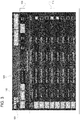
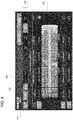
- the remote device 26 it is possible to visualize in a clear and precise manner the possible configurations of the seats 3a, 3b by means of a dedicated software provided with a graphical interface as the one shown in Figs. 3 and 4 .
- the graphical interface allows to select different configurations options of the bus seats, such as:
- the graphical interface moves to a new screen where such selected configurations are listed and are individually selectable to display a graphical scheme of the disposition of the seats in a bus, in order to easily compare the various configurations.
- the remote device 30 sends an input signal 28 to the computer unit 25, which commands the displacement of driving device 4 until it reaches the desired position of movable seats 3b with respect to fixed seats 3a, detected by sensor 25, by means of a closed loop circuit control.
- Simulator 1 allows a potential customer to try in reality the positioning of two pairs of seats 3 in a simple and economic manner in order to compare different configurations; this comparison is rapidly achieved through a graphical interface.
- driving device 4 or control device 5 can be substituted by equivalent devices with similar functions.
Landscapes
- Engineering & Computer Science (AREA)
- Physics & Mathematics (AREA)
- General Physics & Mathematics (AREA)
- Aviation & Aerospace Engineering (AREA)
- Transportation (AREA)
- Mechanical Engineering (AREA)
- Management, Administration, Business Operations System, And Electronic Commerce (AREA)
- Traffic Control Systems (AREA)
Abstract
Description
- The present invention concerns a simulator, in particular a simulator for the positioning of the seats in a bus.
- One of the main design requirements of the internal spaces of buses is to guarantee the comfort of the passenger during a trip. In particular, the disposition of seats in a bus has become very important because it is necessary to allow the passenger to perform comfortably a variety of activities such as reading a paper, using a laptop or a tablet computer, using a reclining table or visualizing a screen both placed on the rear of the seat in front of the passenger or, further, reclining the seat during long trips.
- Because of the variety of operations that could be performed by the passenger with respect to the past, the problem arises to find a reasonable compromise between the ergonomics and capacity of the bus.
- A further production-related need is to propose on the market a limited number of configurations in order to maintain a high standardization of the dispositions of the seats, and to obtain therefore scale economies in the bus production.
- Therefore, the need is felt to simulate in reality the disposition of the seats to test the ergonomics of a plurality of possible configurations.
- An aim of the present invention is to satisfy the above mentioned need.
- The aforementioned aim is reached by a simulator as claimed in
claim 1. - For a better understanding of the present invention, a preferred embodiment is described in the following, by way of a non-limiting example, with reference to the attached drawings wherein:
-
Fig. 1 is a schematic lateral view illustrating a simulator for the configuration of seats according to the present invention; -
Fig. 2 is a schematic top-view illustrating the operation of the simulator ofFig. 1 ; and -
Figs. 3 and4 are examples of a graphical interface of a control device of the simulator ofFig. 1 . -
Figs. 1 and2 disclose asimulator 1 for the positioning of bus seats essentially comprising:- a
frame 2; - a plurality of
seats 3, in the illustrated embodiment a pair of fixedseats 3a arranged side by side and a pair ofmovable seats 3b arranged side by side and placed in front of the pair of fixedseats 3a; - a
driving device 4 configured to regulate the position of themovable seats 3b with respect to thefixed seats 3a; and - a
control device 5 for controlling thehandling device 4.
- a
-
Frame 2 comprises a plurality ofsection bars 7 linked together to form a structure having a substantially rectangular shape.Frame 2 comprises, in a substantially central position, aportion 9 lowered with respect to arear end portion 11a and afront end portion 11b, and defining a space 8. - Lowered
portion 9 substantially comprises a couple oflongitudinal tracks 10.Driving device 4 is positioned within space 8 and slides ontracks 10 between a couple ofstops 12 fixed toportions - Fixed
seats 3a are fixed torear portion 11a andmovable seats 3b are fixed to drivingdevice 4. -
Seats pegs 13 extending vertically from therear portion 11a and, respectively, from thedriving device 4, and configured to engage respective holes (not shown) of asupport structure 3c of theseats 3. Alternatively,seats -
Seats 3 can be selected in a range of available seats models. -
Driving device 4 comprises a couple oflongitudinal bars 15 linked together by means of a couple oftransversal bars 16.Bars 15 slide freely ontracks 10 of the loweredportion 9 of theframe 2, conveniently with the interposition of low friction material or rolling bearing guides. -
Driving device 4 further comprises a centrallongitudinal rod 17 conveniently fixed to both transversal bars and linking the latter to anoutput element 20 of anactuator 21. - The
actuator 21 may be a linear electric motor, a hydraulic or pneumatic cylinder or also a rotating electric motor provided with a suitable gearing. -
Actuator 21 is conveniently placed in therear portion 11a.Actuator 21 is activated bycontrol device 5 which is also preferably placed in therear portion 11a. -
Control device 5 comprises acomputer unit 25 and adistance sensor 24 for detecting an entity correlated with the distance ofmovable seats 3b respect to fixedseats 3a.Sensor 24 can be any distance sensor, preferably an ultrasound sensor. -
Computer unit 25 is configured to activateactuator 21 in response toinput signals 28 received from aremote command device 26, i.e. a tablet or a laptop computer, andreference signals 27 received fromsensor 24. - Thanks to the
remote device 26, it is possible to visualize in a clear and precise manner the possible configurations of theseats Figs. 3 and4 . - The graphical interface allows to select different configurations options of the bus seats, such as:
- the seat model (box 101);
- the bus type (box 102);
- the bus length (box 103);
- the distance between seats (box 104).
- The result of the combination of selections in
boxes - By selecting one or more of the possible configurations, the graphical interface moves to a new screen where such selected configurations are listed and are individually selectable to display a graphical scheme of the disposition of the seats in a bus, in order to easily compare the various configurations.
- Once a configuration has been selected, it is possible to simulate physically a possible disposition of the
seats 3 by thesimulator 1. Theremote device 30 sends aninput signal 28 to thecomputer unit 25, which commands the displacement ofdriving device 4 until it reaches the desired position ofmovable seats 3b with respect tofixed seats 3a, detected bysensor 25, by means of a closed loop circuit control. - Once the
movable seats 3b have been positioned, it is possible to make ergonomics tests in relation to the selected configuration. By successively selecting different configurations, it is possible to compare the ergonomics thereof. - In view of the foregoing, the advantages of
simulator 1 according to the invention are apparent. - Simulator 1 allows a potential customer to try in reality the positioning of two pairs of
seats 3 in a simple and economic manner in order to compare different configurations; this comparison is rapidly achieved through a graphical interface. - It is clear that modifications can be made to the described
simulator 1 which do not extend beyond the scope of protection defined by the claims. - For example,
driving device 4 orcontrol device 5 can be substituted by equivalent devices with similar functions.
Claims (6)
- Simulator (1) for positioning seats (3) in a bus, said simulator (1) comprising a frame (2) provided with fixing means (13) for at least a first seat (3a), a driving device (4) provided with fixing means (13) for at least a second seat (3b), a command device (5) configured to control said driving device (4), said driving device (4) being movable relatively to said frame (2) in at least one direction to vary a distance between said first seat (3a) and said second seat (3b).
- Simulator as claimed in claim 1, characterized in that the command device comprises a computer unit (25) and a remote device (26) configured to send input signals to said computer unit (25) to set a predetermined distance between said first (3a) and second (3b) seats.
- Simulator as claimed in claim 1 or 2, characterized in that the fixing means (13) are configurable so that the first seat (3a) is placed in front of the second seat (3b) and in that the driving device (4) is movable in a longitudinal direction to vary the distance between said first (3a) and second (3b) seats.
- Simulator as claimed in claim 2 o 3, characterized in that the remote device (26) comprises a graphical interface configured for selecting different possible configurations of the seats.
- Simulator as claimed in one of the preceding claims, characterized by comprising fixing means (13) for a pair fixed seats (3a) arranged side by side and a pair of movable seats (3b) arranged side by side.
- Simulator as claimed in claims 4 or 5, characterized in that said graphical interface is configured for selecting one or more of the following parameters:- seat model;- bus model;- bus dimensions; and- distance between seats,said graphical interface being configured to provide a preview of possible configurations of said seats.
Applications Claiming Priority (1)
| Application Number | Priority Date | Filing Date | Title |
|---|---|---|---|
| ITUB2015A005465A ITUB20155465A1 (en) | 2015-11-11 | 2015-11-11 | SIMULATOR FOR THE POSITIONING OF SEATS IN A BUS |
Publications (2)
| Publication Number | Publication Date |
|---|---|
| EP3168593A1 true EP3168593A1 (en) | 2017-05-17 |
| EP3168593B1 EP3168593B1 (en) | 2020-01-01 |
Family
ID=55446921
Family Applications (1)
| Application Number | Title | Priority Date | Filing Date |
|---|---|---|---|
| EP16198540.3A Active EP3168593B1 (en) | 2015-11-11 | 2016-11-11 | Simulator for positioning the seats in a bus |
Country Status (3)
| Country | Link |
|---|---|
| EP (1) | EP3168593B1 (en) |
| ES (1) | ES2781274T3 (en) |
| IT (1) | ITUB20155465A1 (en) |
Cited By (1)
| Publication number | Priority date | Publication date | Assignee | Title |
|---|---|---|---|---|
| CN116691596A (en) * | 2023-06-05 | 2023-09-05 | 奇瑞汽车股份有限公司 | Detection device for detecting seat belt unbuckled reminding function |
Citations (3)
| Publication number | Priority date | Publication date | Assignee | Title |
|---|---|---|---|---|
| EP0940288A2 (en) * | 1998-03-03 | 1999-09-08 | Mazda Motor Corporation | Seat device of a vehicle |
| US20070158979A1 (en) * | 2006-01-11 | 2007-07-12 | Lear Corporation | Modular seat/console for a vehicle |
| US20140195277A1 (en) * | 2013-01-05 | 2014-07-10 | Stanley H. Kim | Systems and methods for generating dynamic seating charts |
-
2015
- 2015-11-11 IT ITUB2015A005465A patent/ITUB20155465A1/en unknown
-
2016
- 2016-11-11 EP EP16198540.3A patent/EP3168593B1/en active Active
- 2016-11-11 ES ES16198540T patent/ES2781274T3/en active Active
Patent Citations (3)
| Publication number | Priority date | Publication date | Assignee | Title |
|---|---|---|---|---|
| EP0940288A2 (en) * | 1998-03-03 | 1999-09-08 | Mazda Motor Corporation | Seat device of a vehicle |
| US20070158979A1 (en) * | 2006-01-11 | 2007-07-12 | Lear Corporation | Modular seat/console for a vehicle |
| US20140195277A1 (en) * | 2013-01-05 | 2014-07-10 | Stanley H. Kim | Systems and methods for generating dynamic seating charts |
Cited By (1)
| Publication number | Priority date | Publication date | Assignee | Title |
|---|---|---|---|---|
| CN116691596A (en) * | 2023-06-05 | 2023-09-05 | 奇瑞汽车股份有限公司 | Detection device for detecting seat belt unbuckled reminding function |
Also Published As
| Publication number | Publication date |
|---|---|
| ITUB20155465A1 (en) | 2017-05-11 |
| ES2781274T3 (en) | 2020-08-31 |
| EP3168593B1 (en) | 2020-01-01 |
Similar Documents
| Publication | Publication Date | Title |
|---|---|---|
| RU2015145474A (en) | DEVICE FOR INDIVIDUAL FITTING OF THE SEAT OF A VEHICLE UNDER PASSENGER OR DRIVER | |
| JP5912192B2 (en) | Stroke detection device, stroke detection method, stroke detection system, operation lever unit, and stroke detection system for operation lever | |
| JP2007530366A5 (en) | ||
| US20100131888A1 (en) | Apparatus and method for visually displaying an item of status information relating to a technical process on a plurality of screens | |
| DE102012112905A1 (en) | Furniture control and seating | |
| EP3168593B1 (en) | Simulator for positioning the seats in a bus | |
| KR102041909B1 (en) | A display device and display control method | |
| US10082448B2 (en) | Arrangement, test rig and method for testing a switch mechanism for changing over the path traveled by a rail vehicle on a track | |
| CN106414239A (en) | Electronically actuated mechanical cable release for locking gas spring and method | |
| CN104943632A (en) | Vehicle controller, control system and using method for vehicle controller | |
| KR102326965B1 (en) | Composition of massage program for massage device of vehicle seat | |
| CN106557068B (en) | Numerical control system | |
| JP2008287520A (en) | Analysis method, program, recording medium, and analysis apparatus | |
| EP2479711A3 (en) | Recording method and recording apparatus | |
| EP3419131B1 (en) | Electric/electronic installation device | |
| EP2631727B1 (en) | Multivalue bar graph displays and methods of implementing same | |
| JP2008267852A (en) | Recording waveform display method and apparatus, and data selective display method | |
| CN104634496A (en) | Measuring device and method for electromagnetic force or electromagnetic torque | |
| CN205941819U (en) | Button capability test device | |
| CN1861881B (en) | Sewing machine | |
| JP5184533B2 (en) | Controller for automatic control of machining parameters with full integration of gauge system into machine control | |
| DE102015105455A1 (en) | Method and device for operating a control panel for a household appliance, control panel device and household appliance | |
| JP5950853B2 (en) | Motor and motor control device selection device | |
| JP2013156040A (en) | Shift operation device for evaluating shift feeling of manual transmission | |
| JP4668531B2 (en) | Mold setup planning system and press brake |
Legal Events
| Date | Code | Title | Description |
|---|---|---|---|
| PUAI | Public reference made under article 153(3) epc to a published international application that has entered the european phase |
Free format text: ORIGINAL CODE: 0009012 |
|
| STAA | Information on the status of an ep patent application or granted ep patent |
Free format text: STATUS: THE APPLICATION HAS BEEN PUBLISHED |
|
| AK | Designated contracting states |
Kind code of ref document: A1 Designated state(s): AL AT BE BG CH CY CZ DE DK EE ES FI FR GB GR HR HU IE IS IT LI LT LU LV MC MK MT NL NO PL PT RO RS SE SI SK SM TR |
|
| AX | Request for extension of the european patent |
Extension state: BA ME |
|
| STAA | Information on the status of an ep patent application or granted ep patent |
Free format text: STATUS: REQUEST FOR EXAMINATION WAS MADE |
|
| 17P | Request for examination filed |
Effective date: 20171116 |
|
| RBV | Designated contracting states (corrected) |
Designated state(s): AL AT BE BG CH CY CZ DE DK EE ES FI FR GB GR HR HU IE IS IT LI LT LU LV MC MK MT NL NO PL PT RO RS SE SI SK SM TR |
|
| RAP1 | Party data changed (applicant data changed or rights of an application transferred) |
Owner name: IVECO FRANCE S.A.S. |
|
| RAP1 | Party data changed (applicant data changed or rights of an application transferred) |
Owner name: IVECO FRANCE S.A.S. |
|
| STAA | Information on the status of an ep patent application or granted ep patent |
Free format text: STATUS: EXAMINATION IS IN PROGRESS |
|
| 17Q | First examination report despatched |
Effective date: 20190410 |
|
| GRAP | Despatch of communication of intention to grant a patent |
Free format text: ORIGINAL CODE: EPIDOSNIGR1 |
|
| STAA | Information on the status of an ep patent application or granted ep patent |
Free format text: STATUS: GRANT OF PATENT IS INTENDED |
|
| INTG | Intention to grant announced |
Effective date: 20190715 |
|
| GRAS | Grant fee paid |
Free format text: ORIGINAL CODE: EPIDOSNIGR3 |
|
| GRAA | (expected) grant |
Free format text: ORIGINAL CODE: 0009210 |
|
| STAA | Information on the status of an ep patent application or granted ep patent |
Free format text: STATUS: THE PATENT HAS BEEN GRANTED |
|
| AK | Designated contracting states |
Kind code of ref document: B1 Designated state(s): AL AT BE BG CH CY CZ DE DK EE ES FI FR GB GR HR HU IE IS IT LI LT LU LV MC MK MT NL NO PL PT RO RS SE SI SK SM TR |
|
| REG | Reference to a national code |
Ref country code: GB Ref legal event code: FG4D |
|
| REG | Reference to a national code |
Ref country code: CH Ref legal event code: EP Ref country code: AT Ref legal event code: REF Ref document number: 1220367 Country of ref document: AT Kind code of ref document: T Effective date: 20200115 |
|
| REG | Reference to a national code |
Ref country code: IE Ref legal event code: FG4D |
|
| REG | Reference to a national code |
Ref country code: DE Ref legal event code: R096 Ref document number: 602016027218 Country of ref document: DE |
|
| REG | Reference to a national code |
Ref country code: NL Ref legal event code: FP |
|
| REG | Reference to a national code |
Ref country code: SE Ref legal event code: TRGR |
|
| REG | Reference to a national code |
Ref country code: LT Ref legal event code: MG4D |
|
| PG25 | Lapsed in a contracting state [announced via postgrant information from national office to epo] |
Ref country code: LT Free format text: LAPSE BECAUSE OF FAILURE TO SUBMIT A TRANSLATION OF THE DESCRIPTION OR TO PAY THE FEE WITHIN THE PRESCRIBED TIME-LIMIT Effective date: 20200101 Ref country code: RS Free format text: LAPSE BECAUSE OF FAILURE TO SUBMIT A TRANSLATION OF THE DESCRIPTION OR TO PAY THE FEE WITHIN THE PRESCRIBED TIME-LIMIT Effective date: 20200101 Ref country code: FI Free format text: LAPSE BECAUSE OF FAILURE TO SUBMIT A TRANSLATION OF THE DESCRIPTION OR TO PAY THE FEE WITHIN THE PRESCRIBED TIME-LIMIT Effective date: 20200101 Ref country code: NO Free format text: LAPSE BECAUSE OF FAILURE TO SUBMIT A TRANSLATION OF THE DESCRIPTION OR TO PAY THE FEE WITHIN THE PRESCRIBED TIME-LIMIT Effective date: 20200401 Ref country code: CZ Free format text: LAPSE BECAUSE OF FAILURE TO SUBMIT A TRANSLATION OF THE DESCRIPTION OR TO PAY THE FEE WITHIN THE PRESCRIBED TIME-LIMIT Effective date: 20200101 Ref country code: PT Free format text: LAPSE BECAUSE OF FAILURE TO SUBMIT A TRANSLATION OF THE DESCRIPTION OR TO PAY THE FEE WITHIN THE PRESCRIBED TIME-LIMIT Effective date: 20200527 |
|
| PG25 | Lapsed in a contracting state [announced via postgrant information from national office to epo] |
Ref country code: HR Free format text: LAPSE BECAUSE OF FAILURE TO SUBMIT A TRANSLATION OF THE DESCRIPTION OR TO PAY THE FEE WITHIN THE PRESCRIBED TIME-LIMIT Effective date: 20200101 Ref country code: GR Free format text: LAPSE BECAUSE OF FAILURE TO SUBMIT A TRANSLATION OF THE DESCRIPTION OR TO PAY THE FEE WITHIN THE PRESCRIBED TIME-LIMIT Effective date: 20200402 Ref country code: BG Free format text: LAPSE BECAUSE OF FAILURE TO SUBMIT A TRANSLATION OF THE DESCRIPTION OR TO PAY THE FEE WITHIN THE PRESCRIBED TIME-LIMIT Effective date: 20200401 Ref country code: LV Free format text: LAPSE BECAUSE OF FAILURE TO SUBMIT A TRANSLATION OF THE DESCRIPTION OR TO PAY THE FEE WITHIN THE PRESCRIBED TIME-LIMIT Effective date: 20200101 Ref country code: IS Free format text: LAPSE BECAUSE OF FAILURE TO SUBMIT A TRANSLATION OF THE DESCRIPTION OR TO PAY THE FEE WITHIN THE PRESCRIBED TIME-LIMIT Effective date: 20200501 |
|
| REG | Reference to a national code |
Ref country code: ES Ref legal event code: FG2A Ref document number: 2781274 Country of ref document: ES Kind code of ref document: T3 Effective date: 20200831 |
|
| REG | Reference to a national code |
Ref country code: DE Ref legal event code: R097 Ref document number: 602016027218 Country of ref document: DE |
|
| PG25 | Lapsed in a contracting state [announced via postgrant information from national office to epo] |
Ref country code: RO Free format text: LAPSE BECAUSE OF FAILURE TO SUBMIT A TRANSLATION OF THE DESCRIPTION OR TO PAY THE FEE WITHIN THE PRESCRIBED TIME-LIMIT Effective date: 20200101 Ref country code: SK Free format text: LAPSE BECAUSE OF FAILURE TO SUBMIT A TRANSLATION OF THE DESCRIPTION OR TO PAY THE FEE WITHIN THE PRESCRIBED TIME-LIMIT Effective date: 20200101 Ref country code: DK Free format text: LAPSE BECAUSE OF FAILURE TO SUBMIT A TRANSLATION OF THE DESCRIPTION OR TO PAY THE FEE WITHIN THE PRESCRIBED TIME-LIMIT Effective date: 20200101 Ref country code: SM Free format text: LAPSE BECAUSE OF FAILURE TO SUBMIT A TRANSLATION OF THE DESCRIPTION OR TO PAY THE FEE WITHIN THE PRESCRIBED TIME-LIMIT Effective date: 20200101 Ref country code: EE Free format text: LAPSE BECAUSE OF FAILURE TO SUBMIT A TRANSLATION OF THE DESCRIPTION OR TO PAY THE FEE WITHIN THE PRESCRIBED TIME-LIMIT Effective date: 20200101 |
|
| PLBE | No opposition filed within time limit |
Free format text: ORIGINAL CODE: 0009261 |
|
| STAA | Information on the status of an ep patent application or granted ep patent |
Free format text: STATUS: NO OPPOSITION FILED WITHIN TIME LIMIT |
|
| REG | Reference to a national code |
Ref country code: AT Ref legal event code: MK05 Ref document number: 1220367 Country of ref document: AT Kind code of ref document: T Effective date: 20200101 |
|
| 26N | No opposition filed |
Effective date: 20201002 |
|
| PG25 | Lapsed in a contracting state [announced via postgrant information from national office to epo] |
Ref country code: AT Free format text: LAPSE BECAUSE OF FAILURE TO SUBMIT A TRANSLATION OF THE DESCRIPTION OR TO PAY THE FEE WITHIN THE PRESCRIBED TIME-LIMIT Effective date: 20200101 |
|
| PG25 | Lapsed in a contracting state [announced via postgrant information from national office to epo] |
Ref country code: PL Free format text: LAPSE BECAUSE OF FAILURE TO SUBMIT A TRANSLATION OF THE DESCRIPTION OR TO PAY THE FEE WITHIN THE PRESCRIBED TIME-LIMIT Effective date: 20200101 Ref country code: SI Free format text: LAPSE BECAUSE OF FAILURE TO SUBMIT A TRANSLATION OF THE DESCRIPTION OR TO PAY THE FEE WITHIN THE PRESCRIBED TIME-LIMIT Effective date: 20200101 |
|
| PG25 | Lapsed in a contracting state [announced via postgrant information from national office to epo] |
Ref country code: MC Free format text: LAPSE BECAUSE OF FAILURE TO SUBMIT A TRANSLATION OF THE DESCRIPTION OR TO PAY THE FEE WITHIN THE PRESCRIBED TIME-LIMIT Effective date: 20200101 |
|
| REG | Reference to a national code |
Ref country code: CH Ref legal event code: PL |
|
| PG25 | Lapsed in a contracting state [announced via postgrant information from national office to epo] |
Ref country code: LU Free format text: LAPSE BECAUSE OF NON-PAYMENT OF DUE FEES Effective date: 20201111 |
|
| REG | Reference to a national code |
Ref country code: BE Ref legal event code: MM Effective date: 20201130 |
|
| PG25 | Lapsed in a contracting state [announced via postgrant information from national office to epo] |
Ref country code: CH Free format text: LAPSE BECAUSE OF NON-PAYMENT OF DUE FEES Effective date: 20201130 Ref country code: LI Free format text: LAPSE BECAUSE OF NON-PAYMENT OF DUE FEES Effective date: 20201130 |
|
| PG25 | Lapsed in a contracting state [announced via postgrant information from national office to epo] |
Ref country code: IE Free format text: LAPSE BECAUSE OF NON-PAYMENT OF DUE FEES Effective date: 20201111 |
|
| PG25 | Lapsed in a contracting state [announced via postgrant information from national office to epo] |
Ref country code: TR Free format text: LAPSE BECAUSE OF FAILURE TO SUBMIT A TRANSLATION OF THE DESCRIPTION OR TO PAY THE FEE WITHIN THE PRESCRIBED TIME-LIMIT Effective date: 20200101 Ref country code: MT Free format text: LAPSE BECAUSE OF FAILURE TO SUBMIT A TRANSLATION OF THE DESCRIPTION OR TO PAY THE FEE WITHIN THE PRESCRIBED TIME-LIMIT Effective date: 20200101 Ref country code: CY Free format text: LAPSE BECAUSE OF FAILURE TO SUBMIT A TRANSLATION OF THE DESCRIPTION OR TO PAY THE FEE WITHIN THE PRESCRIBED TIME-LIMIT Effective date: 20200101 |
|
| PG25 | Lapsed in a contracting state [announced via postgrant information from national office to epo] |
Ref country code: MK Free format text: LAPSE BECAUSE OF FAILURE TO SUBMIT A TRANSLATION OF THE DESCRIPTION OR TO PAY THE FEE WITHIN THE PRESCRIBED TIME-LIMIT Effective date: 20200101 Ref country code: AL Free format text: LAPSE BECAUSE OF FAILURE TO SUBMIT A TRANSLATION OF THE DESCRIPTION OR TO PAY THE FEE WITHIN THE PRESCRIBED TIME-LIMIT Effective date: 20200101 |
|
| PG25 | Lapsed in a contracting state [announced via postgrant information from national office to epo] |
Ref country code: BE Free format text: LAPSE BECAUSE OF NON-PAYMENT OF DUE FEES Effective date: 20201130 |
|
| P01 | Opt-out of the competence of the unified patent court (upc) registered |
Effective date: 20230522 |
|
| PGFP | Annual fee paid to national office [announced via postgrant information from national office to epo] |
Ref country code: NL Payment date: 20251124 Year of fee payment: 10 |
|
| PGFP | Annual fee paid to national office [announced via postgrant information from national office to epo] |
Ref country code: DE Payment date: 20251126 Year of fee payment: 10 |
|
| PGFP | Annual fee paid to national office [announced via postgrant information from national office to epo] |
Ref country code: GB Payment date: 20251125 Year of fee payment: 10 |
|
| PGFP | Annual fee paid to national office [announced via postgrant information from national office to epo] |
Ref country code: IT Payment date: 20251110 Year of fee payment: 10 |
|
| PGFP | Annual fee paid to national office [announced via postgrant information from national office to epo] |
Ref country code: FR Payment date: 20251124 Year of fee payment: 10 |
|
| PGFP | Annual fee paid to national office [announced via postgrant information from national office to epo] |
Ref country code: SE Payment date: 20251124 Year of fee payment: 10 |
|
| PGFP | Annual fee paid to national office [announced via postgrant information from national office to epo] |
Ref country code: ES Payment date: 20251209 Year of fee payment: 10 |