EP3168583A1 - Apparatus and method for diagnosing abnormal operation of a rotor - Google Patents
Apparatus and method for diagnosing abnormal operation of a rotor Download PDFInfo
- Publication number
- EP3168583A1 EP3168583A1 EP16197940.6A EP16197940A EP3168583A1 EP 3168583 A1 EP3168583 A1 EP 3168583A1 EP 16197940 A EP16197940 A EP 16197940A EP 3168583 A1 EP3168583 A1 EP 3168583A1
- Authority
- EP
- European Patent Office
- Prior art keywords
- vibration
- rotor
- shaft
- sensor
- occurs
- Prior art date
- Legal status (The legal status is an assumption and is not a legal conclusion. Google has not performed a legal analysis and makes no representation as to the accuracy of the status listed.)
- Granted
Links
Images




Classifications
-
- G—PHYSICS
- G01—MEASURING; TESTING
- G01H—MEASUREMENT OF MECHANICAL VIBRATIONS OR ULTRASONIC, SONIC OR INFRASONIC WAVES
- G01H1/00—Measuring characteristics of vibrations in solids by using direct conduction to the detector
- G01H1/003—Measuring characteristics of vibrations in solids by using direct conduction to the detector of rotating machines
-
- G—PHYSICS
- G01—MEASURING; TESTING
- G01M—TESTING STATIC OR DYNAMIC BALANCE OF MACHINES OR STRUCTURES; TESTING OF STRUCTURES OR APPARATUS, NOT OTHERWISE PROVIDED FOR
- G01M1/00—Testing static or dynamic balance of machines or structures
- G01M1/14—Determining imbalance
- G01M1/16—Determining imbalance by oscillating or rotating the body to be tested
- G01M1/22—Determining imbalance by oscillating or rotating the body to be tested and converting vibrations due to imbalance into electric variables
-
- G—PHYSICS
- G01—MEASURING; TESTING
- G01M—TESTING STATIC OR DYNAMIC BALANCE OF MACHINES OR STRUCTURES; TESTING OF STRUCTURES OR APPARATUS, NOT OTHERWISE PROVIDED FOR
- G01M13/00—Testing of machine parts
- G01M13/02—Gearings; Transmission mechanisms
- G01M13/028—Acoustic or vibration analysis
Definitions
- Exemplary embodiments of the present disclosure relate to an apparatus and method for diagnosing abnormal operation of a rotor, capable of exactly determining the inspection period of a shaft, which rotates at a specific speed for a long time, as in a rotor or a generator using the rotor having the shaft.
- a wind power generator or a generator is provided therein with a shaft which rotates at a predetermined speed, and the shaft rotates for a long time in the state in which it engages with power transmission components, such as gears for transmitting torque, rather than a single component.
- the shaft When the shaft rotates for a long time, the shaft may crack due to stress concentrated on any axial position thereof, or the shaft may collide with another part due to contact with a casing disposed therearound.
- an operator in order to diagnose the state of the shaft used as described above, an operator primarily checks the current state of the shaft with the naked eye, and then inspect portions, which are not checked with the naked eye, using an endoscope.
- the operator should disassemble the shaft in order to check whether the shaft is in a normal or abnormal state through experience.
- the generator may be not driven for a period of time required to check the shaft by the operator. If the operator does not check the exact defect position of the shaft, the shaft must be diagnosed and analyzed using expensive devices.
- vibration having a certain period typically occurs when the shaft rotates.
- vibration having an unspecified period instead of a certain period occurs, it is difficult to exactly check the defect position of the shaft.
- An object of the present disclosure is to provide an apparatus and method for diagnosing abnormal operation of a rotor, capable of exactly checking the position of a rotor having a shaft, in which abnormal vibration having aperiodicity occurs. Another object of the present disclosure is to predict an exact inspection period through the same.
- an apparatus for diagnosing abnormal operation of a rotor includes a first sensor provided around a shaft in order to detect vibration occurring while the shaft provided in a rotor axially rotates, a second sensor to generate a periodic pulse signal over time whenever the shaft rotates once, a control unit to determine an operation state of the rotor by receiving signals detected by the first and second sensors, when an aperiodic pulse signal is detected in the rotor, the control unit determining a position of the rotor in which the aperiodic pulse signal is generated, and a display unit to display the position of the rotor in which the aperiodic pulse signal is generated, according to information calculated by the control unit.
- the first sensor may be a vibration sensor
- the second sensor may be a tachometer sensor
- the first sensor may be located at a bearing mount supporting the shaft.
- the second sensor may include a main body having a light emitting part to irradiate the shaft with laser, a reflector rotating together with the shaft and reflecting the laser emitted from the light emitting part to the main body, and a light receiving part provided in the main body and receiving the laser reflected from the reflector.
- the second sensor may be selectively installed at one of a position facing the first sensor and a position spaced apart from the first sensor by a predetermined angle.
- the display unit may be configured of a plurality of light emitting devices circumferentially arranged at regular intervals on an outer periphery of the rotor.
- the display unit may be configured of a plurality of light emitting devices axially arranged at regular intervals on an outer periphery of the rotor.
- a time, an interval, and an intensity, in which the aperiodic pulse signal is generated, may be displayed on the display unit.
- a method of diagnosing abnormal operation of a rotor includes detecting vibration occurring in a rotor having a shaft, determining whether the detected vibration occurs in a normal state or in an abnormal state, when the vibration occurring in the rotor is determined to be abnormal vibration in the abnormal state, determining a position at which the abnormal vibration occurs, and displaying the occurrence position of the abnormal vibration.
- periodic vibration which repeatedly occurs while the shaft provided in the rotor rotates once
- aeperiodic vibration which non-repetitively occurs while the shaft provided in the rotor rotates once
- the vibration when vibration periodically occurs while the shaft axially rotates, the vibration may be determined to occur in the normal state, and when vibration aperiodically occurs while the shaft axially rotates, the vibration may be determined to occur in the abnormal state.
- the vibration may be determined to occur in the normal state.
- the vibration may be determined whether to occur depending on rotation of the shaft or to be transferred to the rotor from the outside.
- the position of the rotor in which the abnormal vibration occurs may be determined by converting a time, at which an aperiodic vibration signal detected between periodic vibration signals generated over time while the shaft rotates is generated, into an angle.
- the position of the rotor in which the abnormal vibration occurs may be displayed by turning on one light emitting device, corresponding to an occurrence position of aperiodic vibration, among a plurality of light emitting devices circumferentially arranged at regular intervals on a front end of the rotor.
- An apparatus for diagnosing abnormal operation of a rotor is characterized in that, in a wind power generator or a generator, which includes a rotor and a shaft and generates power by rotating the shaft, an operator checks and inspects an exact vibration occurrence position with the naked eye after detecting an impact due to vibration caused by the deformation or crack of the shaft at an unspecified position in the axial direction thereof.
- one embodiment is configured such that first and second sensors 100 and 200 are installed in a rotor 2, and the signals detected by the first and second sensors 100 and 200 are input to a control unit 300 so as to be visually and recognizably displayed through a display unit 400.
- the first sensor 100 is installed around a shaft 3 in order to detect vibration occurring while the shaft 3 provided in the rotor 2 axially rotates.
- the first sensor 100 is a vibration sensor, and is located at a bearing mount (not shown) which supports the shaft 3.
- the vibration sensor is used to detect vibration occurring while the shaft 3 axially rotates, and is located outside the shaft 3 so as not to interfere with the rotation of the shaft 3.
- the vibration signal detected by the vibration sensor is indicative of an acceleration (Y-axis) over time (X-axis).
- Y-axis acceleration over time
- X-axis time
- the acceleration is periodically repeated on a cycle over time. That is, the cycle and periodicity of vibration are regularly repeated over time.
- the second sensor 200 is a tachometer sensor which generates a periodic pulse signal over time whenever the shaft 3 rotates once.
- the tachometer sensor may be installed at a position, which faces the first sensor 100 or is spaced apart from the first sensor 100 by a predetermined angle.
- the second sensor 200 is illustrated to be installed at a position which is spaced apart from the first sensor 100 by a predetermined angle in the embodiment.
- a pulse signal in response to one rotation of the shaft 3 may be detected with no error.
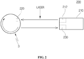
- the second sensor 200 includes a main body 210 having a light emitting part 212 which irradiates the shaft 3 with laser, a reflector 220 which rotates together with the shaft 3 and reflects the laser emitted from the light emitting part 212 to the main body 210, and a light receiving part 230 which is provided in the main body 210 and receives the laser reflected from the reflector 220.
- both of the light emitting part 212 and the light receiving part 230 are provided in the main body 210, and the reflector 220 is located so as to face the main body 210.
- the light emitting part 212 emits laser or straight light, and the laser reflected by the reflector 200 is detected by the light receiving part 230 whenever the reflector 220 rotates once together with the shaft 3.
- the second sensor 200 detects a pulse signal over time whenever the shaft 3 rotates once, and the pulse signal is periodically indicated in the form of bar graph, as illustrated in the drawing, when the shaft 3 is normal.
- the control unit 300 receives signals detected by the first and second sensors 100 and 200 and determines the operation state of the rotor 2. When an aperiodic pulse signal is detected from the rotor 2, the control unit 300 determines the position of the rotor 2 in which the aperiodic pulse signal is generated.
- the control unit 300 determines whether the vibration detected by the first sensor 100 has periodicity by analyzing data signals detected over time. When the rpm of the shaft 3 is uniformly maintained, the periodicity of vibration is uniformly maintained. In this case, the control unit 300 determines whether the signal detected in response to the rotation of the shaft 3 is a periodic signal or an aperiodic signal.
- the pulse signal in the form of bar graph is periodically maintained when the shaft 3 is normal.
- the control unit 300 determines whether or not the current operation of the rotor 2 is abnormal by combining signals detected by the first and second sensors 100 and 200. When signals are uniformly input to the control unit 300 from the first and second sensors 100 and 200, the control unit 300 determines that the current state of the rotor 2 is normal.
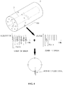
- the vibration signal detected by the combination of the first and second sensors 100 and 200 has an aperiodic pulse at a specific position.
- control unit 300 determines the portion of the rotor 2 in which an aperiodic pulse signal is generated by analyzing the generation position and time of the aperiodic pulse signal, in order to determine the exact position of the rotor 2 in which the aperiodic pulse signal is generated.
- the position of the shaft 3 in which the aperiodic pulse signal is generated is determined by converting the time corresponding to the position into an angle of 360° and calculating the same.
- the current aperiodic pulse signal is positioned at the middle between periodic pulse signals, in which case the distance between the periodic pulse signals corresponds to a time for which the shaft 3 rotates once. Therefore, when the time is converted into an angle of 360°, it is determined that the aperiodic pulse signal is generated at a position of the shaft 3 corresponding to an angle of about 180°.
- the display unit 400 is operated to display the position of the rotor 2 in which an aperiodic pulse signal is generated, based on the information calculated by the control unit 300.
- the display unit 400 of the embodiment may be configured of a plurality of light emitting devices which are circumferentially arranged at regular intervals on the outer periphery of the front end of the rotor 2.
- the display unit 400 is preferably located at the front end of the rotor 2 in order for the operator to easily check the display unit 400 with the naked eye. When it is difficult to install the display unit 400 at the above position, the display unit 400 may be installed at another position.
- the operator may easily check that abnormal vibration occurs at a current position.
- Each of the light emitting devices may be selectively one of a lamp and an LED, but the present disclosure is not limited thereto.
- the display unit 400 may be configured of a plurality of light emitting devices which are axially arranged at regular intervals on the outer periphery of the rotor 2. In this case, when the aperiodic pulse signal is generated at a specific position in the axial direction of the shaft 3, the operator may rapidly and exactly check and inspect the occurrence position of abnormal vibration.
- the control unit 300 may classify an aperiodic pulse signal into three categories, such as safety, inspection, and danger, or more through the leveling of the aperiodic pulse signal, and the operator may recognize these categories.
- the display unit 400 may display the position of the rotor such that colors are changed depending on the respective states of the rotor.
- the light emitting device is lit green when the rotor is in a normal state, and the light emitting device is lit red when the rotor is in an abnormal state.
- the operator or the manager may exactly and visually recognize the current state of the rotor.
- the display unit 400 may be disposed in the state in which the shaft 3 is illustrated in the drawing when the rotor is viewed from the top.
- the display unit 400 may be installed in the front or rear end of the shaft 3 in the axial direction thereof.
- the display unit 400 may be installed in the middle of the shaft 3 in the axial direction thereof.
- the operator or manager may exactly check the position.
- the above-mentioned LED may be used as the display unit 400, and a display window 402 may be separately provided in order to display a current time, an interval, and an intensity in which the aperiodic pulse signal is generated. Since the generation time of the aperiodic pulse signal is displayed on the display window 402, the operator may identify an exact time.
- the operator may exactly determine the current state of the rotor 2 through information on vibration of the rotor 2 when data is accumulated.
- the method of diagnosing abnormal operation of a rotor includes a step (ST100) of detecting vibration occurring in a rotor having a shaft, a vibration state determination step (ST200) of determining whether the detected vibration occurs in a normal state or in an abnormal state, a step (ST300) of, when the vibration occurring in the rotor is determined to be abnormal vibration in the abnormal state, determining a position at which the abnormal vibration occurs, and a step (ST400) of displaying the occurrence position of the abnormal vibration.
- the step (ST100) simultaneously detects periodic vibration which repeatedly occurs while the shaft provided in the rotor rotates once, and aeperiodic vibration which non-repetitively occurs while the shaft rotates once.
- a control unit receives signals detected by first and second sensors which are installed to detect the vibration of the rotor.
- the first sensor is a vibration sensor
- the second sensor is a tachometer sensor.
- the aperiodic vibration may occur once or many times while the shaft rotates once, but is not limited to the number of times.
- the aperiodic vibration irregularly occurs unlike the periodic vibration which normally occurs, the aperiodic vibration is determined together with the periodic vibration.
- step ST200 whether the detected vibration occurs in a normal state or in an abnormal state is determined. For example, when vibration periodically occurs while the shaft axially rotates, the vibration is determined to occur in a normal state (ST220). When vibration aperiodically occurs while the shaft axially rotates, the vibration is determined to occur in an abnormal state (ST210).
- the vibration When the vibration occurs in the normal state (ST220), the vibration involves periodicity according to the rotation of the shaft.
- the vibration occurs in the abnormal state (ST210), the vibration aperiodically occurs at a position, in which the abnormality of the rotor occurs, while involving periodicity according to the rotation of the shaft. Therefore, the vibration state is determined based on the above information.
- the aperiodic vibration may occur in many positions rather than one position. In this case, the operator may rapidly determine whether or not to operate the rotor, thereby preventing an expensive rotor from being damaged.
- the determination of periodic and aperiodic vibration may be subdivided in various modes. For example, when the periodic vibration is detected once or many times, the periodic vibration is not repetitively detected. Therefore, the periodic vibration may be determined to be aperiodic noise.
- the vibration state determination step when vibration periodically occurs once or many times, but is not periodically repeated while the shaft axially rotates, the vibration is determined to occur in a normal state.
- the vibration may be determined to originate from the rotation of the shaft, or from an external source outside of the rotor. For example, since the operation of the rotor is not affected by the vibration which is aperiodically transferred from an external source, it may be determined that the vibration is irrelevant to whether or not vibration occurs in the rotor.
- the noise is determined to be normal noise.
- the position of the rotor in which abnormal vibration occurs is determined by converting a time, at which the aperiodic vibration signal detected between periodic vibration signals generated over time while the shaft rotates is generated, into an angle (ST310).
- the angle of rotation of the shaft over time is calculated by converting the time into an angle of 360°.
- the angle of rotation of the shaft when the time is 0.1S differs from the angle of rotation of the shaft when the time is 0.8S. Accordingly, when an angle is calculated over each time, it is possible to easily determine the position of the shaft in which the aperiodic vibration signal is generated at a specific angle.
- the occurrence position of abnormal vibration when the rotor has a cylindrical shape that extends by a predetermined length in the axial direction of the shaft, the occurrence position of abnormal vibration may be displayed by turning on one light emitting device, corresponding to the occurrence position of aperiodic vibration, among a plurality of light emitting devices which are circumferentially arranged at regular intervals on the front end of the rotor.
- the light emitting device located at the position of the shaft in which abnormal vibration occurs is turned on by calculating an angle over time.
- the operator may exactly check the above position with the naked eye, and thus it is possible to improve accuracy.
- the operator may inspect the rotor by exactly establishing a maintenance management plan before the state of the rotor is deteriorated. In this case, it is possible to previously establish the exact stop period of the rotor, and to stably operate an expensive rotor.
- the exemplary embodiments of the present disclosure can exactly distinguish and check periodic vibration signals and aperiodic vibration signals depending on the rotation of a shaft included in a rotor. Thus, it is possible to prevent damage to the rotor and exactly predict the inspection period thereof.
- the exemplary embodiments of the present disclosure can determine whether or not the shaft is operated in a normal state by a simple configuration without using expensive devices. Thus, it is possible to improve an operator's efficiency.
Landscapes
- Physics & Mathematics (AREA)
- General Physics & Mathematics (AREA)
- Acoustics & Sound (AREA)
- Engineering & Computer Science (AREA)
- Testing Of Devices, Machine Parts, Or Other Structures Thereof (AREA)
- Measurement Of Mechanical Vibrations Or Ultrasonic Waves (AREA)
- Life Sciences & Earth Sciences (AREA)
- Sustainable Development (AREA)
- Sustainable Energy (AREA)
- Chemical & Material Sciences (AREA)
- Combustion & Propulsion (AREA)
- Mechanical Engineering (AREA)
- General Engineering & Computer Science (AREA)
- Power Engineering (AREA)
- Microelectronics & Electronic Packaging (AREA)
Abstract
Description
- Exemplary embodiments of the present disclosure relate to an apparatus and method for diagnosing abnormal operation of a rotor, capable of exactly determining the inspection period of a shaft, which rotates at a specific speed for a long time, as in a rotor or a generator using the rotor having the shaft.
- In general, a wind power generator or a generator is provided therein with a shaft which rotates at a predetermined speed, and the shaft rotates for a long time in the state in which it engages with power transmission components, such as gears for transmitting torque, rather than a single component.
- When the shaft rotates for a long time, the shaft may crack due to stress concentrated on any axial position thereof, or the shaft may collide with another part due to contact with a casing disposed therearound.
- Conventionally, in order to diagnose the state of the shaft used as described above, an operator primarily checks the current state of the shaft with the naked eye, and then inspect portions, which are not checked with the naked eye, using an endoscope.
- If the current state of the shaft is not checked with the naked eye and using the endoscope, the operator should disassemble the shaft in order to check whether the shaft is in a normal or abnormal state through experience.
- In this case, the generator may be not driven for a period of time required to check the shaft by the operator. If the operator does not check the exact defect position of the shaft, the shaft must be diagnosed and analyzed using expensive devices.
- For example, vibration having a certain period typically occurs when the shaft rotates. However, when vibration having an unspecified period instead of a certain period occurs, it is difficult to exactly check the defect position of the shaft.
- An object of the present disclosure is to provide an apparatus and method for diagnosing abnormal operation of a rotor, capable of exactly checking the position of a rotor having a shaft, in which abnormal vibration having aperiodicity occurs. Another object of the present disclosure is to predict an exact inspection period through the same.
- Other objects and advantages of the present disclosure can be understood by the following description, and become apparent with reference to the embodiments of the present invention.
- In accordance with one aspect of the present disclosure, an apparatus for diagnosing abnormal operation of a rotor includes a first sensor provided around a shaft in order to detect vibration occurring while the shaft provided in a rotor axially rotates, a second sensor to generate a periodic pulse signal over time whenever the shaft rotates once, a control unit to determine an operation state of the rotor by receiving signals detected by the first and second sensors, when an aperiodic pulse signal is detected in the rotor, the control unit determining a position of the rotor in which the aperiodic pulse signal is generated, and a display unit to display the position of the rotor in which the aperiodic pulse signal is generated, according to information calculated by the control unit.
- The first sensor may be a vibration sensor, and the second sensor may be a tachometer sensor.
- The first sensor may be located at a bearing mount supporting the shaft.
- The second sensor may include a main body having a light emitting part to irradiate the shaft with laser, a reflector rotating together with the shaft and reflecting the laser emitted from the light emitting part to the main body, and a light receiving part provided in the main body and receiving the laser reflected from the reflector.
- The second sensor may be selectively installed at one of a position facing the first sensor and a position spaced apart from the first sensor by a predetermined angle.
- The display unit may be configured of a plurality of light emitting devices circumferentially arranged at regular intervals on an outer periphery of the rotor.
- The display unit may be configured of a plurality of light emitting devices axially arranged at regular intervals on an outer periphery of the rotor.
- A time, an interval, and an intensity, in which the aperiodic pulse signal is generated, may be displayed on the display unit.
- In accordance with another aspect of the present disclosure, a method of diagnosing abnormal operation of a rotor includes detecting vibration occurring in a rotor having a shaft, determining whether the detected vibration occurs in a normal state or in an abnormal state, when the vibration occurring in the rotor is determined to be abnormal vibration in the abnormal state, determining a position at which the abnormal vibration occurs, and displaying the occurrence position of the abnormal vibration.
- In the detecting vibration, periodic vibration, which repeatedly occurs while the shaft provided in the rotor rotates once, and aeperiodic vibration, which non-repetitively occurs while the shaft provided in the rotor rotates once, may be simultaneously detected.
- In the determining whether the detected vibration occurs, when vibration periodically occurs while the shaft axially rotates, the vibration may be determined to occur in the normal state, and when vibration aperiodically occurs while the shaft axially rotates, the vibration may be determined to occur in the abnormal state.
- In the determining whether the detected vibration occurs, when vibration periodically occurs once or many times, and is then not periodically repeated while the shaft axially rotates, the vibration may be determined to occur in the normal state.
- In the determining whether the detected vibration occurs, the vibration may be determined whether to occur depending on rotation of the shaft or to be transferred to the rotor from the outside.
- In the determining a position at which the abnormal vibration occurs, the position of the rotor in which the abnormal vibration occurs may be determined by converting a time, at which an aperiodic vibration signal detected between periodic vibration signals generated over time while the shaft rotates is generated, into an angle.
- In the displaying the occurrence position of the abnormal vibration, when the rotor has a cylindrical shape that extends by a predetermined length in an axial direction of the shaft, the position of the rotor in which the abnormal vibration occurs may be displayed by turning on one light emitting device, corresponding to an occurrence position of aperiodic vibration, among a plurality of light emitting devices circumferentially arranged at regular intervals on a front end of the rotor.
- It is to be understood that both the foregoing general description and the following detailed description are exemplary and explanatory and are intended to provide further explanation of the exemplary embodiments.
- The above and other objects, features and other advantages of the present disclosure will be more clearly understood from the following detailed description taken in conjunction with the accompanying drawings, in which:
-
Fig. 1 is a view illustrating an apparatus for diagnosing abnormal operation of a rotor according to an exemplary embodiment of the present disclosure; -
Fig. 2 is a view illustrating a vibration sensor, a tachometer sensor, and a combination thereof included in the apparatus for diagnosing abnormal operation of a rotor according to an exemplary embodiment of the present disclosure; -
Fig. 3 is a view illustrating a second sensor included in the apparatus for diagnosing abnormal operation of a rotor according to an exemplary embodiment of the present disclosure; -
Fig. 4 is a view illustrating a state in which abnormal vibration occurs in the apparatus for diagnosing abnormal operation of a rotor according to an exemplary embodiment of the present disclosure; -
Fig. 5 is a view schematically illustrating an installation position of a display unit according to an exemplary embodiment of the present disclosure; and -
Fig. 6 is a flowchart illustrating a method of diagnosing abnormal operation of a rotor according to another exemplary embodiment of the present disclosure. - Exemplary embodiments of the present disclosure will be described below in more detail with reference to the accompanying drawings. The exemplary embodiments may have different forms and should not be construed as limited to the embodiments set forth herein. Rather, these exemplary embodiments are provided so that this disclosure will be thorough and complete, and will fully convey the scope of the present disclosure to those skilled in the art. Throughout the disclosure, like reference numerals refer to like parts throughout the various figures and embodiments of the present disclosure.
- An apparatus for diagnosing abnormal operation of a rotor according to an exemplary embodiment of the present disclosure is characterized in that, in a wind power generator or a generator, which includes a rotor and a shaft and generates power by rotating the shaft, an operator checks and inspects an exact vibration occurrence position with the naked eye after detecting an impact due to vibration caused by the deformation or crack of the shaft at an unspecified position in the axial direction thereof.
- As illustrated in
Figs. 1 to 3 , one embodiment is configured such that first andsecond sensors rotor 2, and the signals detected by the first andsecond sensors control unit 300 so as to be visually and recognizably displayed through adisplay unit 400. - The
first sensor 100 is installed around ashaft 3 in order to detect vibration occurring while theshaft 3 provided in therotor 2 axially rotates. By way of example, thefirst sensor 100 is a vibration sensor, and is located at a bearing mount (not shown) which supports theshaft 3. - The vibration sensor is used to detect vibration occurring while the
shaft 3 axially rotates, and is located outside theshaft 3 so as not to interfere with the rotation of theshaft 3. - The vibration signal detected by the vibration sensor is indicative of an acceleration (Y-axis) over time (X-axis). As illustrated in the drawing, it can be seen that the acceleration is periodically repeated on a cycle over time. That is, the cycle and periodicity of vibration are regularly repeated over time.
- The
second sensor 200 is a tachometer sensor which generates a periodic pulse signal over time whenever theshaft 3 rotates once. The tachometer sensor may be installed at a position, which faces thefirst sensor 100 or is spaced apart from thefirst sensor 100 by a predetermined angle. - For reference, the
second sensor 200 is illustrated to be installed at a position which is spaced apart from thefirst sensor 100 by a predetermined angle in the embodiment. In this case, since an angle of inclination corresponding to the predetermined angle is calibrated by thecontrol unit 300, a pulse signal in response to one rotation of theshaft 3 may be detected with no error. - As shown in
Figure 2 , thesecond sensor 200 includes amain body 210 having alight emitting part 212 which irradiates theshaft 3 with laser, areflector 220 which rotates together with theshaft 3 and reflects the laser emitted from thelight emitting part 212 to themain body 210, and alight receiving part 230 which is provided in themain body 210 and receives the laser reflected from thereflector 220. - In the
second sensor 200, both of thelight emitting part 212 and thelight receiving part 230 are provided in themain body 210, and thereflector 220 is located so as to face themain body 210. - The
light emitting part 212 emits laser or straight light, and the laser reflected by thereflector 200 is detected by thelight receiving part 230 whenever thereflector 220 rotates once together with theshaft 3. - Accordingly, the
second sensor 200 detects a pulse signal over time whenever theshaft 3 rotates once, and the pulse signal is periodically indicated in the form of bar graph, as illustrated in the drawing, when theshaft 3 is normal. - The
control unit 300 receives signals detected by the first andsecond sensors rotor 2. When an aperiodic pulse signal is detected from therotor 2, thecontrol unit 300 determines the position of therotor 2 in which the aperiodic pulse signal is generated. - The
control unit 300 determines whether the vibration detected by thefirst sensor 100 has periodicity by analyzing data signals detected over time. When the rpm of theshaft 3 is uniformly maintained, the periodicity of vibration is uniformly maintained. In this case, thecontrol unit 300 determines whether the signal detected in response to the rotation of theshaft 3 is a periodic signal or an aperiodic signal. - Unlike the
first sensor 100, since the laser emitted from thelight emitting part 212 is reflected by thereflector 220 and is then received in thelight receiving part 230 in thesecond sensor 200, the pulse signal in the form of bar graph is periodically maintained when theshaft 3 is normal. - The
control unit 300 determines whether or not the current operation of therotor 2 is abnormal by combining signals detected by the first andsecond sensors control unit 300 from the first andsecond sensors control unit 300 determines that the current state of therotor 2 is normal. - Referring to
Figs. 4 and5 , if theshaft 3 cracks or collides with a casing surrounding theshaft 3, the vibration signal detected by the combination of the first andsecond sensors - In this case, the
control unit 300 determines the portion of therotor 2 in which an aperiodic pulse signal is generated by analyzing the generation position and time of the aperiodic pulse signal, in order to determine the exact position of therotor 2 in which the aperiodic pulse signal is generated. - For example, since the periodic pulse signal detected by the
second sensor 200 is generated whenever theshaft 3 rotates once, an aperiodic pulse signal is generated between the periodic pulse signals. Therefore, the position of theshaft 3 in which the aperiodic pulse signal is generated is determined by converting the time corresponding to the position into an angle of 360° and calculating the same. - That is, the current aperiodic pulse signal is positioned at the middle between periodic pulse signals, in which case the distance between the periodic pulse signals corresponds to a time for which the
shaft 3 rotates once. Therefore, when the time is converted into an angle of 360°, it is determined that the aperiodic pulse signal is generated at a position of theshaft 3 corresponding to an angle of about 180°. - The
display unit 400 is operated to display the position of therotor 2 in which an aperiodic pulse signal is generated, based on the information calculated by thecontrol unit 300. By way of example, thedisplay unit 400 of the embodiment may be configured of a plurality of light emitting devices which are circumferentially arranged at regular intervals on the outer periphery of the front end of therotor 2. - The
display unit 400 is preferably located at the front end of therotor 2 in order for the operator to easily check thedisplay unit 400 with the naked eye. When it is difficult to install thedisplay unit 400 at the above position, thedisplay unit 400 may be installed at another position. - In this embodiment, when the light emitting device, which is located at a position of the shaft corresponding to an angle of about 180° in which the aperiodic pulse signal is generated, is turned on, the operator may easily check that abnormal vibration occurs at a current position.
- Each of the light emitting devices may be selectively one of a lamp and an LED, but the present disclosure is not limited thereto.
- The
display unit 400 may be configured of a plurality of light emitting devices which are axially arranged at regular intervals on the outer periphery of therotor 2. In this case, when the aperiodic pulse signal is generated at a specific position in the axial direction of theshaft 3, the operator may rapidly and exactly check and inspect the occurrence position of abnormal vibration. - The
control unit 300 may classify an aperiodic pulse signal into three categories, such as safety, inspection, and danger, or more through the leveling of the aperiodic pulse signal, and the operator may recognize these categories. In this case, thedisplay unit 400 may display the position of the rotor such that colors are changed depending on the respective states of the rotor. - For example, in one embodiment, the light emitting device is lit green when the rotor is in a normal state, and the light emitting device is lit red when the rotor is in an abnormal state. Thus, the operator or the manager may exactly and visually recognize the current state of the rotor.
- In addition, when the leveling is in a dangerous state, it is possible to sound a warning by operating a separate alarm (not shown). Through such a configuration, it is possible to warn the operator of the current state of the rotor, and to cope with a dangerous state.
- Referring to
Fig. 5 , thedisplay unit 400 may be disposed in the state in which theshaft 3 is illustrated in the drawing when the rotor is viewed from the top. In this case, thedisplay unit 400 may be installed in the front or rear end of theshaft 3 in the axial direction thereof. Alternatively, thedisplay unit 400 may be installed in the middle of theshaft 3 in the axial direction thereof. - When abnormal vibration occurs at a specific position in the axial direction of the
shaft 3, the operator or manager may exactly check the position. - The above-mentioned LED may be used as the
display unit 400, and adisplay window 402 may be separately provided in order to display a current time, an interval, and an intensity in which the aperiodic pulse signal is generated. Since the generation time of the aperiodic pulse signal is displayed on thedisplay window 402, the operator may identify an exact time. - In addition, since the interval and intensity of the aperiodic pulse signal are displayed on the
display window 402, the operator may exactly determine the current state of therotor 2 through information on vibration of therotor 2 when data is accumulated. - Hereinafter, a method of diagnosing abnormal operation of a rotor according to another embodiment of the present disclosure will be described with reference to the drawing.
- Referring to
Fig. 6 , the method of diagnosing abnormal operation of a rotor according to an exemplary embodiment of the present disclosure includes a step (ST100) of detecting vibration occurring in a rotor having a shaft, a vibration state determination step (ST200) of determining whether the detected vibration occurs in a normal state or in an abnormal state, a step (ST300) of, when the vibration occurring in the rotor is determined to be abnormal vibration in the abnormal state, determining a position at which the abnormal vibration occurs, and a step (ST400) of displaying the occurrence position of the abnormal vibration. - The step (ST100) simultaneously detects periodic vibration which repeatedly occurs while the shaft provided in the rotor rotates once, and aeperiodic vibration which non-repetitively occurs while the shaft rotates once. In this case, a control unit receives signals detected by first and second sensors which are installed to detect the vibration of the rotor.
- The first sensor is a vibration sensor, and the second sensor is a tachometer sensor. Thus, the periodicity of vibration occurring whenever the shaft rotates once is detected by the vibration sensor, and a pulse signal having a specific period, which is generated whenever the shaft rotates once, is detected by the tachometer sensor. As a result, the current vibration of the rotor is detected in real time.
- Here, the aperiodic vibration may occur once or many times while the shaft rotates once, but is not limited to the number of times. In particular, since the aperiodic vibration irregularly occurs unlike the periodic vibration which normally occurs, the aperiodic vibration is determined together with the periodic vibration.
- In step ST200, whether the detected vibration occurs in a normal state or in an abnormal state is determined. For example, when vibration periodically occurs while the shaft axially rotates, the vibration is determined to occur in a normal state (ST220). When vibration aperiodically occurs while the shaft axially rotates, the vibration is determined to occur in an abnormal state (ST210).
- When the vibration occurs in the normal state (ST220), the vibration involves periodicity according to the rotation of the shaft. When the vibration occurs in the abnormal state (ST210), the vibration aperiodically occurs at a position, in which the abnormality of the rotor occurs, while involving periodicity according to the rotation of the shaft. Therefore, the vibration state is determined based on the above information.
- If a plurality of cracks occur in the shaft, the aperiodic vibration may occur in many positions rather than one position. In this case, the operator may rapidly determine whether or not to operate the rotor, thereby preventing an expensive rotor from being damaged.
- Particularly, the determination of periodic and aperiodic vibration may be subdivided in various modes. For example, when the periodic vibration is detected once or many times, the periodic vibration is not repetitively detected. Therefore, the periodic vibration may be determined to be aperiodic noise.
- In the vibration state determination step, when vibration periodically occurs once or many times, but is not periodically repeated while the shaft axially rotates, the vibration is determined to occur in a normal state.
- For example, when vibration non-repetitively occurs once or twice, periodicity is not maintained. Therefore, it may be determined that the shaft normally rotates.
- In the vibration state determination step, the vibration may be determined to originate from the rotation of the shaft, or from an external source outside of the rotor. For example, since the operation of the rotor is not affected by the vibration which is aperiodically transferred from an external source, it may be determined that the vibration is irrelevant to whether or not vibration occurs in the rotor.
- In the determination of periodic and aperiodic noise, when particular noise is not additionally detected compared to normal noise occurring depending on the normal rotation of the shaft, the noise is determined to be normal noise.
- In order to determine the occurrence position of abnormal vibration (ST300), the position of the rotor in which abnormal vibration occurs is determined by converting a time, at which the aperiodic vibration signal detected between periodic vibration signals generated over time while the shaft rotates is generated, into an angle (ST310).
- When the shaft rotates at a certain speed, a predetermined time is required whenever the shaft rotates once. Accordingly, the angle of rotation of the shaft over time is calculated by converting the time into an angle of 360°. For example, the angle of rotation of the shaft when the time is 0.1S differs from the angle of rotation of the shaft when the time is 0.8S. Accordingly, when an angle is calculated over each time, it is possible to easily determine the position of the shaft in which the aperiodic vibration signal is generated at a specific angle.
- In order to display the occurrence position of abnormal vibration (ST400), when the rotor has a cylindrical shape that extends by a predetermined length in the axial direction of the shaft, the occurrence position of abnormal vibration may be displayed by turning on one light emitting device, corresponding to the occurrence position of aperiodic vibration, among a plurality of light emitting devices which are circumferentially arranged at regular intervals on the front end of the rotor.
- As described above, the light emitting device located at the position of the shaft in which abnormal vibration occurs is turned on by calculating an angle over time. In this case, the operator may exactly check the above position with the naked eye, and thus it is possible to improve accuracy.
- In this case, the operator may inspect the rotor by exactly establishing a maintenance management plan before the state of the rotor is deteriorated. In this case, it is possible to previously establish the exact stop period of the rotor, and to stably operate an expensive rotor.
- As is apparent from the above description, the exemplary embodiments of the present disclosure can exactly distinguish and check periodic vibration signals and aperiodic vibration signals depending on the rotation of a shaft included in a rotor. Thus, it is possible to prevent damage to the rotor and exactly predict the inspection period thereof.
- The exemplary embodiments of the present disclosure can determine whether or not the shaft is operated in a normal state by a simple configuration without using expensive devices. Thus, it is possible to improve an operator's efficiency.
- When an aperiodic vibration signal is detected at the specific position of the shaft, it is possible to exactly display the above position. Thus, since a time required to detect the occurrence position of vibration is significantly reduced, the operator can immediately cope with the situation after checking the position.
- While the present disclosure has been described with respect to the specific embodiments, it will be apparent to those skilled in the art that various changes and modifications may be made without departing from the spirit and scope of the disclosure as defined in the following claims.
Claims (15)
- An apparatus for diagnosing abnormal operation of a rotor, comprising:a first sensor provided around a shaft in order to detect vibration occurring while the shaft provided in a rotor axially rotates;a second sensor to generate a periodic pulse signal over time whenever the shaft rotates once;a controller configured to determine an operation state of the rotor by receiving signals detected by the first and second sensors, and when an aperiodic pulse signal is detected in the rotor, the controller determines a position of the rotor from which the aperiodic pulse signal is generated; anda display configured to display the position of the rotor in which the aperiodic pulse signal is generated, according to information calculated by the controller.
- The apparatus according to claim 1, wherein the first sensor is a vibration sensor, and the second sensor is a tachometer sensor.
- The apparatus according to claim 1, wherein the first sensor is located at a bearing mount supporting the shaft.
- The apparatus according to claim 2, wherein the second sensor comprises:a main body having a light emitting part to irradiate the shaft with a laser;a reflector rotating together with the shaft and reflecting the laser emitted from the light emitting part back to the main body; anda light receiving part provided on the main body that receives the laser reflected from the reflector.
- The apparatus according to claim 2, wherein the second sensor is selectively installed at one of a position facing the first sensor and a position spaced apart from the first sensor by a predetermined angle.
- The apparatus according to claim 1, wherein the display comprises a plurality of light emitting devices circumferentially arranged at regular intervals on an outer periphery of the rotor.
- The apparatus according to claim 1, wherein the display comprises a plurality of light emitting devices axially arranged at regular intervals on an outer periphery of the rotor.
- The apparatus according to claim 1, wherein a time, an interval, and an intensity in which the aperiodic pulse signal is generated are displayed on the display.
- A method of diagnosing abnormal operation of a rotor, comprising:detecting vibration occurring in a rotor having a shaft;determining whether the detected vibration occurs in a normal state or in an abnormal state;when the vibration occurring in the rotor is determined to be abnormal vibration in the abnormal state, determining a position at which the abnormal vibration occurs; anddisplaying the occurrence position of the abnormal vibration.
- The method according to claim 9, wherein detecting vibration comprises simultaneously detecting periodic vibration, which repeatedly occurs while the shaft provided in the rotor rotates, and aperiodic vibration, which occurs non-repetitively while the shaft provided in the rotor rotates.
- The method according to claim 9, wherein determining whether the detected vibration occurs in a normal state or an abnormal state comprises:determining that the vibration occurs in the normal state when vibration periodically occurs while the shaft axially rotates, anddetermining that the vibration occurs in the abnormal state when vibration aperiodically occurs while the shaft axially rotates.
- The method according to claim 9, wherein determining whether the detected vibration occurs in a normal state or in an abnormal state comprises determining that the vibration occurs in the normal state when vibration periodically occurs once or many times, and is not periodically repeated while the shaft axially rotates.
- The method according to claim 9, wherein determining whether the detected vibration occurs in a normal state or in an abnormal state comprises determining whether the vibration originates from rotation of the shaft, or whether the vibration originates from an external source.
- The method according to claim 9, wherein determining a position at which the abnormal vibration occurs comprises converting a time at which an aperiodic vibration signal is detected between periodic vibration signals generated over time while the shaft rotates into an angle.
- The method according to claim 9, wherein displaying the occurrence position of the abnormal vibration comprises:when the rotor has a cylindrical shape that extends by a predetermined length in an axial direction of the shaft, displaying the position of the rotor at which the abnormal vibration occurs by turning on one light emitting device, corresponding to an occurrence position of aperiodic vibration, among a plurality of light emitting devices circumferentially arranged at regular intervals on a front end of the rotor.
Applications Claiming Priority (1)
| Application Number | Priority Date | Filing Date | Title |
|---|---|---|---|
| KR1020150157608A KR101761022B1 (en) | 2015-11-10 | 2015-11-10 | Abnormal operation diagnosis rotating device |
Publications (2)
| Publication Number | Publication Date |
|---|---|
| EP3168583A1 true EP3168583A1 (en) | 2017-05-17 |
| EP3168583B1 EP3168583B1 (en) | 2021-01-13 |
Family
ID=57281093
Family Applications (1)
| Application Number | Title | Priority Date | Filing Date |
|---|---|---|---|
| EP16197940.6A Active EP3168583B1 (en) | 2015-11-10 | 2016-11-09 | Apparatus and method for diagnosing abnormal operation of a rotor |
Country Status (3)
| Country | Link |
|---|---|
| US (1) | US10481034B2 (en) |
| EP (1) | EP3168583B1 (en) |
| KR (1) | KR101761022B1 (en) |
Cited By (1)
| Publication number | Priority date | Publication date | Assignee | Title |
|---|---|---|---|---|
| CN111664929A (en) * | 2019-03-05 | 2020-09-15 | 计算系统有限公司 | System for separating periodic amplitude peaks and non-periodic amplitude peaks in machine vibration data |
Families Citing this family (9)
| Publication number | Priority date | Publication date | Assignee | Title |
|---|---|---|---|---|
| US11016003B2 (en) | 2016-11-17 | 2021-05-25 | Ez Pulley Llc | Systems and methods for detection and analysis of faulty components in a rotating pulley system |
| KR102060796B1 (en) * | 2017-05-22 | 2020-01-31 | 정경균 | Vertical wind generator |
| CN107643549B (en) * | 2017-10-13 | 2024-03-01 | 国能大渡河流域水电开发有限公司龚嘴水力发电总厂 | Non-contact generator set air gap foreign matter online detection alarm structure and alarm method |
| CN108827539B (en) * | 2018-03-30 | 2020-02-21 | 江苏大学 | A multi-rotor assembly online dynamic balance test device |
| CN109580217B (en) * | 2018-09-27 | 2020-08-14 | 中北大学 | Fault monitoring method for wind power gear box |
| JP2022100163A (en) * | 2020-12-23 | 2022-07-05 | トヨタ自動車株式会社 | Sound source estimation server, sound source estimation system, sound source estimation device, and method for estimating sound source |
| US20220373422A1 (en) * | 2021-05-20 | 2022-11-24 | Machine Saver, Inc. | Vibration detection and correction system |
| US11781782B2 (en) | 2021-06-23 | 2023-10-10 | Carrier Corporation | Indication of motor shaft rotation and controller location |
| KR102619799B1 (en) * | 2021-12-14 | 2024-01-03 | 한국표준과학연구원 | The system and method for D-norm based time-synchronous averaging for diagnosing faults of rotation body |
Citations (3)
| Publication number | Priority date | Publication date | Assignee | Title |
|---|---|---|---|---|
| US4335600A (en) * | 1980-11-13 | 1982-06-22 | General Electric Company | Detecting internal abnormalities in turbines |
| US6098022A (en) * | 1997-10-17 | 2000-08-01 | Test Devices, Inc. | Detecting anomalies in rotating components |
| US20130282335A1 (en) * | 2010-01-15 | 2013-10-24 | Fluke Corporation | User Interface System And Method For Diagnosing A Rotating Machine Condition Not Based Upon Prior Measurement History |
Family Cites Families (6)
| Publication number | Priority date | Publication date | Assignee | Title |
|---|---|---|---|---|
| US2090803A (en) * | 1933-07-13 | 1937-08-24 | Harry W Moore | Dynamic balancing apparatus |
| US4238960A (en) | 1978-11-27 | 1980-12-16 | Lockheed Corporation | Means for balancing rotors of a machine |
| JPS5834363A (en) | 1981-08-25 | 1983-02-28 | Yokogawa Hokushin Electric Corp | Tachometer |
| JPH08334405A (en) | 1995-06-08 | 1996-12-17 | Omron Corp | Abnormality diagnosis device for rotating machines |
| JP2009281839A (en) * | 2008-05-22 | 2009-12-03 | Sanyo Special Steel Co Ltd | Surface flaw inspection method of metal rod material |
| US8042412B2 (en) * | 2008-06-25 | 2011-10-25 | General Electric Company | Turbomachinery system fiberoptic multi-parameter sensing system and method |
-
2015
- 2015-11-10 KR KR1020150157608A patent/KR101761022B1/en active Active
-
2016
- 2016-11-09 EP EP16197940.6A patent/EP3168583B1/en active Active
- 2016-11-10 US US15/348,267 patent/US10481034B2/en active Active
Patent Citations (3)
| Publication number | Priority date | Publication date | Assignee | Title |
|---|---|---|---|---|
| US4335600A (en) * | 1980-11-13 | 1982-06-22 | General Electric Company | Detecting internal abnormalities in turbines |
| US6098022A (en) * | 1997-10-17 | 2000-08-01 | Test Devices, Inc. | Detecting anomalies in rotating components |
| US20130282335A1 (en) * | 2010-01-15 | 2013-10-24 | Fluke Corporation | User Interface System And Method For Diagnosing A Rotating Machine Condition Not Based Upon Prior Measurement History |
Cited By (2)
| Publication number | Priority date | Publication date | Assignee | Title |
|---|---|---|---|---|
| CN111664929A (en) * | 2019-03-05 | 2020-09-15 | 计算系统有限公司 | System for separating periodic amplitude peaks and non-periodic amplitude peaks in machine vibration data |
| CN111664929B (en) * | 2019-03-05 | 2022-05-03 | 计算系统有限公司 | System for separating periodic amplitude peaks and non-periodic amplitude peaks in machine vibration data |
Also Published As
| Publication number | Publication date |
|---|---|
| US20170131172A1 (en) | 2017-05-11 |
| KR101761022B1 (en) | 2017-07-24 |
| EP3168583B1 (en) | 2021-01-13 |
| US10481034B2 (en) | 2019-11-19 |
| KR20170054893A (en) | 2017-05-18 |
Similar Documents
| Publication | Publication Date | Title |
|---|---|---|
| EP3168583B1 (en) | Apparatus and method for diagnosing abnormal operation of a rotor | |
| US9400229B2 (en) | Apparatus and method for monitoring the state of a roller bearing | |
| US7231303B2 (en) | Vibration sensor and method for monitoring the condition of rotating components and bearings | |
| JP2018179735A (en) | Method and apparatus for diagnosing abnormality of rotating parts | |
| CN102607630B (en) | Encoder fault detection method, device and system | |
| CN101473185B (en) | Rotary encoder with built-in self-test | |
| US20120148400A1 (en) | System for detecting an ephemeral event on a vane impeller of an aircraft engine | |
| JP2017219469A (en) | State monitoring device and state monitoring method | |
| CN108861923B (en) | Automatic elevator inspection system and method | |
| KR20170064609A (en) | Failure dignosis method for vehicle | |
| KR102126373B1 (en) | Monitoring method and for detecting the formation of a degradation in at least one moving part of a rotating mechanism and associated system | |
| US20190265097A1 (en) | Method and device for the functional testing of a fibre-optic sensor and computer program product | |
| CN107735679A (en) | For the acoustic apparatus for detecting, positioning and evaluation structure is hit | |
| JP5879214B2 (en) | Abnormality diagnosis method, abnormality diagnosis device, and passenger conveyor equipped with abnormality diagnosis device | |
| JP2022544003A (en) | Elevator rope monitor device, method and computer program product therefor, and elevator system | |
| KR101602143B1 (en) | Crane safety monitoring system | |
| WO2017072172A1 (en) | Sensor-monitored drive engine arrangement for an elevator system | |
| KR20160013682A (en) | Apparatus and method for detecting flaw of tire | |
| US20220074391A1 (en) | Method and system for detecting machine defects | |
| KR100968049B1 (en) | Sensor verification and signal pick-up analyser for speed control and control method thereof | |
| KR101750509B1 (en) | Apparatus for monitoring radar rotating structure using soind camera and method thereof | |
| JP6193938B2 (en) | Rotation angle detector with function to detect foreign material intrusion from frequency characteristics of signal | |
| KR101669401B1 (en) | System for Previous Warning of Test Apparatus | |
| EP4343301A1 (en) | Method for identifying periodic shocks in a structure, wind turbine generator and a wind farm adapted for performing the method | |
| KR200455910Y1 (en) | TDM Signal Processing Apparatus for Vibration Supervisory of Turbine Generator |
Legal Events
| Date | Code | Title | Description |
|---|---|---|---|
| PUAI | Public reference made under article 153(3) epc to a published international application that has entered the european phase |
Free format text: ORIGINAL CODE: 0009012 |
|
| STAA | Information on the status of an ep patent application or granted ep patent |
Free format text: STATUS: THE APPLICATION HAS BEEN PUBLISHED |
|
| AK | Designated contracting states |
Kind code of ref document: A1 Designated state(s): AL AT BE BG CH CY CZ DE DK EE ES FI FR GB GR HR HU IE IS IT LI LT LU LV MC MK MT NL NO PL PT RO RS SE SI SK SM TR |
|
| AX | Request for extension of the european patent |
Extension state: BA ME |
|
| STAA | Information on the status of an ep patent application or granted ep patent |
Free format text: STATUS: REQUEST FOR EXAMINATION WAS MADE |
|
| 17P | Request for examination filed |
Effective date: 20170810 |
|
| RBV | Designated contracting states (corrected) |
Designated state(s): AL AT BE BG CH CY CZ DE DK EE ES FI FR GB GR HR HU IE IS IT LI LT LU LV MC MK MT NL NO PL PT RO RS SE SI SK SM TR |
|
| STAA | Information on the status of an ep patent application or granted ep patent |
Free format text: STATUS: EXAMINATION IS IN PROGRESS |
|
| 17Q | First examination report despatched |
Effective date: 20190709 |
|
| GRAP | Despatch of communication of intention to grant a patent |
Free format text: ORIGINAL CODE: EPIDOSNIGR1 |
|
| STAA | Information on the status of an ep patent application or granted ep patent |
Free format text: STATUS: GRANT OF PATENT IS INTENDED |
|
| RIC1 | Information provided on ipc code assigned before grant |
Ipc: G01H 1/00 20060101AFI20200723BHEP Ipc: G01M 13/028 20190101ALI20200723BHEP |
|
| INTG | Intention to grant announced |
Effective date: 20200813 |
|
| RIN1 | Information on inventor provided before grant (corrected) |
Inventor name: LEE, GANG JU Inventor name: SON, JONG DUK Inventor name: EOM, SEUNG MAN Inventor name: JANG, EUN SUNG |
|
| GRAS | Grant fee paid |
Free format text: ORIGINAL CODE: EPIDOSNIGR3 |
|
| GRAA | (expected) grant |
Free format text: ORIGINAL CODE: 0009210 |
|
| STAA | Information on the status of an ep patent application or granted ep patent |
Free format text: STATUS: THE PATENT HAS BEEN GRANTED |
|
| AK | Designated contracting states |
Kind code of ref document: B1 Designated state(s): AL AT BE BG CH CY CZ DE DK EE ES FI FR GB GR HR HU IE IS IT LI LT LU LV MC MK MT NL NO PL PT RO RS SE SI SK SM TR |
|
| REG | Reference to a national code |
Ref country code: GB Ref legal event code: FG4D |
|
| REG | Reference to a national code |
Ref country code: CH Ref legal event code: EP |
|
| REG | Reference to a national code |
Ref country code: DE Ref legal event code: R096 Ref document number: 602016051328 Country of ref document: DE |
|
| REG | Reference to a national code |
Ref country code: IE Ref legal event code: FG4D |
|
| REG | Reference to a national code |
Ref country code: AT Ref legal event code: REF Ref document number: 1354922 Country of ref document: AT Kind code of ref document: T Effective date: 20210215 |
|
| REG | Reference to a national code |
Ref country code: AT Ref legal event code: MK05 Ref document number: 1354922 Country of ref document: AT Kind code of ref document: T Effective date: 20210113 |
|
| REG | Reference to a national code |
Ref country code: NL Ref legal event code: MP Effective date: 20210113 |
|
| REG | Reference to a national code |
Ref country code: LT Ref legal event code: MG9D |
|
| PG25 | Lapsed in a contracting state [announced via postgrant information from national office to epo] |
Ref country code: LT Free format text: LAPSE BECAUSE OF FAILURE TO SUBMIT A TRANSLATION OF THE DESCRIPTION OR TO PAY THE FEE WITHIN THE PRESCRIBED TIME-LIMIT Effective date: 20210113 Ref country code: NL Free format text: LAPSE BECAUSE OF FAILURE TO SUBMIT A TRANSLATION OF THE DESCRIPTION OR TO PAY THE FEE WITHIN THE PRESCRIBED TIME-LIMIT Effective date: 20210113 Ref country code: BG Free format text: LAPSE BECAUSE OF FAILURE TO SUBMIT A TRANSLATION OF THE DESCRIPTION OR TO PAY THE FEE WITHIN THE PRESCRIBED TIME-LIMIT Effective date: 20210413 Ref country code: HR Free format text: LAPSE BECAUSE OF FAILURE TO SUBMIT A TRANSLATION OF THE DESCRIPTION OR TO PAY THE FEE WITHIN THE PRESCRIBED TIME-LIMIT Effective date: 20210113 Ref country code: GR Free format text: LAPSE BECAUSE OF FAILURE TO SUBMIT A TRANSLATION OF THE DESCRIPTION OR TO PAY THE FEE WITHIN THE PRESCRIBED TIME-LIMIT Effective date: 20210414 Ref country code: FI Free format text: LAPSE BECAUSE OF FAILURE TO SUBMIT A TRANSLATION OF THE DESCRIPTION OR TO PAY THE FEE WITHIN THE PRESCRIBED TIME-LIMIT Effective date: 20210113 Ref country code: NO Free format text: LAPSE BECAUSE OF FAILURE TO SUBMIT A TRANSLATION OF THE DESCRIPTION OR TO PAY THE FEE WITHIN THE PRESCRIBED TIME-LIMIT Effective date: 20210413 Ref country code: PT Free format text: LAPSE BECAUSE OF FAILURE TO SUBMIT A TRANSLATION OF THE DESCRIPTION OR TO PAY THE FEE WITHIN THE PRESCRIBED TIME-LIMIT Effective date: 20210513 |
|
| PG25 | Lapsed in a contracting state [announced via postgrant information from national office to epo] |
Ref country code: SE Free format text: LAPSE BECAUSE OF FAILURE TO SUBMIT A TRANSLATION OF THE DESCRIPTION OR TO PAY THE FEE WITHIN THE PRESCRIBED TIME-LIMIT Effective date: 20210113 Ref country code: AT Free format text: LAPSE BECAUSE OF FAILURE TO SUBMIT A TRANSLATION OF THE DESCRIPTION OR TO PAY THE FEE WITHIN THE PRESCRIBED TIME-LIMIT Effective date: 20210113 Ref country code: LV Free format text: LAPSE BECAUSE OF FAILURE TO SUBMIT A TRANSLATION OF THE DESCRIPTION OR TO PAY THE FEE WITHIN THE PRESCRIBED TIME-LIMIT Effective date: 20210113 Ref country code: PL Free format text: LAPSE BECAUSE OF FAILURE TO SUBMIT A TRANSLATION OF THE DESCRIPTION OR TO PAY THE FEE WITHIN THE PRESCRIBED TIME-LIMIT Effective date: 20210113 Ref country code: RS Free format text: LAPSE BECAUSE OF FAILURE TO SUBMIT A TRANSLATION OF THE DESCRIPTION OR TO PAY THE FEE WITHIN THE PRESCRIBED TIME-LIMIT Effective date: 20210113 |
|
| PG25 | Lapsed in a contracting state [announced via postgrant information from national office to epo] |
Ref country code: IS Free format text: LAPSE BECAUSE OF FAILURE TO SUBMIT A TRANSLATION OF THE DESCRIPTION OR TO PAY THE FEE WITHIN THE PRESCRIBED TIME-LIMIT Effective date: 20210513 |
|
| REG | Reference to a national code |
Ref country code: DE Ref legal event code: R097 Ref document number: 602016051328 Country of ref document: DE |
|
| PG25 | Lapsed in a contracting state [announced via postgrant information from national office to epo] |
Ref country code: EE Free format text: LAPSE BECAUSE OF FAILURE TO SUBMIT A TRANSLATION OF THE DESCRIPTION OR TO PAY THE FEE WITHIN THE PRESCRIBED TIME-LIMIT Effective date: 20210113 Ref country code: CZ Free format text: LAPSE BECAUSE OF FAILURE TO SUBMIT A TRANSLATION OF THE DESCRIPTION OR TO PAY THE FEE WITHIN THE PRESCRIBED TIME-LIMIT Effective date: 20210113 Ref country code: SM Free format text: LAPSE BECAUSE OF FAILURE TO SUBMIT A TRANSLATION OF THE DESCRIPTION OR TO PAY THE FEE WITHIN THE PRESCRIBED TIME-LIMIT Effective date: 20210113 |
|
| PLBE | No opposition filed within time limit |
Free format text: ORIGINAL CODE: 0009261 |
|
| STAA | Information on the status of an ep patent application or granted ep patent |
Free format text: STATUS: NO OPPOSITION FILED WITHIN TIME LIMIT |
|
| PG25 | Lapsed in a contracting state [announced via postgrant information from national office to epo] |
Ref country code: DK Free format text: LAPSE BECAUSE OF FAILURE TO SUBMIT A TRANSLATION OF THE DESCRIPTION OR TO PAY THE FEE WITHIN THE PRESCRIBED TIME-LIMIT Effective date: 20210113 Ref country code: ES Free format text: LAPSE BECAUSE OF FAILURE TO SUBMIT A TRANSLATION OF THE DESCRIPTION OR TO PAY THE FEE WITHIN THE PRESCRIBED TIME-LIMIT Effective date: 20210113 Ref country code: SK Free format text: LAPSE BECAUSE OF FAILURE TO SUBMIT A TRANSLATION OF THE DESCRIPTION OR TO PAY THE FEE WITHIN THE PRESCRIBED TIME-LIMIT Effective date: 20210113 Ref country code: RO Free format text: LAPSE BECAUSE OF FAILURE TO SUBMIT A TRANSLATION OF THE DESCRIPTION OR TO PAY THE FEE WITHIN THE PRESCRIBED TIME-LIMIT Effective date: 20210113 |
|
| 26N | No opposition filed |
Effective date: 20211014 |
|
| PG25 | Lapsed in a contracting state [announced via postgrant information from national office to epo] |
Ref country code: AL Free format text: LAPSE BECAUSE OF FAILURE TO SUBMIT A TRANSLATION OF THE DESCRIPTION OR TO PAY THE FEE WITHIN THE PRESCRIBED TIME-LIMIT Effective date: 20210113 |
|
| PG25 | Lapsed in a contracting state [announced via postgrant information from national office to epo] |
Ref country code: SI Free format text: LAPSE BECAUSE OF FAILURE TO SUBMIT A TRANSLATION OF THE DESCRIPTION OR TO PAY THE FEE WITHIN THE PRESCRIBED TIME-LIMIT Effective date: 20210113 |
|
| PG25 | Lapsed in a contracting state [announced via postgrant information from national office to epo] |
Ref country code: IT Free format text: LAPSE BECAUSE OF FAILURE TO SUBMIT A TRANSLATION OF THE DESCRIPTION OR TO PAY THE FEE WITHIN THE PRESCRIBED TIME-LIMIT Effective date: 20210113 |
|
| PG25 | Lapsed in a contracting state [announced via postgrant information from national office to epo] |
Ref country code: IS Free format text: LAPSE BECAUSE OF FAILURE TO SUBMIT A TRANSLATION OF THE DESCRIPTION OR TO PAY THE FEE WITHIN THE PRESCRIBED TIME-LIMIT Effective date: 20210513 |
|
| PG25 | Lapsed in a contracting state [announced via postgrant information from national office to epo] |
Ref country code: MC Free format text: LAPSE BECAUSE OF FAILURE TO SUBMIT A TRANSLATION OF THE DESCRIPTION OR TO PAY THE FEE WITHIN THE PRESCRIBED TIME-LIMIT Effective date: 20210113 |
|
| REG | Reference to a national code |
Ref country code: CH Ref legal event code: PL |
|
| PG25 | Lapsed in a contracting state [announced via postgrant information from national office to epo] |
Ref country code: LU Free format text: LAPSE BECAUSE OF NON-PAYMENT OF DUE FEES Effective date: 20211109 Ref country code: BE Free format text: LAPSE BECAUSE OF NON-PAYMENT OF DUE FEES Effective date: 20211130 |
|
| REG | Reference to a national code |
Ref country code: BE Ref legal event code: MM Effective date: 20211130 |
|
| PG25 | Lapsed in a contracting state [announced via postgrant information from national office to epo] |
Ref country code: LI Free format text: LAPSE BECAUSE OF NON-PAYMENT OF DUE FEES Effective date: 20211130 Ref country code: CH Free format text: LAPSE BECAUSE OF NON-PAYMENT OF DUE FEES Effective date: 20211130 |
|
| PG25 | Lapsed in a contracting state [announced via postgrant information from national office to epo] |
Ref country code: IE Free format text: LAPSE BECAUSE OF NON-PAYMENT OF DUE FEES Effective date: 20211109 |
|
| PG25 | Lapsed in a contracting state [announced via postgrant information from national office to epo] |
Ref country code: FR Free format text: LAPSE BECAUSE OF NON-PAYMENT OF DUE FEES Effective date: 20211130 |
|
| PG25 | Lapsed in a contracting state [announced via postgrant information from national office to epo] |
Ref country code: HU Free format text: LAPSE BECAUSE OF FAILURE TO SUBMIT A TRANSLATION OF THE DESCRIPTION OR TO PAY THE FEE WITHIN THE PRESCRIBED TIME-LIMIT; INVALID AB INITIO Effective date: 20161109 |
|
| PG25 | Lapsed in a contracting state [announced via postgrant information from national office to epo] |
Ref country code: CY Free format text: LAPSE BECAUSE OF FAILURE TO SUBMIT A TRANSLATION OF THE DESCRIPTION OR TO PAY THE FEE WITHIN THE PRESCRIBED TIME-LIMIT Effective date: 20210113 |
|
| PG25 | Lapsed in a contracting state [announced via postgrant information from national office to epo] |
Ref country code: MK Free format text: LAPSE BECAUSE OF FAILURE TO SUBMIT A TRANSLATION OF THE DESCRIPTION OR TO PAY THE FEE WITHIN THE PRESCRIBED TIME-LIMIT Effective date: 20210113 |
|
| PG25 | Lapsed in a contracting state [announced via postgrant information from national office to epo] |
Ref country code: TR Free format text: LAPSE BECAUSE OF FAILURE TO SUBMIT A TRANSLATION OF THE DESCRIPTION OR TO PAY THE FEE WITHIN THE PRESCRIBED TIME-LIMIT Effective date: 20210113 |
|
| PG25 | Lapsed in a contracting state [announced via postgrant information from national office to epo] |
Ref country code: MT Free format text: LAPSE BECAUSE OF FAILURE TO SUBMIT A TRANSLATION OF THE DESCRIPTION OR TO PAY THE FEE WITHIN THE PRESCRIBED TIME-LIMIT Effective date: 20210113 |
|
| PGFP | Annual fee paid to national office [announced via postgrant information from national office to epo] |
Ref country code: GB Payment date: 20250918 Year of fee payment: 10 |
|
| PGFP | Annual fee paid to national office [announced via postgrant information from national office to epo] |
Ref country code: DE Payment date: 20250916 Year of fee payment: 10 |