EP3168502A1 - Control device for continuously variable transmission - Google Patents
Control device for continuously variable transmission Download PDFInfo
- Publication number
- EP3168502A1 EP3168502A1 EP15819707.9A EP15819707A EP3168502A1 EP 3168502 A1 EP3168502 A1 EP 3168502A1 EP 15819707 A EP15819707 A EP 15819707A EP 3168502 A1 EP3168502 A1 EP 3168502A1
- Authority
- EP
- European Patent Office
- Prior art keywords
- pressure
- line pressure
- increase
- predetermined
- continuously variable
- Prior art date
- Legal status (The legal status is an assumption and is not a legal conclusion. Google has not performed a legal analysis and makes no representation as to the accuracy of the status listed.)
- Withdrawn
Links
- 230000005540 biological transmission Effects 0.000 title claims abstract description 50
- 230000001105 regulatory effect Effects 0.000 claims abstract description 14
- 230000001276 controlling effect Effects 0.000 claims abstract description 7
- 230000000994 depressogenic effect Effects 0.000 claims 7
- 238000000034 method Methods 0.000 description 15
- 239000000446 fuel Substances 0.000 description 6
- 230000001133 acceleration Effects 0.000 description 5
- 101150100956 VSP2 gene Proteins 0.000 description 4
- 238000010586 diagram Methods 0.000 description 4
- 230000003247 decreasing effect Effects 0.000 description 3
- 230000000694 effects Effects 0.000 description 2
- 238000005265 energy consumption Methods 0.000 description 2
- 230000033228 biological regulation Effects 0.000 description 1
- 210000000078 claw Anatomy 0.000 description 1
- 238000002485 combustion reaction Methods 0.000 description 1
- 238000010276 construction Methods 0.000 description 1
- 238000002474 experimental method Methods 0.000 description 1
- 230000003993 interaction Effects 0.000 description 1
- 230000010349 pulsation Effects 0.000 description 1
Images


Classifications
-
- F—MECHANICAL ENGINEERING; LIGHTING; HEATING; WEAPONS; BLASTING
- F16—ENGINEERING ELEMENTS AND UNITS; GENERAL MEASURES FOR PRODUCING AND MAINTAINING EFFECTIVE FUNCTIONING OF MACHINES OR INSTALLATIONS; THERMAL INSULATION IN GENERAL
- F16H—GEARING
- F16H61/00—Control functions within control units of change-speed- or reversing-gearings for conveying rotary motion ; Control of exclusively fluid gearing, friction gearing, gearings with endless flexible members or other particular types of gearing
- F16H61/66—Control functions within control units of change-speed- or reversing-gearings for conveying rotary motion ; Control of exclusively fluid gearing, friction gearing, gearings with endless flexible members or other particular types of gearing specially adapted for continuously variable gearings
- F16H61/662—Control functions within control units of change-speed- or reversing-gearings for conveying rotary motion ; Control of exclusively fluid gearing, friction gearing, gearings with endless flexible members or other particular types of gearing specially adapted for continuously variable gearings with endless flexible members
- F16H61/66272—Control functions within control units of change-speed- or reversing-gearings for conveying rotary motion ; Control of exclusively fluid gearing, friction gearing, gearings with endless flexible members or other particular types of gearing specially adapted for continuously variable gearings with endless flexible members characterised by means for controlling the torque transmitting capability of the gearing
-
- F—MECHANICAL ENGINEERING; LIGHTING; HEATING; WEAPONS; BLASTING
- F16—ENGINEERING ELEMENTS AND UNITS; GENERAL MEASURES FOR PRODUCING AND MAINTAINING EFFECTIVE FUNCTIONING OF MACHINES OR INSTALLATIONS; THERMAL INSULATION IN GENERAL
- F16H—GEARING
- F16H61/00—Control functions within control units of change-speed- or reversing-gearings for conveying rotary motion ; Control of exclusively fluid gearing, friction gearing, gearings with endless flexible members or other particular types of gearing
- F16H61/66—Control functions within control units of change-speed- or reversing-gearings for conveying rotary motion ; Control of exclusively fluid gearing, friction gearing, gearings with endless flexible members or other particular types of gearing specially adapted for continuously variable gearings
- F16H61/662—Control functions within control units of change-speed- or reversing-gearings for conveying rotary motion ; Control of exclusively fluid gearing, friction gearing, gearings with endless flexible members or other particular types of gearing specially adapted for continuously variable gearings with endless flexible members
-
- F—MECHANICAL ENGINEERING; LIGHTING; HEATING; WEAPONS; BLASTING
- F16—ENGINEERING ELEMENTS AND UNITS; GENERAL MEASURES FOR PRODUCING AND MAINTAINING EFFECTIVE FUNCTIONING OF MACHINES OR INSTALLATIONS; THERMAL INSULATION IN GENERAL
- F16H—GEARING
- F16H59/00—Control inputs to control units of change-speed- or reversing-gearings for conveying rotary motion
- F16H59/36—Inputs being a function of speed
- F16H59/44—Inputs being a function of speed dependent on machine speed, e.g. the vehicle speed
-
- F—MECHANICAL ENGINEERING; LIGHTING; HEATING; WEAPONS; BLASTING
- F16—ENGINEERING ELEMENTS AND UNITS; GENERAL MEASURES FOR PRODUCING AND MAINTAINING EFFECTIVE FUNCTIONING OF MACHINES OR INSTALLATIONS; THERMAL INSULATION IN GENERAL
- F16H—GEARING
- F16H59/00—Control inputs to control units of change-speed- or reversing-gearings for conveying rotary motion
- F16H59/48—Inputs being a function of acceleration
-
- F—MECHANICAL ENGINEERING; LIGHTING; HEATING; WEAPONS; BLASTING
- F16—ENGINEERING ELEMENTS AND UNITS; GENERAL MEASURES FOR PRODUCING AND MAINTAINING EFFECTIVE FUNCTIONING OF MACHINES OR INSTALLATIONS; THERMAL INSULATION IN GENERAL
- F16H—GEARING
- F16H59/00—Control inputs to control units of change-speed- or reversing-gearings for conveying rotary motion
- F16H59/50—Inputs being a function of the status of the machine, e.g. position of doors or safety belts
- F16H59/54—Inputs being a function of the status of the machine, e.g. position of doors or safety belts dependent on signals from the brakes, e.g. parking brakes
-
- F—MECHANICAL ENGINEERING; LIGHTING; HEATING; WEAPONS; BLASTING
- F16—ENGINEERING ELEMENTS AND UNITS; GENERAL MEASURES FOR PRODUCING AND MAINTAINING EFFECTIVE FUNCTIONING OF MACHINES OR INSTALLATIONS; THERMAL INSULATION IN GENERAL
- F16H—GEARING
- F16H61/00—Control functions within control units of change-speed- or reversing-gearings for conveying rotary motion ; Control of exclusively fluid gearing, friction gearing, gearings with endless flexible members or other particular types of gearing
- F16H61/0021—Generation or control of line pressure
-
- F—MECHANICAL ENGINEERING; LIGHTING; HEATING; WEAPONS; BLASTING
- F16—ENGINEERING ELEMENTS AND UNITS; GENERAL MEASURES FOR PRODUCING AND MAINTAINING EFFECTIVE FUNCTIONING OF MACHINES OR INSTALLATIONS; THERMAL INSULATION IN GENERAL
- F16H—GEARING
- F16H61/00—Control functions within control units of change-speed- or reversing-gearings for conveying rotary motion ; Control of exclusively fluid gearing, friction gearing, gearings with endless flexible members or other particular types of gearing
- F16H61/02—Control functions within control units of change-speed- or reversing-gearings for conveying rotary motion ; Control of exclusively fluid gearing, friction gearing, gearings with endless flexible members or other particular types of gearing characterised by the signals used
-
- F—MECHANICAL ENGINEERING; LIGHTING; HEATING; WEAPONS; BLASTING
- F16—ENGINEERING ELEMENTS AND UNITS; GENERAL MEASURES FOR PRODUCING AND MAINTAINING EFFECTIVE FUNCTIONING OF MACHINES OR INSTALLATIONS; THERMAL INSULATION IN GENERAL
- F16H—GEARING
- F16H9/00—Gearings for conveying rotary motion with variable gear ratio, or for reversing rotary motion, by endless flexible members
- F16H9/02—Gearings for conveying rotary motion with variable gear ratio, or for reversing rotary motion, by endless flexible members without members having orbital motion
- F16H9/04—Gearings for conveying rotary motion with variable gear ratio, or for reversing rotary motion, by endless flexible members without members having orbital motion using belts, V-belts, or ropes
- F16H9/12—Gearings for conveying rotary motion with variable gear ratio, or for reversing rotary motion, by endless flexible members without members having orbital motion using belts, V-belts, or ropes engaging a pulley built-up out of relatively axially-adjustable parts in which the belt engages the opposite flanges of the pulley directly without interposed belt-supporting members
- F16H9/16—Gearings for conveying rotary motion with variable gear ratio, or for reversing rotary motion, by endless flexible members without members having orbital motion using belts, V-belts, or ropes engaging a pulley built-up out of relatively axially-adjustable parts in which the belt engages the opposite flanges of the pulley directly without interposed belt-supporting members using two pulleys, both built-up out of adjustable conical parts
-
- F—MECHANICAL ENGINEERING; LIGHTING; HEATING; WEAPONS; BLASTING
- F16—ENGINEERING ELEMENTS AND UNITS; GENERAL MEASURES FOR PRODUCING AND MAINTAINING EFFECTIVE FUNCTIONING OF MACHINES OR INSTALLATIONS; THERMAL INSULATION IN GENERAL
- F16H—GEARING
- F16H61/00—Control functions within control units of change-speed- or reversing-gearings for conveying rotary motion ; Control of exclusively fluid gearing, friction gearing, gearings with endless flexible members or other particular types of gearing
- F16H61/66—Control functions within control units of change-speed- or reversing-gearings for conveying rotary motion ; Control of exclusively fluid gearing, friction gearing, gearings with endless flexible members or other particular types of gearing specially adapted for continuously variable gearings
- F16H61/662—Control functions within control units of change-speed- or reversing-gearings for conveying rotary motion ; Control of exclusively fluid gearing, friction gearing, gearings with endless flexible members or other particular types of gearing specially adapted for continuously variable gearings with endless flexible members
- F16H61/66272—Control functions within control units of change-speed- or reversing-gearings for conveying rotary motion ; Control of exclusively fluid gearing, friction gearing, gearings with endless flexible members or other particular types of gearing specially adapted for continuously variable gearings with endless flexible members characterised by means for controlling the torque transmitting capability of the gearing
- F16H2061/66277—Control functions within control units of change-speed- or reversing-gearings for conveying rotary motion ; Control of exclusively fluid gearing, friction gearing, gearings with endless flexible members or other particular types of gearing specially adapted for continuously variable gearings with endless flexible members characterised by means for controlling the torque transmitting capability of the gearing by optimising the clamping force exerted on the endless flexible member
-
- F—MECHANICAL ENGINEERING; LIGHTING; HEATING; WEAPONS; BLASTING
- F16—ENGINEERING ELEMENTS AND UNITS; GENERAL MEASURES FOR PRODUCING AND MAINTAINING EFFECTIVE FUNCTIONING OF MACHINES OR INSTALLATIONS; THERMAL INSULATION IN GENERAL
- F16H—GEARING
- F16H2312/00—Driving activities
- F16H2312/18—Strong or emergency braking
Definitions
- This invention relates to a control device for a continuously variable transmission mounted on a vehicle.
- a foot brake switch hereinafter, referred to as a brake switch
- a brake switch when a foot brake switch (hereinafter, referred to as a brake switch) is brought to an ON state by a depression of a brake pedal, a braking torque is transmitted from driving wheels to the continuously variable transmission, so that a belt slippage may be generated.
- a patent document 1 discloses an art to prevent the belt slippage by increasing a belt clamping force of the continuously variable transmission when the brake switch is brought to the ON state.
- a hydraulic control of the transmission is often performed in a state where a line pressure is set to a low value, for improving fuel economy.
- the brake switch becomes the ON state when a vehicle travels in a state where the line pressure is lower than a pilot pressure that is a source pressure of a signal pressure for (of) various hydraulic actuators
- an oil vibration may be generated due to the increase of the belt clamping force. That is, in a case where the belt clamping force is increased in a rage where the line pressure is lower than the pilot pressure, the vehicle behavior is varied due to the oil vibration even when the belt slippage.
- Patent Document 1 Japanese Patent Application Publication No. 2008-89146
- a line pressure generating means configured to generate a line pressure
- a pilot valve configured to supply a pilot pressure regulated so as not to exceed a first predetermined pressure when the line pressure exceeds the first predetermined pressure
- a control means configured to generate the clamping forces by controlling the pilot pressure
- a line pressure increase means configured to increase the line pressure to be greater than the first predetermined pressure when the control to increase the line pressure is performed when the line pressure is lower than the first predetermined pressure.
- the line pressure is controlled to be greater than the first predetermined pressure. Accordingly, the pilot valve excludes the excessive hydraulic pressure of the varying line pressure. It is possible to stably supply first predetermined pressure. Consequently, the clamping force is generated based on the stable pilot pressure. Therefore, it is possible to decrease the variation of the control hydraulic pressure according to the oil vibration. Accordingly, it is possible to prevent the mutual increase within the hydraulic circuit.
- FIG. 1 is a system diagram showing a control device of a continuously variable transmission according to a first embodiment.
- a vehicle according to the first embodiment includes an engine 1 which is an internal combustion engine, and the continuously variable transmission.
- a driving force is transmitted through a differential gear to tires 8 which are driving wheels.
- a power transmitting path connected from a belt type continuously variable transmission mechanism CVT to the tires 8 is referred to as a power train PT.
- the continuously variable transmission includes a torque converter 2, an oil pump 3, and a forward/rearward movement switching mechanism 4, and the belt type continuously variable transmission mechanism CVT.
- the torque converter 2 includes a pump impeller 2b connected to the engine 1, and arranged to rotate as a unit with a driving claw configured to drive the oil pump 3; a turbine runner 2c connected to an input side of the forward/rearward movement switching mechanism 4 (an input shaft of the belt type continuously variable transmission mechanism CVT); and a lock-up clutch 2a arranged to integrally connect the pump impeller 2b and the turbine runner 2c.
- the forward/rearward movement switching mechanism 4 includes a planetary gear mechanism, and a plurality of clutches 4a.
- the forward/rearward movement switching mechanism 4 is arranged to switch the forward movement and the rearward movement in accordance with the engagement state of the clutch 4a.
- the belt type continuously variable transmission mechanism CVT includes a primary pulley 5 connected to an output side of the forward/rearward movement switching mechanism 4 (an input shaft of the continuously variable transmission); a secondary pulley 6 arranged to rotate as a unit with driving wheels; a belt 7 wound around the primary pulley 5 and the secondary pulley 6 to transmit the power; and a control valve unit 20 arranged to supply control pressures to hydraulic actuators.
- a control unit 10 receives a range position signal (hereinafter, the range position signal is described as a P range, an R range, an N range, or a D range) from a shift lever 11 which is arranged to select a range position by an operation of a driver, an accelerator pedal opening degree signal (hereinafter, APO) from an accelerator pedal opening degree sensor 12, a brake pedal ON/OFF signal from a brake switch 17, a primary pulley pressure signal from a primary pulley pressure sensor 15 arranged to sense a hydraulic pressure of the primary pulley 5, a secondary pulley pressure signal from a secondary pulley pressure sensor 16 arranged to sense a pressure of the primary pulley 6, a primary pulley rotation speed signal Npri from a primary pulley rotation speed sensor 13 arranged to sense a rotation speed of a primary pulley 5, a secondary pulley rotation speed signal Nsec from a secondary pulley rotation speed sensor 14 arranged to sense a rotation speed of the secondary pulley 6, and an engine speed Ne from an engine speed sensor 15
- the control unit 10 controls the engagement state of the clutch 4a in accordance with the range position signal. That is, the control unit 10 is configured to control the clutch 4a to the disengagement state in case of the P range or the N range.
- the control unit 10 is configured to output a control signal to the control valve unit 20 in case of the R range so that the forward/rearward movement switching mechanism 4 outputs the reverse rotation, and thereby to engage the rearward clutch (or the brake).
- the control unit 10 is arranged to output a control signal to the control valve unit 20 in case of the D range so that the forward/reverse movement switching mechanism 4 rotates as a unit to output the positive rotation, and thereby to engage the forward clutch 4a.
- the control unit 10 calculates a vehicle speed VSP based on the secondary rotation speed Nsec.
- a shift map to attain an appropriate fuel economy state in accordance with a traveling state is set within the control unit 10.
- a target transmission gear ratio (corresponding to a predetermined transmission gear ratio) is set based on the APO signal and the vehicle speed VSP based on this shift map. It is controlled by the feed forward control based on the target transmission gear ratio.
- the actual transmission gear ratio is sensed based on the primary pulley rotation speed signal Npri and the secondary pulley rotation speed signal Nsec.
- the feedback control is performed so that the set target transmission gear ratio and the actual transmission gear ratio become identical to (corresponds to) each other. That is, the target primary rotation speed Npri* is calculated from the current vehicle speed VSP and the target transmission gear ratio.
- the transmission gear ratio is controlled so that the turbine rotation speed Nt (the engine speed at the engagement of the lock-up clutch 2a) becomes the target primary rotation speed Npri*.
- the hydraulic pressure commands of the pulleys and the engagement pressure command of the lock-up clutch 2a are outputted to the control valve unit 20 by the feedback control, so that the hydraulic pressures of the pulleys and the lock-up pressure difference of the lock-up clutch 2a are controlled.
- a line pressure sensor is not provided within the control valve unit 20. When the line pressure is sensed, the line pressure is sensed from the command signal to a line pressure solenoid valve 30 (described later). However, the line pressure sensor may be provided to sense the line pressure.
- the control unit 10 performs a brake correction torque control to increase the hydraulic pressure supplied to the secondary pulley 6 when the brake switch 17 is brought to the ON state.
- the secondary pulley pressure which is a minimum clamping pressure for preventing the belt slippage is supplied for improving the fuel economy.
- the brake correction torque control to increase the secondary pulley pressure is performed.
- the brake correction torque control is a control to increase the clamping force by increasing the hydraulic pressure supplied to the secondary pulley 6 (the increase of the hydraulic pressure is largely increased as the previously set deceleration is larger) in accordance with the inertia torque calculated based on the transmission gear ratio when the brake switch 17 is brought to the ON state, the previously set deceleration, and the engagement state of the lock-up clutch.
- the line pressure, and the hydraulic pressure supplied to the primary pulley 5 is increased in accordance with this hydraulic pressure supplied to the secondary pulley 6.
- the brake correction torque control is finished, so that the hydraulic pressure supplied to the secondary pulley 6 is decreased and returned to the normal clamping pressure.
- FIG. 2 is a hydraulic circuit diagram showing an outline within the control valve unit in the first embodiment.
- the pump pressure discharged from the oil pump 3 driven by the engine 1 is discharged to the hydraulic passage 401, and regulated to the line pressure by the pressure regulator valve 21.
- the hydraulic passage 401 is supplied, as the source pressures for the pulley hydraulic pressure, to the pulleys.
- a primary regulator valve 26 is connected to the hydraulic passage 401, and that pressure is regulated to the primary pulley pressure by the primary regulator valve 26.
- a secondary regulator valve 27 is connected to the hydraulic passage 401, and that pressure is regulated to the secondary pulley pressure by the secondary regulator valve 27.
- a pilot valve 25 is provided in a hydraulic passage 402 bifurcated from the hydraulic passage 401.
- the pilot valve 25 generates a previously set first predetermined pressure (corresponding to a predetermined pressure in claim 1) from the line pressure, and outputs the first predetermined pressure to the pilot pressure hydraulic passage 403. With this, the source pressure of the signal pressures outputted from the solenoid valves (described later) are generated. Besides, when the line pressure is equal to or smaller than the first predetermined pressure, the line pressure and the pilot pressure are outputted as the same pressure.
- the hydraulic passage 404 is connected to the pressure regulator valve 21, and that pressure is regulated to the engagement pressure of the clutch 4a by the clutch regulator valve 22.
- the hydraulic passage 405 is connected to a torque converter regulator valve 23, and that pressure is regulated to the converter pressure of the torque converter 2 by the torque converter regulator valve 23.
- the hydraulic passage 406 bifurcated from the hydraulic passage 405 is connected to a lock-up valve 24, and that pressure is regulated to the lock-up pressure of the lock-up clutch 2a by the lock-up valve 24.
- the lock-up control is performed by the lock-up pressure difference which is a pressure difference between the converter pressure and the lock-up pressure.
- the clutch regulator valve 22 is provided on the downstream side of the pressure regulator valve 21.
- the torque converter regulator valve 23 is provided on the more downstream side. With this, even when the excessively large torque is inputted from the engine, the belt slippage of the belt type continuously variable transmission CVT is prevented by the slippage of the lock-up clutch 2a and the slippage of the clutch 4a.
- the pilot pressure hydraulic passage 403 includes a line pressure solenoid valve 30 configured to control the line pressure; a clutch pressure solenoid valve 31 configured to control the clutch engagement pressure; a lock-up solenoid valve 32 configured to control the lock-up pressure; a primary solenoid valve 33 configured to control the primary pulley pressure; and a secondary solenoid valve 34 configured to control the secondary pulley pressure.
- the solenoid valves control the energization states of the solenoids based on the control signal outputted from the control unit 10 to supply the signal pressure by using the pilot pressure as the source pressure to the valves, so as to control the pressure regulation states of the valves.
- the pressure regulator valve 21 is a valve arranged to regulate the highest hydraulic pressure discharged from the oil pump 3. Accordingly, the pressure regulator valve 21 is easy to receive the influence of the pump pulsation.
- a spool and so on constituting the pressure regulator valve 21 is vibrated in accordance with design specifications of valve diameter, an inertia, and so on, so that the line pressure may be vibrated (hereinafter, described as oil vibration).
- the line pressure may be (is often) varied in a stepped manner from the low line pressure, for increasing the secondary pulley pressure in accordance with the brake correction torque control.
- the oil vibration may be (is often) generated due to the sudden variation of this line pressure.
- the line pressure is set in accordance with the accelerator pedal opening degree APO. Accordingly, the line pressure is set to the low value when the accelerator pedal opening degree APO is small. The line pressure is set to the large value when the accelerator pedal opening degree APO is large.
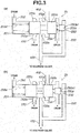
- FIGS. 3 are schematic views showing a structure of the pilot valve in the first embodiment.
- FIG. 3(a) shows an initial state before the generation of the hydraulic pressure.
- FIG. 3(b) shows a state when the pilot pressure is regulated. The components are illustrated by using the position relationship shown in FIG. 3(a) .
- the pilot valve 25 includes a valve receiving hole 251 formed within the control valve unit; a spool valve 250 received within the valve receiving hole 251; and a spring 250d arranged to urge the spool valve 250 in one direction.
- the spool valve 250 includes a first spool 250a including a feedback pressure land portion 250a1 arranged to receive the hydraulic pressure supplied from a pilot pressure feedback circuit 255; a second spool 250b arranged to regulate an opening degree of the line pressure port 402a; and a third spool 250c arranged to regulate connection states with the pilot pressure port 403a and the drain port 253a.
- the spring 250d is received between a bottom surface of the valve receiving hole 251 and the third spool 250c.
- the spring 250d urges on the pilot pressure feedback circuit 255's side.
- the spring 250d urges the spool valve 250 by the previously set predetermined spring set load.
- a drain circuit 252 is connected to the valve receiving hole 251 in which this spring 250d is received.
- a drain circuit 254 is connected to a portion between the first spool 250a and the second spool 250b. When the spool valve 250 is moved, the drain circuit 254 allows a volume variation of a space between the second spool 250b and the valve receiving hole 251. In this way, the drain circuits are connected to the both sides of the spool valve 250. With this, it is possible to ensure the smooth operation of the spool valve 250.
- the spool valve 250 When the line pressure is smaller than the first predetermined pressure which is the pilot pressure maximum value, it does not overcome the predetermined spring set load of the spring 250d, so that the spool valve 250 is not actuated. In this case, the hydraulic pressure is directly supplied from the line pressure port 402a to the pilot pressure port 403a. Consequently, the line pressure and the pilot pressure are the same.
- the spool valve 250 is started to be actuated as shown in FIG. 3(b) . That is, the force generated by acting the hydraulic pressure of the pilot pressure feedback circuit 255 to the feedback pressure land portion 250a1 becomes greater than the predetermined spring set load.
- the spool valve 250 is moved in the leftward direction of FIG. 3 (the spring 250d's side). With this, the opening of the line pressure port 402a becomes narrow by the second spool 250b. The line pressure is decreased by the orifice effect. The hydraulic pressure supplied to the pilot pressure feedback circuit 255 is also lowered. Moreover, when the line pressure is extremely high, the pilot pressure port 403a and the drain port 253a are connected by the movement of the third spool 250c. The line pressure supplied so that it becomes the pilot pressure is largely decreased from the drain circuit 253. In this way, the spool valve 250 is actuated by the pilot pressure supplied from the feedback circuit 255, so that the pilot pressure is regulated so as to have the first predetermined pressure which is the maximum value.
- FIG. 4 is a characteristic view showing a relationship among the line pressure, the pilot pressure, and the secondary pulley pressure in the continuously variable transmission according to the first embodiment.
- a lateral axis represents the line pressure.
- a longitudinal axis represents the hydraulic pressure.
- the line pressure becomes liner relationship.
- the pilot pressure is a hydraulic pressure regulated based on the line pressure.
- the secondary pulley pressure is a hydraulic pressure regulated based on the line pressure. In a region in which the line pressure is greater than the first predetermined pressure, the line pressure > the pilot pressure is satisfied. Even when the oil vibration is generated in the line pressure, the small influence is acted to the pilot pressure.
- the signal pressure outputted from the secondary solenoid valve 34 is difficult to receive the influence. Accordingly, there are few elements vibrated within the control valve. Consequently, the oil vibration is not increased due to the mutual interference within the control valve.
- the line pressure the pilot pressure
- the secondary solenoid valve 34 arranged to regulate the line pressure to the secondary pulley pressure receives the influence of the vibrated pilot pressure. Accordingly, the signal pressure discharged from the secondary regulator valve 27 is influenced by the vibration of the pilot pressure.
- the secondary pulley pressure is controlled, the influence of the oil vibration is received. In this way, when the oil vibration is generated in the region where the line pressure is equal to or smaller than the first predetermined pressure, the elements which are vibrated within the control valve are increased. Consequently, the oil vibration is increased by the mutual interference (interaction) within the control valve.
- FIG. 5 is a time chart when the oil vibration is generated when the vehicle travels in a state where the line pressure is smaller than the first predetermined pressure.
- a bold solid line is a tire rotation primary vibration frequency.
- a thin solid line is a natural frequency of the power train PT.
- a bold dotted line is an oil vibration frequency.
- One dot chain line is a natural frequency of the power train PT when the belt type continuously variable transmission CVT is the highest ratio.
- Two dot chain line is a natural frequency of the power train PT when the belt type continuously variable transmission CVT is the lowest ratio.
- the tire rotation primary frequency represents a primary frequency of the rotation vibration which is generated when the tires 8 are rotated, and which is easy to be felt by the occupant.
- the natural frequency of the power train PT represents an elastic torsion natural frequency which the power train PT transmits the power through a shaft and so on to the tires 8. Besides, this natural frequency is varied to the high frequency side when the belt type continuously variable transmission mechanism CVT is the High side, and varied to the low frequency side when the belt type continuously variable transmission mechanism CVT is the Low side.
- the vibration of the line pressure influences the pilot pressure.
- the oil vibration frequency for example, the line pressure frequency
- the tire rotation primary frequency and the natural frequency of the power train PT may be resonated.
- the forward/rearward acceleration vibration of the vehicle may be increased. Therefore, in this first embodiment, the line pressure is increased when the brake switch 17 is in the ON state, when the line pressure is equal to or smaller than the first predetermined pressure, and when the resonance of the various vibrations may be generated.
- a point of intersection of the oil vibration frequency of the line pressure (represented by the CVT oil vibration frequency in FIG. 5 ) and the natural frequency of the power train PT is represented by x1 (a second traveling state).
- a point of intersection of the oil vibration frequency and the tire rotation primary frequency is represented by x2 (a first traveling state).
- a point of intersection of the natural frequency of the power train PT and the tire rotation primary frequency is represented by x3 (a third traveling state).
- a point of intersection of the tire rotation primary frequency and the Lowest rate natural frequency is represented by x4.
- a point of intersection of the tire rotation primary frequency and the Highest rate natural frequency is x5.
- these frequencies are determined by their design specifications (design specification of the pressure regulator valve, the pump characteristics, design specification of the power train PT, tire diameter, and so on).
- the transmission gear ratio of the belt type continuously variable transmission mechanism CVT is upshifted from the Lowest side to the Highest side based on the vehicle speed VSP and the accelerator opening degree APO.
- the natural frequency of the power train PT is increased in accordance with this upshift.
- the tire rotation primary frequency is also increased in accordance with the increase of the vehicle speed VSP. Then, the forward/rearward acceleration G is vibrated by the influence of the oil vibration.
- the natural frequency of the power train PT and the oil vibration frequency are easy to be resonated near the intersection point x1.
- the forward/rearward accelerator vibration is easy to be generated.
- the tire rotation primary frequency and the oil vibration frequency are easy to be resonated near the intersection point t2. Furthermore, these are near the natural frequency of the power train PT. Accordingly, these and the natural frequency of the power train PT are easy to be resonated.
- the tire rotation frequency and the natural frequency of the power train PT are easy to be generated at the intersection point x3.
- the tire rotation primary frequency and the natural frequency of the power train PT may be resonated with the oil vibration frequency.
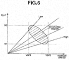
- FIG. 6 is a characteristic view showing a region in which the natural frequency of the power train PT and the tire rotation primary frequency are resonated when the oil vibration is generated in a state where the line pressure is smaller than the first predetermined pressure. It has been discovered that the resonance region near the intersection point x1 and the intersection point x2 exist in a region where the vehicle speed VSP is defined from VSP1 to VSP2, and in a region where the target primary rotation speed Npri* is defined from N1 to N2.
- this traveling state which has the intersection point x1, x2 and x3, and which induces the resonance is specified by the regions of the target primary rotation speed Npri* and the vehicle speed VSP.
- the line pressure is increased to the predetermined pressure greater than the first predetermined pressure, when the brake switch 17 is the ON state in the region of the above-described target primary rotation speed Npri* and the above-described vehicle speed VSP.
- the traveling state when the traveling state is determined based on the target primary rotation speed Npri* and the vehicle speed VSP, it may be determined, for example, by the traveling state including the intersection points x4 and x5.
- the intersection points x4 and x5 can be determined by the design specifications.
- the intersection points x4 and x5 can cover the entire region in which the natural frequency of the power train PT and the tire natural primary frequency may be resonated. This is because the region including these intersection points x4 and x5 causes the resonance due to the relationship between the oil vibration frequency, and the natural frequency of the power train PT and the tire rotation primary frequency.
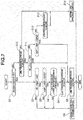
- FIG. 7 is a flowchart showing the line pressure increase control in the first embodiment.
- step S1 it is judged whether or not the brake switch 17 is in the ON state.
- the process proceeds to step S2. Otherwise, the process proceeds to step S10.
- step S2 it is judged whether or not the target primary rotation speed Npri* is within the predetermined rotation speed range (N1 ⁇ Npri* ⁇ N2).
- the process proceeds to step S3. Otherwise, the process proceeds to step S6.
- step S6 the brake correction torque control to increase the hydraulic pressure supplied to the secondary pulley 6 is performed.
- This predetermined rotation speed range is set based on the traveling state in which the above-described intersection points x1, x2, and x3 are included. Besides, by using the target primary rotation speed Npri*, it is possible to previously grasp the resonance range, and to attain the line pressure increase control with the higher response.
- step S3 it is judged whether or not the vehicle speed VSP is within the predetermined vehicle speed range (VSP1 ⁇ VSP ⁇ VSP2).
- the process proceeds to step S4. Otherwise, the process proceeds to step S6.
- step S6 the brake correction torque control to increase the hydraulic pressure supplied to the secondary pulley 6is performed.
- This predetermined vehicle speed range is set based on the traveling state in which the above-described intersection points x1, x2, and x3 are included.
- step S4 it is judged whether or not the line pressure is equal to or smaller than the first predetermined pressure.
- the process proceeds to step S5.
- step S5 the line pressure increase control is performed.
- step S6 the brake correction torque control to increase the hydraulic pressure supplied to the secondary pulley 6 is performed.
- a value obtained by subtracting a pressure obtained in consideration of safety factor from the first predetermined pressure may be used in place of the first predetermined pressure.
- the first predetermined pressure is not limited to these.
- the first predetermined pressure is previously determined by the design specifications of the pilot valve 25.
- the line pressure can be sensed from the command signal to the line pressure solenoid 30. Accordingly, it is judged whether or not the line pressure is equal to or smaller than the predetermined pressure, by comparing the current command signal to the line pressure solenoid 30, and the predetermined stored value corresponding to the first predetermined pressure. Besides, in a case where the line pressure sensor and so on which is arranged to sense the lie pressure, these can be compared by using the line pressure sensor signal.
- the line pressure increase flag is set to the ON state.
- the line pressure increase control is performed.
- the brake correction torque control to increase the secondary pulley pressure is performed. That is, the second predetermined pressure which is greater than the first predetermined pressure, and the target line pressure set by the brake correction torque control are compared.
- the line pressure is set to the hydraulic pressure of higher one of the above-comparison (select high).
- This second predetermined pressure is the value obtained by adding the third predetermined pressure obtained in consideration of the amplitude of the oil vibration which is previously obtained by the experiment and so on. With this, it is possible to further exclude the influence of the oil vibration to the pilot pressure, and to suppress the energy consumption without extremely increasing the line pressure.
- the second predetermined pressure may be the first predetermined pressure.
- the second predetermined pressure may be set in accordance with this amplitude of the line pressure. For example, a minimum value of oscillating (vibrating) line pressure is sensed. The second predetermined pressure is set so that this minimum value becomes smaller than the first predetermined pressure.
- step S10 it is judged whether or not the line pressure increase flag is in the ON state.
- the process proceeds to step 511.
- the line pressure increase flag is in the OFF state, the process proceeds to step S6.
- step S6 the brake correction torque control to increase the hydraulic pressure supplied to the secondary pulley 6 is performed.
- step S11 it is judged whether or not the target primary rotation speed Npri* is within the predetermined rotation speed range (N1 ⁇ Npri* ⁇ N2).
- the process proceeds to step S5 to continue the line pressure increase control. Otherwise, the process proceeds to step s12.
- step S12 it is judged whether or not the vehicle speed VSP is within the predetermined vehicle speed range (VSP1 ⁇ VSP ⁇ VSP2).
- the process proceeds to step S5 to continue the line pressure increase control. Otherwise, the process proceeds to step S13.
- step S13 the line pressure increase flag is set to the Off state.
- step S14 the normal line pressure control.
- the present invention has been illustrated based on the embodiment.
- the present invention includes the other structures.
- the regions of the target primary rotation speed Npri* and the vehicle speed VSP are the regions including the points of the intersections x1, x2, and x3.
- a region including at least x1 may be defined.
- a region including x1 and x2 may be defined.
- the line pressure increase control is performed when both of the condition of the target primary rotation speed Npri* and the condition of the vehicle speed VSP are satisfied.
- the line pressure increase control is performed when one of these conditions is satisfied.
- it is shifted from the line pressure increase control to the normal line pressure control, it is shifted to the normal line pressure control when the both of the condition of the target primary rotation speed Npri* and the condition of the vehicle speed VSP are not satisfied.
- one of these conditions is satisfied, it may be shifted to the normal lie pressure control.
- the resonance region when specified, it is judged by using the target primary rotation speed Npri*.
- the target primary rotation speed Npri* it is not limited to the target primary rotation speed Npri*. It is judged by using the actual primary rotation speed Npri.
- the line pressure and the first predetermined pressure are compared.
- the target line pressure when the brake correction torque control is performed and the first predetermined pressure may be compared. That is, in a case where the brake correction torque control to increase the secondary pulley pressure when the brake switch 17 is in the ON state, the line pressure increase may be performed when the line pressure increased by that brake correction torque control does not reach the first predetermined pressure. With this, it is possible to further exclude the influence of the oil vibration on the pilot pressure, and to improve the energy consumption without the excessive increase of the line pressure.
- the line pressure increase control is performed in the resonance region.
- the line pressure increase control may be performed simply based on the shift of the brake switch 17 to the ON state.
Landscapes
- Engineering & Computer Science (AREA)
- General Engineering & Computer Science (AREA)
- Mechanical Engineering (AREA)
- Control Of Transmission Device (AREA)
Abstract
Description
- This invention relates to a control device for a continuously variable transmission mounted on a vehicle.
- In a belt type continuously variable transmission, when a foot brake switch (hereinafter, referred to as a brake switch) is brought to an ON state by a depression of a brake pedal, a braking torque is transmitted from driving wheels to the continuously variable transmission, so that a belt slippage may be generated. A
patent document 1 discloses an art to prevent the belt slippage by increasing a belt clamping force of the continuously variable transmission when the brake switch is brought to the ON state. - In recent years, a hydraulic control of the transmission is often performed in a state where a line pressure is set to a low value, for improving fuel economy. In a case where the brake switch becomes the ON state when a vehicle travels in a state where the line pressure is lower than a pilot pressure that is a source pressure of a signal pressure for (of) various hydraulic actuators, an oil vibration may be generated due to the increase of the belt clamping force. That is, in a case where the belt clamping force is increased in a rage where the line pressure is lower than the pilot pressure, the vehicle behavior is varied due to the oil vibration even when the belt slippage.
- Patent Document 1: Japanese Patent Application Publication No.
2008-89146 - It is an object to provide a control device for a continuously variable transmission devised to solve the above-mentioned problems, and to suppress the variation of the vehicle behavior, and to suppress the unnatural feeling to the driver.
- For attaining the above-described objects, in this present invention, in a continuously variable transmission which includes a belt wound around a primary pulley and a secondary pulley, and which is shifted by controlling belt clamping forces of the primary pulley and the secondary pulley, there are provided a line pressure generating means configured to generate a line pressure; a pilot valve configured to supply a pilot pressure regulated so as not to exceed a first predetermined pressure when the line pressure exceeds the first predetermined pressure; a control means configured to generate the clamping forces by controlling the pilot pressure; and a line pressure increase means configured to increase the line pressure to be greater than the first predetermined pressure when the control to increase the line pressure is performed when the line pressure is lower than the first predetermined pressure.
- When the control to increase the hydraulic pressure is performed when the line pressure is lower than the first predetermined pressure which is the pilot pressure, the oil vibration may be generated due to the hydraulic pressure increase command. In this case, the line pressure is controlled to be greater than the first predetermined pressure. Accordingly, the pilot valve excludes the excessive hydraulic pressure of the varying line pressure.
It is possible to stably supply first predetermined pressure. Consequently, the clamping force is generated based on the stable pilot pressure. Therefore, it is possible to decrease the variation of the control hydraulic pressure according to the oil vibration. Accordingly, it is possible to prevent the mutual increase within the hydraulic circuit. -
-
FIG. 1 is a system diagram showing a control device of a continuously variable transmission according to a first embodiment. -
FIG. 2 is a hydraulic circuit diagram showing an outline (skeleton) within a control valve unit according to the first embodiment. -
FIGS. 3 are schematic views showing a construction of a pilot valve in the first embodiment. -
FIG. 4 is a characteristic view showing a relationship among a line pressure, a pilot pressure, and a secondary pulley pressure in the continuously variable transmission according to the first embodiment. -
FIG. 5 is a time chart in a case where an oil vibration is generated when a vehicle travels in a state where the line pressure is lower than a first predetermined pressure. -
FIG. 6 is a characteristic view showing a region in which a natural frequency of a power train PT and a tire rotation primary frequency are resonated when the oil vibration is generated in a state where the line pressure is lower than the first predetermined pressure. -
FIG. 7 is a flow chart showing a line pressure increase control in the first embodiment. -
FIG. 1 is a system diagram showing a control device of a continuously variable transmission according to a first embodiment. A vehicle according to the first embodiment includes anengine 1 which is an internal combustion engine, and the continuously variable transmission. A driving force is transmitted through a differential gear totires 8 which are driving wheels. A power transmitting path connected from a belt type continuously variable transmission mechanism CVT to thetires 8 is referred to as a power train PT. - The continuously variable transmission includes a
torque converter 2, anoil pump 3, and a forward/rearwardmovement switching mechanism 4, and the belt type continuously variable transmission mechanism CVT. Thetorque converter 2 includes apump impeller 2b connected to theengine 1, and arranged to rotate as a unit with a driving claw configured to drive theoil pump 3; aturbine runner 2c connected to an input side of the forward/rearward movement switching mechanism 4 (an input shaft of the belt type continuously variable transmission mechanism CVT); and a lock-up clutch 2a arranged to integrally connect thepump impeller 2b and theturbine runner 2c. The forward/rearwardmovement switching mechanism 4 includes a planetary gear mechanism, and a plurality ofclutches 4a. The forward/rearwardmovement switching mechanism 4 is arranged to switch the forward movement and the rearward movement in accordance with the engagement state of theclutch 4a. The belt type continuously variable transmission mechanism CVT includes aprimary pulley 5 connected to an output side of the forward/rearward movement switching mechanism 4 (an input shaft of the continuously variable transmission); asecondary pulley 6 arranged to rotate as a unit with driving wheels; a belt 7 wound around theprimary pulley 5 and thesecondary pulley 6 to transmit the power; and acontrol valve unit 20 arranged to supply control pressures to hydraulic actuators. - A
control unit 10 receives a range position signal (hereinafter, the range position signal is described as a P range, an R range, an N range, or a D range) from ashift lever 11 which is arranged to select a range position by an operation of a driver, an accelerator pedal opening degree signal (hereinafter, APO) from an accelerator pedalopening degree sensor 12, a brake pedal ON/OFF signal from abrake switch 17, a primary pulley pressure signal from a primarypulley pressure sensor 15 arranged to sense a hydraulic pressure of theprimary pulley 5, a secondary pulley pressure signal from a secondarypulley pressure sensor 16 arranged to sense a pressure of theprimary pulley 6, a primary pulley rotation speed signal Npri from a primary pulleyrotation speed sensor 13 arranged to sense a rotation speed of aprimary pulley 5, a secondary pulley rotation speed signal Nsec from a secondary pulleyrotation speed sensor 14 arranged to sense a rotation speed of thesecondary pulley 6, and an engine speed Ne from anengine speed sensor 15 arranged to sense an engine speed. Besides, the primary pulley rotation speed signal Npri is identical to the turbine rotation speed by the engagement of theclutch 4a in a case of the D range. Accordingly, hereinafter, the primary rotation speed signal Npri is also described as the turbine rotation speed Nt. - The
control unit 10 controls the engagement state of theclutch 4a in accordance with the range position signal. That is, thecontrol unit 10 is configured to control theclutch 4a to the disengagement state in case of the P range or the N range. Thecontrol unit 10 is configured to output a control signal to thecontrol valve unit 20 in case of the R range so that the forward/rearwardmovement switching mechanism 4 outputs the reverse rotation, and thereby to engage the rearward clutch (or the brake). Moreover, thecontrol unit 10 is arranged to output a control signal to thecontrol valve unit 20 in case of the D range so that the forward/reversemovement switching mechanism 4 rotates as a unit to output the positive rotation, and thereby to engage theforward clutch 4a. Furthermore, thecontrol unit 10 calculates a vehicle speed VSP based on the secondary rotation speed Nsec. - A shift map to attain an appropriate fuel economy state in accordance with a traveling state is set within the
control unit 10. A target transmission gear ratio (corresponding to a predetermined transmission gear ratio) is set based on the APO signal and the vehicle speed VSP based on this shift map. It is controlled by the feed forward control based on the target transmission gear ratio. The actual transmission gear ratio is sensed based on the primary pulley rotation speed signal Npri and the secondary pulley rotation speed signal Nsec. The feedback control is performed so that the set target transmission gear ratio and the actual transmission gear ratio become identical to (corresponds to) each other. That is, the target primary rotation speed Npri* is calculated from the current vehicle speed VSP and the target transmission gear ratio. The transmission gear ratio is controlled so that the turbine rotation speed Nt (the engine speed at the engagement of the lock-up clutch 2a) becomes the target primary rotation speed Npri*. Moreover, the hydraulic pressure commands of the pulleys and the engagement pressure command of the lock-up clutch 2a are outputted to thecontrol valve unit 20 by the feedback control, so that the hydraulic pressures of the pulleys and the lock-up pressure difference of the lock-upclutch 2a are controlled. Besides, in the first embodiment, a line pressure sensor is not provided within thecontrol valve unit 20. When the line pressure is sensed, the line pressure is sensed from the command signal to a line pressure solenoid valve 30 (described later). However, the line pressure sensor may be provided to sense the line pressure. - The
control unit 10 performs a brake correction torque control to increase the hydraulic pressure supplied to thesecondary pulley 6 when thebrake switch 17 is brought to the ON state. In the normal forward traveling state, the secondary pulley pressure which is a minimum clamping pressure for preventing the belt slippage is supplied for improving the fuel economy. In this case, when the braking torque is actuated to the driving wheels by the depression of the driver, the torque in a direction which is different from those of the driving wheels is inputted to thesecondary pulley 6. The belt slippage is easy to be generated. Accordingly, when thebrake switch 17 is brought to the ON state, the brake correction torque control to increase the secondary pulley pressure is performed. The brake correction torque control is a control to increase the clamping force by increasing the hydraulic pressure supplied to the secondary pulley 6 (the increase of the hydraulic pressure is largely increased as the previously set deceleration is larger) in accordance with the inertia torque calculated based on the transmission gear ratio when thebrake switch 17 is brought to the ON state, the previously set deceleration, and the engagement state of the lock-up clutch. The line pressure, and the hydraulic pressure supplied to theprimary pulley 5 is increased in accordance with this hydraulic pressure supplied to thesecondary pulley 6. When thebrake switch 17 is brought to the OFF state, the brake correction torque control is finished, so that the hydraulic pressure supplied to thesecondary pulley 6 is decreased and returned to the normal clamping pressure. -
FIG. 2 is a hydraulic circuit diagram showing an outline within the control valve unit in the first embodiment. The pump pressure discharged from theoil pump 3 driven by theengine 1 is discharged to thehydraulic passage 401, and regulated to the line pressure by thepressure regulator valve 21. Thehydraulic passage 401 is supplied, as the source pressures for the pulley hydraulic pressure, to the pulleys. Aprimary regulator valve 26 is connected to thehydraulic passage 401, and that pressure is regulated to the primary pulley pressure by theprimary regulator valve 26. Similarly, asecondary regulator valve 27 is connected to thehydraulic passage 401, and that pressure is regulated to the secondary pulley pressure by thesecondary regulator valve 27. Apilot valve 25 is provided in ahydraulic passage 402 bifurcated from thehydraulic passage 401. Thepilot valve 25 generates a previously set first predetermined pressure (corresponding to a predetermined pressure in claim 1) from the line pressure, and outputs the first predetermined pressure to the pilot pressurehydraulic passage 403. With this, the source pressure of the signal pressures outputted from the solenoid valves (described later) are generated. Besides, when the line pressure is equal to or smaller than the first predetermined pressure, the line pressure and the pilot pressure are outputted as the same pressure. - The
hydraulic passage 404 is connected to thepressure regulator valve 21, and that pressure is regulated to the engagement pressure of the clutch 4a by theclutch regulator valve 22. Thehydraulic passage 405 is connected to a torqueconverter regulator valve 23, and that pressure is regulated to the converter pressure of thetorque converter 2 by the torqueconverter regulator valve 23. Thehydraulic passage 406 bifurcated from thehydraulic passage 405 is connected to a lock-upvalve 24, and that pressure is regulated to the lock-up pressure of the lock-up clutch 2a by the lock-upvalve 24. In the lock-up clutch 2a, the lock-up control is performed by the lock-up pressure difference which is a pressure difference between the converter pressure and the lock-up pressure. In this way, theclutch regulator valve 22 is provided on the downstream side of thepressure regulator valve 21. The torqueconverter regulator valve 23 is provided on the more downstream side. With this, even when the excessively large torque is inputted from the engine, the belt slippage of the belt type continuously variable transmission CVT is prevented by the slippage of the lock-up clutch 2a and the slippage of the clutch 4a. - The pilot pressure
hydraulic passage 403 includes a linepressure solenoid valve 30 configured to control the line pressure; a clutchpressure solenoid valve 31 configured to control the clutch engagement pressure; a lock-upsolenoid valve 32 configured to control the lock-up pressure; aprimary solenoid valve 33 configured to control the primary pulley pressure; and asecondary solenoid valve 34 configured to control the secondary pulley pressure. The solenoid valves control the energization states of the solenoids based on the control signal outputted from thecontrol unit 10 to supply the signal pressure by using the pilot pressure as the source pressure to the valves, so as to control the pressure regulation states of the valves. - In this case, problems when the oil vibration is generated within the
control valve unit 20 are explained. As described above, various valves are provided within thecontrol valve unit 20. Thepressure regulator valve 21 is a valve arranged to regulate the highest hydraulic pressure discharged from theoil pump 3. Accordingly, thepressure regulator valve 21 is easy to receive the influence of the pump pulsation. A spool and so on constituting thepressure regulator valve 21 is vibrated in accordance with design specifications of valve diameter, an inertia, and so on, so that the line pressure may be vibrated (hereinafter, described as oil vibration). The line pressure may be (is often) varied in a stepped manner from the low line pressure, for increasing the secondary pulley pressure in accordance with the brake correction torque control. In this case, the oil vibration may be (is often) generated due to the sudden variation of this line pressure. Moreover, the line pressure is set in accordance with the accelerator pedal opening degree APO. Accordingly, the line pressure is set to the low value when the accelerator pedal opening degree APO is small. The line pressure is set to the large value when the accelerator pedal opening degree APO is large. -
FIGS. 3 are schematic views showing a structure of the pilot valve in the first embodiment.FIG. 3(a) shows an initial state before the generation of the hydraulic pressure.FIG. 3(b) shows a state when the pilot pressure is regulated. The components are illustrated by using the position relationship shown inFIG. 3(a) . Thepilot valve 25 includes avalve receiving hole 251 formed within the control valve unit; aspool valve 250 received within thevalve receiving hole 251; and aspring 250d arranged to urge thespool valve 250 in one direction. Thespool valve 250 includes afirst spool 250a including a feedback pressure land portion 250a1 arranged to receive the hydraulic pressure supplied from a pilotpressure feedback circuit 255; asecond spool 250b arranged to regulate an opening degree of theline pressure port 402a; and athird spool 250c arranged to regulate connection states with thepilot pressure port 403a and thedrain port 253a. - The
spring 250d is received between a bottom surface of thevalve receiving hole 251 and thethird spool 250c. Thespring 250d urges on the pilotpressure feedback circuit 255's side. Thespring 250d urges thespool valve 250 by the previously set predetermined spring set load. Adrain circuit 252 is connected to thevalve receiving hole 251 in which thisspring 250d is received. Moreover, adrain circuit 254 is connected to a portion between thefirst spool 250a and thesecond spool 250b. When thespool valve 250 is moved, thedrain circuit 254 allows a volume variation of a space between thesecond spool 250b and thevalve receiving hole 251. In this way, the drain circuits are connected to the both sides of thespool valve 250. With this, it is possible to ensure the smooth operation of thespool valve 250. - When the line pressure is smaller than the first predetermined pressure which is the pilot pressure maximum value, it does not overcome the predetermined spring set load of the
spring 250d, so that thespool valve 250 is not actuated. In this case, the hydraulic pressure is directly supplied from theline pressure port 402a to thepilot pressure port 403a. Consequently, the line pressure and the pilot pressure are the same. Next, when the line pressure is equal to or greater than the first predetermined pressure which is the pilot pressure maximum value, thespool valve 250 is started to be actuated as shown inFIG. 3(b) . That is, the force generated by acting the hydraulic pressure of the pilotpressure feedback circuit 255 to the feedback pressure land portion 250a1 becomes greater than the predetermined spring set load. With this, thespool valve 250 is moved in the leftward direction ofFIG. 3 (thespring 250d's side). With this, the opening of theline pressure port 402a becomes narrow by thesecond spool 250b. The line pressure is decreased by the orifice effect. The hydraulic pressure supplied to the pilotpressure feedback circuit 255 is also lowered. Moreover, when the line pressure is extremely high, thepilot pressure port 403a and thedrain port 253a are connected by the movement of thethird spool 250c. The line pressure supplied so that it becomes the pilot pressure is largely decreased from thedrain circuit 253. In this way, thespool valve 250 is actuated by the pilot pressure supplied from thefeedback circuit 255, so that the pilot pressure is regulated so as to have the first predetermined pressure which is the maximum value. -
FIG. 4 is a characteristic view showing a relationship among the line pressure, the pilot pressure, and the secondary pulley pressure in the continuously variable transmission according to the first embodiment. A lateral axis represents the line pressure. A longitudinal axis represents the hydraulic pressure. The line pressure becomes liner relationship. As illustrated in the hydraulic circuit structure ofFIG. 3 , the pilot pressure is a hydraulic pressure regulated based on the line pressure. The secondary pulley pressure is a hydraulic pressure regulated based on the line pressure. In a region in which the line pressure is greater than the first predetermined pressure, the line pressure > the pilot pressure is satisfied. Even when the oil vibration is generated in the line pressure, the small influence is acted to the pilot pressure. The signal pressure outputted from thesecondary solenoid valve 34 is difficult to receive the influence. Accordingly, there are few elements vibrated within the control valve. Consequently, the oil vibration is not increased due to the mutual interference within the control valve. - On the other hand, in a region where the line pressure is equal to or smaller than the first predetermined pressure, the line pressure = the pilot pressure is satisfied. At this time, when the oil vibration is generated in the line pressure, the pilot pressure is also vibrated. Moreover, the
secondary solenoid valve 34 arranged to regulate the line pressure to the secondary pulley pressure receives the influence of the vibrated pilot pressure. Accordingly, the signal pressure discharged from thesecondary regulator valve 27 is influenced by the vibration of the pilot pressure. When the secondary pulley pressure is controlled, the influence of the oil vibration is received. In this way, when the oil vibration is generated in the region where the line pressure is equal to or smaller than the first predetermined pressure, the elements which are vibrated within the control valve are increased. Consequently, the oil vibration is increased by the mutual interference (interaction) within the control valve. -
FIG. 5 is a time chart when the oil vibration is generated when the vehicle travels in a state where the line pressure is smaller than the first predetermined pressure. InFIG. 5 , a bold solid line is a tire rotation primary vibration frequency. A thin solid line is a natural frequency of the power train PT. A bold dotted line is an oil vibration frequency. One dot chain line is a natural frequency of the power train PT when the belt type continuously variable transmission CVT is the highest ratio. Two dot chain line is a natural frequency of the power train PT when the belt type continuously variable transmission CVT is the lowest ratio. In this case, the tire rotation primary frequency represents a primary frequency of the rotation vibration which is generated when thetires 8 are rotated, and which is easy to be felt by the occupant. Moreover, the natural frequency of the power train PT represents an elastic torsion natural frequency which the power train PT transmits the power through a shaft and so on to thetires 8. Besides, this natural frequency is varied to the high frequency side when the belt type continuously variable transmission mechanism CVT is the High side, and varied to the low frequency side when the belt type continuously variable transmission mechanism CVT is the Low side. - As shown in
FIG. 5 , the vibration of the line pressure influences the pilot pressure. The oil vibration frequency (for example, the line pressure frequency) within the control valve, and the tire rotation primary frequency and the natural frequency of the power train PT may be resonated. With this, the forward/rearward acceleration vibration of the vehicle may be increased. Therefore, in this first embodiment, the line pressure is increased when thebrake switch 17 is in the ON state, when the line pressure is equal to or smaller than the first predetermined pressure, and when the resonance of the various vibrations may be generated. - As shown in
FIG.5 , a point of intersection of the oil vibration frequency of the line pressure (represented by the CVT oil vibration frequency inFIG. 5 ) and the natural frequency of the power train PT is represented by x1 (a second traveling state). A point of intersection of the oil vibration frequency and the tire rotation primary frequency is represented by x2 (a first traveling state). A point of intersection of the natural frequency of the power train PT and the tire rotation primary frequency is represented by x3 (a third traveling state). A point of intersection of the tire rotation primary frequency and the Lowest rate natural frequency is represented by x4. A point of intersection of the tire rotation primary frequency and the Highest rate natural frequency is x5. Besides, these frequencies are determined by their design specifications (design specification of the pressure regulator valve, the pump characteristics, design specification of the power train PT, tire diameter, and so on). - As shown in the vibration state of the forward/rearward acceleration G of
FIG. 5 , when the vehicle is started and gradually accelerated, the transmission gear ratio of the belt type continuously variable transmission mechanism CVT is upshifted from the Lowest side to the Highest side based on the vehicle speed VSP and the accelerator opening degree APO. The natural frequency of the power train PT is increased in accordance with this upshift. The tire rotation primary frequency is also increased in accordance with the increase of the vehicle speed VSP. Then, the forward/rearward acceleration G is vibrated by the influence of the oil vibration. - At time t1, the natural frequency of the power train PT and the oil vibration frequency are easy to be resonated near the intersection point x1. The forward/rearward accelerator vibration is easy to be generated.
- Moreover, at time t2, the tire rotation primary frequency and the oil vibration frequency are easy to be resonated near the intersection point t2. Furthermore, these are near the natural frequency of the power train PT. Accordingly, these and the natural frequency of the power train PT are easy to be resonated.
- Moreover, at time t3, the tire rotation frequency and the natural frequency of the power train PT are easy to be generated at the intersection point x3. By this influence, the tire rotation primary frequency and the natural frequency of the power train PT may be resonated with the oil vibration frequency.
-
FIG. 6 is a characteristic view showing a region in which the natural frequency of the power train PT and the tire rotation primary frequency are resonated when the oil vibration is generated in a state where the line pressure is smaller than the first predetermined pressure. It has been discovered that the resonance region near the intersection point x1 and the intersection point x2 exist in a region where the vehicle speed VSP is defined from VSP1 to VSP2, and in a region where the target primary rotation speed Npri* is defined from N1 to N2. - Accordingly, this traveling state which has the intersection point x1, x2 and x3, and which induces the resonance is specified by the regions of the target primary rotation speed Npri* and the vehicle speed VSP. The line pressure is increased to the predetermined pressure greater than the first predetermined pressure, when the
brake switch 17 is the ON state in the region of the above-described target primary rotation speed Npri* and the above-described vehicle speed VSP. With this, even when the oil vibration is generated in the line pressure due to the brake correction torque control in a case where the secondary pulley pressure is increased by the brake correction torque control, the line pressure becomes higher than the first predetermined pressure. Accordingly, it is possible to exclude the increase of the oil vibration due to the mutual interference within the control valve, and to suppress the resonance with the other vibration components. Besides, when the traveling state is determined based on the target primary rotation speed Npri* and the vehicle speed VSP, it may be determined, for example, by the traveling state including the intersection points x4 and x5. The intersection points x4 and x5 can be determined by the design specifications. The intersection points x4 and x5 can cover the entire region in which the natural frequency of the power train PT and the tire natural primary frequency may be resonated. This is because the region including these intersection points x4 and x5 causes the resonance due to the relationship between the oil vibration frequency, and the natural frequency of the power train PT and the tire rotation primary frequency. -
FIG. 7 is a flowchart showing the line pressure increase control in the first embodiment. - At step S1, it is judged whether or not the
brake switch 17 is in the ON state. When the ON state is judged, the process proceeds to step S2. Otherwise, the process proceeds to step S10. - At step S2, it is judged whether or not the target primary rotation speed Npri* is within the predetermined rotation speed range (N1≤Npri*≤N2). When the target primary rotation speed Npri* is within the predetermined rotation speed, the process proceeds to step S3. Otherwise, the process proceeds to step S6. At step S6, the brake correction torque control to increase the hydraulic pressure supplied to the
secondary pulley 6 is performed. This predetermined rotation speed range is set based on the traveling state in which the above-described intersection points x1, x2, and x3 are included. Besides, by using the target primary rotation speed Npri*, it is possible to previously grasp the resonance range, and to attain the line pressure increase control with the higher response. - At step S3, it is judged whether or not the vehicle speed VSP is within the predetermined vehicle speed range (VSP1≤VSP≤VSP2). When the vehicle speed VSP is within the predetermined vehicle speed range, the process proceeds to step S4. Otherwise, the process proceeds to step S6. At step S6, the brake correction torque control to increase the hydraulic pressure supplied to the secondary pulley 6is performed. This predetermined vehicle speed range is set based on the traveling state in which the above-described intersection points x1, x2, and x3 are included.
- At step S4, it is judged whether or not the line pressure is equal to or smaller than the first predetermined pressure. When the line pressure is equal to or smaller than the first predetermined pressure, the process proceeds to step S5. At step S5, the line pressure increase control is performed. When the line pressure is greater than the first predetermined pressure, the process proceeds to step S6. At step S6, the brake correction torque control to increase the hydraulic pressure supplied to the
secondary pulley 6 is performed. Besides, a value obtained by subtracting a pressure obtained in consideration of safety factor from the first predetermined pressure may be used in place of the first predetermined pressure. The first predetermined pressure is not limited to these. Besides, the first predetermined pressure is previously determined by the design specifications of thepilot valve 25. The line pressure can be sensed from the command signal to theline pressure solenoid 30. Accordingly, it is judged whether or not the line pressure is equal to or smaller than the predetermined pressure, by comparing the current command signal to theline pressure solenoid 30, and the predetermined stored value corresponding to the first predetermined pressure. Besides, in a case where the line pressure sensor and so on which is arranged to sense the lie pressure, these can be compared by using the line pressure sensor signal. - At step S41, the line pressure increase flag is set to the ON state.
- At step S5, the line pressure increase control is performed. At this time, the brake correction torque control to increase the secondary pulley pressure is performed. That is, the second predetermined pressure which is greater than the first predetermined pressure, and the target line pressure set by the brake correction torque control are compared. Then, the line pressure is set to the hydraulic pressure of higher one of the above-comparison (select high). This second predetermined pressure is the value obtained by adding the third predetermined pressure obtained in consideration of the amplitude of the oil vibration which is previously obtained by the experiment and so on. With this, it is possible to further exclude the influence of the oil vibration to the pilot pressure, and to suppress the energy consumption without extremely increasing the line pressure. Moreover, the second predetermined pressure may be the first predetermined pressure. Furthermore, the amplitude of the line pressure is sensed. The second predetermined pressure may be set in accordance with this amplitude of the line pressure. For example, a minimum value of oscillating (vibrating) line pressure is sensed. The second predetermined pressure is set so that this minimum value becomes smaller than the first predetermined pressure. When the secondary pulley pressure is increased in this state, it is possible to increase the clamping force of the
secondary pulley 6 in a state where the influence of the oil vibration is excluded, and to stably ensure the vehicle behavior and so on. - At step S10, it is judged whether or not the line pressure increase flag is in the ON state. When the line pressure increase flag is in the ON state, the process proceeds to step 511. When the line pressure increase flag is in the OFF state, the process proceeds to step S6. At step S6, the brake correction torque control to increase the hydraulic pressure supplied to the
secondary pulley 6 is performed. - At step S11, it is judged whether or not the target primary rotation speed Npri* is within the predetermined rotation speed range (N1≤Npri*≤N2). When the target primary rotation speed Npri* is within the predetermined rotation speed range, the process proceeds to step S5 to continue the line pressure increase control. Otherwise, the process proceeds to step s12.
- At step S12, it is judged whether or not the vehicle speed VSP is within the predetermined vehicle speed range (VSP1≤VSP≤VSP2). When the vehicle speed VSP is within the predetermined opening degree range, the process proceeds to step S5 to continue the line pressure increase control. Otherwise, the process proceeds to step S13.
- At step S13, the line pressure increase flag is set to the Off state. The process proceeds to step S14 to perform the normal line pressure control.
- In this way, it is possible to exclude the influence of the oil vibration by increasing the line pressure in the traveling state in which it is conceivable to include the intersection points x1, x2, and x3, when the
brake switch 17 is in the ON state, and when the line pressure is smaller than the predetermined pilot pressure. With this, it is possible to suppress the resonance with the tire rotation primary frequency and the natural frequency of the power train PT, and to maintain the stable engagement state. - Moreover, it proceeds to the normal line pressure control to allow the decrease of the line pressure when it is confirmed that it proceeds to the region other than the resonance region, when the
brake switch 17 is brought to the OFF state while the line pressure increase control is performed in the ON state of the line pressure increase flag. In this way, even when thebrake switch 17 is brought to the OFF state, the oil vibration may be generated again in the resonance region due to the decrease of the line pressure and so on. Accordingly, the line pressure increase control is continued. On the other hand, in a case where it is departed from the resonance region, the resonance is not generated. Accordingly, in this case, it is rapidly returned to the normal line pressure control. With this, it is possible to improve the fuel economy. - As described above, it is possible to attain following operations and effects in this embodiment.
- (1) In the belt type continuously variable transmission mechanism CVT which includes a belt 7 wound around the
primary pulley 5 and thesecondary pulley 6, and which is shifted by controlling the pulley hydraulic pressures (the belt clamping forces) of theprimary pulley 5 and thesecondary pulley 6, there are provided:- the
oil pump 3 and the pressure regulator valve 21 (line pressure generating means) arranged to generate the line pressure; - the
pilot valve 25 arranged to supply the pilot pressure regulated so as not to exceed the first predetermined pressure when the line pressure exceeds the first predetermined pressure; - the control unit 10 (the control means) configured to generate the pulley hydraulic pressure by controlling the solenoid valve by the pilot pressure; and
- the step S4 and the step S5 (the line pressure increasing means) configured to increase the line pressure to be greater than the first predetermined pressure when the control to increase the line pressure is performed when the line pressure is lower than the first predetermined pressure.
In a case where the command to increase the hydraulic pressure is outputted when the line pressure is lower than the pilot pressure, the oil vibration may be generated in the line pressure due to the variation of the hydraulic pressure. In this case, in the first embodiment, the line pressure is controlled to be greater than the first predetermined pressure. Accordingly, even when the oil vibration is generated in the line pressure, thepilot valve 25 excludes the excessive hydraulic pressure varied based on the relationship between the feedback hydraulic pressure and thespring 250d. Consequently, it is possible to stably supply the first predetermined pressure. Therefore, it is possible to decrease the variations of the other hydraulic actuators according to the oil vibration since the other solenoid valves are controlled based on the stable pilot pressure. Accordingly, it is possible to prevent the mutual increase of the oil vibrations within the hydraulic circuit, and to suppress the unnatural feeling to the driver. - the
- (2) There is provided the brake switch 17 (the brake operation sensing means) arranged to sense the depression of the brake pedal. The
control unit 10 is configured to increase the line pressure to be greater than the first predetermined pressure when thebrake switch 17 is brought to the ON state when the line pressure is lower than the first predetermined pressure.
Accordingly, it is possible to exclude the influence by the vibration of the line pressure, and to prevent the belt slippage. - (3) The
control unit 10 is configured to perform the brake correction torque control to increase the clamping force of the pulley by increasing the line pressure in accordance with the deceleration of the vehicle when the depression of the brake pedal is sensed, and to increase the line pressure to be greater than the first predetermined pressure when the line pressure which is increased by the brake correction torque control is lower than the first predetermined pressure.
When the brake correction torque control is performed, the clamping forces are increased by increasing the line pressure in accordance with the deceleration of the vehicle, for preventing the belt slippage. In this case, in a case where the clamping forces are increased in the range lower than the first predetermined pressure, the pilot pressure is vibrated when the oil vibration is generated. With this, the oil vibration is influenced on the clamping forces to provide the unnatural feeling to the driver. On the other hand, in the first embodiment, the line pressure is increased to be greater than the first predetermined pressure, irrespective of the increase of the line pressure by the brake correction torque control. Accordingly, when the oil vibration is generated in the line pressure, it is possible to ensure the stable pilot pressure. Consequently, it is possible to prevent the mutual increase of the oil vibration within the hydraulic circuit, and to suppress the unnatural feeling to the driver. - (4) The
control unit 10 is configured to increase the line pressure to be greater than the first predetermined pressure when the line pressure set in accordance with the traveling state is equal to or smaller than the first predetermined pressure when thebrake switch 17 is the ON state at the point x2 of intersection (the first traveling state) at which the tire rotation primary frequency and the oil vibration frequency corresponds to each other.
Accordingly, in the brake correction torque control, the line pressure becomes greater than the first predetermined pressure in the first traveling state in which the tire rotation primary frequency and the oil vibration frequency corresponds to each other even when the line pressure is lower than the first predetermined pressure, and the pilot pressure is identical to the line pressure. Consequently, it is possible to increase the line pressure to be greater than the pilot pressure. Therefore, even when the oil vibration is generated in the line pressure, it is possible to decrease the influence on the pilot pressure, to decrease the elements vibrated within the control valve, and to suppress the increase of the oil vibration due the mutual interference. With this, even when the rotation primary frequency of the tire and the oil vibration frequency of the control valve correspond to each other, it is possible to suppress the resonance between the oil vibration frequency and the tire primary frequency. Accordingly, it is possible to stably perform the brake correction torque control, and to suppress the unnatural feeling according to the behavior variation of the vehicle to the driver. - (5) The
control unit 10 is configured to increase the line pressure to be greater than the first predetermined pressure when the line pressure is equal to or smaller than the first predetermined pressure when thebrake switch 17 is in the ON state at the point x1 of intersection (the second traveling state) at which the oil vibration frequency of the line pressure and the natural frequency of the power train PT (the torsion natural frequency between the continuously variable transmission and the tires.
Accordingly, even when the oil vibration is generated in the line pressure due to the increase of the line pressure according to the brake correction torque control, it is possible to stably supply the first predetermined pressure without the influence on the pilot pressure. Consequently, it is possible to suppress the resonance with the natural frequency of the power train PT. Therefore, it is possible to stably perform the brake correction torque control, and to suppress the unnatural feeling according to the variation and so on of the forward/rearward acceleration to the driver. - (6) The
control unit 10 is configured to increase the line pressure to be greater than the predetermined pressure when the line pressure is equal to or greater than the first predetermined pressure when the brake switch is in the ON state at the point x3 of the intersection (the third traveling state) at which the rotation primary frequency of the tire and the natural frequency of the power train PT corresponds to each other.
Accordingly, even when oil vibration is generated in the line pressure by the increase of the line pressure according to the brake correction control, it is possible to stably maintain the engagement state of the lock-up clutch 2a without the influence on the pilot pressure. Consequently, even when the resonance of the primary rotation frequency of the tire and the natural frequency of the power train PT are generated, it is possible to suppress the resonance of that resonance and the oil vibration frequency. Therefore, it is possible to stably perform the brake correction torque control, and to suppress the unnatural feeling according to the variation and so on of the forward/rearward acceleration to the driver. - (7) The
control unit 10 is configured to increase the line pressure to be greater than the first predetermined pressure when the line pressure is smaller than the first predetermined pressure when thebrake switch 17 is the ON state, and when the target primary rotation speed Npri* is within the predetermined rotation speed range including the point x2 of the intersection.
Accordingly, it is possible to specify the traveling state by the simple structure. Besides, it is optional to specify the traveling state by the points of the intersections x1 and x3, and also the points of the intersection x4 and x5, in addition to the point of the intersection x2. - (8) The
control unit 10 is configured to increase the line pressure to be greater than the first predetermined pressure when the line pressure is equal to or smaller than the first predetermined pressure when the brake switch is in the ON state, and when the vehicle speed VSP is within the predetermined vehicle speed range including the point x2 of the intersection.
Accordingly, it is possible to specify the traveling state by the simple structure. Besides, it is optional to specify the traveling state by the points of the intersections x1 and x3, and also the points of the intersection x4 and x5, in addition to the point of the intersection x2. - (9) The
control unit 10 is configured to finish the line pressure increase control when the line pressure is increased, when thebrake switch 17 is in the OFF state, and when the target primary rotation speed Npri* is out of the range defined by N1 and N2 (out of the predetermined rotation speed range).
Even when thebrake switch 17 is in the OFF state, and when the brake correction torque control is finished, the oil vibration may be caused in the resonance region in accordance with the decrease of the line pressure. Accordingly, the line pressure increase control is continued in the resonance region. With this, it is possible to suppress the unnatural feeling to the driver. Moreover, when it is out of the resonance region, it is possible to decrease the line pressure while avoiding the generation of the resonance. Consequently, it is possible to improve the fuel consumption without providing the unnatural feeling to the driver. - (10) The control unit is configured to finish the line pressure increase control when the line pressure is increased, when the
brake switch 17 is in the OFF state, and when the vehicle speed VSP is out of the range defined by VSP1 and VSP2 (out of the predetermined vehicle speed range). - Even when the
brake switch 17 is in the OFF state, and when the brake correction torque control is finished, the oil vibration may be caused in the resonance region in accordance with the decrease of the line pressure. Accordingly, the line pressure increase control is continued in the resonance region. With this, it is possible to suppress the unnatural feeling to the driver. Moreover, when it is out of the resonance region, it is possible to decrease the line pressure while avoiding the generation of the resonance, by the end of the line pressure increase control. Consequently, it is possible to improve the fuel consumption without providing the unnatural feeling to the driver. - Hereinbefore, the present invention has been illustrated based on the embodiment. The present invention includes the other structures. For example, in the first embodiment, the regions of the target primary rotation speed Npri* and the vehicle speed VSP are the regions including the points of the intersections x1, x2, and x3. However, a region including at least x1 may be defined. A region including x1 and x2 may be defined.
- Moreover, in the first embodiment, when the resonance region is specified, the line pressure increase control is performed when both of the condition of the target primary rotation speed Npri* and the condition of the vehicle speed VSP are satisfied. However, the line pressure increase control is performed when one of these conditions is satisfied. Furthermore, when it is shifted from the line pressure increase control to the normal line pressure control, it is shifted to the normal line pressure control when the both of the condition of the target primary rotation speed Npri* and the condition of the vehicle speed VSP are not satisfied. However, when one of these conditions is satisfied, it may be shifted to the normal lie pressure control.
- Moreover, in the first embodiment, when the resonance region is specified, it is judged by using the target primary rotation speed Npri*. However, it is not limited to the target primary rotation speed Npri*. It is judged by using the actual primary rotation speed Npri.
- Furthermore, at step S4 in the first embodiment, the line pressure and the first predetermined pressure are compared. However, the target line pressure when the brake correction torque control is performed and the first predetermined pressure may be compared. That is, in a case where the brake correction torque control to increase the secondary pulley pressure when the
brake switch 17 is in the ON state, the line pressure increase may be performed when the line pressure increased by that brake correction torque control does not reach the first predetermined pressure. With this, it is possible to further exclude the influence of the oil vibration on the pilot pressure, and to improve the energy consumption without the excessive increase of the line pressure. - Furthermore, in the first embodiment, the line pressure increase control is performed in the resonance region. However, the line pressure increase control may be performed simply based on the shift of the
brake switch 17 to the ON state.
Claims (10)
- A control device for a continuously variable transmission which includes a belt wound around a primary pulley and a secondary pulley, and which is shifted by controlling belt clamping forces of the primary pulley and the secondary pulley, the control device comprising:a line pressure generating means configured to generate a line pressure;a pilot valve configured to supply a pilot pressure regulated so as not to exceed a first predetermined pressure when the line pressure exceeds the first predetermined pressure;a control means configured to generate the clamping forces by controlling the pilot pressure; anda line pressure increase means configured to increase the line pressure to be greater than the first predetermined pressure when the control to increase the line pressure is performed when the line pressure is lower than the first predetermined pressure.
- The control device for the continuously variable transmission as claimed in claim 1, wherein the control device further comprises a brake operation sensing means arranged to sense a depression of a brake pedal; the line pressure increasing means is configured to increase the line pressure to be greater than the first predetermined pressure to increase the clamping force of the pulley when the depression of the brake pedal is sensed when the line pressure is lower than the first predetermined pressure.
- The control device for the continuously variable transmission as claimed in claim 1, wherein the line pressure increasing means is configured to perform the brake correction torque control to increase the clamping force of the pulley by increasing the line pressure in accordance with the deceleration of the vehicle when the depression of the brake pedal is sensed, and to increase the line pressure to be greater than the first predetermined pressure when the line pressure increased by the brake correction torque control is lower than the first predetermined pressure.
- The control device for the continuously variable transmission as claimed in claim 2 or 3, wherein the line pressure increasing means is configured to increase the line pressure to be greater than the first predetermined pressure when the line pressure set according to the traveling state is equal to or smaller than the first predetermined pressure when the brake pedal is depressed in a first traveling state where the tire rotation primary frequency and the oil vibration frequency correspond to each other.
- The control device for the continuously variable transmission as claimed in one of claims 2 to 4, wherein the line pressure increase means is configured to increase the line pressure to be greater than the first predetermined pressure when the line pressure is smaller than the first predetermined pressure when the brake pedal is depressed in a state where a second traveling state where torsion natural frequencies between the continuously variable transmission and the tire correspond to each other.
- The control device for the continuously variable transmission as claimed in one of claims 2 to 5, wherein the line pressure increase means is configured to increase the line pressure to be greater than the first predetermined pressure when the line pressure is equal to or smaller than the first predetermined pressure when the brake pedal is depressed in a third traveling state where the torsion natural frequencies between the continuously variable transmission and the tire correspond to each other.
- The control device for the continuously variable transmission as claimed in one of claims 3 to 6, wherein the line pressure increase means is configured to increase the line pressure to be greater than the first predetermined pressure when the line pressure is equal to or smaller than the first predetermined pressure when the brake pedal is depressed, and when the primary rotation speed is within a predetermined rotation speed range including the first traveling state.
- The control device for the continuously variable transmission as claimed in one of claims 3 to 7, wherein the line pressure increase means is configured to increase the line pressure to be greater than the first predetermined pressure when the line pressure is equal to or smaller than the first predetermined pressure when the brake pedal is depressed, and when the vehicle speed is within a predetermined vehicle speed range including the first traveling state.
- The control device for the continuously variable transmission as claimed in claim 8, wherein the line pressure increasing means is configured to return the line pressure to the hydraulic pressure set in accordance with the traveling state when the brake pedal is not depressed and when the primary rotation speed is not within the predetermined rotation speed range when the line pressure is increased.
- The control device for the continuously variable transmission as claimed in claim 8, wherein the line pressure increasing means is configured to return the line pressure to the hydraulic pressure set in accordance with the traveling state when the brake pedal is not depressed and when the vehicle speed is not within the predetermined vehicle speed range when the line pressure is increased.
Applications Claiming Priority (2)
| Application Number | Priority Date | Filing Date | Title |
|---|---|---|---|
| JP2014141741 | 2014-07-09 | ||
| PCT/JP2015/065330 WO2016006356A1 (en) | 2014-07-09 | 2015-05-28 | Control device for continuously variable transmission |
Publications (2)
| Publication Number | Publication Date |
|---|---|
| EP3168502A1 true EP3168502A1 (en) | 2017-05-17 |
| EP3168502A4 EP3168502A4 (en) | 2017-08-09 |
Family
ID=55063998
Family Applications (1)
| Application Number | Title | Priority Date | Filing Date |
|---|---|---|---|
| EP15819707.9A Withdrawn EP3168502A4 (en) | 2014-07-09 | 2015-05-28 | Control device for continuously variable transmission |
Country Status (6)
| Country | Link |
|---|---|
| US (1) | US10364888B2 (en) |
| EP (1) | EP3168502A4 (en) |
| JP (1) | JP6326494B2 (en) |
| KR (1) | KR101914354B1 (en) |
| CN (1) | CN106662241B (en) |
| WO (1) | WO2016006356A1 (en) |
Families Citing this family (7)
| Publication number | Priority date | Publication date | Assignee | Title |
|---|---|---|---|---|
| CN107406067B (en) * | 2015-03-05 | 2020-09-01 | 加特可株式会社 | Control device for hybrid vehicle |
| US10161517B1 (en) * | 2017-06-07 | 2018-12-25 | GM Global Technology Operations LLC | Method and apparatus to control a continuously variable transmission |
| JP6874656B2 (en) * | 2017-11-27 | 2021-05-19 | 日産自動車株式会社 | Control method and control device for automatic transmission |
| JP7155725B2 (en) * | 2018-08-06 | 2022-10-19 | トヨタ自動車株式会社 | Control device for vehicle drive system |
| US11242927B2 (en) * | 2019-05-23 | 2022-02-08 | GM Global Technology Operations LLC | Robust hydraulic system disturbance detection and mitigation |
| JPWO2022091637A1 (en) | 2020-11-02 | 2022-05-05 | ||
| CN115917187B (en) | 2020-11-02 | 2025-05-02 | 加特可株式会社 | Damping pressure supply circuit with pulley pressure control valve |
Family Cites Families (28)
| Publication number | Priority date | Publication date | Assignee | Title |
|---|---|---|---|---|
| JPS62292958A (en) * | 1986-06-11 | 1987-12-19 | Shimadzu Corp | hydraulic system |
| US4964317A (en) | 1987-08-10 | 1990-10-23 | Suzuki Jidosha Kogyo Kabushiki Kaisha | Hydraulic control method for continuously variable speed change gear mechanism for a vehicle and a drive control method for a pressure valve thereof |
| JP2757304B2 (en) * | 1988-08-25 | 1998-05-25 | マツダ株式会社 | Transmission hydraulic control device |
| US5031481A (en) * | 1989-12-08 | 1991-07-16 | Borg-Warner Automotive, Inc. | Electro-hydraulic control system for a dual-pass continuously variable transmission |
| EP0440422B1 (en) * | 1990-02-01 | 1995-04-12 | Toyota Jidosha Kabushiki Kaisha | Hydraulic control apparatus for belt-and-pulley type continuously variable transmission, incorporating means for optimizing belt tensioning pressure |
| JPH05106714A (en) * | 1991-07-05 | 1993-04-27 | Jatco Corp | Hydraulic control of automatic transmission |
| JPH05126238A (en) | 1991-11-01 | 1993-05-21 | Jatco Corp | Select shock reducing device for automatic transmission |
| JP3536343B2 (en) * | 1994-01-20 | 2004-06-07 | マツダ株式会社 | Hydraulic control device for automatic transmission |
| KR950028978A (en) | 1994-04-06 | 1995-11-22 | 전성원 | Shift pattern control device and method for steep slope and steep curve |
| KR0156349B1 (en) * | 1994-06-27 | 1998-10-15 | 쭈지 요시후미 | Hydraulic control of continuously variable transmission |
| JP3610752B2 (en) * | 1997-12-19 | 2005-01-19 | 日産自動車株式会社 | Vehicle output control device |
| JP4192322B2 (en) | 1999-01-28 | 2008-12-10 | マツダ株式会社 | Control device for automatic transmission |
| DE10017402A1 (en) | 2000-04-07 | 2001-10-18 | Zahnradfabrik Friedrichshafen | Device for actuating belt gearbox has mode in pressure in second branch is set by controling pressure valve for first branch, mode in which it sets pressure by controling differential valve |
| JP4839512B2 (en) | 2001-01-31 | 2011-12-21 | アイシン精機株式会社 | Hydraulic control device for automatic transmission |
| JP4525004B2 (en) | 2003-06-11 | 2010-08-18 | トヨタ自動車株式会社 | Belt slip prediction device and belt clamping pressure control device |
| JP4452228B2 (en) | 2005-10-04 | 2010-04-21 | ジヤトコ株式会社 | Line pressure control device for continuously variable transmission |
| JP4618179B2 (en) * | 2006-03-28 | 2011-01-26 | トヨタ自動車株式会社 | Flow control valve and belt type continuously variable transmission |
| JP2008009146A (en) * | 2006-06-29 | 2008-01-17 | Kawai Musical Instr Mfg Co Ltd | Music support structure |
| JP4305488B2 (en) * | 2006-10-04 | 2009-07-29 | トヨタ自動車株式会社 | Control device for continuously variable transmission, control method, program for realizing the method, and recording medium recording the program |
| JP4453714B2 (en) | 2007-04-02 | 2010-04-21 | トヨタ自動車株式会社 | Vehicle control device |
| CN103697120B (en) * | 2007-07-05 | 2017-04-12 | 福博科技术公司 | Continuously variable transmission |
| JP4613226B2 (en) * | 2008-05-30 | 2011-01-12 | ジヤトコ株式会社 | Control device for continuously variable transmission |
| JP5123864B2 (en) * | 2009-01-09 | 2013-01-23 | 本田技研工業株式会社 | Control device for belt type continuously variable transmission |
| JP4965612B2 (en) | 2009-08-25 | 2012-07-04 | ジヤトコ株式会社 | Control device for automatic transmission |
| JP5291752B2 (en) | 2011-04-11 | 2013-09-18 | 本田技研工業株式会社 | Control device for belt type continuously variable transmission |
| KR101339229B1 (en) | 2011-11-29 | 2013-12-09 | 현대자동차 주식회사 | System for controlling electric oil pump |
| WO2015125718A1 (en) * | 2014-02-20 | 2015-08-27 | ジヤトコ株式会社 | Hydraulic control device and method for controlling same |
| CN106536997B (en) * | 2014-07-09 | 2018-06-15 | 加特可株式会社 | Control device for continuously variable transmission |
-
2015
- 2015-05-28 US US15/324,897 patent/US10364888B2/en active Active
- 2015-05-28 EP EP15819707.9A patent/EP3168502A4/en not_active Withdrawn
- 2015-05-28 CN CN201580037398.9A patent/CN106662241B/en active Active
- 2015-05-28 KR KR1020167036824A patent/KR101914354B1/en not_active Expired - Fee Related
- 2015-05-28 WO PCT/JP2015/065330 patent/WO2016006356A1/en not_active Ceased
- 2015-05-28 JP JP2016532493A patent/JP6326494B2/en active Active
Also Published As
| Publication number | Publication date |
|---|---|
| JP6326494B2 (en) | 2018-05-16 |
| KR101914354B1 (en) | 2018-11-01 |
| US10364888B2 (en) | 2019-07-30 |
| CN106662241B (en) | 2018-10-16 |
| EP3168502A4 (en) | 2017-08-09 |
| JPWO2016006356A1 (en) | 2017-04-27 |
| KR20170015939A (en) | 2017-02-10 |
| WO2016006356A1 (en) | 2016-01-14 |
| CN106662241A (en) | 2017-05-10 |
| US20170204970A1 (en) | 2017-07-20 |
Similar Documents
| Publication | Publication Date | Title |
|---|---|---|
| US10364888B2 (en) | Control device for continuously variable transmission | |
| EP3168500B1 (en) | Control device for continuously variable transmission | |
| CN102414484B (en) | Control device and control method of belt type continuously variable transmission | |
| JP6423895B2 (en) | Control device for continuously variable transmission for vehicle | |
| KR101818876B1 (en) | Control device for continuously variable transmission | |
| US10252719B2 (en) | Control device for continuously variable transmission | |
| JP5741553B2 (en) | Vehicle control device | |
| KR20190028506A (en) | Vehicle control device and vehicle control method | |
| KR102070526B1 (en) | Hydraulic control device and hydraulic control method for continuously variable transmission for vehicles | |
| JP6071918B2 (en) | Control device for continuously variable transmission | |
| KR101678322B1 (en) | Automatic transmission for vehicle | |
| EP3273105A1 (en) | Transmission control device and transmission control method | |
| JP6067600B2 (en) | Control device for continuously variable transmission | |
| EP3273106A1 (en) | Transmission control device and transmission control method | |
| JP2005172009A (en) | Control device for continuously variable transmission |
Legal Events
| Date | Code | Title | Description |
|---|---|---|---|
| PUAI | Public reference made under article 153(3) epc to a published international application that has entered the european phase |
Free format text: ORIGINAL CODE: 0009012 |
|
| 17P | Request for examination filed |
Effective date: 20170131 |
|
| AK | Designated contracting states |
Kind code of ref document: A1 Designated state(s): AL AT BE BG CH CY CZ DE DK EE ES FI FR GB GR HR HU IE IS IT LI LT LU LV MC MK MT NL NO PL PT RO RS SE SI SK SM TR |
|
| AX | Request for extension of the european patent |
Extension state: BA ME |
|
| A4 | Supplementary search report drawn up and despatched |
Effective date: 20170710 |
|
| RIC1 | Information provided on ipc code assigned before grant |
Ipc: F16H 61/00 20060101ALN20170704BHEP Ipc: F16H 61/662 20060101AFI20170704BHEP Ipc: F16H 59/54 20060101ALN20170704BHEP |
|
| DAV | Request for validation of the european patent (deleted) | ||
| DAX | Request for extension of the european patent (deleted) | ||
| RIC1 | Information provided on ipc code assigned before grant |
Ipc: F16H 61/00 20060101ALN20181009BHEP Ipc: F16H 59/54 20060101ALN20181009BHEP Ipc: F16H 61/662 20060101AFI20181009BHEP |
|
| GRAP | Despatch of communication of intention to grant a patent |
Free format text: ORIGINAL CODE: EPIDOSNIGR1 |
|
| INTG | Intention to grant announced |
Effective date: 20181120 |
|
| STAA | Information on the status of an ep patent application or granted ep patent |
Free format text: STATUS: THE APPLICATION IS DEEMED TO BE WITHDRAWN |
|
| 18D | Application deemed to be withdrawn |
Effective date: 20190402 |