EP3168452A1 - Fuel injector - Google Patents
Fuel injector Download PDFInfo
- Publication number
- EP3168452A1 EP3168452A1 EP16198728.4A EP16198728A EP3168452A1 EP 3168452 A1 EP3168452 A1 EP 3168452A1 EP 16198728 A EP16198728 A EP 16198728A EP 3168452 A1 EP3168452 A1 EP 3168452A1
- Authority
- EP
- European Patent Office
- Prior art keywords
- fuel
- injector
- valve needle
- sdnoz
- diameter
- Prior art date
- Legal status (The legal status is an assumption and is not a legal conclusion. Google has not performed a legal analysis and makes no representation as to the accuracy of the status listed.)
- Withdrawn
Links
- 239000000446 fuel Substances 0.000 title claims abstract description 104
- 238000002485 combustion reaction Methods 0.000 claims abstract description 9
- 230000003321 amplification Effects 0.000 claims abstract description 7
- 238000003199 nucleic acid amplification method Methods 0.000 claims abstract description 7
- 230000001419 dependent effect Effects 0.000 claims description 6
- 238000002347 injection Methods 0.000 description 29
- 239000007924 injection Substances 0.000 description 29
- 238000004804 winding Methods 0.000 description 6
- 238000005553 drilling Methods 0.000 description 4
- 230000008901 benefit Effects 0.000 description 2
- 230000000694 effects Effects 0.000 description 2
- 230000006698 induction Effects 0.000 description 2
- 238000004519 manufacturing process Methods 0.000 description 2
- 238000000034 method Methods 0.000 description 2
- 229910002546 FeCo Inorganic materials 0.000 description 1
- 230000006835 compression Effects 0.000 description 1
- 238000007906 compression Methods 0.000 description 1
- 230000007423 decrease Effects 0.000 description 1
- 230000010339 dilation Effects 0.000 description 1
- 230000005672 electromagnetic field Effects 0.000 description 1
- 239000012530 fluid Substances 0.000 description 1
- 239000000696 magnetic material Substances 0.000 description 1
- 230000005012 migration Effects 0.000 description 1
- 238000013508 migration Methods 0.000 description 1
- 238000012986 modification Methods 0.000 description 1
- 230000004048 modification Effects 0.000 description 1
- 230000035699 permeability Effects 0.000 description 1
- 230000004044 response Effects 0.000 description 1
- 238000011144 upstream manufacturing Methods 0.000 description 1
Images



Classifications
-
- F—MECHANICAL ENGINEERING; LIGHTING; HEATING; WEAPONS; BLASTING
- F02—COMBUSTION ENGINES; HOT-GAS OR COMBUSTION-PRODUCT ENGINE PLANTS
- F02M—SUPPLYING COMBUSTION ENGINES IN GENERAL WITH COMBUSTIBLE MIXTURES OR CONSTITUENTS THEREOF
- F02M47/00—Fuel-injection apparatus operated cyclically with fuel-injection valves actuated by fluid pressure
- F02M47/02—Fuel-injection apparatus operated cyclically with fuel-injection valves actuated by fluid pressure of accumulator-injector type, i.e. having fuel pressure of accumulator tending to open, and fuel pressure in other chamber tending to close, injection valves and having means for periodically releasing that closing pressure
- F02M47/027—Electrically actuated valves draining the chamber to release the closing pressure
-
- F—MECHANICAL ENGINEERING; LIGHTING; HEATING; WEAPONS; BLASTING
- F02—COMBUSTION ENGINES; HOT-GAS OR COMBUSTION-PRODUCT ENGINE PLANTS
- F02M—SUPPLYING COMBUSTION ENGINES IN GENERAL WITH COMBUSTIBLE MIXTURES OR CONSTITUENTS THEREOF
- F02M51/00—Fuel-injection apparatus characterised by being operated electrically
- F02M51/06—Injectors peculiar thereto with means directly operating the valve needle
- F02M51/061—Injectors peculiar thereto with means directly operating the valve needle using electromagnetic operating means
- F02M51/0625—Injectors peculiar thereto with means directly operating the valve needle using electromagnetic operating means characterised by arrangement of mobile armatures
- F02M51/0664—Injectors peculiar thereto with means directly operating the valve needle using electromagnetic operating means characterised by arrangement of mobile armatures having a cylindrically or partly cylindrically shaped armature, e.g. entering the winding; having a plate-shaped or undulated armature entering the winding
- F02M51/0671—Injectors peculiar thereto with means directly operating the valve needle using electromagnetic operating means characterised by arrangement of mobile armatures having a cylindrically or partly cylindrically shaped armature, e.g. entering the winding; having a plate-shaped or undulated armature entering the winding the armature having an elongated valve body attached thereto
-
- F—MECHANICAL ENGINEERING; LIGHTING; HEATING; WEAPONS; BLASTING
- F02—COMBUSTION ENGINES; HOT-GAS OR COMBUSTION-PRODUCT ENGINE PLANTS
- F02M—SUPPLYING COMBUSTION ENGINES IN GENERAL WITH COMBUSTIBLE MIXTURES OR CONSTITUENTS THEREOF
- F02M2200/00—Details of fuel-injection apparatus, not otherwise provided for
- F02M2200/70—Linkage between actuator and actuated element, e.g. between piezoelectric actuator and needle valve or pump plunger
- F02M2200/703—Linkage between actuator and actuated element, e.g. between piezoelectric actuator and needle valve or pump plunger hydraulic
Definitions
- the present invention relates to a fuel injector for use in delivering high pressure fuel to an internal combustion engine.
- the invention relates to a fuel injector for use in a compression ignition internal combustion engine.
- Another aspect of the invention relates to a method of manufacturing such a fuel injector.
- a control valve arrangement is operable to control the pressure of fuel within a control chamber which acts on an upper end of an injector valve needle.
- the pressure level within the control chamber determines the balance of forces on the needle, and hence controls the precise timing of needle movement away from the seating for the valve needle to commence injection.
- An actuator such as an electromagnetic actuator controls the control valve arrangement.
- the force applied by the actuator is not linked directly to the valve needle movement, but controls the control valve arrangement which in turn controls the force which is consequently applied to the valve needle via a hydraulic circuit.
- a direct acting injector an actuator is coupled directly to the valve needle to control needle movement.
- Both piezoelectric and electromagnetic direct acting injectors are known.
- a solenoid-operated actuator controls movement of a plunger by applying a current through a solenoid.
- the plunger acts on a chamber of fuel arranged at the upper end of a valve needle of a second, reduced diameter compared to that of the plunger.
- the arrangement acts as a hydraulic amplifier by which the force of the plunger is transmitted to the valve needle with an amplification factor determined by the ratio of the plunger diameter to the diameter of the valve needle.
- the volume of the chamber increases causing fuel pressure within the control chamber to reduce and hence reducing the force tending to act to seat the valve needle. If the actuation force is removed by removing or reducing the current applied to the solenoid, the plunger moves downwardly under a spring force, reducing the volume of the control chamber and increasing fuel pressure in the control chamber so as to seat the valve needle.
- Direct acting solenoid injectors are of interest for use in fuel injection systems because the need for the additional parts and cost of the control valve arrangement of an indirect acting injector is avoided.
- injectors avoid the need for a return flow path for fuel, as required for an indirect acting injector, which reduces system cost. This also reduces the dissipated energy loss and temperature, and so greatly improves overall system efficiency.
- existing direct acting injectors have internal volume limitations which can lead to problems with pressure waves in the injector. The multi-injection modes that are required for some injection regimes, which require close-timed injection events, cannot therefore be realised easily.
- dilation effects occur at the high fuel pressures required for modern fuel injection systems (typically 2500-3000 bar) which can lead to wear problems in current direct acting injectors for diesel engines.
- the present invention provides a direct acting fuel injector for use in an internal combustion engine, the fuel injector comprising an actuator; a hydraulic amplifier chamber for fuel; a valve needle having an upper end with a first diameter (Dnoz) and a related surface area (SDnoz) which is exposed to fuel within the hydraulic amplifier chamber, the valve needle being movable towards and away from a valve needle seating to control the delivery of fuel through an injector outlet, wherein the valve needle seating has a seat diameter (Dseat) and a related surface area (SDseat); and a plunger having a second diameter (Dpc) and a related surface area (SDpc) exposed to fuel within the hydraulic amplifier chamber, the plunger being actuable by means of the actuator to provide a force to the valve needle with an amplification factor determined by the ratio of the second diameter (Dpc) to the first diameter (Dnoz).
- Dseat seat diameter
- SDseat related surface area
- SDpc related surface area
- the values for SDnoz, SDseat and SDpc are selected such that they fall within an area of a graph plotting SDnoz/SDseat against SDnoz/SDpc which is bounded by an upper boundary and a lower boundary, wherein the upper boundary is defined by [(SDnoz/SDpc x Factor1) + Offset1], wherein Factor1 and Offset1 are dependent of the fuel pressure at which the injector is operating.
- the lower boundary may be defined by [(SDnoz/SDpc * Factor2) + Offset2], wherein Factor2 and Offset2 are both dependent on the fuel pressure at which the injector is operating.
- the present invention provides a reliable means for constructing not just an injector that works, but one for which various functional aspects of injector operation are optimised and the injector performs well.
- the inventor has established that the optimum values for Factor1 and Offset1 in the equations above are independent of fuel pressure, wherein the optimum values of Factor2 and Offset2 in the equations above are dependent on the fuel pressure at which the injector is operating, which is typically around 2500-3000 bar.
- This provides a means for ensuring an injector of accurate and reliable function is achieved, with the advantages of a low mass valve needle, good flow rates through the injector outlets, a manageable injector envelope to fit within the engine space available, and good valve needle for close-timed injection events, amongst other benefits.
- Factor2 is between 1.1 and 1.9 and Offset2 is between 0.9 and 4.7.
- Factor2 is between 1.1 and 4.7 and preferably between 1.15 and 4.5 and, Offset2 is approximately 4.3 plus or minus no more than 10% (and more preferably no more than 5%).
- Factor1 is between 1.30 and 1.60 and preferably between 1.38 and 1.55 and, Offset1 is between 4.2 and 5.1, preferably between 4.37 and 4.83.
- SDnoz and SDpc may be further selected such that they satisfy Limit1 ⁇ SDnoz/SDpc ⁇ Limit2, where Limit1 is approximately 3.0 plus or minus no more than 10%, and Limit2 is approximately 3.75 plus or minus no more than 10%.
- Limit1 may, in a preferred embodiment, be approximately 3.0 plus or minus no more than 5%.
- Limit2 may be approximately 3.75 plus or minus no more than 5%.
- the plunger may be configured to have a range of travel (Ptravel) such that: Plimit 1 ⁇ Ptravel ⁇ Plimit 2 ; and the seat diameter (Dseat) is configured to satisfy the relationship: Dseat ⁇ Factor 3 ⁇ Ptravel + Offset 3.
- Ptravel range of travel
- Dseat seat diameter
- Plimit1 is between 0.95 and 1.22 and Plimit2 is between 1.08 and 1.32 and Factor 3 is between 0.21 and 0.25 and Offset3 is between 0.68 and 0.82.
- the seat diameter (Dseat) may be further selected so as to be no less than approximately 0.9 mm.
- SDnoz and SDseat are further selected such that the ratio SDnoz/SDseat falls between an upper ratio limit of approximately 10.2 plus or minus no more than 10% (and more preferably no more than 5%), and a lower ratio limit of approximately 7.9 plus or minus no more than 10% (and more preferably no more than 5%).
- a method of manufacturing a direct-acting solenoid fuel injector including an actuator; a hydraulic amplifier chamber for fuel; a valve needle having an upper end with a first diameter (Dnoz) and a related surface area (SDnoz) which is exposed to fuel within the hydraulic amplifier chamber, the valve needle being movable towards and away from a valve needle seating to control the delivery of fuel through an injector outlet, wherein the valve needle seating has a seat diameter (Dseat) and a related surface area (SDseat); the fuel injector further comprising a plunger having a second diameter (Dpc) and a related surface area (SDpc) exposed to fuel within the hydraulic amplifier chamber, the plunger being actuable by means of the actuator to provide a force to the valve needle with an amplification factor determined by the ratio of the second diameter (Dpc) to the first diameter (Dnoz).
- Dpc second diameter
- SDpc related surface area
- the method comprises, for a range of values of SDnoz, SDseat and SDpc, plotting the ratio SDnoz/SDseat against the ratio SDnoz/SDseat on a graph; determining an area on the graph bounded by an upper boundary and a lower boundary; and selecting values for SDnoz and SDpc so that they fall within the determined area, wherein the upper limit is defined by [(SDnoz/SDpc x Factor1) + Offset1], wherein Factor1 and Offset1 are dependent of the fuel pressure at which the injector is operating.
- references to upper, lower, upward, downward, above and below, for example, are not intended to be limiting and relate only to the orientation of the injector as shown in the illustration.
- the present invention relates to a fuel injector 10 of the type generally shown in Figure 1 .
- the injector 10 is suitable for use in a fuel injection system of an internal combustion engine, and particularly a diesel engine in which fuel is typically injected into the engine at high pressure levels in excess of 2000 bar, and commonly as high as 3000 bar.
- the injector 10 includes an injection nozzle 12 at its lower end including a valve needle 14 which is slidable within a blind bore 16 provided in an injection nozzle housing 18 under the influence of an actuator, referred to generally as 20, which also forms a part of the injector.
- the valve needle 14 is engageable with a valve needle seating (not identified), defined at the blind end of the bore 16, to control the flow of fuel from the injector into a combustion chamber of the engine.
- Fuel under high pressure is delivered to an internal injector volume 22 defined within the bore 16 through a high pressure supply passage (to be described later).
- the internal injector volume 22 includes an upper region 22a of enlarged diameter.
- the injection nozzle housing 18 includes a lower region 18a of reduced diameter compared to a mid-region 18b of the injection nozzle housing of enlarged diameter, with an intermediate region 18c of the nozzle housing, of intermediate diameter, separating the two regions 18a, 18b.
- An upper region 18d of the injection nozzle housing 18 is of still further enlarged diameter compared to the mid region 18c.
- a top region 18e of the injection nozzle housing forms a small upstand on top of the upper region 18d.
- the lower region 18a of the injection nozzle housing is provided with a plurality of outlets (not shown) downstream of the valve needle seating to permit a flow of fuel from the internal injector volume 22 into the combustion chamber when the valve needle 14 is unseated.
- the valve needle 14 is of relatively short length and includes a lower tip region 14a of a relatively small diameter which seats against the valve needle seating.
- the valve needle seating has a diameter Dseat and an equivalent surface area taken through a plane perpendicular to the longitudinal valve needle axis of SDseat.
- An upper region 14b of the valve needle is of relatively large diameter compared to the lower tip region 14a.
- the upper region 14b of the valve needle has a first diameter Dnoz and defines an upper end surface 14c having a surface area SDnoz.
- valve needle is provided with a thrust surface which experiences an upwardly directed force, tending to urge the valve needle away from the valve needle seating, due to the surrounding fuel pressure within a lower chamber 24 defined within the bore 16.
- annular guide member 26 is located within the bore 16 and provides a guiding function for the upper region 14b of the valve needle as is moves towards and away from the valve needle seating.
- the guide member 26 is of uniform diameter and the internal surface of the bore 16, in the region of the guide member, is provided with a plurality of flats 28 to permit fuel to flow between the internal injector volume 22 and the lower chamber 24, past the guide member 26, and onwards to the outlets when the valve needle is unseated.
- a plunger 30 is also received within the bore 16 and is positioned above the valve needle 14.
- the plunger 30 is spaced apart from the upper surface 14c of the valve needle 14 to define a space therebetween which defines a chamber 31 for receiving fuel.
- the chamber is located in a region of the injection nozzle housing 18 that is relatively close to the valve needle seating and resides within the reduced diameter region of the nozzle housing (i.e. the lower region 18a).
- the plunger 30 includes a lower region 30a of relatively long length and relatively small diameter, with a first diameter Dpc, compared to an upper region 30b of relatively large length and relatively large (second) diameter.
- the diameter of the plunger, Dpc is smaller than the diameter of the upper surface 14c of the valve needle, Dnoz.
- Dnoz the surface area of the end of the plunger, SDpc, at its lower end, compared to the surface area of the upper surface 14c of the valve needle, SDnoz, as will be described in further detail below.
- the plunger 30 carries a lower spring seat 32, which resides in the enlarged chamber region 22a of the internal injector volume 22.
- the lower spring seat 32 is of annular form and defines an abutment surface for a spring 36 which tends to urge the valve needle 14 towards the valve needle seating.
- An upper spring seat component 34 in the form of a sleeve is received within an upper region of the enlarged chamber region 22a.
- the upper spring seat component 34 is shaped to define a guide portion 34a for the upper region 30b of the plunger and also an abutment surface for the upper end of the spring 36, together with a tubular portion which is fixed within the top of the enlarged chamber 22a.
- the guide portion is shaped to define a clearance with the plunger which provides a flow path for fuel.
- the guide portion 34a is defined by an annular flange or upstand provided at the lower end of the spring seat component 34.
- the electromagnetic actuator arrangement 20 provided at the upper end of the injector serves to actuate plunger movement and, consequently, movement of the valve needle 14.
- the actuator 20 is housed partly within the lower injection nozzle housing 18 and partly within an upper injection nozzle housing 38.
- the actuator 20 includes a first magnetic piece 40 which resides within the upper spring seat 34 and is spaced, by a fuel-filled gap 42, from a second magnetic piece 44 upstream of the first magnetic piece 40.
- the first magnetic piece 40 is attached to the upper end of the plunger 30 and includes an angled drilling 46.
- the second magnetic piece 44 is fixed within the upper injection nozzle housing 38 and is provided with a vertical drilling 48.
- the vertical drilling 48 defines a flow path for high pressure fuel flowing into the injector from a high pressure fuel supply (e.g. a common rail) into the enlarged chamber region 22 of the internal injector volume 22 and downstream towards the valve needle 14.
- a high pressure fuel supply e.g. a common rail
- the lower surface of the upper injection nozzle housing 38 and the upper surface of the lower injection nozzle housing 18 are both of stepped form to define a region therebetween for housing a solenoid coil or winding 50 which forms a part of the actuator 20.
- a solenoid coil or winding 50 which forms a part of the actuator 20.
- an annular non-magnetic piece or ring 52 is also housed in this region. The annular non-magnetic piece 52 closes the gap 42 at its radially outer edge to prevent fuel leakage.
- the lower injection nozzle housing 18, the upper housing 38 and the actuator are housed within a cap nut 54 to retain the parts securely in position relative to one another.
- valve needle movement is controlled by controlling the current that is applied to the winding 50 of the actuator 20.
- a current is applied to the winding 50, an electromagnetic field is generated which attracts the first magnetic piece 40 towards the second magnetic piece 44, and therefore pulls the first magnetic piece 40 upwards, pulling the plunger 30 with it against the force of the spring 36.
- the plunger 30 is pulled upwardly the volume of the chamber 31 between the lower end of the plunger 30 and the upper surface 14c of the valve needle 14 is increased so that the pressure of fuel within the chamber 30 decreases.
- the downward force acting on the upper surface 14c of the valve needle 14 is reduced and the valve needle 14 starts to lift.
- the force of the plunger 30 is amplified by fuel pressure within the chamber 31 due to the different ratios of the lower end of the plunger 30 and the upper end surface 14c of the valve needle 14, with an amplification factor determined by the ratio of SDpc to SDnoz.
- the current applied to the winding is removed, thereby reducing the force applied to the plunger 30.
- the plunger is caused to move downwards, under the influence of the spring 36, reducing the volume of the chamber 31 between the end of the plunger 30 and the valve needle 14 and causing fuel to be increased in the chamber 31.
- the increased fuel pressure in the chamber 31 results in an increased force being applied to the valve needle 14 which overcomes the upwardly directed forces acting on the thrust surface of the valve needle and causes the valve needle 14 to be seated, terminating injection through the outlets.
- injection By controlling the current that is applied to the winding, injection can therefore be controlled to deliver single or multiple injections of fuel with accurate and precise timing.
- any injector there are many different factors to consider, not all of which are readily compatible with one another. These factors include, but are not limited to, the space available within the envelope of the injector to house all the components of the injector, the requirement for a relatively low mass of the moving components (e.g. the valve needle 14 and the plunger 30), which affects the response time, the requirement for the injector to store a relatively large fuel volume of fuel to be injected (e.g. the internal injector volume 22 and the volume of the enlarged chamber 22a), the balance of forces on the valve needle 14 between the downward forces tending to seat the valve needle 14 and the upward forces tending to unseat the valve needle 14 (e.g.
- an injector generally of the type shown in Figure 1 i.e. an injector with a valve needle 14 and a plunger 30 coupled through a hydraulic amplifier, with the plunger 30 being operable by means of an electromagnetic actuator 20 to move the valve needle 14.
- S the sectional area in the gap 42 between the first and second magnetic pieces 40, 44
- B the saturation induction in the gap 42
- ⁇ 0 the fluid permeability in the gap.
- Figure 2 is a graph to illustrate the maximum available plunger force (in Newtons) as a function of plunger travel (i.e. the maximum range of movement of the plunger in millimetres) for a plunger having a diameter of 8mm and a saturation induction, B, in the gap 42 of 2.3 Teslas (T). It can be seen from the graph that as the plunger travel increases, the maximum available force that is available to be applied to the plunger 30 is reduced, in a linear relationship with plunger travel. This places a limit on the maximum possible extent of plunger travel for any given actuator and force capability.
- Figure 4 illustrates the force required to lift the valve needle 14 for three different fuel pressure levels, and illustrates that the force requirement increases as the fuel pressure increases. Reducing the seat diameter, Dseat, reduces the force requirement to lift the valve needle, but the hydraulic amplification is essential to provide an adequate lift force to the valve needle 14, as provided by the arrangement of the plunger 30, the chamber 31 and the valve needle in Figure 1 .
- Incorporating a hydraulic amplifier between the plunger 30 and the valve needle 14 provides the necessary 'boost' to the force from the actuator 20 that is transmitted to the plunger 30, and hence to the valve needle 14, with the force on the valve needle 14 being proportional to the ratio of the surface area of the lower end of the plunger that acts on fuel within the chamber 31 relative to the surface area of the upper surface 14c of the valve needle that is exposed to fuel within the chamber 31 (i.e. SDnoz/SDpc).
- FIG. 3 shows a graph to illustrate the ratio SDnoz/SDseat as a function of SDnoz/SDpc, and from where a 'safe area' of operation can be identified within which the valve needle 14 can be lifted, the flow requirement through the valve needle outlets is satisfied, and the gap between the first and second magnetic pieces 40, 44 of the actuator is not too large so as to provide inadequate lift force to the plunger 30.
- this 'safe area' identified at 64
- the inventor has realised that it is possible to establish a set of rules for dimensioning the injector so as to operate effectively.
- the limits of the safe working area of the graph in Figure 5 can be defined by the following equation: SDnoz / SDpc * Factor 2 + Offset 2 ⁇ SDnoz / SDseat ⁇ S Dnoz / SDpc * Factor 1 + Offset 1 ; and more particularly: SDnoz / SDpc * 1.2 + 4.3 ⁇ SDnoz / SDseat ⁇ S Dnoz / SDpc * 1.4666 + 4.6 ; and where the upper and lower limits of the ratio SDnoz/SDseat are representative of the equation of the upper and lower boundary lines, indicated at 60 and 62 respectively, on the graph shown in Figure 5 which delimit the safe area of operation.
- the ratio SDnoz/SDpc can be defined by: 3.0 ⁇ SDnoz / SDpc ⁇ 3.8.
- Limit 1 ⁇ SDnoz / SDseat ⁇ Limit 2 where Limit1 is 7.9 and Limit2 is 10.2.
- the 'safe area' of operation in Figure 6 can be represented by the following relationship; 0.95 mm ⁇ Dseat ⁇ Factor 3 * plunger travel + Offset 3 ; and PLimit 1 ⁇ plunger travel ⁇ PLimit 2 ; where Factor3 is 0.2307, Offset3 is 0.75316mm, PLimit1 is 1.07mm and PLimit 2 is 1.20mm.
- Figure 7 shows the ratio SDnoz/SDseat as a function of SDnoz/SDpc for an injector of the type shown in Figure 1 operating at a pressure level of around 2500bar.
- the upper limit 80 of the safe area 82 is substantially the same as the upper boundary 70 in Figure 6 for the injector when operating at 3000bar. This is because the upper boundary is determined by the minimum seat diameter which can be safely achieved, regardless of any other variation in injector dimensions.
- the optimum values for the multiplication factor, Factor1, and the offset valve, Offset1, of the upper boundary limit are therefore independent of the operating pressure for the fuel injector, whereas the optimum value for the multiplication factor, Factor2, and the offset value, Offset2, of the lower boundary limit are dependent on the fuel pressure.
- the multiplication factors and the offset values (Factor1 and Offset1) for the upper boundary limit may be between plus or minus 10 % of the values stated above, regardless of the fuel pressure at which the injector operates, and more preferably within plus or minus 5% of the stated values, to ensure optimum injector functioning at that fuel pressure, considering all of the aforementioned requirements and considerations.
Landscapes
- Engineering & Computer Science (AREA)
- Physics & Mathematics (AREA)
- Chemical & Material Sciences (AREA)
- Combustion & Propulsion (AREA)
- Mechanical Engineering (AREA)
- General Engineering & Computer Science (AREA)
- Fluid Mechanics (AREA)
- Electromagnetism (AREA)
- Fuel-Injection Apparatus (AREA)
Abstract
Description
- The present invention relates to a fuel injector for use in delivering high pressure fuel to an internal combustion engine. In particular, but not exclusively, the invention relates to a fuel injector for use in a compression ignition internal combustion engine. Another aspect of the invention relates to a method of manufacturing such a fuel injector.
- Both indirect and direct acting injectors are known for use in fuel injection systems. In an indirect acting injector, a control valve arrangement is operable to control the pressure of fuel within a control chamber which acts on an upper end of an injector valve needle. The pressure level within the control chamber determines the balance of forces on the needle, and hence controls the precise timing of needle movement away from the seating for the valve needle to commence injection. An actuator such as an electromagnetic actuator controls the control valve arrangement. The force applied by the actuator is not linked directly to the valve needle movement, but controls the control valve arrangement which in turn controls the force which is consequently applied to the valve needle via a hydraulic circuit.
- In a direct acting injector, an actuator is coupled directly to the valve needle to control needle movement. Both piezoelectric and electromagnetic direct acting injectors are known. In an electromagnetic direct acting injector, a solenoid-operated actuator controls movement of a plunger by applying a current through a solenoid. The plunger acts on a chamber of fuel arranged at the upper end of a valve needle of a second, reduced diameter compared to that of the plunger. The arrangement acts as a hydraulic amplifier by which the force of the plunger is transmitted to the valve needle with an amplification factor determined by the ratio of the plunger diameter to the diameter of the valve needle. As the plunger is actuated and pulled upwards, the volume of the chamber increases causing fuel pressure within the control chamber to reduce and hence reducing the force tending to act to seat the valve needle. If the actuation force is removed by removing or reducing the current applied to the solenoid, the plunger moves downwardly under a spring force, reducing the volume of the control chamber and increasing fuel pressure in the control chamber so as to seat the valve needle.
- Direct acting solenoid injectors are of interest for use in fuel injection systems because the need for the additional parts and cost of the control valve arrangement of an indirect acting injector is avoided. In addition, such injectors avoid the need for a return flow path for fuel, as required for an indirect acting injector, which reduces system cost. This also reduces the dissipated energy loss and temperature, and so greatly improves overall system efficiency. However, existing direct acting injectors have internal volume limitations which can lead to problems with pressure waves in the injector. The multi-injection modes that are required for some injection regimes, which require close-timed injection events, cannot therefore be realised easily. Moreover, dilation effects occur at the high fuel pressures required for modern fuel injection systems (typically 2500-3000 bar) which can lead to wear problems in current direct acting injectors for diesel engines.
- It is an object of the invention to provide a direct acting injector which addresses the shortcomings of the prior art.
- Accordingly, the present invention provides a direct acting fuel injector for use in an internal combustion engine, the fuel injector comprising an actuator; a hydraulic amplifier chamber for fuel; a valve needle having an upper end with a first diameter (Dnoz) and a related surface area (SDnoz) which is exposed to fuel within the hydraulic amplifier chamber, the valve needle being movable towards and away from a valve needle seating to control the delivery of fuel through an injector outlet, wherein the valve needle seating has a seat diameter (Dseat) and a related surface area (SDseat); and a plunger having a second diameter (Dpc) and a related surface area (SDpc) exposed to fuel within the hydraulic amplifier chamber, the plunger being actuable by means of the actuator to provide a force to the valve needle with an amplification factor determined by the ratio of the second diameter (Dpc) to the first diameter (Dnoz). The values for SDnoz, SDseat and SDpc are selected such that they fall within an area of a graph plotting SDnoz/SDseat against SDnoz/SDpc which is bounded by an upper boundary and a lower boundary, wherein the upper boundary is defined by [(SDnoz/SDpc x Factor1) + Offset1], wherein Factor1 and Offset1 are dependent of the fuel pressure at which the injector is operating.
- It may be preferable for the lower boundary to be defined by [(SDnoz/SDpc * Factor2) + Offset2], wherein Factor2 and Offset2 are both dependent on the fuel pressure at which the injector is operating.
- The present invention provides a reliable means for constructing not just an injector that works, but one for which various functional aspects of injector operation are optimised and the injector performs well. The inventor has established that the optimum values for Factor1 and Offset1 in the equations above are independent of fuel pressure, wherein the optimum values of Factor2 and Offset2 in the equations above are dependent on the fuel pressure at which the injector is operating, which is typically around 2500-3000 bar. This provides a means for ensuring an injector of accurate and reliable function is achieved, with the advantages of a low mass valve needle, good flow rates through the injector outlets, a manageable injector envelope to fit within the engine space available, and good valve needle for close-timed injection events, amongst other benefits.
- By way of example, for operation at a fuel pressure of between 2500bar and 3000bar, Factor2 is between 1.1 and 1.9 and Offset2 is between 0.9 and 4.7.
- Typically, for operation at a fuel pressure of approximately 3000bar, Factor2 is between 1.1 and 4.7 and preferably between 1.15 and 4.5 and, Offset2 is approximately 4.3 plus or minus no more than 10% (and more preferably no more than 5%).
- In another example, for operation at a fuel pressure of between approximately 2500bar and approximately 3000bar, Factor1 is between 1.30 and 1.60 and preferably between 1.38 and 1.55 and, Offset1 is between 4.2 and 5.1, preferably between 4.37 and 4.83.
- In addition to the above requirements, SDnoz and SDpc may be further selected such that they satisfy Limit1 < SDnoz/SDpc < Limit2, where Limit1 is approximately 3.0 plus or minus no more than 10%, and Limit2 is approximately 3.75 plus or minus no more than 10%.
- Limit1 may, in a preferred embodiment, be approximately 3.0 plus or minus no more than 5%. Limit2 may be approximately 3.75 plus or minus no more than 5%.
- In one embodiment, the plunger may be configured to have a range of travel (Ptravel) such that:


- For example, Plimit1 is between 0.95 and 1.22 and Plimit2 is between 1.08 and 1.32 and Factor 3 is between 0.21 and 0.25 and Offset3 is between 0.68 and 0.82.
- The seat diameter (Dseat) may be further selected so as to be no less than approximately 0.9 mm.
- In addition, or alternatively, SDnoz and SDseat are further selected such that the ratio SDnoz/SDseat falls between an upper ratio limit of approximately 10.2 plus or minus no more than 10% (and more preferably no more than 5%), and a lower ratio limit of approximately 7.9 plus or minus no more than 10% (and more preferably no more than 5%).
- According to another aspect of the invention, there is provided a method of manufacturing a direct-acting solenoid fuel injector including an actuator; a hydraulic amplifier chamber for fuel; a valve needle having an upper end with a first diameter (Dnoz) and a related surface area (SDnoz) which is exposed to fuel within the hydraulic amplifier chamber, the valve needle being movable towards and away from a valve needle seating to control the delivery of fuel through an injector outlet, wherein the valve needle seating has a seat diameter (Dseat) and a related surface area (SDseat); the fuel injector further comprising a plunger having a second diameter (Dpc) and a related surface area (SDpc) exposed to fuel within the hydraulic amplifier chamber, the plunger being actuable by means of the actuator to provide a force to the valve needle with an amplification factor determined by the ratio of the second diameter (Dpc) to the first diameter (Dnoz). The method comprises, for a range of values of SDnoz, SDseat and SDpc, plotting the ratio SDnoz/SDseat against the ratio SDnoz/SDseat on a graph; determining an area on the graph bounded by an upper boundary and a lower boundary; and selecting values for SDnoz and SDpc so that they fall within the determined area, wherein the upper limit is defined by [(SDnoz/SDpc x Factor1) + Offset1], wherein Factor1 and Offset1 are dependent of the fuel pressure at which the injector is operating.
- Within the scope of this application it is expressly intended that the various aspects, embodiments, examples and alternatives set out in the preceding paragraphs, in the claims and/or in the following description and drawings, and in particular the individual features thereof, may be taken independently or in any combination. That is, all embodiments and/or features of any aspect or embodiment can be combined in any way and/or combination with those in other aspects and/or embodiments, unless such features are incompatible.
- In order that the present invention may be more readily understood, an example of the invention will now be described in detail with reference to the accompanying figures, in which:
-
Figure 1 is a schematic cross section of a direct acting fuel injector of one embodiment of the invention, including a plunger actuated by an electromagnetic actuator to move a valve needle of the injector; -
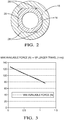
Figure 2 is a cross section, taken along a plane 2-2 perpendicular to the longitudinal axis of the valve needle of the injector inFigure 1 , to illustrate a guide for the valve needle of the injector; -
Figure 3 is a graph to illustrate the maximum available force available from the plunger as a function of plunger travel for the fuel injector inFigure 1 ; -
Figure 4 is a graph to illustrate the required force to lift the valve needle from a valve needle seating as a function of the gap between magnetic parts of the actuator, for three different fuel pressure levels; -
Figure 5 is a graph to illustrate a 'safe area' for dimensions of the injector show inFigure 1 operating at a first pressure level; -
Figure 6 is a graph to show the valve needle seat diameter as a function of the travel of the plunger to illustrate a 'safe area' for the injector dimensions; and -
Figure 7 is a graph to illustrate the 'safe area' of working for dimensions of the injector show inFigure 1 operating at a second pressure level that is different to the first pressure level ofFigure 5 . - For the purpose of the following description it will be appreciated that references to upper, lower, upward, downward, above and below, for example, are not intended to be limiting and relate only to the orientation of the injector as shown in the illustration.
- The present invention relates to a
fuel injector 10 of the type generally shown inFigure 1 . Theinjector 10 is suitable for use in a fuel injection system of an internal combustion engine, and particularly a diesel engine in which fuel is typically injected into the engine at high pressure levels in excess of 2000 bar, and commonly as high as 3000 bar. - The
injector 10 includes aninjection nozzle 12 at its lower end including avalve needle 14 which is slidable within ablind bore 16 provided in aninjection nozzle housing 18 under the influence of an actuator, referred to generally as 20, which also forms a part of the injector. Thevalve needle 14 is engageable with a valve needle seating (not identified), defined at the blind end of thebore 16, to control the flow of fuel from the injector into a combustion chamber of the engine. Fuel under high pressure is delivered to aninternal injector volume 22 defined within thebore 16 through a high pressure supply passage (to be described later). Theinternal injector volume 22 includes anupper region 22a of enlarged diameter. - The
injection nozzle housing 18 includes alower region 18a of reduced diameter compared to a mid-region 18b of the injection nozzle housing of enlarged diameter, with anintermediate region 18c of the nozzle housing, of intermediate diameter, separating the tworegions upper region 18d of theinjection nozzle housing 18 is of still further enlarged diameter compared to themid region 18c. Finally, a top region 18e of the injection nozzle housing forms a small upstand on top of theupper region 18d. Thelower region 18a of the injection nozzle housing is provided with a plurality of outlets (not shown) downstream of the valve needle seating to permit a flow of fuel from theinternal injector volume 22 into the combustion chamber when thevalve needle 14 is unseated. - The
valve needle 14 is of relatively short length and includes alower tip region 14a of a relatively small diameter which seats against the valve needle seating. The valve needle seating has a diameter Dseat and an equivalent surface area taken through a plane perpendicular to the longitudinal valve needle axis of SDseat. Anupper region 14b of the valve needle is of relatively large diameter compared to thelower tip region 14a. Theupper region 14b of the valve needle has a first diameter Dnoz and defines anupper end surface 14c having a surface area SDnoz. Between thetip region 14a and theupper region 14b of the valve needle, the valve needle is provided with a thrust surface which experiences an upwardly directed force, tending to urge the valve needle away from the valve needle seating, due to the surrounding fuel pressure within alower chamber 24 defined within thebore 16. - Referring also to
Figure 2 , anannular guide member 26 is located within thebore 16 and provides a guiding function for theupper region 14b of the valve needle as is moves towards and away from the valve needle seating. Theguide member 26 is of uniform diameter and the internal surface of thebore 16, in the region of the guide member, is provided with a plurality offlats 28 to permit fuel to flow between theinternal injector volume 22 and thelower chamber 24, past theguide member 26, and onwards to the outlets when the valve needle is unseated. - A
plunger 30 is also received within thebore 16 and is positioned above thevalve needle 14. Theplunger 30 is spaced apart from theupper surface 14c of thevalve needle 14 to define a space therebetween which defines achamber 31 for receiving fuel. The chamber is located in a region of theinjection nozzle housing 18 that is relatively close to the valve needle seating and resides within the reduced diameter region of the nozzle housing (i.e. thelower region 18a). Theplunger 30 includes alower region 30a of relatively long length and relatively small diameter, with a first diameter Dpc, compared to anupper region 30b of relatively large length and relatively large (second) diameter. A thrust surface of the plunger, between the upper andlower regions plunger 30 away from the valve needle seating, due to fuel pressure within theinternal injector volume 22. The diameter of the plunger, Dpc, is smaller than the diameter of theupper surface 14c of the valve needle, Dnoz. Of significance is the surface area of the end of the plunger, SDpc, at its lower end, compared to the surface area of theupper surface 14c of the valve needle, SDnoz, as will be described in further detail below. - Towards its upper end, the
plunger 30 carries alower spring seat 32, which resides in theenlarged chamber region 22a of theinternal injector volume 22. Thelower spring seat 32 is of annular form and defines an abutment surface for aspring 36 which tends to urge thevalve needle 14 towards the valve needle seating. An upperspring seat component 34 in the form of a sleeve is received within an upper region of theenlarged chamber region 22a. The upperspring seat component 34 is shaped to define aguide portion 34a for theupper region 30b of the plunger and also an abutment surface for the upper end of thespring 36, together with a tubular portion which is fixed within the top of theenlarged chamber 22a. The guide portion is shaped to define a clearance with the plunger which provides a flow path for fuel. Theguide portion 34a is defined by an annular flange or upstand provided at the lower end of thespring seat component 34. - The
electromagnetic actuator arrangement 20 provided at the upper end of the injector serves to actuate plunger movement and, consequently, movement of thevalve needle 14. Theactuator 20 is housed partly within the lowerinjection nozzle housing 18 and partly within an upperinjection nozzle housing 38. Theactuator 20 includes a firstmagnetic piece 40 which resides within theupper spring seat 34 and is spaced, by a fuel-filledgap 42, from a secondmagnetic piece 44 upstream of the firstmagnetic piece 40. The firstmagnetic piece 40 is attached to the upper end of theplunger 30 and includes anangled drilling 46. The secondmagnetic piece 44 is fixed within the upperinjection nozzle housing 38 and is provided with avertical drilling 48. Together with thegap 42 and theangled drilling 46, thevertical drilling 48 defines a flow path for high pressure fuel flowing into the injector from a high pressure fuel supply (e.g. a common rail) into theenlarged chamber region 22 of theinternal injector volume 22 and downstream towards thevalve needle 14. - The lower surface of the upper
injection nozzle housing 38 and the upper surface of the lowerinjection nozzle housing 18 are both of stepped form to define a region therebetween for housing a solenoid coil or winding 50 which forms a part of theactuator 20. Radially inward of the winding 50, an annular non-magnetic piece orring 52 is also housed in this region. The annularnon-magnetic piece 52 closes thegap 42 at its radially outer edge to prevent fuel leakage. - The lower
injection nozzle housing 18, theupper housing 38 and the actuator are housed within acap nut 54 to retain the parts securely in position relative to one another. - In operation of the injector, valve needle movement is controlled by controlling the current that is applied to the winding 50 of the
actuator 20. When a current is applied to the winding 50, an electromagnetic field is generated which attracts the firstmagnetic piece 40 towards the secondmagnetic piece 44, and therefore pulls the firstmagnetic piece 40 upwards, pulling theplunger 30 with it against the force of thespring 36. As theplunger 30 is pulled upwardly the volume of thechamber 31 between the lower end of theplunger 30 and theupper surface 14c of thevalve needle 14 is increased so that the pressure of fuel within thechamber 30 decreases. As a result, the downward force acting on theupper surface 14c of thevalve needle 14 is reduced and thevalve needle 14 starts to lift. The force of theplunger 30 is amplified by fuel pressure within thechamber 31 due to the different ratios of the lower end of theplunger 30 and theupper end surface 14c of thevalve needle 14, with an amplification factor determined by the ratio of SDpc to SDnoz. Once thevalve needle 14 has lifted away from the valve needle seating, fuel that is delivered to thelower chamber 24 is able to flow out through the outlets into the combustion chamber. The presence of the hydraulic amplifier means that, even for a relatively low force actuator, enough force can be transmitted to thevalve needle 14 to lift thevalve needle 14 from its seating. - When it is required to terminate injection, the current applied to the winding is removed, thereby reducing the force applied to the
plunger 30. As a result, the plunger is caused to move downwards, under the influence of thespring 36, reducing the volume of thechamber 31 between the end of theplunger 30 and thevalve needle 14 and causing fuel to be increased in thechamber 31. The increased fuel pressure in thechamber 31 results in an increased force being applied to thevalve needle 14 which overcomes the upwardly directed forces acting on the thrust surface of the valve needle and causes thevalve needle 14 to be seated, terminating injection through the outlets. - By controlling the current that is applied to the winding, injection can therefore be controlled to deliver single or multiple injections of fuel with accurate and precise timing.
- In selecting appropriate dimensions for the components of any injector there are many different factors to consider, not all of which are readily compatible with one another. These factors include, but are not limited to, the space available within the envelope of the injector to house all the components of the injector, the requirement for a relatively low mass of the moving components (e.g. the
valve needle 14 and the plunger 30), which affects the response time, the requirement for the injector to store a relatively large fuel volume of fuel to be injected (e.g. theinternal injector volume 22 and the volume of theenlarged chamber 22a), the balance of forces on thevalve needle 14 between the downward forces tending to seat thevalve needle 14 and the upward forces tending to unseat the valve needle 14 (e.g. due to fuel pressure acting on the upwardly-directed thrust surfaces), the force capability of theactuator 20, and the requirement for a satisfactory flow rate through the valve needle outlets when injecting. In addition, there is a limit on the minimum diameter of the valve needle seating, which must be large enough to create a proper seat condition for the differential angle at the seat, and so as to minimise the effects of seat migration, and also considering the requirement for the outlets to be machined downstream of the seating. All these considerations make the act of optimising the injector design a difficult and challenging task. - As a consequence of these considerations, the inventor has invented a convenient and accurate methodology for determining the optimum dimensions for an injector generally of the type shown in
Figure 1 i.e. an injector with avalve needle 14 and aplunger 30 coupled through a hydraulic amplifier, with theplunger 30 being operable by means of anelectromagnetic actuator 20 to move thevalve needle 14. - For an
electromagnetic actuator 20 such as that shown inFigure 1 , the magnetic force, F, that can be exerted on theplunger 30 is given by:
gap 42 between the first and secondmagnetic pieces gap 42 and µ0 is the fluid permeability in the gap. If the first and secondmagnetic pieces actuator 20, which is applied to theplunger 30 directly. The diameter of the plunger bore 16 may be around 9 mm and the plunger diameter, Dpc, does not exceed 8 mm to minimise the overall injector size. This gives a relatively largeinternal volume 22 for receiving and storing fuel within the injector. -
Figure 2 is a graph to illustrate the maximum available plunger force (in Newtons) as a function of plunger travel (i.e. the maximum range of movement of the plunger in millimetres) for a plunger having a diameter of 8mm and a saturation induction, B, in thegap 42 of 2.3 Teslas (T). It can be seen from the graph that as the plunger travel increases, the maximum available force that is available to be applied to theplunger 30 is reduced, in a linear relationship with plunger travel. This places a limit on the maximum possible extent of plunger travel for any given actuator and force capability. - In constructing the injector it is also necessary to consider the force requirement to lift the
valve needle 14 against the forces tending to seat thevalve needle 14, bearing in mind the high fuel pressures (typically 2500-3000 bar) that are present in theinternal injector volume 22 which tend to act in this direction.Figure 4 illustrates the force required to lift thevalve needle 14 for three different fuel pressure levels, and illustrates that the force requirement increases as the fuel pressure increases. Reducing the seat diameter, Dseat, reduces the force requirement to lift the valve needle, but the hydraulic amplification is essential to provide an adequate lift force to thevalve needle 14, as provided by the arrangement of theplunger 30, thechamber 31 and the valve needle inFigure 1 . Incorporating a hydraulic amplifier between theplunger 30 and thevalve needle 14 provides the necessary 'boost' to the force from theactuator 20 that is transmitted to theplunger 30, and hence to thevalve needle 14, with the force on thevalve needle 14 being proportional to the ratio of the surface area of the lower end of the plunger that acts on fuel within thechamber 31 relative to the surface area of theupper surface 14c of the valve needle that is exposed to fuel within the chamber 31 (i.e. SDnoz/SDpc). - It has been identified that a minimum seat diameter of around 0.9mm marks a threshold for a safe and reliable valve needle seating area given the flow requirements through the
valve needle 14 when injecting. This also prevents undesirable pressure loss in the sac region immediately downstream of the valve needle tip when the flow reaches the injection nozzle outlets, and ensures that the force versus lift requirements are satisfied, particularly for pilot injections.Figure 3 shows a graph to illustrate the ratio SDnoz/SDseat as a function of SDnoz/SDpc, and from where a 'safe area' of operation can be identified within which thevalve needle 14 can be lifted, the flow requirement through the valve needle outlets is satisfied, and the gap between the first and secondmagnetic pieces plunger 30. In identifying this 'safe area' (identified at 64) on the graph ofFigure 5 , the inventor has realised that it is possible to establish a set of rules for dimensioning the injector so as to operate effectively. - For an injector operating at 3000bar, the limits of the safe working area of the graph in
Figure 5 can be defined by the following equation:

Figure 5 which delimit the safe area of operation. - In addition, the ratio SDnoz/SDpc can be defined by:

- It follows from these two limitations that:

- In addition, due to seat dimension limitation and the plunger travel safe working area, an additional relationship can be established by considering the seat diameter, Dseat, as a function of the plunger travel, as shown in
Figure 6 . - The 'safe area' of operation in
Figure 6 can be represented by the following relationship;

PLimit 2 is 1.20mm. - These limits derive from the upper and lower boundary lines, 70 and 72 respectively, of the 'safe area' of the graph identified at 74 in
Figure 6 . - By adhering to the abovementioned rules for injector set-up, an effective and well-performing injector can be realised.
- For injector operation at a different pressure for example 2500 bar, the safe area of working for the injector is shifted.
Figure 7 shows the ratio SDnoz/SDseat as a function of SDnoz/SDpc for an injector of the type shown inFigure 1 operating at a pressure level of around 2500bar. Theupper limit 80 of thesafe area 82 is substantially the same as theupper boundary 70 inFigure 6 for the injector when operating at 3000bar. This is because the upper boundary is determined by the minimum seat diameter which can be safely achieved, regardless of any other variation in injector dimensions. However, thelower limit 84 of thesafe area 82 inFigure 7 has shifted downwards and so the following limitations apply:
- In other words, Factor2 is 1.73333, Offset2 is 1.0, Factor1 is 1.4666 and Offset1 is 4.6.
- The optimum values for the multiplication factor, Factor1, and the offset valve, Offset1, of the upper boundary limit are therefore independent of the operating pressure for the fuel injector, whereas the optimum value for the multiplication factor, Factor2, and the offset value, Offset2, of the lower boundary limit are dependent on the fuel pressure. Typically, for example, the multiplication factors and the offset values (Factor1 and Offset1) for the upper boundary limit, may be between plus or minus 10 % of the values stated above, regardless of the fuel pressure at which the injector operates, and more preferably within plus or minus 5% of the stated values, to ensure optimum injector functioning at that fuel pressure, considering all of the aforementioned requirements and considerations.
- Where reference is made to a value being "approximate", it is intended that the value referred to need not be exact but should approximate within a reasonable deviation to that value, typically no more than a 10% deviation from the stated value.
- It will be appreciated that many modifications may be made to the above examples without departing from the scope of the present invention as defined in the accompanying claims.
Claims (14)
- A direct acting fuel injector (10) for use in an internal combustion engine, the fuel injector comprising:an actuator (20);a hydraulic amplifier chamber (31) for fuel;a valve needle (14) having an upper end (14b) with a first diameter (Dnoz) and a related surface area (SDnoz) which is exposed to fuel within the hydraulic amplifier chamber (31), the valve needle (14) being movable towards and away from a valve needle seating to control the delivery of fuel through an injector outlet, wherein the valve needle seating has a seat diameter (Dseat) and a related surface area (SDseat); anda plunger (30) having a second diameter (Dpc) and a related surface area (SDpc) exposed to fuel within the hydraulic amplifier chamber 931), the plunger (31) being actuable by means of the actuator (20) to provide a force to the valve needle (14) with an amplification factor determined by the ratio of the second diameter (Dpc) to the first diameter (Dnoz);wherein SDnoz, SDseat and SDpc are selected such that they fall within a safe area which upper boundary (60; 80) is defined by the equation:


- The fuel injector as claimed in claim 1, wherein the lower boundary (62; 84) of the safe area is defined by [(SDNoz/SDpc x Factor2) + Offset2], wherein Factor2 and Offset2 are dependent on the fuel pressure at which the injector (10) is operating.
- The fuel injector as claimed in claim 2, wherein for operation at a fuel pressure of between 2500bar and 3000bar, Factor2 being between 1.1 and 1.9 , and Offset2 is between 0.9 and 4.7.
- The fuel injector as claimed in claim 3, wherein for operation at a fuel pressure of approximately 3000bar, Factor2 is between 1.1 and 4.7.
- The fuel injector as claimed in claim 4, wherein for operation at a fuel pressure of approximately 3000bar, Factor2 is between 1.15 and 4.5.
- The fuel injector as claimed in claim 3, wherein for operation at a fuel pressure of approximately 2500bar, Factor2 is between 1.55 and 1.90 and Offset2 is between 0.9 and 1.1.
- The fuel injector as claimed in any of claims 1 to 6, wherein for operation at a fuel pressure of between 2500bar and 3000bar, Factor1 is between 1.30 and 1.60 and Offset1 is between 4.2 and 5.1.
- The fuel injector as claimed in claim 7, wherein for operation at a fuel pressure of between 2500bar and 3000bar, Factor1 is between 1.38 and 1.55 and Offset1 is between 4.37 and 4.83.
- The fuel injector as claimed in any of claims 1 to 8, wherein the plunger (30) is configured to have a range of travel (Ptravel) such that:


- The fuel injector as claimed in claim 9, wherein PLimit1 is between 1.02 and 1.19 and PLimit2 is between 1.14 and 1.26.
- The fuel injector as claimed in claim 9 or claim 10, wherein Factor3 is between 0.17 and 0.29 and Offset3 is between 0.71 and 0.78.
- The fuel injector as claimed in any of claims 1 to 11, wherein the seat diameter (Dseat) is selected so as to be no less than 0.9 mm.
- The fuel injector as claimed in any of claims 1 to 12, wherein SDnoz and SDpc are further selected such that they satisfy Limit1 < SDnoz/SDpc < Limit2, where Limit1 is between 2.7 and 3.3 and Limit2 is between 3.4 and 4.1.
- The fuel injector as claimed in any of claims 1 to 13, wherein the actuator is an electromagnetic actuator (20).
Applications Claiming Priority (1)
| Application Number | Priority Date | Filing Date | Title |
|---|---|---|---|
| GBGB1520123.9A GB201520123D0 (en) | 2015-11-16 | 2015-11-16 | Fuel injector |
Publications (1)
| Publication Number | Publication Date |
|---|---|
| EP3168452A1 true EP3168452A1 (en) | 2017-05-17 |
Family
ID=55132807
Family Applications (1)
| Application Number | Title | Priority Date | Filing Date |
|---|---|---|---|
| EP16198728.4A Withdrawn EP3168452A1 (en) | 2015-11-16 | 2016-11-14 | Fuel injector |
Country Status (2)
| Country | Link |
|---|---|
| EP (1) | EP3168452A1 (en) |
| GB (1) | GB201520123D0 (en) |
Cited By (1)
| Publication number | Priority date | Publication date | Assignee | Title |
|---|---|---|---|---|
| CN113795665A (en) * | 2019-05-16 | 2021-12-14 | 卡特彼勒公司 | Fuel system with fixed geometry flow control valve for limiting injector cross talk |
Citations (4)
| Publication number | Priority date | Publication date | Assignee | Title |
|---|---|---|---|---|
| EP2386746A2 (en) * | 2010-05-11 | 2011-11-16 | Robert Bosch GmbH | Fuel injector |
| DE102012222127A1 (en) * | 2012-12-04 | 2014-06-05 | Robert Bosch Gmbh | Fuel injector for injecting fuel into combustion chamber of internal combustion engine, has hydraulic coupler that is comprised of pair of coupler piston for separating two couplers |
| DE102012222043A1 (en) * | 2012-12-03 | 2014-06-05 | Robert Bosch Gmbh | Fuel injector for injecting fuel into combustion chamber of internal combustion engine, has coupler piston whose active faces limit hydraulic coupler in axial direction |
| DE102013210744A1 (en) * | 2013-06-10 | 2014-12-11 | Robert Bosch Gmbh | fuel injector |
-
2015
- 2015-11-16 GB GBGB1520123.9A patent/GB201520123D0/en not_active Ceased
-
2016
- 2016-11-14 EP EP16198728.4A patent/EP3168452A1/en not_active Withdrawn
Patent Citations (4)
| Publication number | Priority date | Publication date | Assignee | Title |
|---|---|---|---|---|
| EP2386746A2 (en) * | 2010-05-11 | 2011-11-16 | Robert Bosch GmbH | Fuel injector |
| DE102012222043A1 (en) * | 2012-12-03 | 2014-06-05 | Robert Bosch Gmbh | Fuel injector for injecting fuel into combustion chamber of internal combustion engine, has coupler piston whose active faces limit hydraulic coupler in axial direction |
| DE102012222127A1 (en) * | 2012-12-04 | 2014-06-05 | Robert Bosch Gmbh | Fuel injector for injecting fuel into combustion chamber of internal combustion engine, has hydraulic coupler that is comprised of pair of coupler piston for separating two couplers |
| DE102013210744A1 (en) * | 2013-06-10 | 2014-12-11 | Robert Bosch Gmbh | fuel injector |
Cited By (1)
| Publication number | Priority date | Publication date | Assignee | Title |
|---|---|---|---|---|
| CN113795665A (en) * | 2019-05-16 | 2021-12-14 | 卡特彼勒公司 | Fuel system with fixed geometry flow control valve for limiting injector cross talk |
Also Published As
| Publication number | Publication date |
|---|---|
| GB201520123D0 (en) | 2015-12-30 |
Similar Documents
| Publication | Publication Date | Title |
|---|---|---|
| EP0195736B1 (en) | Accumulator injector | |
| JP2576861B2 (en) | Fuel injection device for internal combustion engine | |
| US5860597A (en) | Injection rate shaping nozzle assembly for a fuel injector | |
| EP2273097B1 (en) | Fuel Injector | |
| EP0798459A2 (en) | Injection nozzle | |
| EP0767304A1 (en) | Injector | |
| US7156368B2 (en) | Solenoid actuated flow controller valve | |
| EP1053397B1 (en) | Hydraulically actuated fuel injector with seated pin actuator | |
| EP2604848B1 (en) | Fuel injector | |
| JPS6154945B2 (en) | ||
| US6425368B1 (en) | Fuel injector | |
| EP0844383B1 (en) | Injector | |
| EP0921302A2 (en) | Fuel injector | |
| US6209805B1 (en) | Fuel injector | |
| US6595188B2 (en) | Compact valve assembly and fuel injector using same | |
| EP3004625B1 (en) | Control valve for a fuel injector | |
| DE10007735A1 (en) | Fuel injection valve for IC engines has pressure-reducing throttle between high-pressure fuel in fuel chamber/line and lower pressure fuel in valve needle actuator area | |
| CN108291508B (en) | fuel injector | |
| JP2018003789A (en) | Fuel injection valve and common rail injection system | |
| EP2083165A1 (en) | Injection nozzle | |
| JP3303565B2 (en) | Fuel injection device | |
| EP2647826B1 (en) | Valve arrangement | |
| US10337478B2 (en) | Fuel injector | |
| JPS6022050A (en) | Fuel injection apparatus | |
| US20180156176A1 (en) | High pressure valve |
Legal Events
| Date | Code | Title | Description |
|---|---|---|---|
| PUAI | Public reference made under article 153(3) epc to a published international application that has entered the european phase |
Free format text: ORIGINAL CODE: 0009012 |
|
| AK | Designated contracting states |
Kind code of ref document: A1 Designated state(s): AL AT BE BG CH CY CZ DE DK EE ES FI FR GB GR HR HU IE IS IT LI LT LU LV MC MK MT NL NO PL PT RO RS SE SI SK SM TR |
|
| AX | Request for extension of the european patent |
Extension state: BA ME |
|
| 17P | Request for examination filed |
Effective date: 20171117 |
|
| RBV | Designated contracting states (corrected) |
Designated state(s): AL AT BE BG CH CY CZ DE DK EE ES FI FR GB GR HR HU IE IS IT LI LT LU LV MC MK MT NL NO PL PT RO RS SE SI SK SM TR |
|
| 17Q | First examination report despatched |
Effective date: 20181127 |
|
| RAP1 | Party data changed (applicant data changed or rights of an application transferred) |
Owner name: DELPHI TECHNOLOGIES IP LIMITED |
|
| STAA | Information on the status of an ep patent application or granted ep patent |
Free format text: STATUS: THE APPLICATION IS DEEMED TO BE WITHDRAWN |
|
| 18D | Application deemed to be withdrawn |
Effective date: 20190409 |