EP3168440A1 - Mixing structure - Google Patents
Mixing structure Download PDFInfo
- Publication number
- EP3168440A1 EP3168440A1 EP15796811.6A EP15796811A EP3168440A1 EP 3168440 A1 EP3168440 A1 EP 3168440A1 EP 15796811 A EP15796811 A EP 15796811A EP 3168440 A1 EP3168440 A1 EP 3168440A1
- Authority
- EP
- European Patent Office
- Prior art keywords
- exhaust gas
- lattice board
- injector
- flow
- additive
- Prior art date
- Legal status (The legal status is an assumption and is not a legal conclusion. Google has not performed a legal analysis and makes no representation as to the accuracy of the status listed.)
- Granted
Links
Images


Classifications
-
- F—MECHANICAL ENGINEERING; LIGHTING; HEATING; WEAPONS; BLASTING
- F01—MACHINES OR ENGINES IN GENERAL; ENGINE PLANTS IN GENERAL; STEAM ENGINES
- F01N—GAS-FLOW SILENCERS OR EXHAUST APPARATUS FOR MACHINES OR ENGINES IN GENERAL; GAS-FLOW SILENCERS OR EXHAUST APPARATUS FOR INTERNAL-COMBUSTION ENGINES
- F01N3/00—Exhaust or silencing apparatus having means for purifying, rendering innocuous, or otherwise treating exhaust
- F01N3/08—Exhaust or silencing apparatus having means for purifying, rendering innocuous, or otherwise treating exhaust for rendering innocuous
- F01N3/10—Exhaust or silencing apparatus having means for purifying, rendering innocuous, or otherwise treating exhaust for rendering innocuous by thermal or catalytic conversion of noxious components of exhaust
- F01N3/24—Exhaust or silencing apparatus having means for purifying, rendering innocuous, or otherwise treating exhaust for rendering innocuous by thermal or catalytic conversion of noxious components of exhaust characterised by constructional aspects of converting apparatus
- F01N3/28—Construction of catalytic reactors
- F01N3/2892—Exhaust flow directors or the like, e.g. upstream of catalytic device
-
- B—PERFORMING OPERATIONS; TRANSPORTING
- B01—PHYSICAL OR CHEMICAL PROCESSES OR APPARATUS IN GENERAL
- B01F—MIXING, e.g. DISSOLVING, EMULSIFYING OR DISPERSING
- B01F23/00—Mixing according to the phases to be mixed, e.g. dispersing or emulsifying
- B01F23/20—Mixing gases with liquids
- B01F23/21—Mixing gases with liquids by introducing liquids into gaseous media
- B01F23/213—Mixing gases with liquids by introducing liquids into gaseous media by spraying or atomising of the liquids
- B01F23/2132—Mixing gases with liquids by introducing liquids into gaseous media by spraying or atomising of the liquids using nozzles
-
- B—PERFORMING OPERATIONS; TRANSPORTING
- B01—PHYSICAL OR CHEMICAL PROCESSES OR APPARATUS IN GENERAL
- B01F—MIXING, e.g. DISSOLVING, EMULSIFYING OR DISPERSING
- B01F25/00—Flow mixers; Mixers for falling materials, e.g. solid particles
- B01F25/30—Injector mixers
- B01F25/31—Injector mixers in conduits or tubes through which the main component flows
- B01F25/313—Injector mixers in conduits or tubes through which the main component flows wherein additional components are introduced in the centre of the conduit
- B01F25/3131—Injector mixers in conduits or tubes through which the main component flows wherein additional components are introduced in the centre of the conduit with additional mixing means other than injector mixers, e.g. screens, baffles or rotating elements
-
- B—PERFORMING OPERATIONS; TRANSPORTING
- B01—PHYSICAL OR CHEMICAL PROCESSES OR APPARATUS IN GENERAL
- B01F—MIXING, e.g. DISSOLVING, EMULSIFYING OR DISPERSING
- B01F25/00—Flow mixers; Mixers for falling materials, e.g. solid particles
- B01F25/30—Injector mixers
- B01F25/31—Injector mixers in conduits or tubes through which the main component flows
- B01F25/314—Injector mixers in conduits or tubes through which the main component flows wherein additional components are introduced at the circumference of the conduit
- B01F25/3141—Injector mixers in conduits or tubes through which the main component flows wherein additional components are introduced at the circumference of the conduit with additional mixing means other than injector mixers
-
- B—PERFORMING OPERATIONS; TRANSPORTING
- B01—PHYSICAL OR CHEMICAL PROCESSES OR APPARATUS IN GENERAL
- B01F—MIXING, e.g. DISSOLVING, EMULSIFYING OR DISPERSING
- B01F25/00—Flow mixers; Mixers for falling materials, e.g. solid particles
- B01F25/40—Static mixers
- B01F25/42—Static mixers in which the mixing is affected by moving the components jointly in changing directions, e.g. in tubes provided with baffles or obstructions
- B01F25/43—Mixing tubes, e.g. wherein the material is moved in a radial or partly reversed direction
- B01F25/431—Straight mixing tubes with baffles or obstructions that do not cause substantial pressure drop; Baffles therefor
- B01F25/4315—Straight mixing tubes with baffles or obstructions that do not cause substantial pressure drop; Baffles therefor the baffles being deformed flat pieces of material
-
- F—MECHANICAL ENGINEERING; LIGHTING; HEATING; WEAPONS; BLASTING
- F01—MACHINES OR ENGINES IN GENERAL; ENGINE PLANTS IN GENERAL; STEAM ENGINES
- F01N—GAS-FLOW SILENCERS OR EXHAUST APPARATUS FOR MACHINES OR ENGINES IN GENERAL; GAS-FLOW SILENCERS OR EXHAUST APPARATUS FOR INTERNAL-COMBUSTION ENGINES
- F01N3/00—Exhaust or silencing apparatus having means for purifying, rendering innocuous, or otherwise treating exhaust
- F01N3/08—Exhaust or silencing apparatus having means for purifying, rendering innocuous, or otherwise treating exhaust for rendering innocuous
- F01N3/10—Exhaust or silencing apparatus having means for purifying, rendering innocuous, or otherwise treating exhaust for rendering innocuous by thermal or catalytic conversion of noxious components of exhaust
- F01N3/18—Exhaust or silencing apparatus having means for purifying, rendering innocuous, or otherwise treating exhaust for rendering innocuous by thermal or catalytic conversion of noxious components of exhaust characterised by methods of operation; Control
- F01N3/20—Exhaust or silencing apparatus having means for purifying, rendering innocuous, or otherwise treating exhaust for rendering innocuous by thermal or catalytic conversion of noxious components of exhaust characterised by methods of operation; Control specially adapted for catalytic conversion
- F01N3/206—Adding periodically or continuously substances to exhaust gases for promoting purification, e.g. catalytic material in liquid form, NOx reducing agents
- F01N3/2066—Selective catalytic reduction [SCR]
-
- B—PERFORMING OPERATIONS; TRANSPORTING
- B01—PHYSICAL OR CHEMICAL PROCESSES OR APPARATUS IN GENERAL
- B01F—MIXING, e.g. DISSOLVING, EMULSIFYING OR DISPERSING
- B01F25/00—Flow mixers; Mixers for falling materials, e.g. solid particles
- B01F2025/93—Arrangements, nature or configuration of flow guiding elements
- B01F2025/931—Flow guiding elements surrounding feed openings, e.g. jet nozzles
-
- F—MECHANICAL ENGINEERING; LIGHTING; HEATING; WEAPONS; BLASTING
- F01—MACHINES OR ENGINES IN GENERAL; ENGINE PLANTS IN GENERAL; STEAM ENGINES
- F01N—GAS-FLOW SILENCERS OR EXHAUST APPARATUS FOR MACHINES OR ENGINES IN GENERAL; GAS-FLOW SILENCERS OR EXHAUST APPARATUS FOR INTERNAL-COMBUSTION ENGINES
- F01N2240/00—Combination or association of two or more different exhaust treating devices, or of at least one such device with an auxiliary device, not covered by indexing codes F01N2230/00 or F01N2250/00, one of the devices being
- F01N2240/20—Combination or association of two or more different exhaust treating devices, or of at least one such device with an auxiliary device, not covered by indexing codes F01N2230/00 or F01N2250/00, one of the devices being a flow director or deflector
-
- F—MECHANICAL ENGINEERING; LIGHTING; HEATING; WEAPONS; BLASTING
- F01—MACHINES OR ENGINES IN GENERAL; ENGINE PLANTS IN GENERAL; STEAM ENGINES
- F01N—GAS-FLOW SILENCERS OR EXHAUST APPARATUS FOR MACHINES OR ENGINES IN GENERAL; GAS-FLOW SILENCERS OR EXHAUST APPARATUS FOR INTERNAL-COMBUSTION ENGINES
- F01N2610/00—Adding substances to exhaust gases
- F01N2610/02—Adding substances to exhaust gases the substance being ammonia or urea
-
- F—MECHANICAL ENGINEERING; LIGHTING; HEATING; WEAPONS; BLASTING
- F01—MACHINES OR ENGINES IN GENERAL; ENGINE PLANTS IN GENERAL; STEAM ENGINES
- F01N—GAS-FLOW SILENCERS OR EXHAUST APPARATUS FOR MACHINES OR ENGINES IN GENERAL; GAS-FLOW SILENCERS OR EXHAUST APPARATUS FOR INTERNAL-COMBUSTION ENGINES
- F01N2610/00—Adding substances to exhaust gases
- F01N2610/14—Arrangements for the supply of substances, e.g. conduits
- F01N2610/1453—Sprayers or atomisers; Arrangement thereof in the exhaust apparatus
-
- Y—GENERAL TAGGING OF NEW TECHNOLOGICAL DEVELOPMENTS; GENERAL TAGGING OF CROSS-SECTIONAL TECHNOLOGIES SPANNING OVER SEVERAL SECTIONS OF THE IPC; TECHNICAL SUBJECTS COVERED BY FORMER USPC CROSS-REFERENCE ART COLLECTIONS [XRACs] AND DIGESTS
- Y02—TECHNOLOGIES OR APPLICATIONS FOR MITIGATION OR ADAPTATION AGAINST CLIMATE CHANGE
- Y02T—CLIMATE CHANGE MITIGATION TECHNOLOGIES RELATED TO TRANSPORTATION
- Y02T10/00—Road transport of goods or passengers
- Y02T10/10—Internal combustion engine [ICE] based vehicles
- Y02T10/12—Improving ICE efficiencies
Definitions
- the present invention relates to a mixing structure for adding an additive halfway in an exhaust system to disperse the additive into exhaust gas while facilitating vaporization of the additive.
- some diesel engines have a selective reduction catalyst incorporated in an exhaust pipe through which exhaust gas flows, said catalyst having a feature of selectively reacting NO x (nitrogen oxides) with a reducing agent even in the presence of oxygen.
- NO x nitrogen oxides
- a required amount of reducing agent is added upstream of the reduction catalyst and is reductively reacted on the catalyst with NO x in the exhaust gas to thereby reduce a concentration of NO x discharged.
- the urea water added into the exhaust gas upstream of the selective reduction catalyst is thermally decomposed into ammonia and carbon dioxide gas according to the following formula to satisfactorily depurate NO x in the exhaust gas through reduction on the catalyst by the ammonia.
- Fig. 1 is an example of conventional art for addition of urea water into exhaust gas upstream of a selective reduction catalyst.
- an exhaust pipe 1 has an outer periphery formed with a bulge portion 2 protruding obliquely upstream.
- an injector 3 mounted on an upstream side of the bulge portion 2 is an injector 3 which is directed obliquely downstream to approach to an inside of the exhaust pipe 1 so as to add urea water 5 while protecting the injector 3 from being directly exposed to the flow of the hot exhaust gas 4.
- a lattice board 6 Arranged in the exhaust pipe 1 downstream of the added position of the urea water 5 by the injector 3 is a lattice board 6 on which hit is urea water 5 sprayed from the injector 3 for dispersion and facilitated vaporization of the urea water 5.
- the lattice board 6 is axially provided with a number of flow passages 6a.
- the flow passages 6a are provided, on their discharge sides, with alternately reversely directed fins 6b so that flows of the exhaust gas 4 discharged from the flow passages 6a are sorted alternately in reverse directions, which facilitates hitting and dispersion of the urea water 5 on the fins 6b and into the exhaust gas 4.
- Patent Literature 1 As conventional art document.
- Patent Literature 1 JP 2013-217350A
- the lattice board 6 is usually arranged in a selected one of straight portions in the exhaust pipe 1 such that the lattice board 6 is substantially at right angle to and blocks the selected straight portion from a viewpoint of efficiently increasing a temperature of a whole of the lattice board 6 by heat of the exhaust gas 4.
- straight portions in the exhaust pipe 1 are limitative in number so that it is often difficult to arrange the injector 3 in such straight portion while avoiding interference with peripheral devices and structures, disadvantageously resulting in a lower degree of freedom in layout of the injector 3 and lattice board 6.
- the spray of urea water 5 injected obliquely from the injector 3 to a downstream side in the flow of the exhaust gas 4 tends to be instantly accompanied with the flow of the exhaust gas 4 and pass through without contact with flow passage walls in the lattice board 6 extending in parallel with an inflow direction of the exhaust gas 4.
- any straight portion of the exhaust pipe 1 itself is inherently a portion extremely low in pressure loss; however, to arrange the lattice board 6 in the straight portion has an adverse effect of increasing the pressure loss.
- hitting of the exhaust gas flows on the fins 6b on the discharge sides of the flow passages 6a are continuously followed by hitting of the exhaust gas flows on an inner periphery of the exhaust pipe 1, resulting in still further increase in pressure loss.
- the invention was made in view of the above and has its object to provide a mixing structure which can enhance a degree of freedom in layout of an injector and a lattice board as well as evaporation efficiency of urea water or other additive while suppressing any pressure loss resulting from arranging the lattice board.
- the invention is directed to a mixing structure having a lattice board axially with a number of flow passages and arranged halfway in an exhaust system, an additive added upstream of the lattice board being hit on flow passage walls in said lattice board for dispersion and facilitated vaporization of the additive, said mixing structure comprising said lattice board arranged obliquely in a flow changing portion halfway in the exhaust system where the exhaust gas flows curvedly so as to substantially bisect an angle in said flow changing portion made by inflow and outflow directions of the exhaust gas from upstream of and discharged downstream of said flow changing portion, respectively, and an injector arranged to inject the additive in the outflow direction of said exhaust gas to an entry side of said lattice board such that the flow passage walls in said lattice board on which hit is the exhaust gas from upstream of said flow changing portion have rear surfaces on which hit is a spray of the additive from said injector.
- the lattice board to be arranged in a most suitable one selected among a number of flow changing portions existing halfway in the exhaust system, so that upon arranging the injector for addition of the additive upstream of the lattice board, interference of the injector with peripheral devices and structures can be easily averted, resulting in enhancing freedom in layout of the injector and lattice board to a degree unattainable in the conventional art.
- the spray of the additive becomes hardly affected by the flows of the exhaust gas and is easily hit on the flow passage walls in the lattice board.
- the flow passage walls on which hit is the additive have front surfaces effectively heated through hitting of the exhaust gas, so that vaporization of the sprayed additive is remarkably facilitated to enhance vaporization efficiency to a degree unattainable in the conventional art.
- the lattice board is arranged obliquely so as to substantially bisect the angle made by the inflow and outflow directions of the exhaust gas, so that any deviant flows of the exhaust gas outward of the curved direction can be remedied through straightening effect by the flow passages in the lattice board, whereby pressure loss can be reduced in comparison with a case without a lattice board.
- fins are arranged on the discharge sides of the flow passages in the lattice board to guide the flows of the exhaust gas to the outflow direction from the flow changing portion. This enables the flows of the exhaust gas discharged from the flow passages in the lattice board to be guided by the fins to the outflow direction, so that the straightening effect by the flow passages in the lattice board can be further enhanced to further reduce the pressure loss.
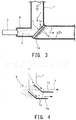
- Fig. 3 shows a first embodiment of the invention.
- a bent portion 1A a flow changing portion where exhaust gas 4 flows curvedly
- an exhaust pipe 1 an exhaust system
- a lattice board 7 so as to substantially bisect an angle made by inflow and outflow directions (see arrows x and y in Fig. 3 , respectively) of the exhaust gas 4 from upstream of and discharged downstream of the bent portion 1A, respectively.
- the lattice board 7 axially has a number of flow passages 7a provided, on discharge sides of the flow passages 7a, with fins 7b guiding the flows of the exhaust gas 4 to the outflow direction from the bent portion 1A, so that the straightening effect by the flow passages 7a and the fins 7b is afforded to the exhaust gas 4 flowing curvedly in the bent portion 1A.
- an injector 3 so as to inject urea water 5 (additive) in the outflow direction of the exhaust gas 4 to an entry side of the lattice board 7 such that, as shown in enlarged scale in Fig. 4 , the flow passage walls of the lattice board 7 on which hit is the exhaust gas 4 from upstream of the bent portion 1A has rear surfaces on which hit is the urea water 5 sprayed from the injector 3.
- the flow passage walls in the lattice board 7 on which hit is the exhaust gas 4 from upstream of the bent portion 1A has the rear surfaces on which hit is the spray of the urea water 5 from the injector 3, the spray of the urea water 5 becomes hardly affected by the flows of the exhaust gas 4 and is easily hit on the flow passage walls of the lattice board 7 and moreover the flow passage walls are effectively heated through the hitting of the exhaust gas 4 on the front surfaces of the walls.
- vaporization of the spray of the urea water 5 is substantially facilitated to enhance the vaporization efficiency to a degree unattainable in the conventional art.
- the lattice board 7 is obliquely arranged in the bent portion 1A inherently having increased pressure loss due to the exhaust gas 4 flowing curvedly so as to substantially bisect the angle made by the inflow and outflow directions of the exhaust gas 4 can remedy any deviant flows of the exhaust gas 4 outward of the curved direction through the straightening effect by the flow passages 7a in the lattice board 7 and thus can reduce the pressure loss in comparison with a case without a lattice board 7.
- the flow passages 7a have the fins 7b on their discharge sides to guide the flows of the exhaust gas 4 discharging from the flow passages 7a in the lattice board 7 to the outflow direction so that the straightening effect by the flow passages 7a in the lattice board 7 can be further enhanced to further reduce the pressure loss.
- a degree of freedom in layout of the injector 3 and lattice board 7 can be substantially enhanced in comparison with the conventional art; vaporization efficiency of the urea water 5 can be substantially enhanced in comparison with the conventional art; and further, any pressure loss due to arranging the lattice board 7 can be substantially suppressed through the straightening effect by the flow passages 7a and the fins 7b.
- Fig. 5 shows a second embodiment of the invention which is an example applied to a flow changing portion 10A arranged on a discharge side of a casing 10 having an exhaust-gas purifying member 9 such as a particulate filter or an exhaust purifying catalyst so as to extract the exhaust gas 4 to an exhaust pipe 1 perpendicular to an axis of the member 9.
- an exhaust-gas purifying member 9 such as a particulate filter or an exhaust purifying catalyst
- the flow changing portion 10A is in the form of a chamber on an discharge side of the casing 10, extends axially of the downstream exhaust pipe 1 and has an opening 11 through which the exhaust gas 4 having passed the exhaust-gas purifying member 9 enters and flows curvedly to the exhaust pipe 1.
- a lattice board 7 is obliquely arranged to substantially bisect an angle made by inflow and outflow directions of the exhaust gas 4 (see arrows x and y in Fig. 5 ) from the opening 11 and discharged to the downstream exhaust pipe 1, respectively.
- an injector 3 capable of injecting a spray of urea water 5 (additive) to an entry side of the lattice board 7 in the outflow direction of the exhaust gas 4 such that the flow passage walls in the lattice board 7 on which hit is the exhaust gas 4 from the opening 11 have rear surfaces on which hit is the spray of the urea water 5 from the injector 3 (see Fig. 4 ).
- the mixing structure according to the invention can be applied to obtain effects and advantages similar to those mentioned in the above with respect to the first embodiment.
- a mixing structure of the invention is not limited to the above embodiments and that various changes and modifications may be made without departing from the scope of the invention.
- the flow changing portion is not necessarily restricted to a bent portion halfway of the exhaust system.
- the additive used is not necessarily restricted to urea water.
- the invention may be combined with any catalyst other than a selective reduction catalyst or a particulate filter.
Landscapes
- Chemical & Material Sciences (AREA)
- Chemical Kinetics & Catalysis (AREA)
- Engineering & Computer Science (AREA)
- Health & Medical Sciences (AREA)
- Toxicology (AREA)
- Combustion & Propulsion (AREA)
- Mechanical Engineering (AREA)
- General Engineering & Computer Science (AREA)
- Dispersion Chemistry (AREA)
- Exhaust Gas After Treatment (AREA)
- Catalysts (AREA)
- Exhaust Gas Treatment By Means Of Catalyst (AREA)
Abstract
Description
- The present invention relates to a mixing structure for adding an additive halfway in an exhaust system to disperse the additive into exhaust gas while facilitating vaporization of the additive.
- Conventionally, some diesel engines have a selective reduction catalyst incorporated in an exhaust pipe through which exhaust gas flows, said catalyst having a feature of selectively reacting NOx (nitrogen oxides) with a reducing agent even in the presence of oxygen. A required amount of reducing agent is added upstream of the reduction catalyst and is reductively reacted on the catalyst with NOx in the exhaust gas to thereby reduce a concentration of NOx discharged.
- Meanwhile, effectiveness of ammonia (NH3) used as a reducing agent for reduction and purification of NOx is well known in a field of industrial flue gas denitration in a plant or the like. However, in a field of automobile where safety is hard to assure as to running with ammonia itself being loaded, it has been proposed to use nontoxic urea water as reducing agent.
- Specifically, the urea water added into the exhaust gas upstream of the selective reduction catalyst is thermally decomposed into ammonia and carbon dioxide gas according to the following formula to satisfactorily depurate NOx in the exhaust gas through reduction on the catalyst by the ammonia.
[Chemical Formula 1] (NH2)2CO + H2O → 2NH3 + CO2
-
Fig. 1 is an example of conventional art for addition of urea water into exhaust gas upstream of a selective reduction catalyst. In the example illustrated, anexhaust pipe 1 has an outer periphery formed with a bulge portion 2 protruding obliquely upstream. Mounted on an upstream side of the bulge portion 2 is aninjector 3 which is directed obliquely downstream to approach to an inside of theexhaust pipe 1 so as to addurea water 5 while protecting theinjector 3 from being directly exposed to the flow of thehot exhaust gas 4. - Arranged in the
exhaust pipe 1 downstream of the added position of theurea water 5 by theinjector 3 is alattice board 6 on which hit isurea water 5 sprayed from theinjector 3 for dispersion and facilitated vaporization of theurea water 5. As enlargedly shown inFig. 2 , thelattice board 6 is axially provided with a number offlow passages 6a. Theflow passages 6a are provided, on their discharge sides, with alternately reversely directedfins 6b so that flows of theexhaust gas 4 discharged from theflow passages 6a are sorted alternately in reverse directions, which facilitates hitting and dispersion of theurea water 5 on thefins 6b and into theexhaust gas 4. - With respect to this kind of mixing structure, there exists, for example, the following
Patent Literature 1 as conventional art document. - Patent Literature 1:
JP 2013-217350A - In the conventional mixing structure as mentioned in the above, the
lattice board 6 is usually arranged in a selected one of straight portions in theexhaust pipe 1 such that thelattice board 6 is substantially at right angle to and blocks the selected straight portion from a viewpoint of efficiently increasing a temperature of a whole of thelattice board 6 by heat of theexhaust gas 4. However, such straight portions in theexhaust pipe 1 are limitative in number so that it is often difficult to arrange theinjector 3 in such straight portion while avoiding interference with peripheral devices and structures, disadvantageously resulting in a lower degree of freedom in layout of theinjector 3 andlattice board 6. - Moreover, in the conventional mixing structure, the spray of
urea water 5 injected obliquely from theinjector 3 to a downstream side in the flow of theexhaust gas 4 tends to be instantly accompanied with the flow of theexhaust gas 4 and pass through without contact with flow passage walls in thelattice board 6 extending in parallel with an inflow direction of theexhaust gas 4. Thus, it has been desired to attain further enhancement of vaporization efficiency of theurea water 5. - Moreover, any straight portion of the
exhaust pipe 1 itself is inherently a portion extremely low in pressure loss; however, to arrange thelattice board 6 in the straight portion has an adverse effect of increasing the pressure loss. Specifically, in thelattice board 6 as shown inFigs. 1 and 2 , hitting of the exhaust gas flows on thefins 6b on the discharge sides of theflow passages 6a are continuously followed by hitting of the exhaust gas flows on an inner periphery of theexhaust pipe 1, resulting in still further increase in pressure loss. - The invention was made in view of the above and has its object to provide a mixing structure which can enhance a degree of freedom in layout of an injector and a lattice board as well as evaporation efficiency of urea water or other additive while suppressing any pressure loss resulting from arranging the lattice board.
- The invention is directed to a mixing structure having a lattice board axially with a number of flow passages and arranged halfway in an exhaust system, an additive added upstream of the lattice board being hit on flow passage walls in said lattice board for dispersion and facilitated vaporization of the additive, said mixing structure comprising said lattice board arranged obliquely in a flow changing portion halfway in the exhaust system where the exhaust gas flows curvedly so as to substantially bisect an angle in said flow changing portion made by inflow and outflow directions of the exhaust gas from upstream of and discharged downstream of said flow changing portion, respectively, and an injector arranged to inject the additive in the outflow direction of said exhaust gas to an entry side of said lattice board such that the flow passage walls in said lattice board on which hit is the exhaust gas from upstream of said flow changing portion have rear surfaces on which hit is a spray of the additive from said injector.
- This enables the lattice board to be arranged in a most suitable one selected among a number of flow changing portions existing halfway in the exhaust system, so that upon arranging the injector for addition of the additive upstream of the lattice board, interference of the injector with peripheral devices and structures can be easily averted, resulting in enhancing freedom in layout of the injector and lattice board to a degree unattainable in the conventional art.
- Since the flow passage walls in the lattice board on which hit is the exhaust gas from upstream of the flow changing portion have the rear surfaces on which hit is the spray of additive from the injector, the spray of the additive becomes hardly affected by the flows of the exhaust gas and is easily hit on the flow passage walls in the lattice board. Moreover, the flow passage walls on which hit is the additive have front surfaces effectively heated through hitting of the exhaust gas, so that vaporization of the sprayed additive is remarkably facilitated to enhance vaporization efficiency to a degree unattainable in the conventional art.
- Moreover, in the flow changing portion which inherently has increased pressure loss due to the exhaust gas flowing curvedly, the lattice board is arranged obliquely so as to substantially bisect the angle made by the inflow and outflow directions of the exhaust gas, so that any deviant flows of the exhaust gas outward of the curved direction can be remedied through straightening effect by the flow passages in the lattice board, whereby pressure loss can be reduced in comparison with a case without a lattice board.
- Further, it is preferable in the invention that fins are arranged on the discharge sides of the flow passages in the lattice board to guide the flows of the exhaust gas to the outflow direction from the flow changing portion. This enables the flows of the exhaust gas discharged from the flow passages in the lattice board to be guided by the fins to the outflow direction, so that the straightening effect by the flow passages in the lattice board can be further enhanced to further reduce the pressure loss.
- According to the above-mentioned mixing structure of the invention, various excellent effects as mentioned below can be obtained.
-
- (I) The lattice board is arranged obliquely in the flow changing portion halfway in the exhaust system where the exhaust gas flows curvedly so as to substantially bisect the angle made by the inflow and outflow directions of the exhaust gas from upstream and discharged downstream of the flow changing portion, respectively; and the injector is arranged to inject the additive in the outflow direction of the exhaust gas to the entry side of the lattice board such that the flow passage walls in the lattice board on which hit is the exhaust gas from upstream of the flow changing portion have rear surfaces on which hit is the sprayed additive from the injector. As a result, freedom in layout of the injector and the lattice board can be substantially enhanced to a degree unattainable in the conventional art, and vaporization efficiency of the urea water or other additive can be substantially enhanced to a degree unattained in the conventional art; and further, any pressure loss due to arranging the lattice board can be substantially suppressed.
- (II) The fins provided on the discharge sides of the flow passages in the lattice board can guide the flows of the exhaust gas to the outflow direction from the flow changing portion, so that the straightening effect by the flow passages in the lattice board can be further enhanced to further reduce the pressure loss.
-
-
Fig. 1 is a sectional view showing an example of a conventional mixing structure; -
Fig. 2 is a enlarged view showing particulars of flow passages in a lattice board inFig. 1 ; -
Fig. 3 is a sectional view showing a first embodiment of the invention; -
Fig. 4 is an enlarged view showing particulars of flow passages in a lattice board inFig. 3 ; and -
Fig. 5 is a sectional view showing a second embodiment of the invention. - Embodiments of the invention will be described in conjunction with the drawings.
-
Fig. 3 shows a first embodiment of the invention. In the embodiment illustrated, arranged obliquely in a bent portion 1A (a flow changing portion whereexhaust gas 4 flows curvedly) halfway in an exhaust pipe 1 (an exhaust system) is alattice board 7 so as to substantially bisect an angle made by inflow and outflow directions (see arrows x and y inFig. 3 , respectively) of theexhaust gas 4 from upstream of and discharged downstream of the bent portion 1A, respectively. - The
lattice board 7 axially has a number of flow passages 7a provided, on discharge sides of the flow passages 7a, withfins 7b guiding the flows of theexhaust gas 4 to the outflow direction from the bent portion 1A, so that the straightening effect by the flow passages 7a and thefins 7b is afforded to theexhaust gas 4 flowing curvedly in the bent portion 1A. - With respect to the lattice board 7A, arranged on an opposite side to the
exhaust pipe 1 extending downstream from the bent portion 1A and through a bulge portion 8 is aninjector 3 so as to inject urea water 5 (additive) in the outflow direction of theexhaust gas 4 to an entry side of thelattice board 7 such that, as shown in enlarged scale inFig. 4 , the flow passage walls of thelattice board 7 on which hit is theexhaust gas 4 from upstream of the bent portion 1A has rear surfaces on which hit is theurea water 5 sprayed from theinjector 3. - This enables selection of a most appropriate one among a number of bent portions 1A halfway in the
exhaust pipe 1 and arrangement of thelattice board 7 in the selected bent portion so that, upon positioning theinjector 3 for addition of theurea water 5 upstream of thelattice board 7, theinjector 3 can be easily prevented from being interfered with peripheral devices and structures and thus freedom in layout of theinjector 3 andlattice board 7 can be enhanced to a degree unattainable in the conventional art. - Further, since the flow passage walls in the
lattice board 7 on which hit is theexhaust gas 4 from upstream of the bent portion 1A has the rear surfaces on which hit is the spray of theurea water 5 from theinjector 3, the spray of theurea water 5 becomes hardly affected by the flows of theexhaust gas 4 and is easily hit on the flow passage walls of thelattice board 7 and moreover the flow passage walls are effectively heated through the hitting of theexhaust gas 4 on the front surfaces of the walls. As a result, vaporization of the spray of theurea water 5 is substantially facilitated to enhance the vaporization efficiency to a degree unattainable in the conventional art. - The fact that the
lattice board 7 is obliquely arranged in the bent portion 1A inherently having increased pressure loss due to theexhaust gas 4 flowing curvedly so as to substantially bisect the angle made by the inflow and outflow directions of theexhaust gas 4 can remedy any deviant flows of theexhaust gas 4 outward of the curved direction through the straightening effect by the flow passages 7a in thelattice board 7 and thus can reduce the pressure loss in comparison with a case without alattice board 7. - Especially, in the embodiment, the flow passages 7a have the
fins 7b on their discharge sides to guide the flows of theexhaust gas 4 discharging from the flow passages 7a in thelattice board 7 to the outflow direction so that the straightening effect by the flow passages 7a in thelattice board 7 can be further enhanced to further reduce the pressure loss. - Thus, according to the above embodiment, a degree of freedom in layout of the
injector 3 andlattice board 7 can be substantially enhanced in comparison with the conventional art; vaporization efficiency of theurea water 5 can be substantially enhanced in comparison with the conventional art; and further, any pressure loss due to arranging thelattice board 7 can be substantially suppressed through the straightening effect by the flow passages 7a and thefins 7b. -
Fig. 5 shows a second embodiment of the invention which is an example applied to a flow changing portion 10A arranged on a discharge side of acasing 10 having an exhaust-gas purifyingmember 9 such as a particulate filter or an exhaust purifying catalyst so as to extract theexhaust gas 4 to anexhaust pipe 1 perpendicular to an axis of themember 9. - In the embodiment illustrated, the flow changing portion 10A is in the form of a chamber on an discharge side of the
casing 10, extends axially of thedownstream exhaust pipe 1 and has anopening 11 through which theexhaust gas 4 having passed the exhaust-gas purifyingmember 9 enters and flows curvedly to theexhaust pipe 1. Alattice board 7 is obliquely arranged to substantially bisect an angle made by inflow and outflow directions of the exhaust gas 4 (see arrows x and y inFig. 5 ) from theopening 11 and discharged to thedownstream exhaust pipe 1, respectively. - Then, with respect to the
lattice board 7, arranged in a position in the flow changing portion 10A opposite to the downstream-side exhaust pipe 1 is aninjector 3 capable of injecting a spray of urea water 5 (additive) to an entry side of thelattice board 7 in the outflow direction of theexhaust gas 4 such that the flow passage walls in thelattice board 7 on which hit is theexhaust gas 4 from theopening 11 have rear surfaces on which hit is the spray of theurea water 5 from the injector 3 (seeFig. 4 ). - Thus, in such a case where the
exhaust gas 4 flows curvedly at the discharge end of thecasing 10 having the exhaust gas purifyingmember 9 such as a particulate filter or an exhaust gas purifying catalyst and theinjector 3 is easily prevented from interfering with peripheral devices and structures, the mixing structure according to the invention can be applied to obtain effects and advantages similar to those mentioned in the above with respect to the first embodiment. - It is to be understood that a mixing structure of the invention is not limited to the above embodiments and that various changes and modifications may be made without departing from the scope of the invention. For example, the flow changing portion is not necessarily restricted to a bent portion halfway of the exhaust system. The additive used is not necessarily restricted to urea water. The invention may be combined with any catalyst other than a selective reduction catalyst or a particulate filter.
-
- 1
- exhaust pipe (exhaust system)
- 1A
- bent portion (flow changing portion)
- 3
- injector
- 4
- exhaust gas
- 5
- urea water (additive)
- 7
- lattice board
- 7a
- flow passage
- 7b
- fin
- 10A
- flow changing portion
Claims (2)
- A mixing structure having a lattice board (7) axially with a number of flow passages (7a) and arranged halfway in an exhaust system, an additive (5) added upstream of the lattice board (7) being hit on flow passage walls in said lattice board (7) for dispersion and facilitated vaporization of the additive (5), said mixing structure comprising said lattice board (7) arranged obliquely in a flow changing portion (10A) halfway in the exhaust system where the exhaust gas (4) flows curvedly so as to substantially bisect an angle in said flow changing portion (10A) made by inflow and outflow directions of the exhaust gas (4) from upstream of and discharged downstream of said flow changing portion (10A), respectively, and an injector (3) arranged to inject the additive (5) in the outflow direction of said exhaust gas (4) to an entry side of said lattice board (7) such that the flow passage walls in said lattice board (7) on which hit is the exhaust gas (4) from upstream of said flow changing portion (10A) have rear surfaces on which hit is a spray of the additive (5) from said injector (3).
- The mixing structure as claimed in claim 1 wherein fins (7b) are arranged on the discharge sides of the flow passages (7a) in the lattice board (7) to guide the flows of the exhaust gas (4) to the outflow direction from the flow changing portion (10A).
Applications Claiming Priority (2)
| Application Number | Priority Date | Filing Date | Title |
|---|---|---|---|
| JP2014104195A JP6282931B2 (en) | 2014-05-20 | 2014-05-20 | Mixing structure |
| PCT/JP2015/063424 WO2015178231A1 (en) | 2014-05-20 | 2015-05-11 | Mixing structure |
Publications (3)
| Publication Number | Publication Date |
|---|---|
| EP3168440A1 true EP3168440A1 (en) | 2017-05-17 |
| EP3168440A4 EP3168440A4 (en) | 2018-02-14 |
| EP3168440B1 EP3168440B1 (en) | 2018-11-21 |
Family
ID=54553904
Family Applications (1)
| Application Number | Title | Priority Date | Filing Date |
|---|---|---|---|
| EP15796811.6A Not-in-force EP3168440B1 (en) | 2014-05-20 | 2015-05-11 | Mixing structure |
Country Status (4)
| Country | Link |
|---|---|
| US (1) | US10138788B2 (en) |
| EP (1) | EP3168440B1 (en) |
| JP (1) | JP6282931B2 (en) |
| WO (1) | WO2015178231A1 (en) |
Families Citing this family (5)
| Publication number | Priority date | Publication date | Assignee | Title |
|---|---|---|---|---|
| CN106285852A (en) * | 2016-10-24 | 2017-01-04 | 广州汽车集团股份有限公司 | Exhaust gas treatment device for motor vehicles |
| JP6746529B2 (en) * | 2017-03-31 | 2020-08-26 | 日野自動車株式会社 | Reactor |
| JP6746530B2 (en) | 2017-03-31 | 2020-08-26 | 日野自動車株式会社 | Reactor |
| US11224693B2 (en) | 2018-10-10 | 2022-01-18 | Tandem Diabetes Care, Inc. | System and method for switching between medicament delivery control algorithms |
| JP2020084929A (en) * | 2018-11-29 | 2020-06-04 | いすゞ自動車株式会社 | Mixing member, exhaust emission control device and vehicle |
Family Cites Families (15)
| Publication number | Priority date | Publication date | Assignee | Title |
|---|---|---|---|---|
| FR2906838B1 (en) | 2006-10-09 | 2013-03-29 | Renault Sas | EXHAUST LINE HAVING A FUEL INJECTOR AND MEANS FOR HOMOGENIZING BURNED GASES. |
| CN101627190B (en) * | 2007-03-12 | 2012-05-30 | 博世株式会社 | Exhaust purification device for internal combustion engines |
| DE102007020812B4 (en) * | 2007-05-04 | 2010-01-14 | Audi Ag | Apparatus and method for the addition of fluid pollutant-reducing media in an exhaust passage of an internal combustion engine |
| DE202008001547U1 (en) * | 2007-07-24 | 2008-04-10 | Emcon Technologies Germany (Augsburg) Gmbh | Assembly for introducing a reducing agent into the exhaust pipe of an exhaust system of an internal combustion engine |
| JP4375465B2 (en) * | 2007-09-14 | 2009-12-02 | トヨタ自動車株式会社 | Additive dispersion plate structure in exhaust passage |
| DE102007051510B4 (en) * | 2007-10-29 | 2021-02-25 | Emcon Technologies Germany (Augsburg) Gmbh | Assembly for introducing a reducing agent into the exhaust line of an exhaust system of an internal combustion engine |
| US9095827B2 (en) | 2008-04-21 | 2015-08-04 | Tenneco Automotive Operating Company Inc. | Exhaust gas flow mixer |
| JP5348412B2 (en) * | 2009-08-06 | 2013-11-20 | 三菱ふそうトラック・バス株式会社 | Exhaust gas purification device for internal combustion engine |
| JP2013002337A (en) * | 2011-06-15 | 2013-01-07 | Toyota Industries Corp | Exhaust gas postprocessing device |
| FR2977912B1 (en) * | 2011-07-11 | 2013-07-05 | Peugeot Citroen Automobiles Sa | EXHAUST GAS POST-TREATMENT ASSEMBLY OF A COMBUSTION ENGINE COMPRISING AN IMPACT-REDUCING AGENT DISTRIBUTOR |
| JP2013024075A (en) * | 2011-07-19 | 2013-02-04 | Toyota Motor Corp | Exhaust emission control device of internal combustion engine |
| FR2978492B1 (en) * | 2011-07-28 | 2013-08-02 | Peugeot Citroen Automobiles Sa | EXHAUST GAS POST-TREATMENT ASSEMBLY OF A COMBUSTION ENGINE COMPRISING AN INTERNAL CONVERGENT |
| JP5321667B2 (en) * | 2011-10-18 | 2013-10-23 | トヨタ自動車株式会社 | Dispersion plate |
| JP5990025B2 (en) | 2012-04-12 | 2016-09-07 | 日野自動車株式会社 | Mixing structure |
| KR101956731B1 (en) * | 2012-08-10 | 2019-03-12 | 테네코 오토모티브 오퍼레이팅 컴파니 인코포레이티드 | Method for mixing an exhaust gas flow |
-
2014
- 2014-05-20 JP JP2014104195A patent/JP6282931B2/en not_active Expired - Fee Related
-
2015
- 2015-05-11 EP EP15796811.6A patent/EP3168440B1/en not_active Not-in-force
- 2015-05-11 US US15/306,286 patent/US10138788B2/en not_active Expired - Fee Related
- 2015-05-11 WO PCT/JP2015/063424 patent/WO2015178231A1/en not_active Ceased
Also Published As
| Publication number | Publication date |
|---|---|
| WO2015178231A1 (en) | 2015-11-26 |
| JP6282931B2 (en) | 2018-02-21 |
| EP3168440B1 (en) | 2018-11-21 |
| US20170044957A1 (en) | 2017-02-16 |
| EP3168440A4 (en) | 2018-02-14 |
| US10138788B2 (en) | 2018-11-27 |
| JP2015218687A (en) | 2015-12-07 |
Similar Documents
| Publication | Publication Date | Title |
|---|---|---|
| EP3168440B1 (en) | Mixing structure | |
| JP5985822B2 (en) | Exhaust purification device | |
| US7908845B2 (en) | Mixing apparatus for an exhaust after-treatment system | |
| US9616396B2 (en) | Mixing assembly for reducing exhaust reductant deposits | |
| US8813481B2 (en) | Exhaust emission control device | |
| US10914215B2 (en) | Mixer device for an exhaust gas aftertreatment system of a motor vehicle, exhaust gas aftertreatment system, and motor vehicle | |
| US8904770B2 (en) | Mixing and/or evaporating device | |
| US8114364B2 (en) | Increased reductant decomposition reactor robustness through the use of a hydrolytic catalyst coating | |
| WO2014017310A1 (en) | Exhaust purifier | |
| JP2011202512A (en) | Apparatus for control of exhaust emission | |
| EP2549069B1 (en) | Exhaust gas purification device | |
| JP2008208761A (en) | Mixing structure | |
| EP2857644A1 (en) | Mixing structure | |
| JP6746530B2 (en) | Reactor | |
| US10626771B2 (en) | Mixing structure | |
| JP6746529B2 (en) | Reactor | |
| CN209818147U (en) | Reductant supply device |
Legal Events
| Date | Code | Title | Description |
|---|---|---|---|
| STAA | Information on the status of an ep patent application or granted ep patent |
Free format text: STATUS: THE INTERNATIONAL PUBLICATION HAS BEEN MADE |
|
| PUAI | Public reference made under article 153(3) epc to a published international application that has entered the european phase |
Free format text: ORIGINAL CODE: 0009012 |
|
| STAA | Information on the status of an ep patent application or granted ep patent |
Free format text: STATUS: REQUEST FOR EXAMINATION WAS MADE |
|
| 17P | Request for examination filed |
Effective date: 20161122 |
|
| AK | Designated contracting states |
Kind code of ref document: A1 Designated state(s): AL AT BE BG CH CY CZ DE DK EE ES FI FR GB GR HR HU IE IS IT LI LT LU LV MC MK MT NL NO PL PT RO RS SE SI SK SM TR |
|
| AX | Request for extension of the european patent |
Extension state: BA ME |
|
| DAV | Request for validation of the european patent (deleted) | ||
| DAX | Request for extension of the european patent (deleted) | ||
| A4 | Supplementary search report drawn up and despatched |
Effective date: 20180112 |
|
| RIC1 | Information provided on ipc code assigned before grant |
Ipc: F01N 3/24 20060101AFI20180108BHEP Ipc: F01N 3/08 20060101ALI20180108BHEP |
|
| RIC1 | Information provided on ipc code assigned before grant |
Ipc: F01N 3/08 20060101ALI20180508BHEP Ipc: F01N 3/20 20060101ALI20180508BHEP Ipc: F01N 3/24 20060101AFI20180508BHEP Ipc: F01N 3/28 20060101ALI20180508BHEP |
|
| GRAP | Despatch of communication of intention to grant a patent |
Free format text: ORIGINAL CODE: EPIDOSNIGR1 |
|
| STAA | Information on the status of an ep patent application or granted ep patent |
Free format text: STATUS: GRANT OF PATENT IS INTENDED |
|
| INTG | Intention to grant announced |
Effective date: 20180621 |
|
| GRAS | Grant fee paid |
Free format text: ORIGINAL CODE: EPIDOSNIGR3 |
|
| GRAA | (expected) grant |
Free format text: ORIGINAL CODE: 0009210 |
|
| STAA | Information on the status of an ep patent application or granted ep patent |
Free format text: STATUS: THE PATENT HAS BEEN GRANTED |
|
| AK | Designated contracting states |
Kind code of ref document: B1 Designated state(s): AL AT BE BG CH CY CZ DE DK EE ES FI FR GB GR HR HU IE IS IT LI LT LU LV MC MK MT NL NO PL PT RO RS SE SI SK SM TR |
|
| REG | Reference to a national code |
Ref country code: CH Ref legal event code: EP |
|
| REG | Reference to a national code |
Ref country code: IE Ref legal event code: FG4D |
|
| REG | Reference to a national code |
Ref country code: AT Ref legal event code: REF Ref document number: 1067807 Country of ref document: AT Kind code of ref document: T Effective date: 20181215 |
|
| REG | Reference to a national code |
Ref country code: DE Ref legal event code: R096 Ref document number: 602015020139 Country of ref document: DE |
|
| REG | Reference to a national code |
Ref country code: NL Ref legal event code: MP Effective date: 20181121 |
|
| REG | Reference to a national code |
Ref country code: AT Ref legal event code: MK05 Ref document number: 1067807 Country of ref document: AT Kind code of ref document: T Effective date: 20181121 |
|
| PG25 | Lapsed in a contracting state [announced via postgrant information from national office to epo] |
Ref country code: ES Free format text: LAPSE BECAUSE OF FAILURE TO SUBMIT A TRANSLATION OF THE DESCRIPTION OR TO PAY THE FEE WITHIN THE PRESCRIBED TIME-LIMIT Effective date: 20181121 Ref country code: LV Free format text: LAPSE BECAUSE OF FAILURE TO SUBMIT A TRANSLATION OF THE DESCRIPTION OR TO PAY THE FEE WITHIN THE PRESCRIBED TIME-LIMIT Effective date: 20181121 Ref country code: HR Free format text: LAPSE BECAUSE OF FAILURE TO SUBMIT A TRANSLATION OF THE DESCRIPTION OR TO PAY THE FEE WITHIN THE PRESCRIBED TIME-LIMIT Effective date: 20181121 Ref country code: LT Free format text: LAPSE BECAUSE OF FAILURE TO SUBMIT A TRANSLATION OF THE DESCRIPTION OR TO PAY THE FEE WITHIN THE PRESCRIBED TIME-LIMIT Effective date: 20181121 Ref country code: BG Free format text: LAPSE BECAUSE OF FAILURE TO SUBMIT A TRANSLATION OF THE DESCRIPTION OR TO PAY THE FEE WITHIN THE PRESCRIBED TIME-LIMIT Effective date: 20190221 Ref country code: FI Free format text: LAPSE BECAUSE OF FAILURE TO SUBMIT A TRANSLATION OF THE DESCRIPTION OR TO PAY THE FEE WITHIN THE PRESCRIBED TIME-LIMIT Effective date: 20181121 Ref country code: NO Free format text: LAPSE BECAUSE OF FAILURE TO SUBMIT A TRANSLATION OF THE DESCRIPTION OR TO PAY THE FEE WITHIN THE PRESCRIBED TIME-LIMIT Effective date: 20190221 Ref country code: IS Free format text: LAPSE BECAUSE OF FAILURE TO SUBMIT A TRANSLATION OF THE DESCRIPTION OR TO PAY THE FEE WITHIN THE PRESCRIBED TIME-LIMIT Effective date: 20190321 Ref country code: AT Free format text: LAPSE BECAUSE OF FAILURE TO SUBMIT A TRANSLATION OF THE DESCRIPTION OR TO PAY THE FEE WITHIN THE PRESCRIBED TIME-LIMIT Effective date: 20181121 |
|
| PG25 | Lapsed in a contracting state [announced via postgrant information from national office to epo] |
Ref country code: RS Free format text: LAPSE BECAUSE OF FAILURE TO SUBMIT A TRANSLATION OF THE DESCRIPTION OR TO PAY THE FEE WITHIN THE PRESCRIBED TIME-LIMIT Effective date: 20181121 Ref country code: GR Free format text: LAPSE BECAUSE OF FAILURE TO SUBMIT A TRANSLATION OF THE DESCRIPTION OR TO PAY THE FEE WITHIN THE PRESCRIBED TIME-LIMIT Effective date: 20190222 Ref country code: SE Free format text: LAPSE BECAUSE OF FAILURE TO SUBMIT A TRANSLATION OF THE DESCRIPTION OR TO PAY THE FEE WITHIN THE PRESCRIBED TIME-LIMIT Effective date: 20181121 Ref country code: NL Free format text: LAPSE BECAUSE OF FAILURE TO SUBMIT A TRANSLATION OF THE DESCRIPTION OR TO PAY THE FEE WITHIN THE PRESCRIBED TIME-LIMIT Effective date: 20181121 Ref country code: AL Free format text: LAPSE BECAUSE OF FAILURE TO SUBMIT A TRANSLATION OF THE DESCRIPTION OR TO PAY THE FEE WITHIN THE PRESCRIBED TIME-LIMIT Effective date: 20181121 Ref country code: PT Free format text: LAPSE BECAUSE OF FAILURE TO SUBMIT A TRANSLATION OF THE DESCRIPTION OR TO PAY THE FEE WITHIN THE PRESCRIBED TIME-LIMIT Effective date: 20190321 |
|
| PG25 | Lapsed in a contracting state [announced via postgrant information from national office to epo] |
Ref country code: DK Free format text: LAPSE BECAUSE OF FAILURE TO SUBMIT A TRANSLATION OF THE DESCRIPTION OR TO PAY THE FEE WITHIN THE PRESCRIBED TIME-LIMIT Effective date: 20181121 Ref country code: IT Free format text: LAPSE BECAUSE OF FAILURE TO SUBMIT A TRANSLATION OF THE DESCRIPTION OR TO PAY THE FEE WITHIN THE PRESCRIBED TIME-LIMIT Effective date: 20181121 Ref country code: CZ Free format text: LAPSE BECAUSE OF FAILURE TO SUBMIT A TRANSLATION OF THE DESCRIPTION OR TO PAY THE FEE WITHIN THE PRESCRIBED TIME-LIMIT Effective date: 20181121 Ref country code: PL Free format text: LAPSE BECAUSE OF FAILURE TO SUBMIT A TRANSLATION OF THE DESCRIPTION OR TO PAY THE FEE WITHIN THE PRESCRIBED TIME-LIMIT Effective date: 20181121 |
|
| REG | Reference to a national code |
Ref country code: DE Ref legal event code: R097 Ref document number: 602015020139 Country of ref document: DE |
|
| PG25 | Lapsed in a contracting state [announced via postgrant information from national office to epo] |
Ref country code: RO Free format text: LAPSE BECAUSE OF FAILURE TO SUBMIT A TRANSLATION OF THE DESCRIPTION OR TO PAY THE FEE WITHIN THE PRESCRIBED TIME-LIMIT Effective date: 20181121 Ref country code: SK Free format text: LAPSE BECAUSE OF FAILURE TO SUBMIT A TRANSLATION OF THE DESCRIPTION OR TO PAY THE FEE WITHIN THE PRESCRIBED TIME-LIMIT Effective date: 20181121 Ref country code: EE Free format text: LAPSE BECAUSE OF FAILURE TO SUBMIT A TRANSLATION OF THE DESCRIPTION OR TO PAY THE FEE WITHIN THE PRESCRIBED TIME-LIMIT Effective date: 20181121 Ref country code: SM Free format text: LAPSE BECAUSE OF FAILURE TO SUBMIT A TRANSLATION OF THE DESCRIPTION OR TO PAY THE FEE WITHIN THE PRESCRIBED TIME-LIMIT Effective date: 20181121 |
|
| PLBE | No opposition filed within time limit |
Free format text: ORIGINAL CODE: 0009261 |
|
| STAA | Information on the status of an ep patent application or granted ep patent |
Free format text: STATUS: NO OPPOSITION FILED WITHIN TIME LIMIT |
|
| 26N | No opposition filed |
Effective date: 20190822 |
|
| PG25 | Lapsed in a contracting state [announced via postgrant information from national office to epo] |
Ref country code: SI Free format text: LAPSE BECAUSE OF FAILURE TO SUBMIT A TRANSLATION OF THE DESCRIPTION OR TO PAY THE FEE WITHIN THE PRESCRIBED TIME-LIMIT Effective date: 20181121 |
|
| REG | Reference to a national code |
Ref country code: CH Ref legal event code: PL |
|
| PG25 | Lapsed in a contracting state [announced via postgrant information from national office to epo] |
Ref country code: LI Free format text: LAPSE BECAUSE OF NON-PAYMENT OF DUE FEES Effective date: 20190531 Ref country code: MC Free format text: LAPSE BECAUSE OF FAILURE TO SUBMIT A TRANSLATION OF THE DESCRIPTION OR TO PAY THE FEE WITHIN THE PRESCRIBED TIME-LIMIT Effective date: 20181121 Ref country code: CH Free format text: LAPSE BECAUSE OF NON-PAYMENT OF DUE FEES Effective date: 20190531 |
|
| REG | Reference to a national code |
Ref country code: BE Ref legal event code: MM Effective date: 20190531 |
|
| PG25 | Lapsed in a contracting state [announced via postgrant information from national office to epo] |
Ref country code: LU Free format text: LAPSE BECAUSE OF NON-PAYMENT OF DUE FEES Effective date: 20190511 |
|
| PG25 | Lapsed in a contracting state [announced via postgrant information from national office to epo] |
Ref country code: TR Free format text: LAPSE BECAUSE OF FAILURE TO SUBMIT A TRANSLATION OF THE DESCRIPTION OR TO PAY THE FEE WITHIN THE PRESCRIBED TIME-LIMIT Effective date: 20181121 |
|
| PG25 | Lapsed in a contracting state [announced via postgrant information from national office to epo] |
Ref country code: IE Free format text: LAPSE BECAUSE OF NON-PAYMENT OF DUE FEES Effective date: 20190511 |
|
| PG25 | Lapsed in a contracting state [announced via postgrant information from national office to epo] |
Ref country code: BE Free format text: LAPSE BECAUSE OF NON-PAYMENT OF DUE FEES Effective date: 20190531 |
|
| PG25 | Lapsed in a contracting state [announced via postgrant information from national office to epo] |
Ref country code: FR Free format text: LAPSE BECAUSE OF NON-PAYMENT OF DUE FEES Effective date: 20190531 |
|
| PGFP | Annual fee paid to national office [announced via postgrant information from national office to epo] |
Ref country code: DE Payment date: 20200430 Year of fee payment: 6 |
|
| PGFP | Annual fee paid to national office [announced via postgrant information from national office to epo] |
Ref country code: GB Payment date: 20200422 Year of fee payment: 6 |
|
| PG25 | Lapsed in a contracting state [announced via postgrant information from national office to epo] |
Ref country code: CY Free format text: LAPSE BECAUSE OF FAILURE TO SUBMIT A TRANSLATION OF THE DESCRIPTION OR TO PAY THE FEE WITHIN THE PRESCRIBED TIME-LIMIT Effective date: 20181121 |
|
| PG25 | Lapsed in a contracting state [announced via postgrant information from national office to epo] |
Ref country code: HU Free format text: LAPSE BECAUSE OF FAILURE TO SUBMIT A TRANSLATION OF THE DESCRIPTION OR TO PAY THE FEE WITHIN THE PRESCRIBED TIME-LIMIT; INVALID AB INITIO Effective date: 20150511 Ref country code: MT Free format text: LAPSE BECAUSE OF FAILURE TO SUBMIT A TRANSLATION OF THE DESCRIPTION OR TO PAY THE FEE WITHIN THE PRESCRIBED TIME-LIMIT Effective date: 20181121 |
|
| REG | Reference to a national code |
Ref country code: DE Ref legal event code: R119 Ref document number: 602015020139 Country of ref document: DE |
|
| GBPC | Gb: european patent ceased through non-payment of renewal fee |
Effective date: 20210511 |
|
| PG25 | Lapsed in a contracting state [announced via postgrant information from national office to epo] |
Ref country code: GB Free format text: LAPSE BECAUSE OF NON-PAYMENT OF DUE FEES Effective date: 20210511 Ref country code: DE Free format text: LAPSE BECAUSE OF NON-PAYMENT OF DUE FEES Effective date: 20211201 |
|
| PG25 | Lapsed in a contracting state [announced via postgrant information from national office to epo] |
Ref country code: MK Free format text: LAPSE BECAUSE OF FAILURE TO SUBMIT A TRANSLATION OF THE DESCRIPTION OR TO PAY THE FEE WITHIN THE PRESCRIBED TIME-LIMIT Effective date: 20181121 |