EP3168330A1 - Apparatus and method for hydrogen production using high-temperature water vapor electrolysis - Google Patents
Apparatus and method for hydrogen production using high-temperature water vapor electrolysis Download PDFInfo
- Publication number
- EP3168330A1 EP3168330A1 EP15818541.3A EP15818541A EP3168330A1 EP 3168330 A1 EP3168330 A1 EP 3168330A1 EP 15818541 A EP15818541 A EP 15818541A EP 3168330 A1 EP3168330 A1 EP 3168330A1
- Authority
- EP
- European Patent Office
- Prior art keywords
- hydrogen
- steam
- electrolysis
- flow rate
- supplied
- Prior art date
- Legal status (The legal status is an assumption and is not a legal conclusion. Google has not performed a legal analysis and makes no representation as to the accuracy of the status listed.)
- Granted
Links
Images


Classifications
-
- C—CHEMISTRY; METALLURGY
- C01—INORGANIC CHEMISTRY
- C01B—NON-METALLIC ELEMENTS; COMPOUNDS THEREOF; METALLOIDS OR COMPOUNDS THEREOF NOT COVERED BY SUBCLASS C01C
- C01B3/00—Hydrogen; Gaseous mixtures containing hydrogen; Separation of hydrogen from mixtures containing it; Purification of hydrogen; Reversible storage of hydrogen
- C01B3/0005—Reversible storage of hydrogen, e.g. by hydrogen getters or electrodes
- C01B3/001—Reversible storage of hydrogen, e.g. by hydrogen getters or electrodes characterised by the uptaking media; Treatment thereof
- C01B3/0015—Organic compounds, e.g. liquid organic hydrogen carriers [LOHC] or metalorganic compounds; Solutions thereof
-
- C—CHEMISTRY; METALLURGY
- C01—INORGANIC CHEMISTRY
- C01B—NON-METALLIC ELEMENTS; COMPOUNDS THEREOF; METALLOIDS OR COMPOUNDS THEREOF NOT COVERED BY SUBCLASS C01C
- C01B3/00—Hydrogen; Gaseous mixtures containing hydrogen; Separation of hydrogen from mixtures containing it; Purification of hydrogen; Reversible storage of hydrogen
- C01B3/02—Production of hydrogen; Production of gaseous mixtures containing hydrogen
- C01B3/22—Production of hydrogen; Production of gaseous mixtures containing hydrogen by decomposition of gaseous or liquid organic compounds
-
- C—CHEMISTRY; METALLURGY
- C25—ELECTROLYTIC OR ELECTROPHORETIC PROCESSES; APPARATUS THEREFOR
- C25B—ELECTROLYTIC OR ELECTROPHORETIC PROCESSES FOR THE PRODUCTION OF COMPOUNDS OR NON-METALS; APPARATUS THEREFOR
- C25B1/00—Electrolytic production of inorganic compounds or non-metals
- C25B1/01—Products
- C25B1/02—Hydrogen or oxygen
- C25B1/04—Hydrogen or oxygen by electrolysis of water
- C25B1/042—Hydrogen or oxygen by electrolysis of water by electrolysis of steam
-
- C—CHEMISTRY; METALLURGY
- C25—ELECTROLYTIC OR ELECTROPHORETIC PROCESSES; APPARATUS THEREFOR
- C25B—ELECTROLYTIC OR ELECTROPHORETIC PROCESSES FOR THE PRODUCTION OF COMPOUNDS OR NON-METALS; APPARATUS THEREFOR
- C25B15/00—Operating or servicing cells
- C25B15/02—Process control or regulation
- C25B15/021—Process control or regulation of heating or cooling
-
- C—CHEMISTRY; METALLURGY
- C25—ELECTROLYTIC OR ELECTROPHORETIC PROCESSES; APPARATUS THEREFOR
- C25B—ELECTROLYTIC OR ELECTROPHORETIC PROCESSES FOR THE PRODUCTION OF COMPOUNDS OR NON-METALS; APPARATUS THEREFOR
- C25B15/00—Operating or servicing cells
- C25B15/08—Supplying or removing reactants or electrolytes; Regeneration of electrolytes
- C25B15/083—Separating products
-
- C—CHEMISTRY; METALLURGY
- C25—ELECTROLYTIC OR ELECTROPHORETIC PROCESSES; APPARATUS THEREFOR
- C25B—ELECTROLYTIC OR ELECTROPHORETIC PROCESSES FOR THE PRODUCTION OF COMPOUNDS OR NON-METALS; APPARATUS THEREFOR
- C25B9/00—Cells or assemblies of cells; Constructional parts of cells; Assemblies of constructional parts, e.g. electrode-diaphragm assemblies; Process-related cell features
- C25B9/17—Cells comprising dimensionally-stable non-movable electrodes; Assemblies of constructional parts thereof
- C25B9/19—Cells comprising dimensionally-stable non-movable electrodes; Assemblies of constructional parts thereof with diaphragms
-
- C—CHEMISTRY; METALLURGY
- C25—ELECTROLYTIC OR ELECTROPHORETIC PROCESSES; APPARATUS THEREFOR
- C25B—ELECTROLYTIC OR ELECTROPHORETIC PROCESSES FOR THE PRODUCTION OF COMPOUNDS OR NON-METALS; APPARATUS THEREFOR
- C25B9/00—Cells or assemblies of cells; Constructional parts of cells; Assemblies of constructional parts, e.g. electrode-diaphragm assemblies; Process-related cell features
- C25B9/70—Assemblies comprising two or more cells
-
- C—CHEMISTRY; METALLURGY
- C25—ELECTROLYTIC OR ELECTROPHORETIC PROCESSES; APPARATUS THEREFOR
- C25B—ELECTROLYTIC OR ELECTROPHORETIC PROCESSES FOR THE PRODUCTION OF COMPOUNDS OR NON-METALS; APPARATUS THEREFOR
- C25B9/00—Cells or assemblies of cells; Constructional parts of cells; Assemblies of constructional parts, e.g. electrode-diaphragm assemblies; Process-related cell features
- C25B9/70—Assemblies comprising two or more cells
- C25B9/73—Assemblies comprising two or more cells of the filter-press type
- C25B9/77—Assemblies comprising two or more cells of the filter-press type having diaphragms
-
- C—CHEMISTRY; METALLURGY
- C01—INORGANIC CHEMISTRY
- C01B—NON-METALLIC ELEMENTS; COMPOUNDS THEREOF; METALLOIDS OR COMPOUNDS THEREOF NOT COVERED BY SUBCLASS C01C
- C01B2203/00—Integrated processes for the production of hydrogen or synthesis gas
- C01B2203/04—Integrated processes for the production of hydrogen or synthesis gas containing a purification step for the hydrogen or the synthesis gas
- C01B2203/0465—Composition of the impurity
- C01B2203/0495—Composition of the impurity the impurity being water
-
- Y—GENERAL TAGGING OF NEW TECHNOLOGICAL DEVELOPMENTS; GENERAL TAGGING OF CROSS-SECTIONAL TECHNOLOGIES SPANNING OVER SEVERAL SECTIONS OF THE IPC; TECHNICAL SUBJECTS COVERED BY FORMER USPC CROSS-REFERENCE ART COLLECTIONS [XRACs] AND DIGESTS
- Y02—TECHNOLOGIES OR APPLICATIONS FOR MITIGATION OR ADAPTATION AGAINST CLIMATE CHANGE
- Y02E—REDUCTION OF GREENHOUSE GAS [GHG] EMISSIONS, RELATED TO ENERGY GENERATION, TRANSMISSION OR DISTRIBUTION
- Y02E60/00—Enabling technologies; Technologies with a potential or indirect contribution to GHG emissions mitigation
- Y02E60/30—Hydrogen technology
- Y02E60/32—Hydrogen storage
-
- Y—GENERAL TAGGING OF NEW TECHNOLOGICAL DEVELOPMENTS; GENERAL TAGGING OF CROSS-SECTIONAL TECHNOLOGIES SPANNING OVER SEVERAL SECTIONS OF THE IPC; TECHNICAL SUBJECTS COVERED BY FORMER USPC CROSS-REFERENCE ART COLLECTIONS [XRACs] AND DIGESTS
- Y02—TECHNOLOGIES OR APPLICATIONS FOR MITIGATION OR ADAPTATION AGAINST CLIMATE CHANGE
- Y02E—REDUCTION OF GREENHOUSE GAS [GHG] EMISSIONS, RELATED TO ENERGY GENERATION, TRANSMISSION OR DISTRIBUTION
- Y02E60/00—Enabling technologies; Technologies with a potential or indirect contribution to GHG emissions mitigation
- Y02E60/30—Hydrogen technology
- Y02E60/36—Hydrogen production from non-carbon containing sources, e.g. by water electrolysis
Definitions
- An embodiment of the present invention relates to a hydrogen production technique by using high temperature steam electrolysis.
- This high temperature steam electrolytic method is a method for generating hydrogen and oxygen by electrolyzing steam at a high temperature (normally, 500°C or more).
- This method has a merit that an electricity amount required for electrolysis can be reduced by electrolyzing steam under a high temperature environment as compared with electrolysis of water.
- the same manufactured amount of hydrogen can be obtained with less electric power than that for electrolysis of water at room temperature by approximately 30% and thus, hydrogen can be manufactured with high energy efficiency.
- hydrogen can be manufactured without discharging any carbon dioxide if electricity by renewable energy not generating carbon dioxide and a heat source not generating carbon dioxide are used.
- a method for temporarily storing manufactured hydrogen three methods are known, that is, (1) hydrogen is compressed to a high-pressure hydrogen gas; (2) hydrogen is made into liquid hydrogen; and (3) hydrogen is occluded by a hydrogen storage material.
- the hydrogen storage material generates heat when it occludes hydrogen and absorbs heat when it emits hydrogen in general.
- a method of occluding hydrogen by a hydrogen storage material is a hydrogen storage method suitable for combination with hydrogen manufacture by high temperature steam electrolysis in which heat energy greatly contributes to hydrogen manufacture.
- Patent Document 1 discloses a technique for improving energy efficiency of hydrogen manufacture by high temperature steam electrolysis by using heat generated when the hydrogen storage material occludes hydrogen for manufacture of steam which is the raw material of the high temperature steam electrolysis.
- Patent Document 2 discloses a technique of connecting a plurality of electrolysis cells in series or in parallel and of selecting a number of electrolysis cells to be connected in accordance with power supply electricity
- Patent Document 3 discloses a technique of adjusting a flow rate of water to be supplied to an electrolysis device.
- One of the measures can be a method of preparing another electric storage device, of storing an increase portion of electric power when power is increased, and of discharging it from the electric storage device for compensation when the electric power is reduced.
- operation of hydrogen manufacture is preferably controlled stably without using an attached facility such as the electric storage device.
- reaction heat heat generation
- a hydrogen storage material for manufacture of steam which is the raw material of high temperature steam electrolysis
- a hydrogen amount manufactured by the high temperature steam electrolysis is fluctuated, a ratio between hydrogen and the storage material is changed.
- the reaction heat is fluctuated.
- stable operation is in demand while the ratio between hydrogen and the storage material is maintained.
- the present invention was made in view of such circumstances and has an object of providing a hydrogen production technique by using high temperature steam electrolysis capable of realization of high hydrogen manufacture efficiency and stable operation control even if electric power supplied to an electrolysis cell is fluctuated.
- a hydrogen production system using high temperature steam electrolysis of this embodiment includes a plurality of electrolysis cells provided inside a reaction vessel and performing high temperature steam electrolysis by receiving an input of steam generated in a steam generator, a water separator for receiving an input of a mixture of the steam and hydrogen generated by the high temperature steam electrolysis outputted from the electrolysis cell and separating it to the steam and the hydrogen, a hydrogenation reactor for receiving an input of a mixture of a supplied hydrogen storage material and the separated hydrogen and hydrogenating the hydrogen storage material, a heat medium loop for transmitting heat energy generated when the hydrogen storage material is hydrogenated to water to be supplied into the steam generator through a circulating heat medium, a gas/liquid separator for receiving an input of a mixture of the hydrogen storage material after hydrogenation and the hydrogen outputted from the hydrogenation reactor and separating it to the hydrogen storage material after hydrogenation and the hydrogen, a hydrogen storage material tank for storing the separated hydrogen storage material after the hydrogenation, a selection unit for selecting the electrolysis cell to which the electric power is supplied in accordance with fluctuation of electric power
- a hydrogen production system 10 by using high temperature steam electrolysis includes a plurality of electrolysis cells 11 provided inside a reaction vessel 12 and performing high temperature steam electrolysis by receiving an input of high temperature steam generated in a steam generator 14, a water separator 18 for receiving an input of a mixture of the steam and hydrogen generated by the high temperature steam electrolysis outputted from the electrolysis cell 11 and separating it to the steam and the hydrogen, a hydrogenation reactor 16 for receiving an input of a mixture of a supplied hydrogen storage material and the separated hydrogen and hydrogenating the hydrogen storage material, a heat medium loop 36 for transmitting heat energy generated when the hydrogen storage material is hydrogenated to water to be supplied into the steam generator 14 through a circulating heat medium, a gas/liquid separator 17 for receiving an input of a mixture of the hydrogen storage material after hydrogenation and the hydrogen and separating it to the hydrogen storage material after hydrogenation and the hydrogen outputted from the hydrogenation reactor 16, a hydrogen storage material tank 4 for
- a water tank 2 stores raw material water 101 to be decomposed to hydrogen and oxygen by high temperature steam electrolysis.
- the raw material water 101 is suctioned by a pump 61 and supplied to the steam generator 14 through a heat exchanger 21.
- the raw material water 101 supplied to the steam generator 14 is heated, converted to steam and outputted.
- a temperature of steam 103 outputted from the steam generator 14 is raised to a set temperature required for high temperature steam electrolysis through heat exchangers 22, 23, and 24.
- Temperature-raised steam 106 is supplied to the electrolysis cell 11 provided inside the reaction vessel 12.
- the electrolysis cells 11 are arranged around a solid oxide electrolyte (not shown) and a hydrogen electrode and an oxygen electrode are formed on both sides thereof.
- the electrolysis cells 11 are constituted in four, but the number is not limited to this constitution, and the electrolysis cells 11 also include an electrolysis cell stack formed having a stack shape by stacking the cells.
- Each of the electrolysis cells 11 is connected to a renewable power supply 1 and to which an electrolytic voltage is supplied.
- the renewable power supply 1 indicates a power source using renewable energy such as wind power, hydro power, solar power and the like.
- the electrolysis cell 11 receives supply of electric power from the renewable power supply 1 and decomposes/generates supplied steam 106 into hydrogen and oxygen. A mixture 107 of steam and hydrogen is outputted from the hydrogen electrode into which the steam has been introduced, while oxygen 112 is outputted from the oxygen electrode.
- the selection unit 50 monitors supplied power of the renewable power supply 1 and selects the electrolysis cell 11 to be connected to the renewable power supply 1 in accordance with fluctuation of the supplied power.
- a number of connections of the electrolysis cells 11 is determined so as to be proportional to the supplied power of the renewable power supply 1, and the electrolysis cells 11 corresponding to the number of connections are connected to the renewable power supply 1.
- the selection unit 50 sets the electrolysis cells 11 to be connected to the renewable power supply 1 corresponding to the number of connection of the electrolysis cells 11 in advance. As a result, an appropriate number of electrolysis cells 11 corresponding to the supplied power from the renewable power supply 1 are operated.
- the heater 13 is provided inside the reaction vessel 12 and heats the electrolysis cell 11.
- a temperature of the electrolysis cell 11 is inputted from a thermometer 81 and is monitored.
- the first heat control unit 51 makes temperature control by using the heater 13 so that a temperature of the electrolysis cell 11 becomes a predetermined temperature (temperature at which the electrolysis cell 11 exerts its performances).
- the electrolysis cell 11 to be connected to the renewable power supply 1 is selected by the selection unit 50, and operating electrolysis cells 11 are reduced. In this case, since a heat generation amount generated by electrolysis reaction is reduced, the temperature of the electrolysis cell 11 lowers.
- the electrolysis cell 11 By holding the temperature of the electrolysis cell 11 at a predetermined temperature by using a heat input from the heater 13 through an operation of the first heat control unit 51, even if the supplied power of the renewable power supply 1 is reduced, the electrolysis cell 11 can be operated stably.
- the first heat control unit 51 may be constituted such that it monitors fluctuation of the electric power in the renewable power supply 1, calculates a heat amount required in accordance with the fluctuation of the electric power and holds the temperature of the electrolysis cell 11 at a predetermined temperature by the heater 13 on the basis of this calculated heat amount.
- a flow rate of steam on an output side of the steam generator 14 is inputted from a flowmeter 74 and is monitored. Then, it adjusts a supply amount of water supplied from the water tank 2 to the steam generator 14 by using a flow control valve 31 and holds a flow rate of steam on the output side of the steam generator 14 constant.
- the electrolysis cell 11 Since the electrolysis cell 11 is operating in a high temperature state, constant supply of a steam amount is preferable from a viewpoint of stable operation. If the supplied power of the renewable power supply 1 is fluctuated, the steam amount used for electrolysis reaction in the electrolysis cell 11 is also fluctuated in accordance with that. If the supplied steam amount is fluctuated in accordance with the fluctuation of the steam amount in use, there is a concern that the electrolysis cell 11 cannot be operated stably.
- the electrolysis cell 11 can be operated stably by holding the steam amount to be inputted into the electrolysis cell 11 constant by an operation of the first flow rate control unit 41.
- the mixture 107 of steam and hydrogen outputted from the hydrogen electrode of the electrolysis cell 11 performs heat exchange with steam supplied to the electrolysis cell 11 in the heat exchangers 24 and 25. Then, a mixture 109 of steam and hydrogen is inputted into the water separator 18. On the other hand, oxygen 113 outputted from the oxygen electrode of the electrolysis cell 11 performs heat exchange with the raw material water 101 in the heat exchanger 21 and is discharged from an oxygen outlet 5.
- the water separator 18 separates the inputted mixture 109 of steam and hydrogen into steam and hydrogen.
- a temperature of the mixture 109 of hydrogen and steam after being outputted from the heat exchanger 22 is approximately 150°C.
- a separator using a pressure swing adsorption (PSA) method in which adsorption and desorption of moisture are repeated alternately in an adsorption tower filled with a molecular sieve can be considered.
- PSA pressure swing adsorption
- the water separator 18 can be installed close to the output side of the electrolysis cell 11 at a position where the mixture of hydrogen and steam is at a higher temperature (close to an output of the heat exchanger 24, for example).
- the water separator 18 merges steam separated from the water separator 18 to a position where the temperature is closest on a supply line of steam inputted into the electrolysis cell 11.
- the steam can be merged with steam inputted into the electrolysis cell 11 efficiently without lowering a temperature of separated steam.
- Steam 111 separated from the water separator 18 is merged with steam 103 outputted from the steam generator 14 by suctioning of a compressor 64.
- a control unit 53 an outlet pressure (steam output side) of the water separator 18 is inputted from a pressure meter 93 and is monitored. Then, the control unit adjusts the compressor 64 so that this outlet pressure is held at a set pressure value.
- hydrogen 110 separated by the water separator 18 is merged with a supply line through which a hydrogen storage material (toluene) is supplied to the hydrogenation reactor 16 by suctioning of the compressor 65.
- a hydrogen storage material toluene
- a control unit 54 an outlet pressure (hydrogen output side) of the water separator 18 is inputted from a pressure meter 92 and is monitored. Then, the control unit adjusts the compressor 65 so that this outlet pressure is held at a set pressure value.
- each of steam and hydrogen can be stably supplied to a system higher than a pressure of the water separator 18.
- a hydrogen storage material tank 3 stores a hydrogen storage material for hydrogenation.
- a hydrogen storage material for hydrogenation.
- toluene as the hydrogen storage material will be described.
- unsaturated hydrocarbon such as benzene, naphthalene and the like can be also applied.
- Toluene 121 stored in the hydrogen storage material tank 3 is suctioned by a pump 62 and merged and mixed with hydrogen separated in the water separator 18. Then, a mixture 123 of toluene and hydrogen is inputted into the hydrogenation reactor 16.
- the hydrogenation reactor 16 is filled with a catalyst suitable for hydrogenation reaction.
- hydrogenation reaction is conducted by inputted toluene and hydrogen, hydrogen is added to toluene, and methyl cyclohexane (MCH) is generated.
- MCH methyl cyclohexane
- a mixture 124 of MCH and hydrogen is outputted from the hydrogenation reactor 16.
- the mixture 124 of MCH and hydrogen is heat-exchanged with the toluene 121 in the heat exchanger 25 and inputted into the gas/liquid separator 17.
- the second flow rate control unit 42 a concentration of hydrogen on the output side of the hydrogenation reactor 16 is inputted from a hydrogen concentration meter 100 and is monitored. Then, the second flow rate control unit adjusts a flow rate of toluene by using a flow control valve 32 and holds a hydrogen concentration on the output side of the hydrogenation reactor 16 constant.
- the heat medium loop 36 forms a loop through which a heat medium 131 circulates via the hydrogenation reactor 16 and the steam generator 14.
- the heat medium is circulated by a compressor 63.
- the circulating heat medium transmits heat energy generated by hydrogenation reaction of toluene to water stored in the steam generator 14 and converts it to steam.
- a cooler 26 is provided on a heat medium input side of the hydrogenation reactor 16 on the heat medium loop 36 and cools the circulating heat medium by a refrigerant.
- a temperature of the heat medium circulating through the heat medium loop 36 is inputted from a thermometer 84 and is monitored. Then, when this temperature is fluctuated, a flow rate of the refrigerant poured into the cooler 26 is adjusted by using a flow control valve 34, and a temperature of the heat medium is held constant.
- toluene and hydrogen reacted in the hydrogenation reactor 16 can be reacted under a same temperatures condition.
- a temperature on the output side of the hydrogenation reactor 16 is inputted from a thermometer 83 and is monitored. Then, when this temperature drops, a flow rate of the heat medium is adjusted (reduced) by using a flowmeter 73 and a flow control valve 33 provided on the heat medium loop 36 so as to hold the temperature on the output side of the hydrogenation reactor 16 at a set temperature or more.
- a temperature of the steam 103 outputted from the steam generator 14 is inputted from a thermometer 82 and is monitored. Then, temperature control is executed by using an auxiliary heater 15 provided in the steam generator 14 so that a temperature of steam outputted from the steam generator 14 becomes a set value or more.
- a temperature of steam outputted from the steam generator 14 is held at a set value or more.
- the mixture 124 of MCH and hydrogen outputted from the hydrogenation reactor 16 is heat-exchanged with the toluene 121 in the heat exchanger 25 and is inputted into the gas/liquid separator 17.
- the mixture 125 of MCH and hydrogen is inputted, and MCH and hydrogen are separated from each other.
- Hydrogen 126 separated by the gas/liquid separator 17 is merged with toluene supplied from the hydrogen storage material tank 3 by suctioning of a compressor 66 and becomes a mixture 122 of toluene and hydrogen.
- an outlet pressure (hydrogen output side) of the gas/liquid separator 17 is inputted from a pressure meter 91 and is monitored.
- the compressor 66 is adjusted so that the outlet pressure is held at a set value. By using the compressor 66, hydrogen can be supplied stably to a system higher than a pressure of the gas/liquid separator 17.
- the separated MCH is stored in the hydrogen storage material tank 4.
- Figs. 2 are diagrams for explaining an operation of each control parameter if the power supplied from the renewable power supply 1 is reduced (see Fig. 1 as appropriate).
- Fig. 2A illustrates a state in which the power supplied from the renewable power supply 1 is sequentially reduced.
- the selection unit 50 monitors the supplied power of the renewable power supply 1, selects the electrolysis cell 11 connected to the renewable power supply 1 in accordance with the reduction of the supplied power and reduces the connection number.
- the first heat control unit 51 increases a heat input from the heater 13 ( Fig. 2B ) and holds the electrolysis cell 11 at a predetermined temperature.
- the first flow rate control unit 41 reduces a supply amount of water supplied from the water tank 2 to the steam generator 14 by using a flowmeter 71 and the flow control valve 31 ( Fig. 2C ) and holds a flow rate of the steam on the output side of the steam generator 14 constant.
- the second flow rate control unit 42 holds the concentration of hydrogen outputted from the hydrogenation reactor 16 constant by reducing a supply flow rate of toluene ( Fig. 2D ).
- the heat medium flow rate control unit 43 reduces the moving amount of heat energy to the heat medium by reducing the flow rate of the heat medium ( Fig. 2E ) and suppresses temperature drop on the output side of the hydrogenation reactor 16.
- the refrigerant flow rate control unit 44 causes the toluene and hydrogen reacted in the hydrogenation reactor 16 to be reacted under the same temperature condition by reducing the flow rate of the refrigerant ( Fig. 2F ).
- the auxiliary heater control unit 52 holds a temperature of steam outputted from the steam generator 14 at a set temperature or more by reducing a heat input amount into the steam generator 14 ( Fig. 2G ).
- the renewable power supply 1 is described as a power supply, but it is needless to say that a normal constant-voltage power supply can be also used.
- Fig. 3 illustrates a constitution diagram of the hydrogen production system 10 according to a second embodiment. Same reference numerals are given to constitutions and portions corresponding to those in the first embodiment and duplicated explanation will be omitted.
- a difference in the second embodiment from the hydrogen production system 10 according to the first embodiment is that a hydrogen storage tank 6 for storing hydrogen separated in the gas/liquid separator 17 and a hydrogen flow rate control unit 58 for holding a space speed in the hydrogenation reactor 16 constant by adjusting an inflow amount to allow hydrogen stored in the hydrogen storage tank 6 to flow into the hydrogenation reactor 16 are further provided.
- the hydrogen storage tank 6 stores the hydrogen 126 separated by the gas/liquid separator 17.
- the stored hydrogen is suctioned by a compressor 67 and merged with a supply line through which toluene is supplied from the hydrogen storage material tank 3 to the hydrogenation reactor 16. Then, it is mixed with toluene and is made to flow into the hydrogenation reactor 16.
- a flow rate of steam on an output side of the steam generator 14 from the flowmeter 71 and a flow rate of toluene supplied from a flowmeter 72 are inputted and monitored.
- a hydrogen amount to be manufactured in the electrolysis cell 11 is estimated from the flow rate of the steam and the space speed in the hydrogenation reactor 16 is acquired from this hydrogen amount and the flow rate of toluene.
- the space speed means a speed obtained by dividing a total of supply flow rate in the hydrogenation reactor 16 by a filled volume of a catalyst in the hydrogenation reactor 16.
- the hydrogen flow rate control unit 58 adjusts a supply amount to be made to flow from the hydrogen storage tank 6 into the hydrogenation reactor 16 by using a flowmeter 75 and a flow control valve 35 (or the compressor 67) and holds the space speed in the hydrogenation reactor 16 constant.
- a hydrogen heater control unit 60 an inlet temperature of the hydrogenation reactor 16 is inputted from a thermometer 85 and is monitored. Then, temperature adjustment is executed so that a temperature of inflow hydrogen becomes a set value or more by using the hydrogen heater 20 provided along an inflow line for inflow into the hydrogenation reactor 16.
- the hydrogen stored in the hydrogen storage tank 6 is at a low temperature since it was obtained by heat exchange in the heat exchanger 25 but is made possible to flow into the hydrogenation reactor 16 after a temperature is raised by an operation of the hydrogen heater control unit 60.
- FIG. 3 variations of control methods of the first flow rate control unit 41 and the second flow rate control unit 42 are illustrated, respectively.
- the first flow rate control unit 41 monitors fluctuation of electric power in the renewable power supply 1 and forecasts a steam amount to be consumed in high temperature steam electrolysis in accordance with the fluctuation of electric power.
- the supply amount of water to be supplied from the water tank 2 to the steam generator 14 is adjusted by using the flowmeter 71 and the flow control valve 31 so that a flow rate of steam made to flow into the electrolysis cell 11 is held constant on the basis of this forecast value.
- the second flow rate control unit 42 monitors fluctuation of electric power in the renewable power supply 1 and a water supply flow rate to the steam generator 14 by using the flowmeter 71 and forecasts a steam amount to be consumed by high temperature steam electrolysis.
- Hydrogen to be manufactured is calculated on the basis of this forecast steam amount, and a supply flow rate of toluene is adjusted by using the flowmeter 72 and the flow control valve 32 so as to match this hydrogen flow rate.
- Fig. 4 illustrates a constitution diagram of the hydrogen production system 10 according to a third embodiment. Same reference numerals are given to constitutions and portions corresponding to those in the first embodiment and duplicated explanation will be omitted.
- a difference in the third embodiment from the hydrogen production system 10 according to the first embodiment is that the hydrogenation reactor 16 and the steam generator 14 are integrated, and steam is generated in the hydrogenation reactor 16 to which water is supplied.
- a temperature of the steam 103 outputted from the hydrogenation reactor 16 is inputted from the thermometer 82 and is monitored. Then, temperature adjustment is executed so that a temperature of steam outputted from the hydrogenation reactor 16 becomes a set temperature or more by using a steam heater 19 provided along a supply line of steam.
- the entire apparatus can be constituted compactly.
- 1 ...renewable power supply 2 ...water tank, 3 ...hydrogen storage material tank (before hydrogen storage), 4 ...hydrogen storage material tank (after hydrogen storage), 5 ...oxygen outlet, 6 ... hydrogen storage tank, 10 ...hydrogen production system, 11 ...electrolysis cell, 12 ...reaction vessel, 13 ...heater, 14 ...steam generator, 15 ...auxiliary heater, 16 ...hydrogenating reactor, 17 ...
- gas / liquid separator 18 ...water separator, 19 ...steam heater, 20 ...hydrogen heater, 21, 22, 23, 24, 25 ...heat exchanger, 26 ...cooler, 31, 32, 33, 34, 35 ...flow control valve, 36 ...heat medium loop, 41 ...first flow rate control unit, 42 ...second flow rate control unit, 43 ...heat medium flow-rate control unit, 44 ...refrigerant flow-rate control unit, 50...
Landscapes
- Chemical & Material Sciences (AREA)
- Organic Chemistry (AREA)
- Engineering & Computer Science (AREA)
- Chemical Kinetics & Catalysis (AREA)
- Electrochemistry (AREA)
- Materials Engineering (AREA)
- Metallurgy (AREA)
- Inorganic Chemistry (AREA)
- Health & Medical Sciences (AREA)
- Combustion & Propulsion (AREA)
- General Health & Medical Sciences (AREA)
- Automation & Control Theory (AREA)
- Electrolytic Production Of Non-Metals, Compounds, Apparatuses Therefor (AREA)
Abstract
Description
- An embodiment of the present invention relates to a hydrogen production technique by using high temperature steam electrolysis.
- Realization of a hydrogen energy society using hydrogen as an energy medium has been attracting attention. As one of the technologies for manufacturing hydrogen, a high temperature steam electrolytic method is widely known. This high temperature steam electrolytic method is a method for generating hydrogen and oxygen by electrolyzing steam at a high temperature (normally, 500°C or more).
- This method has a merit that an electricity amount required for electrolysis can be reduced by electrolyzing steam under a high temperature environment as compared with electrolysis of water. By means of this property, the same manufactured amount of hydrogen can be obtained with less electric power than that for electrolysis of water at room temperature by approximately 30% and thus, hydrogen can be manufactured with high energy efficiency.
- Moreover, since the raw material is water, hydrogen can be manufactured without discharging any carbon dioxide if electricity by renewable energy not generating carbon dioxide and a heat source not generating carbon dioxide are used.
- As a method for temporarily storing manufactured hydrogen, three methods are known, that is, (1) hydrogen is compressed to a high-pressure hydrogen gas; (2) hydrogen is made into liquid hydrogen; and (3) hydrogen is occluded by a hydrogen storage material. Among them, the hydrogen storage material generates heat when it occludes hydrogen and absorbs heat when it emits hydrogen in general. Thus, a method of occluding hydrogen by a hydrogen storage material is a hydrogen storage method suitable for combination with hydrogen manufacture by high temperature steam electrolysis in which heat energy greatly contributes to hydrogen manufacture.
- Various hydrogen manufacturing techniques using high temperature steam electrolysis have been examined, and
Patent Document 1, for example, discloses a technique for improving energy efficiency of hydrogen manufacture by high temperature steam electrolysis by using heat generated when the hydrogen storage material occludes hydrogen for manufacture of steam which is the raw material of the high temperature steam electrolysis. - Though not relating to high temperature steam electrolysis, when water is electrolyzed by using power generated by renewable energy, a technique for manufacturing hydrogen by electrolysis in accordance with fluctuating power supply electricity is in examination.
Patent Document 2, for example, discloses a technique of connecting a plurality of electrolysis cells in series or in parallel and of selecting a number of electrolysis cells to be connected in accordance with power supply electricity, and Patent Document 3 discloses a technique of adjusting a flow rate of water to be supplied to an electrolysis device. -
- [Patent Literature 1] Japanese Patent laid-Open No.
2013-199675 - [Patent Literature 2] Japanese Patent laid-Open No.
2005-126792 - [Patent Literature 3] Japanese Patent laid-Open No.
2010-280975 - When hydrogen is to be manufactured by high temperature steam electrolysis using power generated by renewable energy as a power supply, a measure against fluctuation of electric power supplied to electrolysis cells is required.
- One of the measures can be a method of preparing another electric storage device, of storing an increase portion of electric power when power is increased, and of discharging it from the electric storage device for compensation when the electric power is reduced. However, in order to efficiently manufacture hydrogen by using renewable energy, operation of hydrogen manufacture is preferably controlled stably without using an attached facility such as the electric storage device.
- Moreover, if reaction heat (heat generation) when manufactured hydrogen is to be occluded by a hydrogen storage material is used for manufacture of steam which is the raw material of high temperature steam electrolysis, if a hydrogen amount manufactured by the high temperature steam electrolysis is fluctuated, a ratio between hydrogen and the storage material is changed. Thus, it affects a reaction rate or a selection rate, and the reaction heat is fluctuated. Thus, even if a hydrogen flow rate is fluctuated by fluctuation of generated power, stable operation is in demand while the ratio between hydrogen and the storage material is maintained.
- The present invention was made in view of such circumstances and has an object of providing a hydrogen production technique by using high temperature steam electrolysis capable of realization of high hydrogen manufacture efficiency and stable operation control even if electric power supplied to an electrolysis cell is fluctuated.
- A hydrogen production system using high temperature steam electrolysis of this embodiment includes a plurality of electrolysis cells provided inside a reaction vessel and performing high temperature steam electrolysis by receiving an input of steam generated in a steam generator, a water separator for receiving an input of a mixture of the steam and hydrogen generated by the high temperature steam electrolysis outputted from the electrolysis cell and separating it to the steam and the hydrogen, a hydrogenation reactor for receiving an input of a mixture of a supplied hydrogen storage material and the separated hydrogen and hydrogenating the hydrogen storage material, a heat medium loop for transmitting heat energy generated when the hydrogen storage material is hydrogenated to water to be supplied into the steam generator through a circulating heat medium, a gas/liquid separator for receiving an input of a mixture of the hydrogen storage material after hydrogenation and the hydrogen outputted from the hydrogenation reactor and separating it to the hydrogen storage material after hydrogenation and the hydrogen, a hydrogen storage material tank for storing the separated hydrogen storage material after the hydrogenation, a selection unit for selecting the electrolysis cell to which the electric power is supplied in accordance with fluctuation of electric power supplied to the electrolysis cell, a first heat control unit for holding a temperature of the electrolysis cell at a predetermined temperature by using a heater provided in the reaction vessel, a first flow rate control unit for adjusting a flow rate of the water to be supplied to the steam generator and holding a flow rate of the steam to be inputted into the electrolysis cell constant, and a second flow rate control unit for adjusting a flow rate of the hydrogen storage material to be supplied in accordance with fluctuation of the electric power.
- According to the embodiment of the present invention, even if the electric power to be supplied to the electrolysis cell is fluctuated, a hydrogen production technique by using high temperature steam-electrolysis capable of realizing high hydrogen manufacture efficiency and stable operation control is provided.
-
-
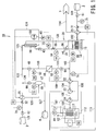
Fig. 1 is a constitution diagram of a hydrogen production system using high temperature steam electrolysis according to a first embodiment; -
Figs. 2 are views illustrating a change of an output of each control parameter with a change of a power supply output; -
Fig. 3 is a constitution diagram of a hydrogen production system using high temperature steam electrolysis according to a second embodiment; and -
Fig. 4 is a constitution diagram of a hydrogen production system using high temperature steam electrolysis according to a third embodiment. - This embodiment will be described below by referring to the attached drawings.
- As illustrated in
Fig. 1 , ahydrogen production system 10 by using high temperature steam electrolysis according to the first embodiment (hereinafter abbreviated as hydrogen production system 10) includes a plurality ofelectrolysis cells 11 provided inside areaction vessel 12 and performing high temperature steam electrolysis by receiving an input of high temperature steam generated in asteam generator 14, awater separator 18 for receiving an input of a mixture of the steam and hydrogen generated by the high temperature steam electrolysis outputted from theelectrolysis cell 11 and separating it to the steam and the hydrogen, ahydrogenation reactor 16 for receiving an input of a mixture of a supplied hydrogen storage material and the separated hydrogen and hydrogenating the hydrogen storage material, aheat medium loop 36 for transmitting heat energy generated when the hydrogen storage material is hydrogenated to water to be supplied into thesteam generator 14 through a circulating heat medium, a gas/liquid separator 17 for receiving an input of a mixture of the hydrogen storage material after hydrogenation and the hydrogen and separating it to the hydrogen storage material after hydrogenation and the hydrogen outputted from thehydrogenation reactor 16, a hydrogen storage material tank 4 for storing the separated hydrogen storage material after the hydrogenation, aselection unit 50 for selecting theelectrolysis cell 11 to which the electric power is supplied in accordance with fluctuation of electric power supplied to theelectrolysis cell 11, a firstheat control unit 51 for holding a temperature of theelectrolysis cell 11 at a predetermined temperature by using aheater 13 provided inside thereaction vessel 12, a first flowrate control unit 41 for adjusting a flow rate of the water to be supplied to thesteam generator 14 and holding a flow rate of the high temperature steam to be inputted into theelectrolysis cell 11 constant, and a second flowrate control unit 42 for adjusting a flow rate of the hydrogen storage material to be supplied in accordance with fluctuation of the electric power. - A
water tank 2 storesraw material water 101 to be decomposed to hydrogen and oxygen by high temperature steam electrolysis. Theraw material water 101 is suctioned by apump 61 and supplied to thesteam generator 14 through aheat exchanger 21. - The
raw material water 101 supplied to thesteam generator 14 is heated, converted to steam and outputted. A temperature ofsteam 103 outputted from thesteam generator 14 is raised to a set temperature required for high temperature steam electrolysis throughheat exchangers steam 106 is supplied to theelectrolysis cell 11 provided inside thereaction vessel 12. - The
electrolysis cells 11 are arranged around a solid oxide electrolyte (not shown) and a hydrogen electrode and an oxygen electrode are formed on both sides thereof. InFig. 1 , theelectrolysis cells 11 are constituted in four, but the number is not limited to this constitution, and theelectrolysis cells 11 also include an electrolysis cell stack formed having a stack shape by stacking the cells. - Each of the
electrolysis cells 11 is connected to arenewable power supply 1 and to which an electrolytic voltage is supplied. Therenewable power supply 1 indicates a power source using renewable energy such as wind power, hydro power, solar power and the like. - The
electrolysis cell 11 receives supply of electric power from therenewable power supply 1 and decomposes/generates suppliedsteam 106 into hydrogen and oxygen. Amixture 107 of steam and hydrogen is outputted from the hydrogen electrode into which the steam has been introduced, whileoxygen 112 is outputted from the oxygen electrode. - The
selection unit 50 monitors supplied power of therenewable power supply 1 and selects theelectrolysis cell 11 to be connected to therenewable power supply 1 in accordance with fluctuation of the supplied power. - Specifically, a number of connections of the
electrolysis cells 11 is determined so as to be proportional to the supplied power of therenewable power supply 1, and theelectrolysis cells 11 corresponding to the number of connections are connected to therenewable power supply 1. Theselection unit 50 sets theelectrolysis cells 11 to be connected to therenewable power supply 1 corresponding to the number of connection of theelectrolysis cells 11 in advance. As a result, an appropriate number ofelectrolysis cells 11 corresponding to the supplied power from therenewable power supply 1 are operated. - The
heater 13 is provided inside thereaction vessel 12 and heats theelectrolysis cell 11. - In the first
heat control unit 51, a temperature of theelectrolysis cell 11 is inputted from athermometer 81 and is monitored. The firstheat control unit 51 makes temperature control by using theheater 13 so that a temperature of theelectrolysis cell 11 becomes a predetermined temperature (temperature at which theelectrolysis cell 11 exerts its performances). - If the supplied power of the
renewable power supply 1 is reduced, theelectrolysis cell 11 to be connected to therenewable power supply 1 is selected by theselection unit 50, andoperating electrolysis cells 11 are reduced. In this case, since a heat generation amount generated by electrolysis reaction is reduced, the temperature of theelectrolysis cell 11 lowers. - By holding the temperature of the
electrolysis cell 11 at a predetermined temperature by using a heat input from theheater 13 through an operation of the firstheat control unit 51, even if the supplied power of therenewable power supply 1 is reduced, theelectrolysis cell 11 can be operated stably. - The first
heat control unit 51 may be constituted such that it monitors fluctuation of the electric power in therenewable power supply 1, calculates a heat amount required in accordance with the fluctuation of the electric power and holds the temperature of theelectrolysis cell 11 at a predetermined temperature by theheater 13 on the basis of this calculated heat amount. - In the first flow
rate control unit 41, a flow rate of steam on an output side of thesteam generator 14 is inputted from aflowmeter 74 and is monitored. Then, it adjusts a supply amount of water supplied from thewater tank 2 to thesteam generator 14 by using aflow control valve 31 and holds a flow rate of steam on the output side of thesteam generator 14 constant. - Since the
electrolysis cell 11 is operating in a high temperature state, constant supply of a steam amount is preferable from a viewpoint of stable operation. If the supplied power of therenewable power supply 1 is fluctuated, the steam amount used for electrolysis reaction in theelectrolysis cell 11 is also fluctuated in accordance with that. If the supplied steam amount is fluctuated in accordance with the fluctuation of the steam amount in use, there is a concern that theelectrolysis cell 11 cannot be operated stably. - Even if the supplied power of the
renewable power supply 1 is fluctuated, theelectrolysis cell 11 can be operated stably by holding the steam amount to be inputted into theelectrolysis cell 11 constant by an operation of the first flowrate control unit 41. - The
mixture 107 of steam and hydrogen outputted from the hydrogen electrode of theelectrolysis cell 11 performs heat exchange with steam supplied to theelectrolysis cell 11 in theheat exchangers mixture 109 of steam and hydrogen is inputted into thewater separator 18. On the other hand,oxygen 113 outputted from the oxygen electrode of theelectrolysis cell 11 performs heat exchange with theraw material water 101 in theheat exchanger 21 and is discharged from anoxygen outlet 5. - The
water separator 18 separates the inputtedmixture 109 of steam and hydrogen into steam and hydrogen. A temperature of themixture 109 of hydrogen and steam after being outputted from theheat exchanger 22 is approximately 150°C. Under this temperature condition, as a specific constitution of thewater separator 18, a separator using a pressure swing adsorption (PSA) method in which adsorption and desorption of moisture are repeated alternately in an adsorption tower filled with a molecular sieve can be considered. - Moreover, by removing moisture by applying a palladium film or a silica film to the
water separator 18, thewater separator 18 can be installed close to the output side of theelectrolysis cell 11 at a position where the mixture of hydrogen and steam is at a higher temperature (close to an output of theheat exchanger 24, for example). - Then, the
water separator 18 merges steam separated from thewater separator 18 to a position where the temperature is closest on a supply line of steam inputted into theelectrolysis cell 11. As a result, the steam can be merged with steam inputted into theelectrolysis cell 11 efficiently without lowering a temperature of separated steam. -
Steam 111 separated from thewater separator 18 is merged withsteam 103 outputted from thesteam generator 14 by suctioning of acompressor 64. - In a
control unit 53, an outlet pressure (steam output side) of thewater separator 18 is inputted from apressure meter 93 and is monitored. Then, the control unit adjusts thecompressor 64 so that this outlet pressure is held at a set pressure value. - On the other hand,
hydrogen 110 separated by thewater separator 18 is merged with a supply line through which a hydrogen storage material (toluene) is supplied to thehydrogenation reactor 16 by suctioning of thecompressor 65. - In a
control unit 54, an outlet pressure (hydrogen output side) of thewater separator 18 is inputted from apressure meter 92 and is monitored. Then, the control unit adjusts thecompressor 65 so that this outlet pressure is held at a set pressure value. - By using the
compressors water separator 18. - A hydrogen storage material tank 3 stores a hydrogen storage material for hydrogenation. Here, use of toluene as the hydrogen storage material will be described. As the hydrogen storage material, unsaturated hydrocarbon such as benzene, naphthalene and the like can be also applied.
-
Toluene 121 stored in the hydrogen storage material tank 3 is suctioned by apump 62 and merged and mixed with hydrogen separated in thewater separator 18. Then, amixture 123 of toluene and hydrogen is inputted into thehydrogenation reactor 16. - The
hydrogenation reactor 16 is filled with a catalyst suitable for hydrogenation reaction. In thehydrogenation reactor 16, hydrogenation reaction is conducted by inputted toluene and hydrogen, hydrogen is added to toluene, and methyl cyclohexane (MCH) is generated. Then, amixture 124 of MCH and hydrogen is outputted from thehydrogenation reactor 16. Then, themixture 124 of MCH and hydrogen is heat-exchanged with thetoluene 121 in theheat exchanger 25 and inputted into the gas/liquid separator 17. - In the second flow
rate control unit 42, a concentration of hydrogen on the output side of thehydrogenation reactor 16 is inputted from ahydrogen concentration meter 100 and is monitored. Then, the second flow rate control unit adjusts a flow rate of toluene by using aflow control valve 32 and holds a hydrogen concentration on the output side of thehydrogenation reactor 16 constant. - If the supplied power of the
renewable power supply 1 lowers, a hydrogen amount manufactured in theelectrolysis cell 11 lowers. If a flow rate of toluene is constant, a ratio of hydrogen to toluene is changed, whereby a reaction rate and a selection rate are affected, and there is a concern that reaction heat might be fluctuated. - If a supply amount of toluene is constant while the hydrogen amount lowers, there is a concern that unreacted toluene is generated in the
hydrogenation reactor 16. Since separation of MCH and toluene from each other becomes difficult, an output in thehydrogenation reactor 16 needs to be a mixture of MCH and unreacted hydrogen. - By adjusting a supply flow-rate of toluene so that the concentration of hydrogen outputted from the
hydrogenation reactor 16 is held constant by an operation of the second flowrate control unit 42, a ratio of hydrogen to toluene is maintained, and hydrogenation reaction can be conducted stably. Moreover, generation of unreacted toluene can be suppressed. - It is needless to say that a point that hydrogen is monitored at an outlet of the
hydrogenation reactor 16 so that toluene should not remain can be also applied to supply of constant power. - In the
hydrogenation reactor 16, heat energy is generated by hydrogenation reaction of toluene. - The
heat medium loop 36 forms a loop through which aheat medium 131 circulates via thehydrogenation reactor 16 and thesteam generator 14. The heat medium is circulated by acompressor 63. The circulating heat medium transmits heat energy generated by hydrogenation reaction of toluene to water stored in thesteam generator 14 and converts it to steam. - A cooler 26 is provided on a heat medium input side of the
hydrogenation reactor 16 on theheat medium loop 36 and cools the circulating heat medium by a refrigerant. - In a refrigerant flow
rate control unit 44, a temperature of the heat medium circulating through theheat medium loop 36 is inputted from athermometer 84 and is monitored. Then, when this temperature is fluctuated, a flow rate of the refrigerant poured into the cooler 26 is adjusted by using aflow control valve 34, and a temperature of the heat medium is held constant. - By holding the temperature of the heat medium constant by the refrigerant flow
rate control unit 44, toluene and hydrogen reacted in thehydrogenation reactor 16 can be reacted under a same temperatures condition. - In a heat medium flow
rate control unit 43, a temperature on the output side of thehydrogenation reactor 16 is inputted from athermometer 83 and is monitored. Then, when this temperature drops, a flow rate of the heat medium is adjusted (reduced) by using aflowmeter 73 and aflow control valve 33 provided on theheat medium loop 36 so as to hold the temperature on the output side of thehydrogenation reactor 16 at a set temperature or more. - If a hydrogen flow rate inputted into the
hydrogenation reactor 16 lowers, heat energy by the hydrogenation reaction lowers. At this time, if the flow rate of the heat medium is made constant and a moving amount of heat energy to the heat medium is constant, a temperature on the output side of thehydrogenation reactor 16 lowers. - By reducing the flow rate of the heat medium and by reducing the moving amount of heat energy to the heat medium by an operation of the heat medium flow
rate control unit 43, a temperature drop on the output side of thehydrogenation reactor 16 is suppressed. Thus, heat exchange between themixture 124 of MCH and hydrogen and thetoluene 121 supplied from the hydrogen storage material tank 3 can be performed appropriately. As a result, an input of thetoluene 121 in a liquid state into thehydrogenation reactor 16 can be prevented. - In an auxiliary
heater control unit 52, a temperature of thesteam 103 outputted from thesteam generator 14 is inputted from athermometer 82 and is monitored. Then, temperature control is executed by using anauxiliary heater 15 provided in thesteam generator 14 so that a temperature of steam outputted from thesteam generator 14 becomes a set value or more. - Since a heat input into the
steam generator 14 is assisted by the auxiliaryheater control unit 52, a temperature of steam outputted from thesteam generator 14 is held at a set value or more. - The
mixture 124 of MCH and hydrogen outputted from thehydrogenation reactor 16 is heat-exchanged with thetoluene 121 in theheat exchanger 25 and is inputted into the gas/liquid separator 17. - In the gas/
liquid separator 17, themixture 125 of MCH and hydrogen is inputted, and MCH and hydrogen are separated from each other.Hydrogen 126 separated by the gas/liquid separator 17 is merged with toluene supplied from the hydrogen storage material tank 3 by suctioning of acompressor 66 and becomes amixture 122 of toluene and hydrogen. - In a
control unit 55, an outlet pressure (hydrogen output side) of the gas/liquid separator 17 is inputted from apressure meter 91 and is monitored. Thecompressor 66 is adjusted so that the outlet pressure is held at a set value. By using thecompressor 66, hydrogen can be supplied stably to a system higher than a pressure of the gas/liquid separator 17. - On the other hand, the separated MCH is stored in the hydrogen storage material tank 4.
- Here, an operation of each control parameter if the power supplied from the
renewable power supply 1 is fluctuated will be described specifically. -
Figs. 2 are diagrams for explaining an operation of each control parameter if the power supplied from therenewable power supply 1 is reduced (seeFig. 1 as appropriate).Fig. 2A illustrates a state in which the power supplied from therenewable power supply 1 is sequentially reduced. - First, the
selection unit 50 monitors the supplied power of therenewable power supply 1, selects theelectrolysis cell 11 connected to therenewable power supply 1 in accordance with the reduction of the supplied power and reduces the connection number. - Since the temperature of the
electrolysis cell 11 drops with the reduction of the operatingelectrolysis cells 11, the firstheat control unit 51 increases a heat input from the heater 13 (Fig. 2B ) and holds theelectrolysis cell 11 at a predetermined temperature. - If the supplied power from the
renewable power supply 1 is reduced, a steam amount used for electrolysis reaction in theelectrolysis cell 11 lowers. - The first flow
rate control unit 41 reduces a supply amount of water supplied from thewater tank 2 to thesteam generator 14 by using aflowmeter 71 and the flow control valve 31 (Fig. 2C ) and holds a flow rate of the steam on the output side of thesteam generator 14 constant. - If the supplied power from the
renewable power supply 1 is reduced, a steam reaction amount in high temperature steam electrolysis lowers and thus, a hydrogen flow rate supplied to thehydrogenation reactor 16 is reduced. - The second flow
rate control unit 42 holds the concentration of hydrogen outputted from thehydrogenation reactor 16 constant by reducing a supply flow rate of toluene (Fig. 2D ). - If the supplied power from the
renewable power supply 1 is reduced, since flow rates of hydrogen and toluene to be supplied to thehydrogenation reactor 16 are reduced, generated reaction heat is reduced. - The heat medium flow
rate control unit 43 reduces the moving amount of heat energy to the heat medium by reducing the flow rate of the heat medium (Fig. 2E ) and suppresses temperature drop on the output side of thehydrogenation reactor 16. - If the supplied power from the
renewable power supply 1 is reduced, the flow rates of hydrogen and toluene supplied to thehydrogenation reactor 16 are reduced, and generated reaction heat is reduced. - The refrigerant flow
rate control unit 44 causes the toluene and hydrogen reacted in thehydrogenation reactor 16 to be reacted under the same temperature condition by reducing the flow rate of the refrigerant (Fig. 2F ). - If the supplied power from the
renewable power supply 1 is reduced, a supply water amount to thesteam generator 14 is reduced. - The auxiliary
heater control unit 52 holds a temperature of steam outputted from thesteam generator 14 at a set temperature or more by reducing a heat input amount into the steam generator 14 (Fig. 2G ). - As described above, by selecting the
electrolysis cell 11 to be operated in accordance with power fluctuation of therenewable power supply 1 and by adjusting the temperature of theelectrolysis cell 11 and flow rates of high temperature steam and the hydrogen storage material appropriately, stable operation control can be realized even if the renewable power supply in which power fluctuation occurs is used. - Moreover, by separating hydrogen and excessive steam outputted from the
electrolysis cell 11 from each other, by returning the steam to a supply side of theelectrolysis cell 11, and by providing the hydrogen to hydrogenation reaction with toluene, high hydrogen manufacture efficiency can be realized. - In the aforementioned embodiment, the
renewable power supply 1 is described as a power supply, but it is needless to say that a normal constant-voltage power supply can be also used. -
Fig. 3 illustrates a constitution diagram of thehydrogen production system 10 according to a second embodiment. Same reference numerals are given to constitutions and portions corresponding to those in the first embodiment and duplicated explanation will be omitted. - A difference in the second embodiment from the
hydrogen production system 10 according to the first embodiment is that ahydrogen storage tank 6 for storing hydrogen separated in the gas/liquid separator 17 and a hydrogen flowrate control unit 58 for holding a space speed in thehydrogenation reactor 16 constant by adjusting an inflow amount to allow hydrogen stored in thehydrogen storage tank 6 to flow into thehydrogenation reactor 16 are further provided. - The
hydrogen storage tank 6 stores thehydrogen 126 separated by the gas/liquid separator 17. The stored hydrogen is suctioned by acompressor 67 and merged with a supply line through which toluene is supplied from the hydrogen storage material tank 3 to thehydrogenation reactor 16. Then, it is mixed with toluene and is made to flow into thehydrogenation reactor 16. - In the hydrogen flow
rate control unit 58, a flow rate of steam on an output side of thesteam generator 14 from theflowmeter 71 and a flow rate of toluene supplied from aflowmeter 72 are inputted and monitored. - Then, a hydrogen amount to be manufactured in the
electrolysis cell 11 is estimated from the flow rate of the steam and the space speed in thehydrogenation reactor 16 is acquired from this hydrogen amount and the flow rate of toluene. The space speed means a speed obtained by dividing a total of supply flow rate in thehydrogenation reactor 16 by a filled volume of a catalyst in thehydrogenation reactor 16. - Then, the hydrogen flow
rate control unit 58 adjusts a supply amount to be made to flow from thehydrogen storage tank 6 into thehydrogenation reactor 16 by using aflowmeter 75 and a flow control valve 35 (or the compressor 67) and holds the space speed in thehydrogenation reactor 16 constant. - If the supplied power of the
renewable power supply 1 is reduced, a manufactured amount of hydrogen in theelectrolysis cell 11 is reduced, and a toluene supply flow rate to thehydrogenation reactor 16 is also reduced. As a result, the space speed in thehydrogenation reactor 16 is reduced and there is a concern that reaction efficiency of hydrogen and toluene in thehydrogenation reactor 16 is lowered. - By maintaining the space speed in the
hydrogenation reactor 16 constant by the hydrogen flowrate control unit 58 by supplying hydrogen from thehydrogen storage tank 6, drop of the reaction efficiency of the hydrogen and toluene in thehydrogenation reactor 16 can be suppressed. - In a hydrogen
heater control unit 60, an inlet temperature of thehydrogenation reactor 16 is inputted from athermometer 85 and is monitored. Then, temperature adjustment is executed so that a temperature of inflow hydrogen becomes a set value or more by using thehydrogen heater 20 provided along an inflow line for inflow into thehydrogenation reactor 16. - The hydrogen stored in the
hydrogen storage tank 6 is at a low temperature since it was obtained by heat exchange in theheat exchanger 25 but is made possible to flow into thehydrogenation reactor 16 after a temperature is raised by an operation of the hydrogenheater control unit 60. - Moreover, in
Fig. 3 , variations of control methods of the first flowrate control unit 41 and the second flowrate control unit 42 are illustrated, respectively. - The first flow
rate control unit 41 monitors fluctuation of electric power in therenewable power supply 1 and forecasts a steam amount to be consumed in high temperature steam electrolysis in accordance with the fluctuation of electric power. - The supply amount of water to be supplied from the
water tank 2 to thesteam generator 14 is adjusted by using theflowmeter 71 and theflow control valve 31 so that a flow rate of steam made to flow into theelectrolysis cell 11 is held constant on the basis of this forecast value. - The second flow
rate control unit 42 monitors fluctuation of electric power in therenewable power supply 1 and a water supply flow rate to thesteam generator 14 by using theflowmeter 71 and forecasts a steam amount to be consumed by high temperature steam electrolysis. - Hydrogen to be manufactured is calculated on the basis of this forecast steam amount, and a supply flow rate of toluene is adjusted by using the
flowmeter 72 and theflow control valve 32 so as to match this hydrogen flow rate. -
Fig. 4 illustrates a constitution diagram of thehydrogen production system 10 according to a third embodiment. Same reference numerals are given to constitutions and portions corresponding to those in the first embodiment and duplicated explanation will be omitted. - A difference in the third embodiment from the
hydrogen production system 10 according to the first embodiment is that thehydrogenation reactor 16 and thesteam generator 14 are integrated, and steam is generated in thehydrogenation reactor 16 to which water is supplied. - In the third embodiment, there is no supply of water to the
steam generator 14 once so as to convert the water to steam (seeFig. 1 ) but water is supplied to thehydrogenation reactor 16 and directly converted to steam by hydrogenation reaction heat. - In a steam
heater control unit 56, a temperature of thesteam 103 outputted from thehydrogenation reactor 16 is inputted from thethermometer 82 and is monitored. Then, temperature adjustment is executed so that a temperature of steam outputted from thehydrogenation reactor 16 becomes a set temperature or more by using asteam heater 19 provided along a supply line of steam. - As described above, by integrating the
hydrogenation reactor 16 and thesteam generator 14, the entire apparatus can be constituted compactly. - According to the hydrogen production system of each embodiment described above, by selecting the electrolysis cell to be operated in accordance with fluctuation of electric power and by adjusting a temperature of the electrolysis cell and flow rates of the high temperature steam and the hydrogen storage material appropriately, stable operation control can be realized even if the renewable power supply in which electric power fluctuation occurs is used.
- Some embodiments of the present invention are described but these embodiments are presented as examples and are not intended to limit a range of the invention. These new embodiments can be put into practice in other various forms and are capable of various types of omission, replacement, and change within a range not departing from a gist of the invention. These embodiments and their variations are included in the range and the gist of the invention and also included in the range of invention described in claims and their equivalents.
- 1 ...renewable power supply, 2 ...water tank, 3 ...hydrogen storage material tank (before hydrogen storage), 4 ...hydrogen storage material tank (after hydrogen storage), 5 ...oxygen outlet, 6 ... hydrogen storage tank, 10 ...hydrogen production system, 11 ...electrolysis cell, 12 ...reaction vessel, 13 ...heater, 14 ...steam generator, 15 ...auxiliary heater, 16 ...hydrogenating reactor, 17 ... gas / liquid separator, 18 ...water separator, 19 ...steam heater, 20 ...hydrogen heater, 21, 22, 23, 24, 25 ...heat exchanger, 26 ...cooler, 31, 32, 33, 34, 35 ...flow control valve, 36 ...heat medium loop, 41 ...first flow rate control unit, 42 ...second flow rate control unit, 43 ...heat medium flow-rate control unit, 44 ...refrigerant flow-rate control unit, 50... selection unit, 51...first temperature control unit, 52...auxiliary heater control unit, 53, 54, 55 ...control unit, 56...steam heater control unit, 58...hydrogen flow-rate control unit, 60...hydrogen heater control unit, 61, 62 ...pump, 63, 64, 65, 66, 67 ...compressor, 71, 72, 73, 74, 75 ...flowmeter, 81, 82, 83, 84, 85 ...thermometer, 91, 92, 93 ...pressure meter, 100 ...hydrogen concentration meter, 101, 102 ...water, 103, 104, 105, 106 ...steam, 107, 108, 109 ...mixture (hydrogen and steam), 110 ... hydrogen, 111 ... steam, 112, 113, 114 ... oxygen, 121 ... toluene, 122, 123, 114 ...mixture (toluene and hydrogen), 124, 125 ...mixture (MCH and hydrogen), 126 ...hydrogen, 127 ...MCH, 128 ...hydrogen, 131 ...heat medium
Claims (12)
- A hydrogen production system by using high temperature steam electrolysis, comprising:a plurality of electrolysis cells provided inside a reaction vessel and performing high temperature steam electrolysis by receiving an input of steam generated in a steam generator;a water separator for receiving an input of a mixture of steam and hydrogen generated by the high temperature steam electrolysis outputted from the electrolysis cell and separating the mixture to the steam and the hydrogen;a hydrogenation reactor for receiving an input of a mixture of a supplied hydrogen storage material and the separated hydrogen and hydrogenating the hydrogen storage material:a heat medium loop for transmitting heat energy generated when the hydrogen storage material is hydrogenated to water to be supplied into the steam generator through a circulating heat medium;a gas/liquid separator for receiving an input of a mixture of the hydrogen storage material after hydrogenation and the hydrogen and separating the mixture to the hydrogen storage material after hydrogenation and the hydrogen outputted from the hydrogenation reactor;a hydrogen storage material tank for storing the separated hydrogen storage material after the hydrogenation;a selection unit for selecting the electrolysis cell to which the electric power is supplied in accordance with fluctuation of electric power supplied to the electrolysis cell;a first heat control unit for holding a temperature of the electrolysis cell at a predetermined temperature by using a heater provided in the reaction vessel;a first flow rate control unit for adjusting a flow rate of the water to be supplied to the steam generator and holding a flow rate of the steam to be inputted into the electrolysis cell constant; anda second flow rate control unit for adjusting a flow rate of the hydrogen storage material to be supplied in accordance with fluctuation of the electric power.
- The hydrogen production system by using high temperature steam electrolysis according to claim 1, wherein
the second flow rate control unit adjusts the flow rate of the hydrogen storage material to be supplied and holds a concentration of the hydrogen outputted from the hydrogenation reactor at a predetermined concentration. - The hydrogen production system by using high temperature steam electrolysis according to claim 1, further comprising:an auxiliary heater control unit for adjusting a heating temperature of an auxiliary heater provided in the steam generator and making a temperature of the steam outputted from the steam generator be a set value or more.
- The hydrogen production system by using high temperature steam electrolysis according to claim 1, further comprising:a cooler provided on the heat medium loop and cooling the heat medium by a refrigerant; anda refrigerant flow rate control unit for adjusting a flow rate of the refrigerant flowing into the cooler and for holding a temperature of the circulating heat medium constant.
- The hydrogen production system by using high temperature steam electrolysis according to claim 1, further comprising:a heat medium flow rate control unit for adjusting a flow rate of the heat medium and holding a temperature on an output side of the hydrogenation reactor at a set temperature or more.
- The hydrogen production system by using high temperature steam electrolysis according to claim 1, further comprising:a hydrogen storage tank for storing the hydrogen separated in the gas/liquid separator; anda hydrogen flow rate control unit for adjusting an inflow amount to allow the hydrogen stored in the hydrogen storage tank to flow into the hydrogenation reactor and for holding a space speed flowing through the hydrogenation reactor constant.
- The hydrogen production system by using high temperature steam electrolysis according to claim 6, further comprising:a hydrogen heater control unit for adjusting a heating temperature of a hydrogen heater provided along an inflow line through which the hydrogen stored in the hydrogen storage tank is made to flow into the hydrogenation reactor and for making a temperature of the hydrogen to be made to flow into the hydrogenation reactor from the hydrogen storage tank be a set value or more.
- The hydrogen production system by using high temperature steam electrolysis according to claim 1, wherein
the hydrogenation reactor and the steam generator are integrated and the steam is generated in the hydrogenation reactor to which water was supplied. - The hydrogen production system by using high temperature steam electrolysis according to claim 1, wherein
the hydrogen storage material is unsaturated hydrocarbon. - The hydrogen production system by using high temperature steam electrolysis according to claim 1, wherein
the steam separated by the water separator is merged with the steam inputted into the electrolysis cell. - The hydrogen production system by using high temperature steam electrolysis according to claim 1, wherein
the steam separated by the water separator is merged at a position where a temperature is closest on a supply line of the steam to be inputted into the electrolysis cell. - A method for producing hydrogen by using high temperature steam electrolysis comprising steps of:inputting steam generated in a steam generator and performing high temperature steam electrolysis using a plurality of electrolysis cells provided inside a reaction vessel;inputting a mixture of the steam and hydrogen generated by the high temperature steam electrolysis outputted from the electrolysis cell and separating the mixture to the steam and the hydrogen;inputting a mixture of a supplied hydrogen storage material and the separated hydrogen and hydrogenating the hydrogen storage material in a hydrogenation reactor:transmitting heat energy generated when the hydrogen storage material is hydrogenated to water to be supplied into the steam generator through a circulating heat medium;inputting a mixture of the hydrogen storage material after hydrogenation and the hydrogen and separating the mixture to the hydrogen storage material after hydrogenation and the hydrogen outputted from the hydrogenation reactor;storing the separated hydrogen storage material after the hydrogenation;selecting the electrolysis cell to which the electric power is supplied in accordance with fluctuation of electric power supplied to the electrolysis cell;holding a temperature of the electrolysis cell at a predetermined temperature by using a heater provided in the reaction vessel;adjusting a flow rate of the water to be supplied to the steam generator and holding a flow rate of the steam to be inputted into the electrolysis cell constant; andadjusting a flow rate of the hydrogen storage material to be supplied in accordance with fluctuation of the electric power.
Applications Claiming Priority (2)
| Application Number | Priority Date | Filing Date | Title |
|---|---|---|---|
| JP2014143527A JP6346013B2 (en) | 2014-07-11 | 2014-07-11 | Hydrogen production apparatus and method using high temperature steam electrolysis |
| PCT/JP2015/069922 WO2016006692A1 (en) | 2014-07-11 | 2015-07-10 | Apparatus and method for hydrogen production using high-temperature water vapor electrolysis |
Publications (3)
| Publication Number | Publication Date |
|---|---|
| EP3168330A1 true EP3168330A1 (en) | 2017-05-17 |
| EP3168330A4 EP3168330A4 (en) | 2018-01-24 |
| EP3168330B1 EP3168330B1 (en) | 2019-07-03 |
Family
ID=55064320
Family Applications (1)
| Application Number | Title | Priority Date | Filing Date |
|---|---|---|---|
| EP15818541.3A Not-in-force EP3168330B1 (en) | 2014-07-11 | 2015-07-10 | Apparatus and method for hydrogen production using high-temperature water vapor electrolysis |
Country Status (5)
| Country | Link |
|---|---|
| EP (1) | EP3168330B1 (en) |
| JP (1) | JP6346013B2 (en) |
| AR (1) | AR104467A1 (en) |
| DK (1) | DK3168330T3 (en) |
| WO (1) | WO2016006692A1 (en) |
Cited By (11)
| Publication number | Priority date | Publication date | Assignee | Title |
|---|---|---|---|---|
| CN114196968A (en) * | 2021-12-08 | 2022-03-18 | 国能大渡河流域水电开发有限公司 | Solid oxide water electrolysis hydrogen production device and operation control method thereof |
| WO2022090150A1 (en) * | 2020-10-30 | 2022-05-05 | Commissariat A L'energie Atomique Et Aux Energies Alternatives | High temperature electrolyser system optimised by increasing the pressure at the electrolyser output |
| WO2022214509A1 (en) * | 2021-04-09 | 2022-10-13 | Robert Bosch Gmbh | Solid oxide electrolysis cell device, method for operating a solid oxide electrolysis cell device, and solid oxide electrolysis cell system |
| EP4159894A1 (en) * | 2021-09-30 | 2023-04-05 | SolydEra SA | Steam electrolyser system for the production of hydrogen and corresponding method |
| WO2023144775A1 (en) * | 2022-01-27 | 2023-08-03 | Bloom Energy Corporation | Internal steam delivery system |
| WO2023227711A1 (en) * | 2022-05-25 | 2023-11-30 | Hydrogenious Lohc Technologies Gmbh | Process and reactor assembly for the hydrogenation of a carrier medium for hydrogen |
| WO2023227710A1 (en) * | 2022-05-25 | 2023-11-30 | Hydrogenious Lohc Technologies Gmbh | Hydrogenation process and dehydrogenation process for a carrier medium for hydrogen and system for carrying out processes of this kind |
| DE102023208644A1 (en) | 2023-09-07 | 2025-03-13 | Robert Bosch Gesellschaft mit beschränkter Haftung | Method for operating an electrolysis plant, control unit |
| US12291791B2 (en) | 2022-01-07 | 2025-05-06 | Bloom Energy Corporation | Steam use and safety systems |
| EP4240888A4 (en) * | 2022-01-27 | 2025-11-12 | Bloom Energy Corp | INTERNAL VAPOR RELEASE SYSTEM |
| RU2855548C2 (en) * | 2021-09-30 | 2026-02-02 | Солидера Са | Steam electrolysis system for hydrogen production and corresponding method |
Families Citing this family (15)
| Publication number | Priority date | Publication date | Assignee | Title |
|---|---|---|---|---|
| WO2017149606A1 (en) * | 2016-02-29 | 2017-09-08 | 株式会社 東芝 | Hydrogen production system, and hydrogen production method |
| JP6919506B2 (en) * | 2017-11-02 | 2021-08-18 | 富士通株式会社 | Electrolysis system, electrolysis control device and control method of electrolysis system |
| JP7110042B2 (en) * | 2018-09-13 | 2022-08-01 | 東芝エネルギーシステムズ株式会社 | Hydrogen production device and hydrogen production method |
| DE102019125641A1 (en) * | 2019-09-24 | 2021-03-25 | Dr. Ing. H.C. F. Porsche Aktiengesellschaft | Method and device for storing electrical energy |
| DE102020104964B4 (en) | 2020-02-26 | 2022-06-30 | Mol Katalysatortechnik Gmbh | Device and method for the electrolytic generation of hydrogen from water at room temperature and normal pressure and use of a mineral-metal foil |
| EP3901329A1 (en) | 2020-04-23 | 2021-10-27 | sunfire GmbH | Solid oxide cell system operating method |
| DE102020210478A1 (en) | 2020-08-18 | 2022-02-24 | Thyssenkrupp Ag | Process for hydrogen synthesis using heat from a heat network using a high-temperature electrolysis system |
| FR3126129B1 (en) * | 2021-08-10 | 2025-04-18 | Commissariat Energie Atomique | High-temperature electrolyzer system optimized by an intermediate circuit recovery module |
| KR20230110211A (en) * | 2022-01-14 | 2023-07-21 | 블룸 에너지 코퍼레이션 | Steam recycle control |
| JP7848574B2 (en) * | 2022-04-27 | 2026-04-21 | 株式会社デンソー | Steam utilization system |
| CN115449819B (en) * | 2022-10-26 | 2023-07-25 | 江苏金卫星能源科技有限公司 | Alkaline water electrolysis hydrogen production device with wide input power |
| JP7611952B2 (en) * | 2023-02-17 | 2025-01-10 | 三菱重工業株式会社 | Electrolytic cell system and method for operating the electrolytic cell system |
| WO2025105416A1 (en) * | 2023-11-16 | 2025-05-22 | 日本特殊陶業株式会社 | Solid oxide electrolyzer cell and use of same |
| WO2025225466A1 (en) * | 2024-04-25 | 2025-10-30 | 株式会社堀場製作所 | Evaluation system, program for evaluation system, and evaluation method |
| CN118223074B (en) * | 2024-05-24 | 2024-08-13 | 山东国创燃料电池技术创新中心有限公司 | Method and device for controlling temperature of electrolytic tank of electrolytic water hydrogen production system |
Family Cites Families (9)
| Publication number | Priority date | Publication date | Assignee | Title |
|---|---|---|---|---|
| JP4406866B2 (en) * | 2003-10-27 | 2010-02-03 | 株式会社Ihi | Hydrogen production facility |
| US7510640B2 (en) * | 2004-02-18 | 2009-03-31 | General Motors Corporation | Method and apparatus for hydrogen generation |
| JP5288840B2 (en) * | 2008-03-17 | 2013-09-11 | Jx日鉱日石エネルギー株式会社 | Hydrogen production system |
| JP2010280975A (en) * | 2009-06-05 | 2010-12-16 | Mitsubishi Heavy Ind Ltd | Water electrolysis system and hydrogen utilization system |
| US9028781B2 (en) * | 2010-12-03 | 2015-05-12 | Hitachi, Ltd. | Renewable energy storage system |
| JPWO2012147157A1 (en) * | 2011-04-26 | 2014-07-28 | 株式会社日立製作所 | Energy storage and supply equipment |
| GB201202791D0 (en) * | 2012-02-20 | 2012-04-04 | Simpson Robert | Methods and system for energy conversion and generation |
| JP5711687B2 (en) * | 2012-03-23 | 2015-05-07 | 東京瓦斯株式会社 | Electrochemical device and power storage system |
| JP6437191B2 (en) * | 2013-12-09 | 2018-12-12 | 千代田化工建設株式会社 | Hydrogen production system, hydrogen storage / transport system equipped with the same, and hydrogen production method |
-
2014
- 2014-07-11 JP JP2014143527A patent/JP6346013B2/en not_active Expired - Fee Related
-
2015
- 2015-07-10 DK DK15818541.3T patent/DK3168330T3/en active
- 2015-07-10 EP EP15818541.3A patent/EP3168330B1/en not_active Not-in-force
- 2015-07-10 AR ARP150102214A patent/AR104467A1/en active IP Right Grant
- 2015-07-10 WO PCT/JP2015/069922 patent/WO2016006692A1/en not_active Ceased
Cited By (18)
| Publication number | Priority date | Publication date | Assignee | Title |
|---|---|---|---|---|
| US12618161B2 (en) | 2020-10-30 | 2026-05-05 | Commissariat A L'energie Atomique Et Aux Energies Alternatives | High temperature electrolyser system optimized by increasing the pressure at the electrolyser output |
| WO2022090150A1 (en) * | 2020-10-30 | 2022-05-05 | Commissariat A L'energie Atomique Et Aux Energies Alternatives | High temperature electrolyser system optimised by increasing the pressure at the electrolyser output |
| FR3115797A1 (en) * | 2020-10-30 | 2022-05-06 | Commissariat A L'energie Atomique Et Aux Energies Alternatives | High temperature electrolyser system optimized by increasing the pressure at the electrolyser outlet |
| WO2022214509A1 (en) * | 2021-04-09 | 2022-10-13 | Robert Bosch Gmbh | Solid oxide electrolysis cell device, method for operating a solid oxide electrolysis cell device, and solid oxide electrolysis cell system |
| MA64898B1 (en) * | 2021-09-30 | 2025-02-28 | Solydera Sa | Steam electrolyser system for the production of hydrogen and corresponding method |
| EP4159894A1 (en) * | 2021-09-30 | 2023-04-05 | SolydEra SA | Steam electrolyser system for the production of hydrogen and corresponding method |
| RU2855548C2 (en) * | 2021-09-30 | 2026-02-02 | Солидера Са | Steam electrolysis system for hydrogen production and corresponding method |
| MA64898A1 (en) * | 2021-09-30 | 2024-07-31 | Solydera Sa | Steam electrolyser system for the production of hydrogen and corresponding method |
| WO2023052135A1 (en) * | 2021-09-30 | 2023-04-06 | Solydera Sa | Steam electrolyser system for the production of hydrogen and corresponding method |
| CN114196968A (en) * | 2021-12-08 | 2022-03-18 | 国能大渡河流域水电开发有限公司 | Solid oxide water electrolysis hydrogen production device and operation control method thereof |
| CN114196968B (en) * | 2021-12-08 | 2023-11-24 | 国能大渡河流域水电开发有限公司 | Solid oxide water electrolysis hydrogen production device and operation control method thereof |
| US12291791B2 (en) | 2022-01-07 | 2025-05-06 | Bloom Energy Corporation | Steam use and safety systems |
| US12091764B2 (en) | 2022-01-27 | 2024-09-17 | Bloom Energy Corporation | Internal steam delivery system |
| EP4240888A4 (en) * | 2022-01-27 | 2025-11-12 | Bloom Energy Corp | INTERNAL VAPOR RELEASE SYSTEM |
| WO2023144775A1 (en) * | 2022-01-27 | 2023-08-03 | Bloom Energy Corporation | Internal steam delivery system |
| WO2023227710A1 (en) * | 2022-05-25 | 2023-11-30 | Hydrogenious Lohc Technologies Gmbh | Hydrogenation process and dehydrogenation process for a carrier medium for hydrogen and system for carrying out processes of this kind |
| WO2023227711A1 (en) * | 2022-05-25 | 2023-11-30 | Hydrogenious Lohc Technologies Gmbh | Process and reactor assembly for the hydrogenation of a carrier medium for hydrogen |
| DE102023208644A1 (en) | 2023-09-07 | 2025-03-13 | Robert Bosch Gesellschaft mit beschränkter Haftung | Method for operating an electrolysis plant, control unit |
Also Published As
| Publication number | Publication date |
|---|---|
| JP2016020517A (en) | 2016-02-04 |
| AR104467A1 (en) | 2017-07-26 |
| EP3168330B1 (en) | 2019-07-03 |
| EP3168330A4 (en) | 2018-01-24 |
| WO2016006692A1 (en) | 2016-01-14 |
| JP6346013B2 (en) | 2018-06-20 |
| DK3168330T3 (en) | 2019-10-07 |
Similar Documents
| Publication | Publication Date | Title |
|---|---|---|
| EP3168330B1 (en) | Apparatus and method for hydrogen production using high-temperature water vapor electrolysis | |
| CN114574877B (en) | Water electrolysis hydrogen production system with waste heat utilization | |
| CA3167525C (en) | Method and apparatus for managing industrial gas production | |
| CA3117925C (en) | Method of producing hydrogen | |
| CN117153280B (en) | Simulation model building method, simulation method and simulation system of alkaline electrolysis hydrogen production system | |
| JP5908457B2 (en) | Equipment for electrical energy storage and restoration | |
| US7360563B2 (en) | System and method for refueling a hydrogen vessel | |
| CN105449250B (en) | A kind of multikilowatt reversible solid oxide fuel cell electrolytic cell test system | |
| JP5653452B2 (en) | Natural energy storage system | |
| US11978935B2 (en) | Apparatus and system for generating nitrogen gas through dehumidifying and filtering fuel cell exhaust gas | |
| JP2013049600A (en) | Regenerable energy storage system | |
| JP5976950B1 (en) | Power supply system and control method thereof | |
| JP7765109B2 (en) | Nitrogen gas generator and system for filtering high-pressure fuel cell exhaust gas | |
| CN115418656B (en) | A skid-mounted hydrogen production, solid-state hydrogen storage and hydrogen fuel cell integrated system and operation method | |
| DK2803755T3 (en) | A method for operating a high-pressure electrolysis installation, the high pressure electrolysers and hydrogen-charging station with a high pressure electrolysers | |
| EP4332694A1 (en) | A method and system for controlling production and storage of industrial gases | |
| JP2020008039A (en) | Hydrogen shipping equipment and hydrogen shipping system | |
| JP2019077924A (en) | Hydrogen production, storage, and consumption system | |
| JP2007205667A (en) | Liquefied hydrogen production device | |
| EP2485310B1 (en) | Fuel cell device | |
| JP2017027936A (en) | Power supply system and control method thereof | |
| WO2025041428A1 (en) | Water electrolysis system and water electrolysis system control device | |
| US20250347016A1 (en) | Method of operating an electrolyzer | |
| JP2026060236A (en) | Co-electrolytic methanation device | |
| US20230175706A1 (en) | Integrated systems for generating thermal energy and hydrogen |
Legal Events
| Date | Code | Title | Description |
|---|---|---|---|
| STAA | Information on the status of an ep patent application or granted ep patent |
Free format text: STATUS: THE INTERNATIONAL PUBLICATION HAS BEEN MADE |
|
| PUAI | Public reference made under article 153(3) epc to a published international application that has entered the european phase |
Free format text: ORIGINAL CODE: 0009012 |
|
| STAA | Information on the status of an ep patent application or granted ep patent |
Free format text: STATUS: REQUEST FOR EXAMINATION WAS MADE |
|
| 17P | Request for examination filed |
Effective date: 20161212 |
|
| AK | Designated contracting states |
Kind code of ref document: A1 Designated state(s): AL AT BE BG CH CY CZ DE DK EE ES FI FR GB GR HR HU IE IS IT LI LT LU LV MC MK MT NL NO PL PT RO RS SE SI SK SM TR |
|
| AX | Request for extension of the european patent |
Extension state: BA ME |
|
| RIN1 | Information on inventor provided before grant (corrected) |
Inventor name: OOMURA, HISAO Inventor name: WATANABE, HISAO Inventor name: YAMADA, MASAHIKO Inventor name: FUJIWARA, SEIJI Inventor name: KASAI, SHIGEO Inventor name: MAKINO, SHINICHI Inventor name: YAMADA, KAZUYA |
|
| DAV | Request for validation of the european patent (deleted) | ||
| DAX | Request for extension of the european patent (deleted) | ||
| A4 | Supplementary search report drawn up and despatched |
Effective date: 20180104 |
|
| RIC1 | Information provided on ipc code assigned before grant |
Ipc: C25B 1/04 20060101ALI20171219BHEP Ipc: C25B 15/08 20060101ALI20171219BHEP Ipc: C25B 15/02 20060101AFI20171219BHEP Ipc: C25B 9/00 20060101ALI20171219BHEP Ipc: C25B 9/18 20060101ALI20171219BHEP Ipc: C01B 3/00 20060101ALN20171219BHEP |
|
| RIC1 | Information provided on ipc code assigned before grant |
Ipc: C25B 15/08 20060101ALI20190131BHEP Ipc: C01B 3/00 20060101ALN20190131BHEP Ipc: C25B 1/04 20060101ALI20190131BHEP Ipc: C01B 3/22 20060101ALI20190131BHEP Ipc: C25B 9/18 20060101ALI20190131BHEP Ipc: C25B 9/00 20060101ALI20190131BHEP Ipc: C25B 15/02 20060101AFI20190131BHEP |
|
| GRAP | Despatch of communication of intention to grant a patent |
Free format text: ORIGINAL CODE: EPIDOSNIGR1 |
|
| STAA | Information on the status of an ep patent application or granted ep patent |
Free format text: STATUS: GRANT OF PATENT IS INTENDED |
|
| INTG | Intention to grant announced |
Effective date: 20190314 |
|
| GRAS | Grant fee paid |
Free format text: ORIGINAL CODE: EPIDOSNIGR3 |
|
| GRAA | (expected) grant |
Free format text: ORIGINAL CODE: 0009210 |
|
| STAA | Information on the status of an ep patent application or granted ep patent |
Free format text: STATUS: THE PATENT HAS BEEN GRANTED |
|
| AK | Designated contracting states |
Kind code of ref document: B1 Designated state(s): AL AT BE BG CH CY CZ DE DK EE ES FI FR GB GR HR HU IE IS IT LI LT LU LV MC MK MT NL NO PL PT RO RS SE SI SK SM TR |
|
| REG | Reference to a national code |
Ref country code: GB Ref legal event code: FG4D |
|
| REG | Reference to a national code |
Ref country code: CH Ref legal event code: EP Ref country code: AT Ref legal event code: REF Ref document number: 1151101 Country of ref document: AT Kind code of ref document: T Effective date: 20190715 |
|
| REG | Reference to a national code |
Ref country code: DE Ref legal event code: R096 Ref document number: 602015033256 Country of ref document: DE |
|
| REG | Reference to a national code |
Ref country code: IE Ref legal event code: FG4D |
|
| REG | Reference to a national code |
Ref country code: DK Ref legal event code: T3 Effective date: 20191004 |
|
| REG | Reference to a national code |
Ref country code: NL Ref legal event code: MP Effective date: 20190703 |
|
| REG | Reference to a national code |
Ref country code: LT Ref legal event code: MG4D |
|
| REG | Reference to a national code |
Ref country code: AT Ref legal event code: MK05 Ref document number: 1151101 Country of ref document: AT Kind code of ref document: T Effective date: 20190703 |
|
| PG25 | Lapsed in a contracting state [announced via postgrant information from national office to epo] |
Ref country code: FI Free format text: LAPSE BECAUSE OF FAILURE TO SUBMIT A TRANSLATION OF THE DESCRIPTION OR TO PAY THE FEE WITHIN THE PRESCRIBED TIME-LIMIT Effective date: 20190703 Ref country code: PT Free format text: LAPSE BECAUSE OF FAILURE TO SUBMIT A TRANSLATION OF THE DESCRIPTION OR TO PAY THE FEE WITHIN THE PRESCRIBED TIME-LIMIT Effective date: 20191104 Ref country code: NL Free format text: LAPSE BECAUSE OF FAILURE TO SUBMIT A TRANSLATION OF THE DESCRIPTION OR TO PAY THE FEE WITHIN THE PRESCRIBED TIME-LIMIT Effective date: 20190703 Ref country code: CZ Free format text: LAPSE BECAUSE OF FAILURE TO SUBMIT A TRANSLATION OF THE DESCRIPTION OR TO PAY THE FEE WITHIN THE PRESCRIBED TIME-LIMIT Effective date: 20190703 Ref country code: HR Free format text: LAPSE BECAUSE OF FAILURE TO SUBMIT A TRANSLATION OF THE DESCRIPTION OR TO PAY THE FEE WITHIN THE PRESCRIBED TIME-LIMIT Effective date: 20190703 Ref country code: LT Free format text: LAPSE BECAUSE OF FAILURE TO SUBMIT A TRANSLATION OF THE DESCRIPTION OR TO PAY THE FEE WITHIN THE PRESCRIBED TIME-LIMIT Effective date: 20190703 Ref country code: BG Free format text: LAPSE BECAUSE OF FAILURE TO SUBMIT A TRANSLATION OF THE DESCRIPTION OR TO PAY THE FEE WITHIN THE PRESCRIBED TIME-LIMIT Effective date: 20191003 Ref country code: SE Free format text: LAPSE BECAUSE OF FAILURE TO SUBMIT A TRANSLATION OF THE DESCRIPTION OR TO PAY THE FEE WITHIN THE PRESCRIBED TIME-LIMIT Effective date: 20190703 Ref country code: AT Free format text: LAPSE BECAUSE OF FAILURE TO SUBMIT A TRANSLATION OF THE DESCRIPTION OR TO PAY THE FEE WITHIN THE PRESCRIBED TIME-LIMIT Effective date: 20190703 Ref country code: NO Free format text: LAPSE BECAUSE OF FAILURE TO SUBMIT A TRANSLATION OF THE DESCRIPTION OR TO PAY THE FEE WITHIN THE PRESCRIBED TIME-LIMIT Effective date: 20191003 |
|
| PG25 | Lapsed in a contracting state [announced via postgrant information from national office to epo] |
Ref country code: IS Free format text: LAPSE BECAUSE OF FAILURE TO SUBMIT A TRANSLATION OF THE DESCRIPTION OR TO PAY THE FEE WITHIN THE PRESCRIBED TIME-LIMIT Effective date: 20191103 Ref country code: ES Free format text: LAPSE BECAUSE OF FAILURE TO SUBMIT A TRANSLATION OF THE DESCRIPTION OR TO PAY THE FEE WITHIN THE PRESCRIBED TIME-LIMIT Effective date: 20190703 Ref country code: AL Free format text: LAPSE BECAUSE OF FAILURE TO SUBMIT A TRANSLATION OF THE DESCRIPTION OR TO PAY THE FEE WITHIN THE PRESCRIBED TIME-LIMIT Effective date: 20190703 Ref country code: GR Free format text: LAPSE BECAUSE OF FAILURE TO SUBMIT A TRANSLATION OF THE DESCRIPTION OR TO PAY THE FEE WITHIN THE PRESCRIBED TIME-LIMIT Effective date: 20191004 Ref country code: LV Free format text: LAPSE BECAUSE OF FAILURE TO SUBMIT A TRANSLATION OF THE DESCRIPTION OR TO PAY THE FEE WITHIN THE PRESCRIBED TIME-LIMIT Effective date: 20190703 Ref country code: RS Free format text: LAPSE BECAUSE OF FAILURE TO SUBMIT A TRANSLATION OF THE DESCRIPTION OR TO PAY THE FEE WITHIN THE PRESCRIBED TIME-LIMIT Effective date: 20190703 |
|
| REG | Reference to a national code |
Ref country code: CH Ref legal event code: PL |
|
| PG25 | Lapsed in a contracting state [announced via postgrant information from national office to epo] |
Ref country code: TR Free format text: LAPSE BECAUSE OF FAILURE TO SUBMIT A TRANSLATION OF THE DESCRIPTION OR TO PAY THE FEE WITHIN THE PRESCRIBED TIME-LIMIT Effective date: 20190703 |
|
| REG | Reference to a national code |
Ref country code: BE Ref legal event code: MM Effective date: 20190731 |
|
| PG25 | Lapsed in a contracting state [announced via postgrant information from national office to epo] |
Ref country code: PL Free format text: LAPSE BECAUSE OF FAILURE TO SUBMIT A TRANSLATION OF THE DESCRIPTION OR TO PAY THE FEE WITHIN THE PRESCRIBED TIME-LIMIT Effective date: 20190703 Ref country code: EE Free format text: LAPSE BECAUSE OF FAILURE TO SUBMIT A TRANSLATION OF THE DESCRIPTION OR TO PAY THE FEE WITHIN THE PRESCRIBED TIME-LIMIT Effective date: 20190703 Ref country code: RO Free format text: LAPSE BECAUSE OF FAILURE TO SUBMIT A TRANSLATION OF THE DESCRIPTION OR TO PAY THE FEE WITHIN THE PRESCRIBED TIME-LIMIT Effective date: 20190703 Ref country code: IT Free format text: LAPSE BECAUSE OF FAILURE TO SUBMIT A TRANSLATION OF THE DESCRIPTION OR TO PAY THE FEE WITHIN THE PRESCRIBED TIME-LIMIT Effective date: 20190703 |
|
| PG25 | Lapsed in a contracting state [announced via postgrant information from national office to epo] |
Ref country code: IS Free format text: LAPSE BECAUSE OF FAILURE TO SUBMIT A TRANSLATION OF THE DESCRIPTION OR TO PAY THE FEE WITHIN THE PRESCRIBED TIME-LIMIT Effective date: 20200224 Ref country code: LI Free format text: LAPSE BECAUSE OF NON-PAYMENT OF DUE FEES Effective date: 20190731 Ref country code: SM Free format text: LAPSE BECAUSE OF FAILURE TO SUBMIT A TRANSLATION OF THE DESCRIPTION OR TO PAY THE FEE WITHIN THE PRESCRIBED TIME-LIMIT Effective date: 20190703 Ref country code: SK Free format text: LAPSE BECAUSE OF FAILURE TO SUBMIT A TRANSLATION OF THE DESCRIPTION OR TO PAY THE FEE WITHIN THE PRESCRIBED TIME-LIMIT Effective date: 20190703 Ref country code: CH Free format text: LAPSE BECAUSE OF NON-PAYMENT OF DUE FEES Effective date: 20190731 Ref country code: LU Free format text: LAPSE BECAUSE OF NON-PAYMENT OF DUE FEES Effective date: 20190710 Ref country code: BE Free format text: LAPSE BECAUSE OF NON-PAYMENT OF DUE FEES Effective date: 20190731 Ref country code: MC Free format text: LAPSE BECAUSE OF FAILURE TO SUBMIT A TRANSLATION OF THE DESCRIPTION OR TO PAY THE FEE WITHIN THE PRESCRIBED TIME-LIMIT Effective date: 20190703 |
|
| REG | Reference to a national code |
Ref country code: DE Ref legal event code: R097 Ref document number: 602015033256 Country of ref document: DE |
|
| PLBE | No opposition filed within time limit |
Free format text: ORIGINAL CODE: 0009261 |
|
| STAA | Information on the status of an ep patent application or granted ep patent |
Free format text: STATUS: NO OPPOSITION FILED WITHIN TIME LIMIT |
|
| PG2D | Information on lapse in contracting state deleted |
Ref country code: IS |
|
| PG25 | Lapsed in a contracting state [announced via postgrant information from national office to epo] |
Ref country code: IE Free format text: LAPSE BECAUSE OF NON-PAYMENT OF DUE FEES Effective date: 20190710 Ref country code: FR Free format text: LAPSE BECAUSE OF NON-PAYMENT OF DUE FEES Effective date: 20190903 |
|
| 26N | No opposition filed |
Effective date: 20200603 |
|
| PG25 | Lapsed in a contracting state [announced via postgrant information from national office to epo] |
Ref country code: SI Free format text: LAPSE BECAUSE OF FAILURE TO SUBMIT A TRANSLATION OF THE DESCRIPTION OR TO PAY THE FEE WITHIN THE PRESCRIBED TIME-LIMIT Effective date: 20190703 |
|
| GBPC | Gb: european patent ceased through non-payment of renewal fee |
Effective date: 20191003 |
|
| PG25 | Lapsed in a contracting state [announced via postgrant information from national office to epo] |
Ref country code: GB Free format text: LAPSE BECAUSE OF NON-PAYMENT OF DUE FEES Effective date: 20191003 |
|
| PG25 | Lapsed in a contracting state [announced via postgrant information from national office to epo] |
Ref country code: CY Free format text: LAPSE BECAUSE OF FAILURE TO SUBMIT A TRANSLATION OF THE DESCRIPTION OR TO PAY THE FEE WITHIN THE PRESCRIBED TIME-LIMIT Effective date: 20190703 |
|
| PG25 | Lapsed in a contracting state [announced via postgrant information from national office to epo] |
Ref country code: MT Free format text: LAPSE BECAUSE OF FAILURE TO SUBMIT A TRANSLATION OF THE DESCRIPTION OR TO PAY THE FEE WITHIN THE PRESCRIBED TIME-LIMIT Effective date: 20190703 Ref country code: HU Free format text: LAPSE BECAUSE OF FAILURE TO SUBMIT A TRANSLATION OF THE DESCRIPTION OR TO PAY THE FEE WITHIN THE PRESCRIBED TIME-LIMIT; INVALID AB INITIO Effective date: 20150710 |
|
| PG25 | Lapsed in a contracting state [announced via postgrant information from national office to epo] |
Ref country code: MK Free format text: LAPSE BECAUSE OF FAILURE TO SUBMIT A TRANSLATION OF THE DESCRIPTION OR TO PAY THE FEE WITHIN THE PRESCRIBED TIME-LIMIT Effective date: 20190703 |
|
| PGFP | Annual fee paid to national office [announced via postgrant information from national office to epo] |
Ref country code: DK Payment date: 20230627 Year of fee payment: 9 |
|
| PGFP | Annual fee paid to national office [announced via postgrant information from national office to epo] |
Ref country code: DE Payment date: 20230524 Year of fee payment: 9 |
|
| REG | Reference to a national code |
Ref country code: DE Ref legal event code: R119 Ref document number: 602015033256 Country of ref document: DE |
|
| REG | Reference to a national code |
Ref country code: DK Ref legal event code: EBP Effective date: 20240731 |
|
| PG25 | Lapsed in a contracting state [announced via postgrant information from national office to epo] |
Ref country code: DE Free format text: LAPSE BECAUSE OF NON-PAYMENT OF DUE FEES Effective date: 20250201 |
|
| PG25 | Lapsed in a contracting state [announced via postgrant information from national office to epo] |
Ref country code: DK Free format text: LAPSE BECAUSE OF NON-PAYMENT OF DUE FEES Effective date: 20240731 |