EP3168265A1 - Carbon black polymeric filler useful for printing applications - Google Patents
Carbon black polymeric filler useful for printing applications Download PDFInfo
- Publication number
- EP3168265A1 EP3168265A1 EP16192919.5A EP16192919A EP3168265A1 EP 3168265 A1 EP3168265 A1 EP 3168265A1 EP 16192919 A EP16192919 A EP 16192919A EP 3168265 A1 EP3168265 A1 EP 3168265A1
- Authority
- EP
- European Patent Office
- Prior art keywords
- carbon black
- pfs
- particulate filler
- filler composition
- pentafluorostyrene
- Prior art date
- Legal status (The legal status is an assumption and is not a legal conclusion. Google has not performed a legal analysis and makes no representation as to the accuracy of the status listed.)
- Granted
Links
Images

Classifications
-
- C—CHEMISTRY; METALLURGY
- C09—DYES; PAINTS; POLISHES; NATURAL RESINS; ADHESIVES; COMPOSITIONS NOT OTHERWISE PROVIDED FOR; APPLICATIONS OF MATERIALS NOT OTHERWISE PROVIDED FOR
- C09D—COATING COMPOSITIONS, e.g. PAINTS, VARNISHES OR LACQUERS; FILLING PASTES; CHEMICAL PAINT OR INK REMOVERS; INKS; CORRECTING FLUIDS; WOODSTAINS; PASTES OR SOLIDS FOR COLOURING OR PRINTING; USE OF MATERIALS THEREFOR
- C09D5/00—Coating compositions, e.g. paints, varnishes or lacquers, characterised by their physical nature or the effects produced; Filling pastes
- C09D5/32—Radiation-absorbing paints
-
- C—CHEMISTRY; METALLURGY
- C08—ORGANIC MACROMOLECULAR COMPOUNDS; THEIR PREPARATION OR CHEMICAL WORKING-UP; COMPOSITIONS BASED THEREON
- C08F—MACROMOLECULAR COMPOUNDS OBTAINED BY REACTIONS ONLY INVOLVING CARBON-TO-CARBON UNSATURATED BONDS
- C08F293/00—Macromolecular compounds obtained by polymerisation on to a macromolecule having groups capable of inducing the formation of new polymer chains bound exclusively at one or both ends of the starting macromolecule
- C08F293/005—Macromolecular compounds obtained by polymerisation on to a macromolecule having groups capable of inducing the formation of new polymer chains bound exclusively at one or both ends of the starting macromolecule using free radical "living" or "controlled" polymerisation, e.g. using a complexing agent
-
- C—CHEMISTRY; METALLURGY
- C09—DYES; PAINTS; POLISHES; NATURAL RESINS; ADHESIVES; COMPOSITIONS NOT OTHERWISE PROVIDED FOR; APPLICATIONS OF MATERIALS NOT OTHERWISE PROVIDED FOR
- C09C—TREATMENT OF INORGANIC MATERIALS, OTHER THAN FIBROUS FILLERS, TO ENHANCE THEIR PIGMENTING OR FILLING PROPERTIES ; PREPARATION OF CARBON BLACK ; PREPARATION OF INORGANIC MATERIALS WHICH ARE NO SINGLE CHEMICAL COMPOUNDS AND WHICH ARE MAINLY USED AS PIGMENTS OR FILLERS
- C09C1/00—Treatment of specific inorganic materials other than fibrous fillers; Preparation of carbon black
- C09C1/44—Carbon
- C09C1/48—Carbon black
-
- C—CHEMISTRY; METALLURGY
- C09—DYES; PAINTS; POLISHES; NATURAL RESINS; ADHESIVES; COMPOSITIONS NOT OTHERWISE PROVIDED FOR; APPLICATIONS OF MATERIALS NOT OTHERWISE PROVIDED FOR
- C09C—TREATMENT OF INORGANIC MATERIALS, OTHER THAN FIBROUS FILLERS, TO ENHANCE THEIR PIGMENTING OR FILLING PROPERTIES ; PREPARATION OF CARBON BLACK ; PREPARATION OF INORGANIC MATERIALS WHICH ARE NO SINGLE CHEMICAL COMPOUNDS AND WHICH ARE MAINLY USED AS PIGMENTS OR FILLERS
- C09C1/00—Treatment of specific inorganic materials other than fibrous fillers; Preparation of carbon black
- C09C1/44—Carbon
- C09C1/48—Carbon black
- C09C1/56—Treatment of carbon black ; Purification
-
- C—CHEMISTRY; METALLURGY
- C09—DYES; PAINTS; POLISHES; NATURAL RESINS; ADHESIVES; COMPOSITIONS NOT OTHERWISE PROVIDED FOR; APPLICATIONS OF MATERIALS NOT OTHERWISE PROVIDED FOR
- C09D—COATING COMPOSITIONS, e.g. PAINTS, VARNISHES OR LACQUERS; FILLING PASTES; CHEMICAL PAINT OR INK REMOVERS; INKS; CORRECTING FLUIDS; WOODSTAINS; PASTES OR SOLIDS FOR COLOURING OR PRINTING; USE OF MATERIALS THEREFOR
- C09D11/00—Inks
- C09D11/02—Printing inks
- C09D11/03—Printing inks characterised by features other than the chemical nature of the binder
- C09D11/037—Printing inks characterised by features other than the chemical nature of the binder characterised by the pigment
-
- C—CHEMISTRY; METALLURGY
- C09—DYES; PAINTS; POLISHES; NATURAL RESINS; ADHESIVES; COMPOSITIONS NOT OTHERWISE PROVIDED FOR; APPLICATIONS OF MATERIALS NOT OTHERWISE PROVIDED FOR
- C09D—COATING COMPOSITIONS, e.g. PAINTS, VARNISHES OR LACQUERS; FILLING PASTES; CHEMICAL PAINT OR INK REMOVERS; INKS; CORRECTING FLUIDS; WOODSTAINS; PASTES OR SOLIDS FOR COLOURING OR PRINTING; USE OF MATERIALS THEREFOR
- C09D11/00—Inks
- C09D11/02—Printing inks
- C09D11/10—Printing inks based on artificial resins
- C09D11/106—Printing inks based on artificial resins containing macromolecular compounds obtained by reactions only involving carbon-to-carbon unsaturated bonds
-
- C—CHEMISTRY; METALLURGY
- C01—INORGANIC CHEMISTRY
- C01P—INDEXING SCHEME RELATING TO STRUCTURAL AND PHYSICAL ASPECTS OF SOLID INORGANIC COMPOUNDS
- C01P2002/00—Crystal-structural characteristics
- C01P2002/80—Crystal-structural characteristics defined by measured data other than those specified in group C01P2002/70
- C01P2002/82—Crystal-structural characteristics defined by measured data other than those specified in group C01P2002/70 by IR- or Raman-data
-
- C—CHEMISTRY; METALLURGY
- C01—INORGANIC CHEMISTRY
- C01P—INDEXING SCHEME RELATING TO STRUCTURAL AND PHYSICAL ASPECTS OF SOLID INORGANIC COMPOUNDS
- C01P2004/00—Particle morphology
- C01P2004/51—Particles with a specific particle size distribution
- C01P2004/52—Particles with a specific particle size distribution highly monodisperse size distribution
-
- C—CHEMISTRY; METALLURGY
- C01—INORGANIC CHEMISTRY
- C01P—INDEXING SCHEME RELATING TO STRUCTURAL AND PHYSICAL ASPECTS OF SOLID INORGANIC COMPOUNDS
- C01P2004/00—Particle morphology
- C01P2004/60—Particles characterised by their size
- C01P2004/62—Submicrometer sized, i.e. from 0.1-1 micrometer
-
- C—CHEMISTRY; METALLURGY
- C08—ORGANIC MACROMOLECULAR COMPOUNDS; THEIR PREPARATION OR CHEMICAL WORKING-UP; COMPOSITIONS BASED THEREON
- C08F—MACROMOLECULAR COMPOUNDS OBTAINED BY REACTIONS ONLY INVOLVING CARBON-TO-CARBON UNSATURATED BONDS
- C08F2438/00—Living radical polymerisation
- C08F2438/02—Stable Free Radical Polymerisation [SFRP]; Nitroxide Mediated Polymerisation [NMP] for, e.g. using 2,2,6,6-tetramethylpiperidine-1-oxyl [TEMPO]
-
- C—CHEMISTRY; METALLURGY
- C08—ORGANIC MACROMOLECULAR COMPOUNDS; THEIR PREPARATION OR CHEMICAL WORKING-UP; COMPOSITIONS BASED THEREON
- C08K—Use of inorganic or non-macromolecular organic substances as compounding ingredients
- C08K2201/00—Specific properties of additives
- C08K2201/002—Physical properties
- C08K2201/003—Additives being defined by their diameter
-
- C—CHEMISTRY; METALLURGY
- C08—ORGANIC MACROMOLECULAR COMPOUNDS; THEIR PREPARATION OR CHEMICAL WORKING-UP; COMPOSITIONS BASED THEREON
- C08K—Use of inorganic or non-macromolecular organic substances as compounding ingredients
- C08K2201/00—Specific properties of additives
- C08K2201/011—Nanostructured additives
-
- C—CHEMISTRY; METALLURGY
- C08—ORGANIC MACROMOLECULAR COMPOUNDS; THEIR PREPARATION OR CHEMICAL WORKING-UP; COMPOSITIONS BASED THEREON
- C08K—Use of inorganic or non-macromolecular organic substances as compounding ingredients
- C08K9/00—Use of pretreated ingredients
- C08K9/08—Ingredients agglomerated by treatment with a binding agent
-
- C—CHEMISTRY; METALLURGY
- C09—DYES; PAINTS; POLISHES; NATURAL RESINS; ADHESIVES; COMPOSITIONS NOT OTHERWISE PROVIDED FOR; APPLICATIONS OF MATERIALS NOT OTHERWISE PROVIDED FOR
- C09C—TREATMENT OF INORGANIC MATERIALS, OTHER THAN FIBROUS FILLERS, TO ENHANCE THEIR PIGMENTING OR FILLING PROPERTIES ; PREPARATION OF CARBON BLACK ; PREPARATION OF INORGANIC MATERIALS WHICH ARE NO SINGLE CHEMICAL COMPOUNDS AND WHICH ARE MAINLY USED AS PIGMENTS OR FILLERS
- C09C3/00—Treatment in general of inorganic materials, other than fibrous fillers, to enhance their pigmenting or filling properties
- C09C3/10—Treatment with macromolecular organic compounds
Definitions
- This disclosure is related to carbon black-containing filler material.
- the disclosure relates to modified carbon black filler material suitable for use in various marking and printing methods and systems, such as variable data digital lithographic printing, among others.
- Lithography and offset lithography are common methods of printing today.
- the terms “printing,” “marking” and “image forming” are used interchangeably in this disclosure.
- an image transfer surface which may be a flat plate, a surface of a cylinder or drum, a surface of a belt or the like is formed to have "image regions” formed of a hydrophobic/oleophilic material, and “non-image regions” formed of a hydrophilic/oleophobic material.
- the image regions correspond to the areas on the final print ( i . e ., the target image receiving media substrate) that are occupied by a printing or marking material such as ink to form images on the substrate.
- the non-image regions correspond to the areas on the final print that are not occupied by the printing or marking material.
- the hydrophilic regions accept and are readily wetted by surface preparation fluids, which may include water-based fluids or other compound fluids, that may be commonly referred to as dampening fluids or fountain solutions. These fluids conventionally consist of water and small amounts of alcohol and/or other additives and/or surfactants that are included to reduce surface tension of the fluids.
- the hydrophobic regions repel dampening fluid and accept ink, whereas the dampening fluid formed over the hydrophilic regions forms a fluid "release layer" for rejecting ink.
- the hydrophilic regions of the printing plate thus correspond to unprinted areas, or “non-image areas", of the final print.
- the ink may be transferred directly to a target image receiving media substrate, such as paper, or may alternatively be applied to an intermediate image transfer surface, such as an offset (or blanket) cylinder in an offset printing system.
- Offset cylinders are often covered with conformable coatings or sleeves with surfaces that can conform to the texture of the target image receiving media substrate, which may have, for example, a surface peak-to-valley depth somewhat greater than the surface peak-to-valley depth of the imaging plate.
- surface roughness of the offset (or blanket) cylinder helps to deliver a more uniform layer of the printing materials, including inks, to the target image receiving media substrates free of defects such as mottle.
- Sufficient pressure is used to transfer the image from the offset (or blanket) cylinder to the target image receiving media substrate. This pressure transfer often occurs at a transfer nip through which the target image receiving media substrate is pinched between the offset (or blanket) cylinder and an opposing pressure member, such as an impression cylinder, that provides the pressure on the non-image side of the target image receiving media substrate.
- lithographic and offset printing techniques use plates that are permanently patterned, and are therefore useful only when printing a large number of copies of the same image ( i . e ., for long print runs), such as magazines, newspapers, and the like. These techniques are not generally considered useful in creating and printing documents in which new patterns are generated from one page to the next without removing and replacing the print cylinder and/or the imaging plate. In this regard, lithographic techniques cannot accommodate true high speed variable data printing in which the images change from impression to impression, for example, as in the case of digital printing systems. Furthermore, the cost of the permanently patterned imaging plates or cylinders is amortized over the number of copies. The cost per printed copy is therefore higher for shorter print runs of the same image than for longer print runs of the same image, as opposed to prints from digital printing systems.
- variable data digital lithography uses a non-patterned reimageable surface on an imaging member.
- the process of image forming on the non-patterned reimageable surface commences with substantially uniformly coating the reimageable surface of the imaging member with a dampening fluid layer. Regions of the dampening fluid are removed by exposure to a focused radiation source, such as, for example, a laser light source, to form pockets. A temporary pattern in the dampening fluid is thus formed over the non-patterned reimageable surface. Ink applied to the patterned reimageable surface is retained in the pockets formed by the removing of the dampening fluid.
- the inked surface is then brought into contact with an image receiving media substrate, or an intermediate transfer surface at a transfer nip.
- the ink transfers from the pockets in the dampening fluid layer to the image receiving media substrate, or to the intermediate transfer surface for further transfer to an image receiving media substrate.
- Targeted transfer efficiencies for ink transfer from the reimageable surface are in a range of 95% or greater.
- residual ink and the dampening fluid may then be removed from the reimageable surface, a new uniform layer of dampening fluid may then applied to the reimageable surface, and the patterning, inking and transfer steps of the process repeated.
- Reimageable surfaces of the imaging members are formed of materials that have been experimentally determined to advantageously support the steps of the ink-based digital printing process.
- Such reimageable surface layers may be formed of, for example, a fluorosilicone and an infrared-absorbing filler.
- the fluorosilicone may include amino-functional groups.
- the filler may be selected from the group consisting of carbon black, iron oxide, carbon nanotubes, graphene, graphite, and carbon fibers.
- Carbon black is used as a filler material in a variety of polymeric materials and for different applications. Carbon black is commonly added to impart thermal and/or electrical conductivity. Carbon black is also used as a light absorbing particle.
- a polymer matrix is hydrophobic, and especially if it is fluorinated, as are certain of the materials from which the reimageable surfaces of the imaging members for the above-discussed variable data digital lithographic image forming processes are formed, compatibility of carbon black in the polymer matrix is an issue. Problems with carbon black compatibility tend to manifest themselves detrimentally in the form of particle agglomeration and particle shedding from the matrix. Incompatibility may lead to poor mechanical properties and/or requirements of high loading to obtain desired thermal, electrical and/or optical properties. Particles may be ground using various milling techniques to a fine particle size. Incompatibility with the matrix, however, may generally result in re-agglomeration re-introducing the difficulties listed above.
- Exemplary embodiments according to this disclosure may provide passivated carbon black particles suitable for use as polymeric fillers.
- poly-(pentafluorostyrene/Maleimide-b-pentafluorostyrene) passivated carbon black particles suitable as polymeric filler are provided.
- surface passivation of carbon black particles is provided via the use of an A/B-block copolymer where the A/B block contains a pentafluorostyrene-maleimide alternating polymer and the B block contains pure pentafluorostyrene.
- the A/B portion allows for the polymer to adsorb onto the carbon black filler particles while the b-block acts as a stabilizer in fluorinated systems.
- Fine dispersions result from the addition of poly (pentafluorostyrene/Maleimide-b-pentafluorostyrene) or P(PFS/MI-b-PFS) passivated carbon black to fluorinated polymers, enhancing the physical and mechanical properties.
- the disclosed passivating schemes allow for the passivation via an absorption process that does not require heating to above 120°C and may allow for the use of lower boiling fluorinated media.
- Exemplary embodiments may provide particulate filler comprising at least one of functionalized carbon black particles, carbon nanotubes, graphite particles and carbon fibers.
- the disclosed surface passivated carbon black particles may find particular utility in incorporation into reimageable surfaces of the imaging members employed for the above-described variable data digital image forming operations.
- the surface passivated carbon black particles provided by this disclosure may be useful for other applications in addition to offset printing, such as fillers for fusing members or for solid ink printing transfer drums.
- variable data digital lithography printing or “ink-based digital printing,” or “digital offset printing” are terms that are used essentially interchangeably throughout this disclosure to connote lithographic printing of variable image data for producing images on individual image receiving media substrates in which the images are changeable with each subsequent rendering of the images on sequential substrates in the image forming process.
- "Variable data digital lithographic printing” includes offset printing of ink images using lithographic ink in which the images are based on digital image data that may vary from image to image.
- variable data lithography printing system uses a variable data lithography printing system, or digital offset printing system.
- a "variable data digital lithography system” is a system that is configured for lithographic printing using lithographic inks and based on digital image data, which may be variable from one image to the next.
- An imaging member surface and particularly a reimageable surface of an imaging member as discussed above, generally has a tailored topology, a micro-roughened surface structured to retain a uniform layer of dampening fluid in non-image areas following imaging via an imaging device, as described above. Hillocks and pits that constitute the micro-roughened surface enhance the static or dynamic surface energy forces that may attract the dampening fluid to the reimageable surface. This reduces the tendency of the dampening fluid to be forced away from the reimageable surface by roller nip action, for example.
- the imaging member plays multiple roles in the variable data digital lithography printing process. These roles may include: (1) wetting with a uniform layer of dampening fluid, (2) creation of a latent image through image wise patterning of the uniform layer of dampening fluid, (3) inking with an offset ink, and (4) enabling the ink to lift off and be transferred to an image receiving media substrate, while retaining surface adhesion of the patterned layer of dampening fluid.
- Some desirable qualities for the reimageable surface of the imaging member include high tensile strength to increase the useful service lifetime of the imaging member.
- the surface layer should also weakly adhere to the ink, yet be wettable with the ink, to promote both uniform inking of image areas and to promote subsequent transfer of the ink from the surface to the image receiving media substrate.
- some solvents have such an affinity for the imaging member that they inevitably cause some swelling of the reimageable surface of the imaging member. Wear can proceed indirectly under these swell conditions by causing the release of near infrared laser energy-absorbing particles at the imaging member surface, which then act as abrasive particles.
- the imaging member surface layer has a low tendency to be penetrated by solvent and a high tendency for retention of energy absorbing particles.
- An imaging member that meets these requirements may include a surface having fluorosilicone and an infrared-absorbing filler.
- fluorosilicone refers generally to polyorganosiloxanes having a backbone formed from silicon and oxygen atoms and sidechains containing carbon, hydrogen, and fluorine atoms. At least one fluorine atom is present in the sidechain.
- the sidechains can be linear, branched, cyclic, or aromatic.
- the fluorosilicone may also contain functional groups, such as amino groups, which permit additional crosslinking. When the crosslinking is complete, such groups become part of the backbone of the overall fluorosilicone.
- Fluorosilicones are commercially available, as, for example, CF1-3510 from NuSil.
- the infrared-absorbing filler may absorb energy from the infra-red portion of the electromagnetic spectrum (having a wavelength of from about 750 nm to about 1000 nm). This aids in efficient interaction of the energy radiated from the image wise patterning device ( i . e ., a laser) and the dampening fluid.
- the infrared-absorbing filler may be carbon black, a metal oxide such as iron oxide (FeO), carbon nanotubes, graphene, graphite, or carbon fibers.
- a filler particle in accordance with embodiments of this disclosure includes surface passivated carbon black particles. It is important that filler particles do not negatively impact surface interactions when used in, for example, the reimageable surface of an imaging member during printing operations where surface contamination may result in print defects or system or operation failure. Adhesion sites, or sites of high surface energy, may be formed on a filler particle surface that causes such interactions. The impact of these interactions may be minimized or reduced by functionalizing the particles with passivating molecules. Further, functionalized particles may allow for fine dispersion of the filler particles in a polymer matrix, which enhance physical interactions such as optical absorption. Fine dispersion also enables improved compatibility in a polymer matrix which enhances mechanical properties.
- Filler particles in accordance with embodiments may include carbon black particles that are surface passivated by way of poly (pentafluorostyrene/Maleimide-b-pentafluorostyrene) or P(PFS/MI-b-PFS) block copolymer being adsorbed onto the surface of the carbon black particles.
- Carbon black is known, and is known to be useful as a filler material in many uses including in imaging member surfaces. Carbon black is generally produced by the incomplete combustion of hydrocarbons, or by charring of other organic materials. Carbon black is commercially available from one of several different sources.
- the preparation of an A/B-b-block copolymer is made by a living radical polymerization.
- Styrenics have a tendency to complex with maleic or maleimide molecules and the polymerization yields a perfectly alternating styrenic/maleic type copolymer.
- the living radical polymerization system the styrenic/maleic monomers are consumed first. Subsequently, in the presence of excess styrenic monomer, the polymer continues to grow resulting in a P(PFS/MI-b-PFS) block copolymer.
- This P(PFS/MI-b-PFS) block copolymer is then incorporated in a dispersion system and the maleimide moiety adsorbs onto the carbon black particles while the PFS tail gives dispersability in the fluorinated system.
- Carbon black particles that are passivated by P(PFS/MI-b-PFS) polymers when adsorbed onto the surface result in a robust treatment that renders the carbon black particles.
- the composition of the surface functionalized carbon black particles is new.
- Functionalized carbon black particles in accordance with embodiments are suitable for fine dispersion in solvent for subsequent processing. Further, the carbon black particle composition in accordance with embodiments is suitable for dispersion in fluorinated polymers, and enables enhanced properties of carbon black and polymeric composites by enabling small particle size and fine dispersion.
- P(PFS/MI-b-PFS) functionalized particles are suitable for incorporation into fluorinated polymeric media.
- Particles could be readily incorporated into polymers such as fluorosilicones, polyvinylfluoride, polytetrafluoroethylene, perfluoroalkoxyfluoropolymer (PFA-teflon), FKM polymer (such as VITON), fluorinated ethylene-propylene (FEP), or other fluoropolymers.
- the robustness of the surface treatment is advantageous for high temperature processing techniques such as melt mixing. Incorporation of these particles into various media may be advantageous in printing and document processing applications including fusing, solid ink printing, and ink-based digital printing, for example.
- filler compositions and particles of embodiments may be used to form a reimageable surface for an imaging member for an ink-based digital printing system.
- An imaging member for offset printing may include fluorosilicone comprising siloxane units. At least about 75% of the siloxane units may be fluorinated.
- the imaging member may include a surface layer having a fluorosilicone and an infrared-absorbing filler composition rendered in accordance with embodiments.
- the fluorosilicone may include amino-functional groups, and the filler may be present in an amount of from 5 to 40 weight percent, or from 10 to 30 weight percent, or from 15 to 25 weight percent.
- the filler may be functionalized carbon black in accordance with filler compositions of embodiments.
- Methods of manufacturing an imaging member surface layer may include depositing a surface layer composition upon a mold, and curing the surface layer at an elevated temperature. The curing may be conducted at a temperature of from about 135°C to about 165°C.
- the surface layer composition may comprise a catalyst such as platinum.
- the cured surface layer may have a thickness of from 1 micron to 4 millimeters, or from 5 microns to 1 millimeter, or from 10 microns to 50 microns.
- the cured surface layer may be confined to a thickness of less than 50 microns, or less than 20 microns, or in an optimal configuration, less than 10 microns, for the purpose that the near infrared radiation will be confined to the narrow topcoat layer for maximum thermal absorption and temperature increase. A sharp increase in temperature is necessary for the evaporation of dampening fluid during imaging.
- a dampening fluid useful with an imaging member surface having the disclosed filler may include a fluid comprising a siloxane compound.
- the siloxane compound may be octamethylcyclotetrasiloxane (D4).
- the imaging surface layer may display a surface roughness with an Ra in a range of from 0.2 microns to 2 microns, or from 0.3 microns to 1 micron, or from 0.5 microns to 0.8 microns.
- the surface roughness may be spontaneously formed upon curing, or formed via a subtractive process from the surface, such as chemical etching, plasma etching, or surface roughening.
- Filler compositions comprising functionalized carbon black were produced that comprised hydrophobic carbon black particles passivated with P(PFS/MI-b-PFS).
- the carbon black particles had a diameter in a range of 50 nanometers to 1 micron, and enabled dispersion in fluorinated polymers, and fine dispersion in solvent.
- the example is illustrative only.
- P(PFS/MI-b-PFS) was prepared.
- Pentafluorostyrene (24.2g), maleimide (1.33g) and 2, 2, 6, 6-tetramethyl-piperidine-1-oxyl (TEMPO, 0.119g, .00075 mol) were added to a round bottom flask equipped with a reflux condenser, nitrogen inlet. This was then degassed with nitrogen gas for 10 minutes and then VAZO 67 (0.095g, 0.0005 mol) was added. The solution was then heated, while under nitrogen gas, to a bath temperature of 138°C. After the bath temperature was attained, VAZO 88 (0.015g) was added added at 30, 60, 120,180 and 260 minutes. The solution was heated for 7 hours and then cooled.
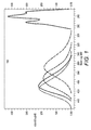
- FIG. 1 illustrates a graph 100 showing an incremental increase of mass average molecular mass (Mw) for the polymer thereby graphically illustrating the living nature of the polymer.
- a passivated carbon black dispersion was prepared. 325g stainless steel shot was added to an attritor. Then, this P(PFS/MI-b-PFS) (6g) was added to this and stirred at ⁇ 300 rpm. Subsequently, trifluorotoluene (TFT, 44g) was added and stirred for 10 minutes. Carbon black (Mogul E, 12g) was added to the stirred mixture, and the attritor was then stirred for 20 hours. The mixture was then sieved to give 43.8g of carbon black functionalized dispersion with PPFS. Solids analysis showed a carbon black content of 13.3%. The particle size was 245nm.
- FIG. 2 shows a particle size distribution of the resultant passivated carbon black particles formed in accordance with disclosed embodiments.
- the graph shows a particle size distribution with a peak at 245 nanometers.
Landscapes
- Chemical & Material Sciences (AREA)
- Organic Chemistry (AREA)
- Life Sciences & Earth Sciences (AREA)
- Engineering & Computer Science (AREA)
- Materials Engineering (AREA)
- Wood Science & Technology (AREA)
- Chemical Kinetics & Catalysis (AREA)
- General Chemical & Material Sciences (AREA)
- Health & Medical Sciences (AREA)
- Medicinal Chemistry (AREA)
- Polymers & Plastics (AREA)
- Compositions Of Macromolecular Compounds (AREA)
- Printing Plates And Materials Therefor (AREA)
- Graft Or Block Polymers (AREA)
- Pigments, Carbon Blacks, Or Wood Stains (AREA)
- Inks, Pencil-Leads, Or Crayons (AREA)
Abstract
Description
- This disclosure is related to carbon black-containing filler material. In particular, the disclosure relates to modified carbon black filler material suitable for use in various marking and printing methods and systems, such as variable data digital lithographic printing, among others.
- Lithography and offset lithography are common methods of printing today. The terms "printing," "marking" and "image forming" are used interchangeably in this disclosure. In a typical lithographic printing process an image transfer surface, which may be a flat plate, a surface of a cylinder or drum, a surface of a belt or the like is formed to have "image regions" formed of a hydrophobic/oleophilic material, and "non-image regions" formed of a hydrophilic/oleophobic material. The image regions correspond to the areas on the final print (i.e., the target image receiving media substrate) that are occupied by a printing or marking material such as ink to form images on the substrate. The non-image regions correspond to the areas on the final print that are not occupied by the printing or marking material. The hydrophilic regions accept and are readily wetted by surface preparation fluids, which may include water-based fluids or other compound fluids, that may be commonly referred to as dampening fluids or fountain solutions. These fluids conventionally consist of water and small amounts of alcohol and/or other additives and/or surfactants that are included to reduce surface tension of the fluids.
- The hydrophobic regions repel dampening fluid and accept ink, whereas the dampening fluid formed over the hydrophilic regions forms a fluid "release layer" for rejecting ink. The hydrophilic regions of the printing plate thus correspond to unprinted areas, or "non-image areas", of the final print.
- As indicated above, in varying conventional systems, the ink may be transferred directly to a target image receiving media substrate, such as paper, or may alternatively be applied to an intermediate image transfer surface, such as an offset (or blanket) cylinder in an offset printing system. Offset cylinders are often covered with conformable coatings or sleeves with surfaces that can conform to the texture of the target image receiving media substrate, which may have, for example, a surface peak-to-valley depth somewhat greater than the surface peak-to-valley depth of the imaging plate. Also, surface roughness of the offset (or blanket) cylinder helps to deliver a more uniform layer of the printing materials, including inks, to the target image receiving media substrates free of defects such as mottle. Sufficient pressure is used to transfer the image from the offset (or blanket) cylinder to the target image receiving media substrate. This pressure transfer often occurs at a transfer nip through which the target image receiving media substrate is pinched between the offset (or blanket) cylinder and an opposing pressure member, such as an impression cylinder, that provides the pressure on the non-image side of the target image receiving media substrate.
- Typical lithographic and offset printing techniques use plates that are permanently patterned, and are therefore useful only when printing a large number of copies of the same image (i.e., for long print runs), such as magazines, newspapers, and the like. These techniques are not generally considered useful in creating and printing documents in which new patterns are generated from one page to the next without removing and replacing the print cylinder and/or the imaging plate. In this regard, lithographic techniques cannot accommodate true high speed variable data printing in which the images change from impression to impression, for example, as in the case of digital printing systems. Furthermore, the cost of the permanently patterned imaging plates or cylinders is amortized over the number of copies. The cost per printed copy is therefore higher for shorter print runs of the same image than for longer print runs of the same image, as opposed to prints from digital printing systems.
- Based on the above shortfalls, a lithographic technique, referred to as variable data digital lithography, has been developed which uses a non-patterned reimageable surface on an imaging member. The process of image forming on the non-patterned reimageable surface commences with substantially uniformly coating the reimageable surface of the imaging member with a dampening fluid layer. Regions of the dampening fluid are removed by exposure to a focused radiation source, such as, for example, a laser light source, to form pockets. A temporary pattern in the dampening fluid is thus formed over the non-patterned reimageable surface. Ink applied to the patterned reimageable surface is retained in the pockets formed by the removing of the dampening fluid. The inked surface is then brought into contact with an image receiving media substrate, or an intermediate transfer surface at a transfer nip. The ink transfers from the pockets in the dampening fluid layer to the image receiving media substrate, or to the intermediate transfer surface for further transfer to an image receiving media substrate. Targeted transfer efficiencies for ink transfer from the reimageable surface are in a range of 95% or greater. In this process, residual ink and the dampening fluid may then be removed from the reimageable surface, a new uniform layer of dampening fluid may then applied to the reimageable surface, and the patterning, inking and transfer steps of the process repeated.
- Reimageable surfaces of the imaging members are formed of materials that have been experimentally determined to advantageously support the steps of the ink-based digital printing process. Such reimageable surface layers may be formed of, for example, a fluorosilicone and an infrared-absorbing filler. The fluorosilicone may include amino-functional groups. The filler may be selected from the group consisting of carbon black, iron oxide, carbon nanotubes, graphene, graphite, and carbon fibers.
- Alternative filler materials, or improvements to certain of the currently employed filler materials, that may present filler materials that are more suitable for use in the reimageable of imaging members in variable data digital lithography are desired.
- Carbon black is used as a filler material in a variety of polymeric materials and for different applications. Carbon black is commonly added to impart thermal and/or electrical conductivity. Carbon black is also used as a light absorbing particle.
- If a polymer matrix is hydrophobic, and especially if it is fluorinated, as are certain of the materials from which the reimageable surfaces of the imaging members for the above-discussed variable data digital lithographic image forming processes are formed, compatibility of carbon black in the polymer matrix is an issue. Problems with carbon black compatibility tend to manifest themselves detrimentally in the form of particle agglomeration and particle shedding from the matrix. Incompatibility may lead to poor mechanical properties and/or requirements of high loading to obtain desired thermal, electrical and/or optical properties. Particles may be ground using various milling techniques to a fine particle size. Incompatibility with the matrix, however, may generally result in re-agglomeration re-introducing the difficulties listed above.
- Exemplary embodiments according to this disclosure may provide passivated carbon black particles suitable for use as polymeric fillers. In particular embodiments, poly-(pentafluorostyrene/Maleimide-b-pentafluorostyrene) passivated carbon black particles suitable as polymeric filler are provided.
- In embodiments, surface passivation of carbon black particles is provided via the use of an A/B-block copolymer where the A/B block contains a pentafluorostyrene-maleimide alternating polymer and the B block contains pure pentafluorostyrene.
- In embodiments, the A/B portion allows for the polymer to adsorb onto the carbon black filler particles while the b-block acts as a stabilizer in fluorinated systems. Fine dispersions result from the addition of poly (pentafluorostyrene/Maleimide-b-pentafluorostyrene) or P(PFS/MI-b-PFS) passivated carbon black to fluorinated polymers, enhancing the physical and mechanical properties.
- In embodiments, the disclosed passivating schemes allow for the passivation via an absorption process that does not require heating to above 120°C and may allow for the use of lower boiling fluorinated media.
- Exemplary embodiments may provide particulate filler comprising at least one of functionalized carbon black particles, carbon nanotubes, graphite particles and carbon fibers.
- The disclosed surface passivated carbon black particles may find particular utility in incorporation into reimageable surfaces of the imaging members employed for the above-described variable data digital image forming operations. The surface passivated carbon black particles provided by this disclosure may be useful for other applications in addition to offset printing, such as fillers for fusing members or for solid ink printing transfer drums.
- Exemplary embodiments are described herein. It is envisioned, however, that any composition, apparatus, method, or system that incorporates features of this disclosure is encompassed by the scope and spirit of the exemplary embodiments.
-
-
FIG. 1 illustrates a graph showing an incremental increase of mass average molecular mass (Mw) for the polymers prepared according to this disclosure; and -
FIG. 2 illustrates a graph showing particle size dispersion, by volume, of functionalized carbon black particles according to this disclosure. - Exemplary embodiments are intended to cover all alternatives, modifications, and equivalents as may be included within the spirit and scope of the compositions, methods, and systems as described below.
- The modifiers "about" and/or "substantially" used in connection with any quantity or feature are intended to be inclusive of any stated values and as having a meaning dictated by the context (for example, these modifiers are used to include at least the degree of error associated with any measurement or feature that may be considered reasonable and the particular context). When used with a specific value, the use of the modifier "about" should also be considered as disclosing that specific value.
- Reference is made to the drawings to accommodate understanding of filler compositions, methods, and systems in accordance with embodiments, particularly functionalized carbon black for use with variable data digital lithography printing system components such as imaging member filler. "Variable data lithography printing," or "ink-based digital printing," or "digital offset printing" are terms that are used essentially interchangeably throughout this disclosure to connote lithographic printing of variable image data for producing images on individual image receiving media substrates in which the images are changeable with each subsequent rendering of the images on sequential substrates in the image forming process. "Variable data digital lithographic printing" includes offset printing of ink images using lithographic ink in which the images are based on digital image data that may vary from image to image. Ink-based digital printing uses a variable data lithography printing system, or digital offset printing system. A "variable data digital lithography system" is a system that is configured for lithographic printing using lithographic inks and based on digital image data, which may be variable from one image to the next.
- An imaging member surface, and particularly a reimageable surface of an imaging member as discussed above, generally has a tailored topology, a micro-roughened surface structured to retain a uniform layer of dampening fluid in non-image areas following imaging via an imaging device, as described above. Hillocks and pits that constitute the micro-roughened surface enhance the static or dynamic surface energy forces that may attract the dampening fluid to the reimageable surface. This reduces the tendency of the dampening fluid to be forced away from the reimageable surface by roller nip action, for example.
- The imaging member plays multiple roles in the variable data digital lithography printing process. These roles may include: (1) wetting with a uniform layer of dampening fluid, (2) creation of a latent image through image wise patterning of the uniform layer of dampening fluid, (3) inking with an offset ink, and (4) enabling the ink to lift off and be transferred to an image receiving media substrate, while retaining surface adhesion of the patterned layer of dampening fluid.
- Some desirable qualities for the reimageable surface of the imaging member, include high tensile strength to increase the useful service lifetime of the imaging member. The surface layer should also weakly adhere to the ink, yet be wettable with the ink, to promote both uniform inking of image areas and to promote subsequent transfer of the ink from the surface to the image receiving media substrate. Finally, some solvents have such an affinity for the imaging member that they inevitably cause some swelling of the reimageable surface of the imaging member. Wear can proceed indirectly under these swell conditions by causing the release of near infrared laser energy-absorbing particles at the imaging member surface, which then act as abrasive particles. Desirably, the imaging member surface layer has a low tendency to be penetrated by solvent and a high tendency for retention of energy absorbing particles.
- An imaging member that meets these requirements may include a surface having fluorosilicone and an infrared-absorbing filler. The term "fluorosilicone" as used in this disclosure refers generally to polyorganosiloxanes having a backbone formed from silicon and oxygen atoms and sidechains containing carbon, hydrogen, and fluorine atoms. At least one fluorine atom is present in the sidechain. The sidechains can be linear, branched, cyclic, or aromatic. The fluorosilicone may also contain functional groups, such as amino groups, which permit additional crosslinking. When the crosslinking is complete, such groups become part of the backbone of the overall fluorosilicone. Fluorosilicones are commercially available, as, for example, CF1-3510 from NuSil.
- The infrared-absorbing filler may absorb energy from the infra-red portion of the electromagnetic spectrum (having a wavelength of from about 750 nm to about 1000 nm). This aids in efficient interaction of the energy radiated from the image wise patterning device (i.e., a laser) and the dampening fluid. The infrared-absorbing filler may be carbon black, a metal oxide such as iron oxide (FeO), carbon nanotubes, graphene, graphite, or carbon fibers.
- A filler particle in accordance with embodiments of this disclosure includes surface passivated carbon black particles. It is important that filler particles do not negatively impact surface interactions when used in, for example, the reimageable surface of an imaging member during printing operations where surface contamination may result in print defects or system or operation failure. Adhesion sites, or sites of high surface energy, may be formed on a filler particle surface that causes such interactions. The impact of these interactions may be minimized or reduced by functionalizing the particles with passivating molecules. Further, functionalized particles may allow for fine dispersion of the filler particles in a polymer matrix, which enhance physical interactions such as optical absorption. Fine dispersion also enables improved compatibility in a polymer matrix which enhances mechanical properties.
- Filler particles in accordance with embodiments may include carbon black particles that are surface passivated by way of poly (pentafluorostyrene/Maleimide-b-pentafluorostyrene) or P(PFS/MI-b-PFS) block copolymer being adsorbed onto the surface of the carbon black particles. Carbon black is known, and is known to be useful as a filler material in many uses including in imaging member surfaces. Carbon black is generally produced by the incomplete combustion of hydrocarbons, or by charring of other organic materials. Carbon black is commercially available from one of several different sources.
- According to the disclosed schemes, the preparation of an A/B-b-block copolymer is made by a living radical polymerization. Styrenics have a tendency to complex with maleic or maleimide molecules and the polymerization yields a perfectly alternating styrenic/maleic type copolymer. In the living radical polymerization system, the styrenic/maleic monomers are consumed first. Subsequently, in the presence of excess styrenic monomer, the polymer continues to grow resulting in a P(PFS/MI-b-PFS) block copolymer. This P(PFS/MI-b-PFS) block copolymer is then incorporated in a dispersion system and the maleimide moiety adsorbs onto the carbon black particles while the PFS tail gives dispersability in the fluorinated system. Carbon black particles that are passivated by P(PFS/MI-b-PFS) polymers when adsorbed onto the surface result in a robust treatment that renders the carbon black particles. The composition of the surface functionalized carbon black particles is new.

- Functionalized carbon black particles in accordance with embodiments are suitable for fine dispersion in solvent for subsequent processing. Further, the carbon black particle composition in accordance with embodiments is suitable for dispersion in fluorinated polymers, and enables enhanced properties of carbon black and polymeric composites by enabling small particle size and fine dispersion.
- P(PFS/MI-b-PFS) functionalized particles are suitable for incorporation into fluorinated polymeric media. Particles could be readily incorporated into polymers such as fluorosilicones, polyvinylfluoride, polytetrafluoroethylene, perfluoroalkoxyfluoropolymer (PFA-teflon), FKM polymer (such as VITON), fluorinated ethylene-propylene (FEP), or other fluoropolymers. The robustness of the surface treatment is advantageous for high temperature processing techniques such as melt mixing. Incorporation of these particles into various media may be advantageous in printing and document processing applications including fusing, solid ink printing, and ink-based digital printing, for example.
- For example, filler compositions and particles of embodiments may be used to form a reimageable surface for an imaging member for an ink-based digital printing system. An imaging member for offset printing may include fluorosilicone comprising siloxane units. At least about 75% of the siloxane units may be fluorinated. The imaging member may include a surface layer having a fluorosilicone and an infrared-absorbing filler composition rendered in accordance with embodiments. The fluorosilicone may include amino-functional groups, and the filler may be present in an amount of from 5 to 40 weight percent, or from 10 to 30 weight percent, or from 15 to 25 weight percent. The filler may be functionalized carbon black in accordance with filler compositions of embodiments.
- Methods of manufacturing an imaging member surface layer may include depositing a surface layer composition upon a mold, and curing the surface layer at an elevated temperature. The curing may be conducted at a temperature of from about 135°C to about 165°C. Optionally, the surface layer composition may comprise a catalyst such as platinum. The cured surface layer may have a thickness of from 1 micron to 4 millimeters, or from 5 microns to 1 millimeter, or from 10 microns to 50 microns.
- The cured surface layer may be confined to a thickness of less than 50 microns, or less than 20 microns, or in an optimal configuration, less than 10 microns, for the purpose that the near infrared radiation will be confined to the narrow topcoat layer for maximum thermal absorption and temperature increase. A sharp increase in temperature is necessary for the evaporation of dampening fluid during imaging.
- A dampening fluid useful with an imaging member surface having the disclosed filler may include a fluid comprising a siloxane compound. The siloxane compound may be octamethylcyclotetrasiloxane (D4).
- The imaging surface layer may display a surface roughness with an Ra in a range of from 0.2 microns to 2 microns, or from 0.3 microns to 1 micron, or from 0.5 microns to 0.8 microns. The surface roughness may be spontaneously formed upon curing, or formed via a subtractive process from the surface, such as chemical etching, plasma etching, or surface roughening.
- Aspects of the present disclosure may be further understood by referring to the following example. Filler compositions comprising functionalized carbon black were produced that comprised hydrophobic carbon black particles passivated with P(PFS/MI-b-PFS). The carbon black particles had a diameter in a range of 50 nanometers to 1 micron, and enabled dispersion in fluorinated polymers, and fine dispersion in solvent. The example is illustrative only.
- P(PFS/MI-b-PFS) was prepared. Pentafluorostyrene (24.2g), maleimide (1.33g) and 2, 2, 6, 6-tetramethyl-piperidine-1-oxyl (TEMPO, 0.119g, .00075 mol) were added to a round bottom flask equipped with a reflux condenser, nitrogen inlet. This was then degassed with nitrogen gas for 10 minutes and then VAZO 67 (0.095g, 0.0005 mol) was added. The solution was then heated, while under nitrogen gas, to a bath temperature of 138°C. After the bath temperature was attained, VAZO 88 (0.015g) was added added at 30, 60, 120,180 and 260 minutes. The solution was heated for 7 hours and then cooled. After cooling, tetrahydrofuran (THF) was added (10mL) and then this solution was added to methanol (200mL) to afford a poly (pentafluorostyrene/maleimide)-b-pentafluorostyrene-TEMPO terminated P(PFS/MI-b-PFS) polymer (8.5g).
-
FIG. 1 illustrates agraph 100 showing an incremental increase of mass average molecular mass (Mw) for the polymer thereby graphically illustrating the living nature of the polymer. - A passivated carbon black dispersion was prepared. 325g stainless steel shot was added to an attritor. Then, this P(PFS/MI-b-PFS) (6g) was added to this and stirred at ∼300 rpm. Subsequently, trifluorotoluene (TFT, 44g) was added and stirred for 10 minutes. Carbon black (Mogul E, 12g) was added to the stirred mixture, and the attritor was then stirred for 20 hours. The mixture was then sieved to give 43.8g of carbon black functionalized dispersion with PPFS. Solids analysis showed a carbon black content of 13.3%. The particle size was 245nm.
-
FIG. 2 shows a particle size distribution of the resultant passivated carbon black particles formed in accordance with disclosed embodiments. The graph shows a particle size distribution with a peak at 245 nanometers. - The present disclosure has been described with reference to exemplary embodiments. Modifications and alterations will occur to others upon reading and understanding the preceding detailed description. It is intended that the present disclosure be construed as including all such modifications and alterations insofar as they come within the scope of the appended claims or the equivalents thereof.
Claims (10)
- A particulate filler composition useful for print systems applications, comprising functionalized infra-red absorbing particulates, the infra-red absorbing particulates being functionalized by adsorbing a polymer onto the surface of the infra-red absorbing particulates to surface passivate the infra-red absorbing particulates.
- The particulate filler composition of claim 1, the infra-red absorbing particulates comprising carbon black particles.
- The particulate filler composition of claim 2, the polymer comprising poly-(pentafluorostyrene/Maleimide-b-pentafluorostyrene) (P(PFS/MI-b-PFS)).
- The particulate filler composition of claim 2, the polymer being prepared by a living radical polymerization.
- The particulate filler composition of claim 4, the polymer being an A/B-b-block copolymer.
- The particulate filler composition of claim 1, the infra-red absorbing particulates having a diameter of less than 1 micron.
- The particulate filler composition of claim 1, the infra-red absorbing particulates being configured for dispersion in fluorinated polymer.
- The particulate filler composition of claim 1, the infra-red absorbing particulates being functionalized to be hydrophobic.
- A method for producing a particulate filler composition, comprising:providing P(PFS/MI-b-PFS) in a vessel;stirring an organic fluorocarbon into the vessel;adding carbon black particles to the vessel;stirring the vessel for a first extended time period; andsieving a resulting mixture to provide a functionalized carbon black as a produced particulate filler composition.
- The method of claim 9, further comprising pre-preparing the P(PFS/MI-b-PFS) byproviding pentafluorostyrene in a flask;adding maleimide to the flask;adding a polymer-supported catalyst to the flask; degassing the flask;adding a first free radical source to the flask; heating the solution under nitrogen gas to a pre-determined bath temperature;maintaining the pre-determined bath temperature for a second extended time period;periodically adding a second free radical source; cooling the solution;adding a cyclic ether; andadding the solution to methanol to provide the P(PFS/MI-b-PFS).
Applications Claiming Priority (1)
| Application Number | Priority Date | Filing Date | Title |
|---|---|---|---|
| US14/922,125 US9567470B1 (en) | 2015-10-24 | 2015-10-24 | Carbon black polymeric filler useful for printing applications |
Publications (2)
| Publication Number | Publication Date |
|---|---|
| EP3168265A1 true EP3168265A1 (en) | 2017-05-17 |
| EP3168265B1 EP3168265B1 (en) | 2020-07-01 |
Family
ID=57218684
Family Applications (1)
| Application Number | Title | Priority Date | Filing Date |
|---|---|---|---|
| EP16192919.5A Active EP3168265B1 (en) | 2015-10-24 | 2016-10-07 | Carbon black polymeric filler useful for printing applications |
Country Status (3)
| Country | Link |
|---|---|
| US (1) | US9567470B1 (en) |
| EP (1) | EP3168265B1 (en) |
| JP (1) | JP6622676B2 (en) |
Families Citing this family (3)
| Publication number | Priority date | Publication date | Assignee | Title |
|---|---|---|---|---|
| FR3097689B1 (en) * | 2019-06-19 | 2021-06-25 | Commissariat Energie Atomique | Method of forming an electroconductive hydrophobic microporous layer useful as a gas diffusion layer |
| JPWO2021192900A1 (en) * | 2020-03-27 | 2021-09-30 | ||
| CN113462105A (en) * | 2021-05-31 | 2021-10-01 | 浙江科赛新材料科技有限公司 | Expanded polytetrafluoroethylene material and preparation method thereof |
Citations (4)
| Publication number | Priority date | Publication date | Assignee | Title |
|---|---|---|---|---|
| WO2000042084A1 (en) * | 1999-01-12 | 2000-07-20 | Jotun A/S | Block copolymers with perfluorinated side-chain blocks and the preparation thereof |
| EP1428673A1 (en) * | 2002-12-09 | 2004-06-16 | Xerox Corporation | Phase change ink imaging component with nano-size filler |
| US20150092004A1 (en) * | 2013-09-30 | 2015-04-02 | Xerox Corporation | Methods for forming functionalized carbon black with amino-terminated polyfluorodimethylsiloxane for printing |
| DE102015220451A1 (en) * | 2014-11-03 | 2016-05-04 | Xerox Corporation | Carbon black polymer filler useful for printing applications |
Family Cites Families (2)
| Publication number | Priority date | Publication date | Assignee | Title |
|---|---|---|---|---|
| KR100267191B1 (en) * | 1995-06-14 | 2000-11-01 | 다나카 쇼소 | Carbon black graft polymer, process for the production of the polymer and use thereof |
| JP2014077073A (en) * | 2012-10-11 | 2014-05-01 | Asahi Glass Co Ltd | Novel polymer, method of producing the same and plastic optical fiber |
-
2015
- 2015-10-24 US US14/922,125 patent/US9567470B1/en not_active Expired - Fee Related
-
2016
- 2016-10-07 JP JP2016199247A patent/JP6622676B2/en not_active Expired - Fee Related
- 2016-10-07 EP EP16192919.5A patent/EP3168265B1/en active Active
Patent Citations (4)
| Publication number | Priority date | Publication date | Assignee | Title |
|---|---|---|---|---|
| WO2000042084A1 (en) * | 1999-01-12 | 2000-07-20 | Jotun A/S | Block copolymers with perfluorinated side-chain blocks and the preparation thereof |
| EP1428673A1 (en) * | 2002-12-09 | 2004-06-16 | Xerox Corporation | Phase change ink imaging component with nano-size filler |
| US20150092004A1 (en) * | 2013-09-30 | 2015-04-02 | Xerox Corporation | Methods for forming functionalized carbon black with amino-terminated polyfluorodimethylsiloxane for printing |
| DE102015220451A1 (en) * | 2014-11-03 | 2016-05-04 | Xerox Corporation | Carbon black polymer filler useful for printing applications |
Non-Patent Citations (5)
| Title |
|---|
| A. ERCEG , R. VUKOVIC , G. BOGDANIC & D. FLES: "FREE RADICAL-INITIATED COPOLYMERIZATION OF 2,6-DICHLOROSTYRENE WITH MALEIMIDE, N-METHYLMALEIMIDE, AND N-PHENYLMALEIMIDE", JOURNAL OF MACROMOLECULAR SCIENCE, PART A, vol. 37, no. 5, 7 February 2007 (2007-02-07), pages 513 - 524, XP002768295, ISSN: 1520-5738, DOI: 10.1081/MA-100101107 * |
| MIRELA ZAMFIR & JEAN-FRANÇOIS LUTZ: "Ultra-precise insertion of functional monomers in chain-growth polymerizations", NATURE COMMUNICATIONS, vol. 3, 1138, 16 October 2012 (2012-10-16), XP002768293, DOI: 10.1038/ncomms2151 * |
| SEBASTIAN PFEIFER & JEAN-FRANCOIS LUTZ: "Supporting Information: A Facile Procedure for Controlling Monomer Sequence Distribution in Radical Chain Polymerizations", 17 July 2007 (2007-07-17), Retrieved from the Internet <URL:http://pubs.acs.org/doi/suppl/10.1021/ja0717616> [retrieved on 20170317] * |
| SEBASTIAN PFEIFER AND JEAN-FRANCOIS LUTZ: "A Facile Procedure for Controlling Monomer Sequence Distribution in RadicalChain Polymerizations", J. AM. CHEM. SOC, vol. 129, 2007, pages 9542 - 9543, XP002768294, DOI: 10.1021/ja0717616 * |
| SHINJI HAYASHI, ATSUSHI NAITOH, SEIICHI MACHIDA, MASAKI OKAZAKI, KIYOTAKA MARUYAMA AND NORIO TSUBOKAWA: "Grafting of Polymers onto a Carbon BlackSurface by the Trapping of Polymer Radicals", APPLIED ORGANOMETALLIC CHEMISTRY, vol. 12, 1998, pages 743 - 748, XP002768292 * |
Also Published As
| Publication number | Publication date |
|---|---|
| JP6622676B2 (en) | 2019-12-18 |
| US9567470B1 (en) | 2017-02-14 |
| JP2017081156A (en) | 2017-05-18 |
| EP3168265B1 (en) | 2020-07-01 |
Similar Documents
| Publication | Publication Date | Title |
|---|---|---|
| CN107540842B (en) | Stabilizer against toxic material emissions in imaging plates or intermediate blanket materials | |
| US20160122549A1 (en) | Carbon black polymeric filler useful for printing applications | |
| US9283795B1 (en) | Imaging member for offset printing applications | |
| US9592698B2 (en) | Imaging member for offset printing applications | |
| CA2875529C (en) | Methods for ink-based digital printing with high ink transfer efficiency | |
| CN105885523B (en) | Hyperbranched ink compositions for controlled dimensional change and low energy curing | |
| US9561677B2 (en) | Imaging member for offset printing applications | |
| EP3168265B1 (en) | Carbon black polymeric filler useful for printing applications | |
| EP2868482A2 (en) | Imaging blanket with dispersed carbon and micro-texture surface | |
| US6184267B1 (en) | Oil-based ink for preparing printing plate by ink jet process and method for preparing printing plate by ink jet process | |
| US11767447B2 (en) | Topcoat composition of imaging blanket with improved properties | |
| US6127452A (en) | Oil-based ink for printing plate by ink jet process and method for preparing printing plate by ink jet process | |
| EP3159741A1 (en) | Digital lithographic image forming surface incorporating a carbon black polymeric filler | |
| US9469143B1 (en) | Digital lithographic image forming surface incorporating a carbon black polymeric filler | |
| US6143806A (en) | Oil-based ink for preparing printing plate by ink jet process and method for preparing printing plate by ink jet process | |
| US6080449A (en) | Oil-based ink for preparing printing plate by ink jet process and method for preparing printing plate by ink jet process | |
| US6140389A (en) | Oil-based ink for printing plate by ink jet process and method for preparing printing plate by ink jet process | |
| An et al. | Preparation of a Near-Infrared Light-Sensitive Coating Based on Fluorine-Containing Polymer Emulsion | |
| US20220049123A1 (en) | Topcoat composition of imaging blanket for reducing coating defects | |
| CN120941871A (en) | A nanocomposite material modified high-sensitivity, pre-processed negative CTP plate and its preparation method | |
| JPH10298479A (en) | Oil-base ink for ink jet process printing plate | |
| JPH11269415A (en) | Oil-base ink for ink jet process printing plate and method for forming printing plate by using same | |
| JP2000327971A (en) | Oily ink for electrostatic ink jet |
Legal Events
| Date | Code | Title | Description |
|---|---|---|---|
| PUAI | Public reference made under article 153(3) epc to a published international application that has entered the european phase |
Free format text: ORIGINAL CODE: 0009012 |
|
| STAA | Information on the status of an ep patent application or granted ep patent |
Free format text: STATUS: THE APPLICATION HAS BEEN PUBLISHED |
|
| AK | Designated contracting states |
Kind code of ref document: A1 Designated state(s): AL AT BE BG CH CY CZ DE DK EE ES FI FR GB GR HR HU IE IS IT LI LT LU LV MC MK MT NL NO PL PT RO RS SE SI SK SM TR |
|
| AX | Request for extension of the european patent |
Extension state: BA ME |
|
| STAA | Information on the status of an ep patent application or granted ep patent |
Free format text: STATUS: REQUEST FOR EXAMINATION WAS MADE |
|
| 17P | Request for examination filed |
Effective date: 20171117 |
|
| RBV | Designated contracting states (corrected) |
Designated state(s): AL AT BE BG CH CY CZ DE DK EE ES FI FR GB GR HR HU IE IS IT LI LT LU LV MC MK MT NL NO PL PT RO RS SE SI SK SM TR |
|
| GRAP | Despatch of communication of intention to grant a patent |
Free format text: ORIGINAL CODE: EPIDOSNIGR1 |
|
| STAA | Information on the status of an ep patent application or granted ep patent |
Free format text: STATUS: GRANT OF PATENT IS INTENDED |
|
| GRAJ | Information related to disapproval of communication of intention to grant by the applicant or resumption of examination proceedings by the epo deleted |
Free format text: ORIGINAL CODE: EPIDOSDIGR1 |
|
| STAA | Information on the status of an ep patent application or granted ep patent |
Free format text: STATUS: REQUEST FOR EXAMINATION WAS MADE |
|
| INTG | Intention to grant announced |
Effective date: 20191219 |
|
| GRAP | Despatch of communication of intention to grant a patent |
Free format text: ORIGINAL CODE: EPIDOSNIGR1 |
|
| STAA | Information on the status of an ep patent application or granted ep patent |
Free format text: STATUS: GRANT OF PATENT IS INTENDED |
|
| INTC | Intention to grant announced (deleted) | ||
| INTG | Intention to grant announced |
Effective date: 20200124 |
|
| GRAS | Grant fee paid |
Free format text: ORIGINAL CODE: EPIDOSNIGR3 |
|
| GRAA | (expected) grant |
Free format text: ORIGINAL CODE: 0009210 |
|
| STAA | Information on the status of an ep patent application or granted ep patent |
Free format text: STATUS: THE PATENT HAS BEEN GRANTED |
|
| AK | Designated contracting states |
Kind code of ref document: B1 Designated state(s): AL AT BE BG CH CY CZ DE DK EE ES FI FR GB GR HR HU IE IS IT LI LT LU LV MC MK MT NL NO PL PT RO RS SE SI SK SM TR |
|
| REG | Reference to a national code |
Ref country code: CH Ref legal event code: EP Ref country code: AT Ref legal event code: REF Ref document number: 1286163 Country of ref document: AT Kind code of ref document: T Effective date: 20200715 |
|
| REG | Reference to a national code |
Ref country code: IE Ref legal event code: FG4D |
|
| REG | Reference to a national code |
Ref country code: DE Ref legal event code: R096 Ref document number: 602016039017 Country of ref document: DE |
|
| REG | Reference to a national code |
Ref country code: LT Ref legal event code: MG4D |
|
| PG25 | Lapsed in a contracting state [announced via postgrant information from national office to epo] |
Ref country code: BG Free format text: LAPSE BECAUSE OF FAILURE TO SUBMIT A TRANSLATION OF THE DESCRIPTION OR TO PAY THE FEE WITHIN THE PRESCRIBED TIME-LIMIT Effective date: 20201001 |
|
| REG | Reference to a national code |
Ref country code: NL Ref legal event code: MP Effective date: 20200701 |
|
| REG | Reference to a national code |
Ref country code: AT Ref legal event code: MK05 Ref document number: 1286163 Country of ref document: AT Kind code of ref document: T Effective date: 20200701 |
|
| PG25 | Lapsed in a contracting state [announced via postgrant information from national office to epo] |
Ref country code: CZ Free format text: LAPSE BECAUSE OF FAILURE TO SUBMIT A TRANSLATION OF THE DESCRIPTION OR TO PAY THE FEE WITHIN THE PRESCRIBED TIME-LIMIT Effective date: 20200701 Ref country code: GR Free format text: LAPSE BECAUSE OF FAILURE TO SUBMIT A TRANSLATION OF THE DESCRIPTION OR TO PAY THE FEE WITHIN THE PRESCRIBED TIME-LIMIT Effective date: 20201002 Ref country code: NO Free format text: LAPSE BECAUSE OF FAILURE TO SUBMIT A TRANSLATION OF THE DESCRIPTION OR TO PAY THE FEE WITHIN THE PRESCRIBED TIME-LIMIT Effective date: 20201001 Ref country code: FI Free format text: LAPSE BECAUSE OF FAILURE TO SUBMIT A TRANSLATION OF THE DESCRIPTION OR TO PAY THE FEE WITHIN THE PRESCRIBED TIME-LIMIT Effective date: 20200701 Ref country code: LT Free format text: LAPSE BECAUSE OF FAILURE TO SUBMIT A TRANSLATION OF THE DESCRIPTION OR TO PAY THE FEE WITHIN THE PRESCRIBED TIME-LIMIT Effective date: 20200701 Ref country code: PT Free format text: LAPSE BECAUSE OF FAILURE TO SUBMIT A TRANSLATION OF THE DESCRIPTION OR TO PAY THE FEE WITHIN THE PRESCRIBED TIME-LIMIT Effective date: 20201102 Ref country code: HR Free format text: LAPSE BECAUSE OF FAILURE TO SUBMIT A TRANSLATION OF THE DESCRIPTION OR TO PAY THE FEE WITHIN THE PRESCRIBED TIME-LIMIT Effective date: 20200701 Ref country code: AT Free format text: LAPSE BECAUSE OF FAILURE TO SUBMIT A TRANSLATION OF THE DESCRIPTION OR TO PAY THE FEE WITHIN THE PRESCRIBED TIME-LIMIT Effective date: 20200701 Ref country code: SE Free format text: LAPSE BECAUSE OF FAILURE TO SUBMIT A TRANSLATION OF THE DESCRIPTION OR TO PAY THE FEE WITHIN THE PRESCRIBED TIME-LIMIT Effective date: 20200701 Ref country code: ES Free format text: LAPSE BECAUSE OF FAILURE TO SUBMIT A TRANSLATION OF THE DESCRIPTION OR TO PAY THE FEE WITHIN THE PRESCRIBED TIME-LIMIT Effective date: 20200701 |
|
| PG25 | Lapsed in a contracting state [announced via postgrant information from national office to epo] |
Ref country code: PL Free format text: LAPSE BECAUSE OF FAILURE TO SUBMIT A TRANSLATION OF THE DESCRIPTION OR TO PAY THE FEE WITHIN THE PRESCRIBED TIME-LIMIT Effective date: 20200701 Ref country code: LV Free format text: LAPSE BECAUSE OF FAILURE TO SUBMIT A TRANSLATION OF THE DESCRIPTION OR TO PAY THE FEE WITHIN THE PRESCRIBED TIME-LIMIT Effective date: 20200701 Ref country code: RS Free format text: LAPSE BECAUSE OF FAILURE TO SUBMIT A TRANSLATION OF THE DESCRIPTION OR TO PAY THE FEE WITHIN THE PRESCRIBED TIME-LIMIT Effective date: 20200701 Ref country code: IS Free format text: LAPSE BECAUSE OF FAILURE TO SUBMIT A TRANSLATION OF THE DESCRIPTION OR TO PAY THE FEE WITHIN THE PRESCRIBED TIME-LIMIT Effective date: 20201101 |
|
| PG25 | Lapsed in a contracting state [announced via postgrant information from national office to epo] |
Ref country code: NL Free format text: LAPSE BECAUSE OF FAILURE TO SUBMIT A TRANSLATION OF THE DESCRIPTION OR TO PAY THE FEE WITHIN THE PRESCRIBED TIME-LIMIT Effective date: 20200701 |
|
| REG | Reference to a national code |
Ref country code: DE Ref legal event code: R097 Ref document number: 602016039017 Country of ref document: DE |
|
| PG25 | Lapsed in a contracting state [announced via postgrant information from national office to epo] |
Ref country code: EE Free format text: LAPSE BECAUSE OF FAILURE TO SUBMIT A TRANSLATION OF THE DESCRIPTION OR TO PAY THE FEE WITHIN THE PRESCRIBED TIME-LIMIT Effective date: 20200701 Ref country code: IT Free format text: LAPSE BECAUSE OF FAILURE TO SUBMIT A TRANSLATION OF THE DESCRIPTION OR TO PAY THE FEE WITHIN THE PRESCRIBED TIME-LIMIT Effective date: 20200701 Ref country code: SM Free format text: LAPSE BECAUSE OF FAILURE TO SUBMIT A TRANSLATION OF THE DESCRIPTION OR TO PAY THE FEE WITHIN THE PRESCRIBED TIME-LIMIT Effective date: 20200701 Ref country code: RO Free format text: LAPSE BECAUSE OF FAILURE TO SUBMIT A TRANSLATION OF THE DESCRIPTION OR TO PAY THE FEE WITHIN THE PRESCRIBED TIME-LIMIT Effective date: 20200701 Ref country code: DK Free format text: LAPSE BECAUSE OF FAILURE TO SUBMIT A TRANSLATION OF THE DESCRIPTION OR TO PAY THE FEE WITHIN THE PRESCRIBED TIME-LIMIT Effective date: 20200701 |
|
| PLBE | No opposition filed within time limit |
Free format text: ORIGINAL CODE: 0009261 |
|
| STAA | Information on the status of an ep patent application or granted ep patent |
Free format text: STATUS: NO OPPOSITION FILED WITHIN TIME LIMIT |
|
| PG25 | Lapsed in a contracting state [announced via postgrant information from national office to epo] |
Ref country code: AL Free format text: LAPSE BECAUSE OF FAILURE TO SUBMIT A TRANSLATION OF THE DESCRIPTION OR TO PAY THE FEE WITHIN THE PRESCRIBED TIME-LIMIT Effective date: 20200701 |
|
| REG | Reference to a national code |
Ref country code: CH Ref legal event code: PL |
|
| 26N | No opposition filed |
Effective date: 20210406 |
|
| PG25 | Lapsed in a contracting state [announced via postgrant information from national office to epo] |
Ref country code: LU Free format text: LAPSE BECAUSE OF NON-PAYMENT OF DUE FEES Effective date: 20201007 Ref country code: MC Free format text: LAPSE BECAUSE OF FAILURE TO SUBMIT A TRANSLATION OF THE DESCRIPTION OR TO PAY THE FEE WITHIN THE PRESCRIBED TIME-LIMIT Effective date: 20200701 Ref country code: SK Free format text: LAPSE BECAUSE OF FAILURE TO SUBMIT A TRANSLATION OF THE DESCRIPTION OR TO PAY THE FEE WITHIN THE PRESCRIBED TIME-LIMIT Effective date: 20200701 |
|
| REG | Reference to a national code |
Ref country code: BE Ref legal event code: MM Effective date: 20201031 |
|
| PG25 | Lapsed in a contracting state [announced via postgrant information from national office to epo] |
Ref country code: CH Free format text: LAPSE BECAUSE OF NON-PAYMENT OF DUE FEES Effective date: 20201031 Ref country code: BE Free format text: LAPSE BECAUSE OF NON-PAYMENT OF DUE FEES Effective date: 20201031 Ref country code: SI Free format text: LAPSE BECAUSE OF FAILURE TO SUBMIT A TRANSLATION OF THE DESCRIPTION OR TO PAY THE FEE WITHIN THE PRESCRIBED TIME-LIMIT Effective date: 20200701 Ref country code: LI Free format text: LAPSE BECAUSE OF NON-PAYMENT OF DUE FEES Effective date: 20201031 |
|
| PG25 | Lapsed in a contracting state [announced via postgrant information from national office to epo] |
Ref country code: IE Free format text: LAPSE BECAUSE OF NON-PAYMENT OF DUE FEES Effective date: 20201007 |
|
| PG25 | Lapsed in a contracting state [announced via postgrant information from national office to epo] |
Ref country code: TR Free format text: LAPSE BECAUSE OF FAILURE TO SUBMIT A TRANSLATION OF THE DESCRIPTION OR TO PAY THE FEE WITHIN THE PRESCRIBED TIME-LIMIT Effective date: 20200701 Ref country code: MT Free format text: LAPSE BECAUSE OF FAILURE TO SUBMIT A TRANSLATION OF THE DESCRIPTION OR TO PAY THE FEE WITHIN THE PRESCRIBED TIME-LIMIT Effective date: 20200701 Ref country code: CY Free format text: LAPSE BECAUSE OF FAILURE TO SUBMIT A TRANSLATION OF THE DESCRIPTION OR TO PAY THE FEE WITHIN THE PRESCRIBED TIME-LIMIT Effective date: 20200701 |
|
| PG25 | Lapsed in a contracting state [announced via postgrant information from national office to epo] |
Ref country code: MK Free format text: LAPSE BECAUSE OF FAILURE TO SUBMIT A TRANSLATION OF THE DESCRIPTION OR TO PAY THE FEE WITHIN THE PRESCRIBED TIME-LIMIT Effective date: 20200701 |
|
| PGFP | Annual fee paid to national office [announced via postgrant information from national office to epo] |
Ref country code: GB Payment date: 20230920 Year of fee payment: 8 |
|
| PGFP | Annual fee paid to national office [announced via postgrant information from national office to epo] |
Ref country code: FR Payment date: 20230920 Year of fee payment: 8 |
|
| PGFP | Annual fee paid to national office [announced via postgrant information from national office to epo] |
Ref country code: DE Payment date: 20230920 Year of fee payment: 8 |
|
| REG | Reference to a national code |
Ref country code: DE Ref legal event code: R119 Ref document number: 602016039017 Country of ref document: DE |
|
| GBPC | Gb: european patent ceased through non-payment of renewal fee |
Effective date: 20241007 |
|
| PG25 | Lapsed in a contracting state [announced via postgrant information from national office to epo] |
Ref country code: DE Free format text: LAPSE BECAUSE OF NON-PAYMENT OF DUE FEES Effective date: 20250501 |
|
| PG25 | Lapsed in a contracting state [announced via postgrant information from national office to epo] |
Ref country code: GB Free format text: LAPSE BECAUSE OF NON-PAYMENT OF DUE FEES Effective date: 20241007 |
|
| PG25 | Lapsed in a contracting state [announced via postgrant information from national office to epo] |
Ref country code: FR Free format text: LAPSE BECAUSE OF NON-PAYMENT OF DUE FEES Effective date: 20241031 |