EP3168144A1 - Oval o-ring groove for aircraft wheels - Google Patents
Oval o-ring groove for aircraft wheels Download PDFInfo
- Publication number
- EP3168144A1 EP3168144A1 EP16198191.5A EP16198191A EP3168144A1 EP 3168144 A1 EP3168144 A1 EP 3168144A1 EP 16198191 A EP16198191 A EP 16198191A EP 3168144 A1 EP3168144 A1 EP 3168144A1
- Authority
- EP
- European Patent Office
- Prior art keywords
- inboard
- outboard
- mating surface
- tubewell
- wheel
- Prior art date
- Legal status (The legal status is an assumption and is not a legal conclusion. Google has not performed a legal analysis and makes no representation as to the accuracy of the status listed.)
- Granted
Links
Images

Classifications
-
- B—PERFORMING OPERATIONS; TRANSPORTING
- B60—VEHICLES IN GENERAL
- B60B—VEHICLE WHEELS; CASTORS; AXLES FOR WHEELS OR CASTORS; INCREASING WHEEL ADHESION
- B60B3/00—Disc wheels, i.e. wheels with load-supporting disc body
- B60B3/08—Disc wheels, i.e. wheels with load-supporting disc body with disc body formed by two or more axially spaced discs
-
- B—PERFORMING OPERATIONS; TRANSPORTING
- B60—VEHICLES IN GENERAL
- B60B—VEHICLE WHEELS; CASTORS; AXLES FOR WHEELS OR CASTORS; INCREASING WHEEL ADHESION
- B60B25/00—Rims built-up of several main parts ; Locking means for the rim parts
- B60B25/002—Rims split in circumferential direction
-
- B—PERFORMING OPERATIONS; TRANSPORTING
- B60—VEHICLES IN GENERAL
- B60B—VEHICLE WHEELS; CASTORS; AXLES FOR WHEELS OR CASTORS; INCREASING WHEEL ADHESION
- B60B25/00—Rims built-up of several main parts ; Locking means for the rim parts
- B60B25/002—Rims split in circumferential direction
- B60B25/006—Rims split symmetrically
-
- B—PERFORMING OPERATIONS; TRANSPORTING
- B60—VEHICLES IN GENERAL
- B60B—VEHICLE WHEELS; CASTORS; AXLES FOR WHEELS OR CASTORS; INCREASING WHEEL ADHESION
- B60B25/00—Rims built-up of several main parts ; Locking means for the rim parts
- B60B25/22—Other apurtenances, e.g. for sealing the component parts enabling the use of tubeless tyres
-
- B—PERFORMING OPERATIONS; TRANSPORTING
- B60—VEHICLES IN GENERAL
- B60B—VEHICLE WHEELS; CASTORS; AXLES FOR WHEELS OR CASTORS; INCREASING WHEEL ADHESION
- B60B3/00—Disc wheels, i.e. wheels with load-supporting disc body
- B60B3/08—Disc wheels, i.e. wheels with load-supporting disc body with disc body formed by two or more axially spaced discs
- B60B3/087—Discs having several mutual contact regions
-
- B—PERFORMING OPERATIONS; TRANSPORTING
- B64—AIRCRAFT; AVIATION; COSMONAUTICS
- B64C—AEROPLANES; HELICOPTERS
- B64C25/00—Alighting gear
- B64C25/32—Alighting gear characterised by elements which contact the ground or similar surface
- B64C25/34—Alighting gear characterised by elements which contact the ground or similar surface wheeled type, e.g. multi-wheeled bogies
- B64C25/36—Arrangements or adaptations of wheels, tyres or axles in general
-
- B—PERFORMING OPERATIONS; TRANSPORTING
- B60—VEHICLES IN GENERAL
- B60B—VEHICLE WHEELS; CASTORS; AXLES FOR WHEELS OR CASTORS; INCREASING WHEEL ADHESION
- B60B2900/00—Purpose of invention
- B60B2900/30—Increase in
- B60B2900/325—Reliability
-
- B—PERFORMING OPERATIONS; TRANSPORTING
- B60—VEHICLES IN GENERAL
- B60B—VEHICLE WHEELS; CASTORS; AXLES FOR WHEELS OR CASTORS; INCREASING WHEEL ADHESION
- B60B2900/00—Purpose of invention
- B60B2900/50—Improvement of
- B60B2900/511—Sealing
-
- B—PERFORMING OPERATIONS; TRANSPORTING
- B60—VEHICLES IN GENERAL
- B60Y—INDEXING SCHEME RELATING TO ASPECTS CROSS-CUTTING VEHICLE TECHNOLOGY
- B60Y2200/00—Type of vehicle
- B60Y2200/50—Aeroplanes, Helicopters
- B60Y2200/51—Aeroplanes
Definitions
- the present disclosure relates to aircraft wheels, and more specifically, to an oval O-ring groove for an aircraft wheel.
- O-ring grooves may experience fatigue in aircraft wheels.
- Current O-ring groove designs can create high-stress gradients due to the size of the groove radius, depth of the groove and the proximity to bolted joints, as well as the load path from the wheel tubewell through tie bolts. This resulting high-stress gradient can lead to unpredictable fatigue life at the O-ring groove.
- a wheel for an aircraft may comprise an inboard wheel portion and an inboard O-ring groove.
- the inboard wheel portion may include an inboard rim located opposite of an inboard tubewell.
- the inboard tubewell may have an inboard mating surface located on an axially outer edge of the inboard tubewell.
- the inboard O-ring groove may be formed as a partial oval-shaped recess located on an outer edge of the inboard mating surface.
- an aircraft wheel may comprise an inboard wheel portion, an at least one inboard O-ring groove, an outboard wheel portion, and an at least one outboard register.
- the inboard wheel portion may include an inboard rim located opposite of an inboard tubewell.
- the inboard tubewell may have an inboard mating surface located on an axially outer edge of the inboard tubewell.
- the at least one inboard O-ring groove may be formed as a recess located on an outer edge of the inboard mating surface.
- the outboard wheel portion may include an outboard rim located opposite of an outboard tubewell.
- the outboard tubewell may have an outboard mating surface located on an axially outer edge of the outboard tubewell.
- the outboard mating surface may be configured to removably couple to the inboard mating surface.
- the at least one outboard register may be formed as a recess extending axially inward on an outer edge of the outboard mating surface.
- a wheel assembly may comprise an inboard wheel portion, an inboard O-ring groove, an outboard wheel portion, and an outboard register.
- the inboard wheel portion may include an inboard rim located opposite of an inboard tubewell.
- the inboard tubewell may have an inboard mating surface located on an axially outer edge of the inboard tubewell.
- the inboard O-ring groove may be formed as a partial oval-shaped recess located on an outer edge of the inboard mating surface.
- the outboard wheel portion may include an outboard rim located opposite of an outboard tubewell.
- the outboard tubewell may have an outboard mating surface located on an axially outer edge of the outboard tubewell.
- the outboard mating surface may be configured to removably couple to the inboard mating surface.
- the outboard register may be formed as a partial recess extending axially inward on an outer edge of the outboard mating surface, wherein a valley of the recess of the outboard register is flat.
- any of the method or process descriptions may be executed in any order and are not necessarily limited to the order presented.
- any reference to singular includes plural embodiments, and any reference to more than one component or step may include a singular embodiment or step.
- any reference to attached, fixed, connected or the like may include permanent, removable, temporary, partial, full and/or any other possible attachment option.
- any reference to without contact (or similar phrases) may also include reduced contact or minimal contact. Surface shading lines may be used throughout the figures to denote different parts but not necessarily to denote the same or different materials.
- Aircraft wheels are an important component of an aircraft landing system. With tires mounted on the wheels, the aircraft wheels support the entire weight of an aircraft during takeoff and landing.
- Typical modem aircraft wheels are comprised of two pieces: an inboard wheel portion and an outboard wheel portion. These two wheel portions are generally held together, such as, for example, by a bolt, and the two wheel portions contain an O-ring groove and/or register at the mating surface of each wheel portion for an O-ring.
- the O-ring is designed to form an air-tight seal to the aircraft wheel when the inboard wheel portion is coupled to the outboard wheel portion. Because of the amount of weight and stress on the wheel caused by the aircraft, the O-ring groove may experience fatigue.
- O-ring grooves for use with an aircraft wheel, aircraft wheels, as well as an aircraft wheel assembly.
- Various embodiments of such systems may be utilized in new aircraft designs, or retrofit to existing aircrafts.
- systems and apparatuses comprising O-ring grooves are provided herein.
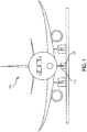
- An aircraft 100 in accordance with various embodiments is illustrated.
- An aircraft 100 may be any type of aircraft 100 comprising at least a landing gear system 110 including an aircraft wheel assembly 120.
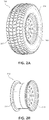
- an aircraft wheel 220 may comprise an inboard wheel portion 230 and an outboard wheel portion 240.
- inboard and outboard are meant to refer to positions along the axis of rotation of the aircraft wheel.
- the term “inboard” may refer to a position along the axis of rotation of an aircraft wheel that is closer to the longitudinal centerline of an aircraft and the term “outboard” means a position along the axis of rotation of the aircraft wheel that is further from the longitudinal centerline of an aircraft.
- Aircraft wheel 220 may be configured to be operatively coupled to a tire 250.
- tire 250 may be mounted on aircraft wheel 220.
- Tire 250 may define a pressurizable chamber between tire 250 and aircraft wheel 220.
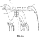
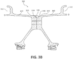
- an inboard wheel portion 330 may be configured to provide structural support to an aircraft wheel assembly.
- Inboard wheel portion 330 may comprise an inboard rim 332 located opposite of an inboard tubewell 334.
- Inboard rim 332 may be configured to operatively and/or removably couple to a tire.
- Inboard tubewell 334 may comprise an inboard mating surface 336 on an axially outer edge of the inboard tubewell 334, opposite of an inboard tubewell radius 335.
- the inboard mating surface 336 of the inboard tubewell 334 may be configured to removably couple to an outboard mating surface 346 of an outboard tubewell 344 of an outboard wheel portion 340.
- inboard wheel portion 330 may be any shape suitable for providing structure and support to an aircraft wheel assembly, such as, cylindrically shaped.
- Inboard wheel portion 330 may be made of any suitable material.
- inboard wheel portion 330 may be made from a substantially rigid and durable metal.
- Inboard wheel portion 330 may also be made from any suitably rigid and sufficiently durable material such as, for example, a plastic, an alloy, a composite, a polymer, and/or any other suitable material.
- an outboard wheel portion 340 may be configured to provide structural support to an aircraft wheel assembly.
- Outboard wheel portion 340 may comprise an outboard rim 342 located opposite of an outboard tubewell 344.
- Outboard rim 342 may be configured to be operatively and/or removably coupled to a tire.
- Outboard tubewell 344 may comprise an outboard mating surface 346 on an axially outer edge of the outboard tubewell 344.
- Outboard mating surface 346 may operatively and/or removably couple to inboard mating surface 336.
- outboard mating surface 346 may operatively and/or removably couple to inboard mating surface 336 by any suitable method and means.
- outboard mating surface 346 may be coupled to inboard mating surface 336 using fastener bolts.
- Outboard mating surface 346 may also be coupled to inboard mating surface 336 using a lock-ring design, and/or any other suitable method.
- outboard wheel portion 340 may be any shape suitable for providing structure and support to an aircraft wheel assembly, such as, cylindrically shaped.
- Outboard wheel portion 340 may be made of any suitable material.
- outboard wheel portion 340 may be made from a substantially rigid and durable metal.
- Outboard wheel portion 340 may also be made from any suitably rigid and sufficiently durable material such as, for example, a plastic, an alloy, a composite, a polymer, and/or any other suitable material.
- an inboard O-ring groove 438 may be configured to provide structural support for an O-ring 470.
- An aircraft wheel assembly in various embodiments, may also comprise multiple inboard O-ring grooves configured to provide structural support to multiple O-rings.
- Inboard O-ring groove 438 may be formed into a recess extending axially inward on an outer edge of inboard mating surface 436.
- Inboard O-ring groove designs of the prior art typically comprise an O-ring groove having a simple circular radius. This simple circular radius results in a small radius in the recess of the inboard O-ring groove, causing an unwanted high stress gradient in the groove.
- the recess of inboard O-ring groove 438 may be formed into any suitable shape resulting in a larger radius to inboard O-ring groove 438, such as, for example, a partially oval shape.
- forming the inboard O-ring groove 438 into a partially oval-shaped recess may have the desired effect of decreasing the stress gradient in the area.
- an outboard register 448 may be configured to provide structural support for an O-ring 470.
- An aircraft wheel assembly in various embodiments, may comprise multiple outboard registers, configured to provide structural support to multiple O-rings.
- Outboard register 448 may be located on an outer edge of outboard mating surface 446.
- Outboard register 448 may be any shape suitable to provide structural support for an O-ring 470.
- Outboard register 448 may be configured to align with inboard O-ring groove 438 when the outboard wheel portion 440 is coupled to the inboard wheel portion 430. In this regard, outboard register 448 and inboard O-ring groove 438 may substantially align together to form a single resulting groove configured to fit an O-ring 470.
- Outboard register 448 designs in the prior art typically are shaped substantially flat.
- a substantially flat outboard register provides no ability to move inboard O-ring groove 438 axially away from inboard tubewell radius 435.
- a greater thickness 460 between inboard O-ring groove 438 and inboard tubewell radius 435 decreases the resulting stress gradient in the inboard O-ring groove 438.
- outboard register 448 may be formed into any suitable recess resulting in an enhanced thickness 460 between inboard O-ring groove 438 and inboard tubewell radius 435.
- outboard register 448 may be formed into a recess protruding axially beyond outboard mating surface 446.
- increasing the thickness 460 between inboard O-ring groove 438 and inboard tubewell radius 435 may be accomplished by forming the recess of the outboard register 448 into a partially oval shape.
- inboard O-ring groove 438 The depth of the recess in outboard register 448 would then allow inboard O-ring groove 438 to be formed closer to the outer edge of inboard mating surface 436, and at a further distance axially away from inboard tubewell radius 435. Because inboard O-ring groove 438 would be closer to the outer edge of inboard mating surface 436, thickness 460 between inboard O-ring groove 438 and inboard tubewell radius 435 would be enhanced.
- the radius of the recessed outboard register 448 may be in a 1:1 ratio to the radius of the inboard O-ring groove 438.
- an O-ring 470 may be configured to seal the aircraft wheel assembly when outboard wheel portion 440 is coupled to inboard wheel portion 430.
- O-ring 470 may be located between inboard O-ring groove 438 and outboard register 448 when outboard wheel portion 440 is coupled to inboard wheel portion 430.
- an O-ring 470 may be located between each separately aligned inboard O-ring groove and outboard register.
- O-ring 470 may be any shape suitable for sealing an aircraft wheel assembly 420.
- O-ring 470 may have a substantially circular shape.
- O-ring 470 may also be cylindrically shaped, or have a rectangular shape.
- O-ring 470 may be made of any suitable material and may have any suitable coating.
- O-ring 470 may be made from any flexible and durable rubber material.
- O-ring 470 may also be made from any suitably elastic and durable material such as, for example, polytetrafluoroethylene (PTFE), ethylene propylene diene monomer (EPDM) rubber, nitrile (Buna-N) rubber, neoprene, Viton fluorocarbon, and/or any other suitable material.
- PTFE polytetrafluoroethylene
- EPDM ethylene propylene diene monomer
- Buna-N nitrile
- neoprene Viton fluorocarbon
- any other suitable material such as, for example, polytetraflu
- references to "various embodiments”, “one embodiment”, “an embodiment”, “an example embodiment”, etc. indicate that the embodiment described may include a particular feature, structure, or characteristic, but every embodiment may not necessarily include the particular feature, structure, or characteristic. Moreover, such phrases are not necessarily referring to the same embodiment. Further, when a particular feature, structure, or characteristic is described in connection with an embodiment, it is submitted that it is within the knowledge of one skilled in the art to affect such feature, structure, or characteristic in connection with other embodiments whether or not explicitly described. After reading the description, it will be apparent to one skilled in the relevant art(s) how to implement the disclosure in alternative embodiments.
Landscapes
- Engineering & Computer Science (AREA)
- Mechanical Engineering (AREA)
- Aviation & Aerospace Engineering (AREA)
- Gasket Seals (AREA)
Abstract
Description
- The present disclosure relates to aircraft wheels, and more specifically, to an oval O-ring groove for an aircraft wheel.
- O-ring grooves may experience fatigue in aircraft wheels. Current O-ring groove designs can create high-stress gradients due to the size of the groove radius, depth of the groove and the proximity to bolted joints, as well as the load path from the wheel tubewell through tie bolts. This resulting high-stress gradient can lead to unpredictable fatigue life at the O-ring groove.
- In various embodiments, a wheel for an aircraft may comprise an inboard wheel portion and an inboard O-ring groove. The inboard wheel portion may include an inboard rim located opposite of an inboard tubewell. The inboard tubewell may have an inboard mating surface located on an axially outer edge of the inboard tubewell. The inboard O-ring groove may be formed as a partial oval-shaped recess located on an outer edge of the inboard mating surface.
- In various embodiments, an aircraft wheel may comprise an inboard wheel portion, an at least one inboard O-ring groove, an outboard wheel portion, and an at least one outboard register. The inboard wheel portion may include an inboard rim located opposite of an inboard tubewell. The inboard tubewell may have an inboard mating surface located on an axially outer edge of the inboard tubewell. The at least one inboard O-ring groove may be formed as a recess located on an outer edge of the inboard mating surface. The outboard wheel portion may include an outboard rim located opposite of an outboard tubewell. The outboard tubewell may have an outboard mating surface located on an axially outer edge of the outboard tubewell. The outboard mating surface may be configured to removably couple to the inboard mating surface. The at least one outboard register may be formed as a recess extending axially inward on an outer edge of the outboard mating surface.
- In various embodiments, a wheel assembly may comprise an inboard wheel portion, an inboard O-ring groove, an outboard wheel portion, and an outboard register. The inboard wheel portion may include an inboard rim located opposite of an inboard tubewell. The inboard tubewell may have an inboard mating surface located on an axially outer edge of the inboard tubewell. The inboard O-ring groove may be formed as a partial oval-shaped recess located on an outer edge of the inboard mating surface. The outboard wheel portion may include an outboard rim located opposite of an outboard tubewell. The outboard tubewell may have an outboard mating surface located on an axially outer edge of the outboard tubewell. The outboard mating surface may be configured to removably couple to the inboard mating surface. The outboard register may be formed as a partial recess extending axially inward on an outer edge of the outboard mating surface, wherein a valley of the recess of the outboard register is flat.
- The forgoing features and elements may be combined in various combinations without exclusivity, unless expressly indicated herein otherwise. These features and elements as well as the operation of the disclosed embodiments will become more apparent in light of the following description and accompanying drawings.
- The subject matter of the present disclosure is particularly pointed out and distinctly claimed in the concluding portion of the specification. A more complete understanding of the present disclosure, however, may best be obtained by referring to the detailed description and claims when considered in connection with the following illustrative figures. In the following figures, like reference numbers refer to similar elements and steps throughout the figures.
-
FIG. 1 illustrates a front view of an aircraft, in accordance with various embodiments; -
FIG. 2A illustrates a side perspective view of a wheel assembly with a tire, in accordance with various embodiments; -
FIG. 2B illustrates a side perspective view of a wheel assembly without a tire, in accordance with various embodiments; -
FIG. 3A illustrates a perspective cross-sectional view of a wheel assembly, in accordance with various embodiments; -
FIG. 3B illustrates a side cross-sectional view of a wheel assembly, in accordance with various embodiments; -
FIG. 4A illustrates an exploded cross-sectional view of an inboard wheel portion coupled to an outboard wheel portion in a wheel assembly, in accordance with various embodiments; and -
FIG. 4B illustrates a cross sectional view of an inboard wheel portion coupled to an outboard wheel portion in a wheel assembly, in accordance with various embodiments. - Elements and steps in the figures are illustrated for simplicity and clarity and have not necessarily been rendered according to any particular sequence. For example, steps that may be performed concurrently or in different order are illustrated in the figures to help to improve understanding of embodiments of the present disclosure.
- The detailed description of exemplary embodiments herein makes reference to the accompanying drawings, which show exemplary embodiments by way of illustration. While these exemplary embodiments are described in sufficient detail to enable those skilled in the art to practice the disclosures, it should be understood that other embodiments may be realized and that logical changes and adaptations in design and construction may be made in accordance with this disclosure and the teachings herein. Thus, the detailed description herein is presented for purposes of illustration only and not of limitation.
- The scope of the disclosure is defined by the appended claims and their legal equivalents rather than by merely the examples described. For example, the steps recited in any of the method or process descriptions may be executed in any order and are not necessarily limited to the order presented. Furthermore, any reference to singular includes plural embodiments, and any reference to more than one component or step may include a singular embodiment or step. Also, any reference to attached, fixed, connected or the like may include permanent, removable, temporary, partial, full and/or any other possible attachment option. Additionally, any reference to without contact (or similar phrases) may also include reduced contact or minimal contact. Surface shading lines may be used throughout the figures to denote different parts but not necessarily to denote the same or different materials.
- Aircraft wheels are an important component of an aircraft landing system. With tires mounted on the wheels, the aircraft wheels support the entire weight of an aircraft during takeoff and landing. Typical modem aircraft wheels are comprised of two pieces: an inboard wheel portion and an outboard wheel portion. These two wheel portions are generally held together, such as, for example, by a bolt, and the two wheel portions contain an O-ring groove and/or register at the mating surface of each wheel portion for an O-ring. The O-ring is designed to form an air-tight seal to the aircraft wheel when the inboard wheel portion is coupled to the outboard wheel portion. Because of the amount of weight and stress on the wheel caused by the aircraft, the O-ring groove may experience fatigue.
- The present disclosure describes various embodiments of O-ring grooves for use with an aircraft wheel, aircraft wheels, as well as an aircraft wheel assembly. Various embodiments of such systems may be utilized in new aircraft designs, or retrofit to existing aircrafts. As will be described in more detail, systems and apparatuses comprising O-ring grooves are provided herein.
- With initial reference to
FIG. 1 , anaircraft 100 in accordance with various embodiments is illustrated. Anaircraft 100 may be any type ofaircraft 100 comprising at least alanding gear system 110 including anaircraft wheel assembly 120. - In various embodiments and with reference to
FIGs. 2A and 2B , anaircraft wheel 220 may comprise aninboard wheel portion 230 and anoutboard wheel portion 240. As used herein, "inboard" and "outboard" are meant to refer to positions along the axis of rotation of the aircraft wheel. For example, in various embodiments, the term "inboard" may refer to a position along the axis of rotation of an aircraft wheel that is closer to the longitudinal centerline of an aircraft and the term "outboard" means a position along the axis of rotation of the aircraft wheel that is further from the longitudinal centerline of an aircraft. However, it should be understood generally that the term "inboard" may refer to a component that occupies a position along the axis of rotation of an aircraft wheel that is axially displaced from another component. In that regard, in various embodiments, the aircraft wheel portions disclosed herein may take on configurations that have mirror image symmetry with the embodiments shown in the Figures.Aircraft wheel 220 may be configured to be operatively coupled to atire 250. In this regard,tire 250 may be mounted onaircraft wheel 220.Tire 250 may define a pressurizable chamber betweentire 250 andaircraft wheel 220. - In various embodiments, and with reference to
FIGs. 3A and3B , aninboard wheel portion 330 may be configured to provide structural support to an aircraft wheel assembly.Inboard wheel portion 330 may comprise aninboard rim 332 located opposite of aninboard tubewell 334.Inboard rim 332 may be configured to operatively and/or removably couple to a tire.Inboard tubewell 334 may comprise aninboard mating surface 336 on an axially outer edge of theinboard tubewell 334, opposite of aninboard tubewell radius 335. Theinboard mating surface 336 of theinboard tubewell 334 may be configured to removably couple to anoutboard mating surface 346 of anoutboard tubewell 344 of anoutboard wheel portion 340. - In various embodiments,
inboard wheel portion 330 may be any shape suitable for providing structure and support to an aircraft wheel assembly, such as, cylindrically shaped.Inboard wheel portion 330 may be made of any suitable material. For example,inboard wheel portion 330 may be made from a substantially rigid and durable metal.Inboard wheel portion 330 may also be made from any suitably rigid and sufficiently durable material such as, for example, a plastic, an alloy, a composite, a polymer, and/or any other suitable material. - In various embodiments an
outboard wheel portion 340 may be configured to provide structural support to an aircraft wheel assembly.Outboard wheel portion 340 may comprise anoutboard rim 342 located opposite of anoutboard tubewell 344.Outboard rim 342 may be configured to be operatively and/or removably coupled to a tire.Outboard tubewell 344 may comprise anoutboard mating surface 346 on an axially outer edge of theoutboard tubewell 344.Outboard mating surface 346 may operatively and/or removably couple toinboard mating surface 336. In this regard,outboard mating surface 346 may operatively and/or removably couple toinboard mating surface 336 by any suitable method and means. For example,outboard mating surface 346 may be coupled toinboard mating surface 336 using fastener bolts.Outboard mating surface 346 may also be coupled toinboard mating surface 336 using a lock-ring design, and/or any other suitable method. - In various embodiments,
outboard wheel portion 340 may be any shape suitable for providing structure and support to an aircraft wheel assembly, such as, cylindrically shaped.Outboard wheel portion 340 may be made of any suitable material. For example,outboard wheel portion 340 may be made from a substantially rigid and durable metal.Outboard wheel portion 340 may also be made from any suitably rigid and sufficiently durable material such as, for example, a plastic, an alloy, a composite, a polymer, and/or any other suitable material. - In various embodiments, and with reference to
FIGs. 4A and 4B , an inboard O-ring groove 438 may be configured to provide structural support for an O-ring 470. An aircraft wheel assembly, in various embodiments, may also comprise multiple inboard O-ring grooves configured to provide structural support to multiple O-rings. Inboard O-ring groove 438 may be formed into a recess extending axially inward on an outer edge ofinboard mating surface 436. - Inboard O-ring groove designs of the prior art typically comprise an O-ring groove having a simple circular radius. This simple circular radius results in a small radius in the recess of the inboard O-ring groove, causing an unwanted high stress gradient in the groove. In various embodiments, it may be desirable to decrease the stress gradient by increasing the radius of the inboard O-
ring groove 438. The recess of inboard O-ring groove 438 may be formed into any suitable shape resulting in a larger radius to inboard O-ring groove 438, such as, for example, a partially oval shape. In this regard, forming the inboard O-ring groove 438 into a partially oval-shaped recess may have the desired effect of decreasing the stress gradient in the area. - In various embodiments, and with further reference to
FIGs. 4A and 4B , anoutboard register 448 may be configured to provide structural support for an O-ring 470. An aircraft wheel assembly, in various embodiments, may comprise multiple outboard registers, configured to provide structural support to multiple O-rings.Outboard register 448 may be located on an outer edge ofoutboard mating surface 446.Outboard register 448 may be any shape suitable to provide structural support for an O-ring 470.Outboard register 448 may be configured to align with inboard O-ring groove 438 when theoutboard wheel portion 440 is coupled to theinboard wheel portion 430. In this regard,outboard register 448 and inboard O-ring groove 438 may substantially align together to form a single resulting groove configured to fit an O-ring 470. -
Outboard register 448 designs in the prior art typically are shaped substantially flat. A substantially flat outboard register provides no ability to move inboard O-ring groove 438 axially away frominboard tubewell radius 435. In various embodiments, it may be desirable to increase thethickness 460 between inboard O-ring groove 438 andinboard tubewell radius 435 when theoutboard wheel portion 440 is coupled to theinboard wheel portion 430, by moving inboard O-ring groove 438 axially away frominboard tubewell radius 435. In this regard, agreater thickness 460 between inboard O-ring groove 438 andinboard tubewell radius 435 decreases the resulting stress gradient in the inboard O-ring groove 438. - In various embodiments,
outboard register 448 may be formed into any suitable recess resulting in anenhanced thickness 460 between inboard O-ring groove 438 andinboard tubewell radius 435. In this regard,outboard register 448 may be formed into a recess protruding axially beyondoutboard mating surface 446. As an example, in various embodiments whereoutboard register 448 is aligned with inboard O-ring groove 438, such as whenoutboard wheel portion 440 is coupled toinboard wheel portion 430, increasing thethickness 460 between inboard O-ring groove 438 andinboard tubewell radius 435 may be accomplished by forming the recess of theoutboard register 448 into a partially oval shape. The depth of the recess inoutboard register 448 would then allow inboard O-ring groove 438 to be formed closer to the outer edge ofinboard mating surface 436, and at a further distance axially away frominboard tubewell radius 435. Because inboard O-ring groove 438 would be closer to the outer edge ofinboard mating surface 436,thickness 460 between inboard O-ring groove 438 andinboard tubewell radius 435 would be enhanced. In various embodiments, the radius of the recessedoutboard register 448 may be in a 1:1 ratio to the radius of the inboard O-ring groove 438. - In various embodiments, and with further reference to
FIGs. 4A and 4B , an O-ring 470 may be configured to seal the aircraft wheel assembly whenoutboard wheel portion 440 is coupled toinboard wheel portion 430. O-ring 470 may be located between inboard O-ring groove 438 andoutboard register 448 whenoutboard wheel portion 440 is coupled toinboard wheel portion 430. In various embodiments having multiple inboard O-ring grooves and multiple outboard registers, an O-ring 470 may be located between each separately aligned inboard O-ring groove and outboard register. - In various embodiments, O-
ring 470 may be any shape suitable for sealing anaircraft wheel assembly 420. In this regard, O-ring 470 may have a substantially circular shape. O-ring 470 may also be cylindrically shaped, or have a rectangular shape. O-ring 470 may be made of any suitable material and may have any suitable coating. For example, O-ring 470 may be made from any flexible and durable rubber material. O-ring 470 may also be made from any suitably elastic and durable material such as, for example, polytetrafluoroethylene (PTFE), ethylene propylene diene monomer (EPDM) rubber, nitrile (Buna-N) rubber, neoprene, Viton fluorocarbon, and/or any other suitable material. - Benefits, other advantages, and solutions to problems have been described herein with regard to specific embodiments. Furthermore, the connecting lines shown in the various figures contained herein are intended to represent exemplary functional relationships and/or physical couplings between the various elements. It should be noted that many alternative or additional functional relationships or physical connections may be present in a practical system. However, the benefits, advantages, solutions to problems, and any elements that may cause any benefit, advantage, or solution to occur or become more pronounced are not to be construed as critical, required, or essential features or elements of the disclosures. The scope of the disclosures is accordingly to be limited by nothing other than the appended claims and their legal equivalents, in which reference to an element in the singular is not intended to mean "one and only one" unless explicitly so stated, but rather "one or more." Moreover, where a phrase similar to "at least one of A, B, or C" is used in the claims, it is intended that the phrase be interpreted to mean that A alone may be present in an embodiment, B alone may be present in an embodiment, C alone may be present in an embodiment, or that any combination of the elements A, B and C may be present in a single embodiment; for example, A and B, A and C, B and C, or A and B and C.
- Systems, methods and apparatus are provided herein. In the detailed description herein, references to "various embodiments", "one embodiment", "an embodiment", "an example embodiment", etc., indicate that the embodiment described may include a particular feature, structure, or characteristic, but every embodiment may not necessarily include the particular feature, structure, or characteristic. Moreover, such phrases are not necessarily referring to the same embodiment. Further, when a particular feature, structure, or characteristic is described in connection with an embodiment, it is submitted that it is within the knowledge of one skilled in the art to affect such feature, structure, or characteristic in connection with other embodiments whether or not explicitly described. After reading the description, it will be apparent to one skilled in the relevant art(s) how to implement the disclosure in alternative embodiments.
Claims (15)
- A wheel (220) for an aircraft, comprising:an inboard wheel portion (230; 330; 430) having an inboard rim (332) located opposite of an inboard tubewell (334), the inboard tubewell (334) having an inboard mating surface (336; 436) on the inboard tubewell (334); andan inboard O-ring groove (438) located on an outer edge of the inboard mating surface (336; 436), wherein the inboard O-ring groove (438) is formed as a partial oval-shaped recess.
- The wheel of claim 1, further comprising an outboard wheel portion (240; 340; 440) having an outer rim (342) located opposite of an outboard tubewell (344), the outboard tubewell (344) having an outboard mating surface (346; 446) on the outboard tubewell (344), wherein the outboard mating surface (346; 446) is configured to removably couple to the inboard mating surface (336; 436).
- The wheel of claim 2, further comprising an outboard register (448) on an outer edge of the outboard mating surface (346; 446), wherein the outboard register (448) is configured to align with the inboard O-ring groove (438) when the outboard wheel portion (240; 340; 440) is coupled to the inboard wheel portion (230; 330; 430).
- The wheel of claim 3, further comprising an O-ring (470) located between the inboard O-ring groove (438) and the outboard register (448).
- The wheel of clam 3 or 4, wherein the outboard register (448) is formed as a recess protruding axially beyond the outboard mating surface (346; 446).
- The wheel of claim 5, wherein a radius of the partial oval-shaped recess of the inboard O-ring groove (438) is in a 1:1 ratio to a radius of the recess of the outboard register (448).
- The wheel of claim 5 or 6, wherein the recess of the outboard register (448) is formed in a partially oval shape.
- An aircraft wheel (220), comprising:an inboard wheel portion (230; 330; 430) having an inboard rim (332) located opposite of an inboard tubewell (334), the inboard tubewell (334) having an inboard mating surface (336; 436) on the inboard tubewell (334);an at least one inboard O-ring groove (438) formed as a recess located on an outer edge of the inboard mating surface (336; 436);an outboard wheel portion (240; 340; 440) having an outboard rim (342) located opposite of an outboard tubewell (344), the outboard tubewell (344) having an outboard mating surface (346; 446) on the outboard tubewell (344), wherein the outboard mating surface (346; 446) is configured to removably couple to the inboard mating surface (336; 436); andan at least one outboard register (448) formed as a partial recess protruding axially beyond the outboard mating surface (346; 446).
- The aircraft wheel of claim 8, wherein the at least one inboard O-ring groove (438) and the at least one outboard register (448) substantially align when the inboard mating surface (336; 436) is coupled to the outboard mating surface (346; 446).
- The aircraft wheel of claim 8 or 9, further comprising an at least one O-ring (470) located between the at least one inboard O-ring groove (438) and the at least one outboard register (448).
- The aircraft wheel of claim 8, 9 or 10, wherein the recess of the at least one outboard register (448) is partially oval-shaped.
- The aircraft wheel of any of claims 8 to 11, wherein the recess of the at least one inboard O-ring groove (438) is partially oval-shaped.
- The aircraft wheel of any of claims 8 to 12, wherein a radius of the recess of the at least one inboard O-ring groove (438) is in a 1:1 ratio to a radius of the recess of the at least one outboard register (448).
- A wheel assembly (420), comprising:an inboard wheel portion (230; 330; 430) having an outer rim (342) located opposite of an inboard tubewell (334), the inboard tubewell (334) having an inboard mating surface (336; 436) on the inboard tubewell (334);an inboard O-ring groove (348) located on an outer edge of the inboard mating surface (336; 436), wherein the inboard O-ring groove (348) is formed as a partial oval-shaped recess;an outboard wheel portion (240; 340; 440) having an outer rim (342) located opposite of an outboard tubewell (344), the outboard tubewell (344) having an outboard mating surface (346; 446) on the outboard tubewell (344), wherein the outboard mating surface (346; 446) is configured to removably couple to the inboard mating surface (336; 436); andan outboard register (448) formed as a partial recess protruding axially beyond the outboard mating surface (346; 446), wherein a valley of the recess of the outboard register (448) is flat.
- The wheel assembly of claim 14, wherein the inboard O-ring groove (438) and the outboard register (448) align when the inboard mating surface (336; 436) is removably coupled to the outboard mating surface (346; 446), and, optionally, further comprising an O-ring (470) located between the inboard O-ring groove (438) and the outboard register (448).
Priority Applications (1)
| Application Number | Priority Date | Filing Date | Title |
|---|---|---|---|
| EP19166488.7A EP3543117B1 (en) | 2015-11-12 | 2016-11-10 | Aircraft wheel |
Applications Claiming Priority (1)
| Application Number | Priority Date | Filing Date | Title |
|---|---|---|---|
| US14/939,340 US10144245B2 (en) | 2015-11-12 | 2015-11-12 | Oval O-ring groove for aircraft wheels |
Related Child Applications (1)
| Application Number | Title | Priority Date | Filing Date |
|---|---|---|---|
| EP19166488.7A Division EP3543117B1 (en) | 2015-11-12 | 2016-11-10 | Aircraft wheel |
Publications (2)
| Publication Number | Publication Date |
|---|---|
| EP3168144A1 true EP3168144A1 (en) | 2017-05-17 |
| EP3168144B1 EP3168144B1 (en) | 2019-05-01 |
Family
ID=57286323
Family Applications (2)
| Application Number | Title | Priority Date | Filing Date |
|---|---|---|---|
| EP19166488.7A Active EP3543117B1 (en) | 2015-11-12 | 2016-11-10 | Aircraft wheel |
| EP16198191.5A Active EP3168144B1 (en) | 2015-11-12 | 2016-11-10 | Aircraft wheel with oval o-ring groove |
Family Applications Before (1)
| Application Number | Title | Priority Date | Filing Date |
|---|---|---|---|
| EP19166488.7A Active EP3543117B1 (en) | 2015-11-12 | 2016-11-10 | Aircraft wheel |
Country Status (2)
| Country | Link |
|---|---|
| US (1) | US10144245B2 (en) |
| EP (2) | EP3543117B1 (en) |
Families Citing this family (2)
| Publication number | Priority date | Publication date | Assignee | Title |
|---|---|---|---|---|
| CN107757249A (en) * | 2017-11-21 | 2018-03-06 | 西安航空制动科技有限公司 | A kind of encapsulated snap ring and preparation method thereof |
| FR3110492B1 (en) * | 2020-05-20 | 2022-08-05 | Sodijantes Ind | Adaptable rim wheel, assembly, motor vehicle and associated adaptation method |
Citations (7)
| Publication number | Priority date | Publication date | Assignee | Title |
|---|---|---|---|---|
| US3044154A (en) * | 1956-11-23 | 1962-07-17 | Bendix Corp | Process of making forged wheel constructions |
| US3201174A (en) * | 1959-06-22 | 1965-08-17 | Bendix Corp | Safety device for aircraft wheels |
| US20030140998A1 (en) * | 2002-01-28 | 2003-07-31 | Kentaro Oba | Multi-piece rim |
| US20050236081A1 (en) * | 2004-04-27 | 2005-10-27 | Olivier Marsaly | Automotive wheel with a retaining sealing groove |
| US20060037685A1 (en) * | 2004-08-23 | 2006-02-23 | Alcoa Inc. | Multi-piece aluminum wheel and associated method |
| EP2743096A1 (en) * | 2012-12-12 | 2014-06-18 | Goodrich Corporation | Threaded side rim or threaded lock ring wheel for use with low-pressure or non-pneumatic tires |
| US20150273938A1 (en) * | 2014-03-28 | 2015-10-01 | Messier-Bugatti-Dowty | Aircraft wheel comprising a duct establishing a leakage path in the wheel |
Family Cites Families (11)
| Publication number | Priority date | Publication date | Assignee | Title |
|---|---|---|---|---|
| US5855257A (en) | 1996-12-09 | 1999-01-05 | Chrysler Corporation | Damper for brake noise reduction |
| US20040070260A1 (en) * | 2000-08-11 | 2004-04-15 | Chung Thiam Eng | Wheel hub assemblies |
| US7051845B2 (en) | 2001-10-10 | 2006-05-30 | Goodrich Corporation | Heat shield assembly for aircraft wheel and brake assembly |
| US8020943B2 (en) | 2005-09-29 | 2011-09-20 | Goodrich Corporation | Aircraft wheel assembly |
| US7523816B2 (en) | 2006-03-06 | 2009-04-28 | Honeywell International Inc. | Method and brake assembly retention device with automatic operation |
| SI2397719T1 (en) | 2010-06-16 | 2013-10-30 | Brembo Sgl Carbon Ceramic Brakes Gmbh | Brake pads for improved wet braking performance |
| US20120091666A1 (en) | 2010-10-18 | 2012-04-19 | Akebono Corporation | Brake caliper seal groove |
| US20120248855A1 (en) | 2011-04-04 | 2012-10-04 | Honeywell International Inc. | Anti-rotation interlocking inboard and outboard wheel components |
| FR2999982B1 (en) * | 2012-12-20 | 2015-02-20 | Messier Bugatti Dowty | AIRCRAFT WHEEL EQUIPPED WITH BOLTS-BARRETTES. |
| US9346318B2 (en) * | 2013-03-27 | 2016-05-24 | Goodrich Corporation | System and method for a wheel lock ring assembly |
| US9091313B2 (en) | 2013-08-27 | 2015-07-28 | Akebono Brake Corporation | Full contact brake |
-
2015
- 2015-11-12 US US14/939,340 patent/US10144245B2/en active Active
-
2016
- 2016-11-10 EP EP19166488.7A patent/EP3543117B1/en active Active
- 2016-11-10 EP EP16198191.5A patent/EP3168144B1/en active Active
Patent Citations (7)
| Publication number | Priority date | Publication date | Assignee | Title |
|---|---|---|---|---|
| US3044154A (en) * | 1956-11-23 | 1962-07-17 | Bendix Corp | Process of making forged wheel constructions |
| US3201174A (en) * | 1959-06-22 | 1965-08-17 | Bendix Corp | Safety device for aircraft wheels |
| US20030140998A1 (en) * | 2002-01-28 | 2003-07-31 | Kentaro Oba | Multi-piece rim |
| US20050236081A1 (en) * | 2004-04-27 | 2005-10-27 | Olivier Marsaly | Automotive wheel with a retaining sealing groove |
| US20060037685A1 (en) * | 2004-08-23 | 2006-02-23 | Alcoa Inc. | Multi-piece aluminum wheel and associated method |
| EP2743096A1 (en) * | 2012-12-12 | 2014-06-18 | Goodrich Corporation | Threaded side rim or threaded lock ring wheel for use with low-pressure or non-pneumatic tires |
| US20150273938A1 (en) * | 2014-03-28 | 2015-10-01 | Messier-Bugatti-Dowty | Aircraft wheel comprising a duct establishing a leakage path in the wheel |
Also Published As
| Publication number | Publication date |
|---|---|
| EP3543117B1 (en) | 2021-09-15 |
| EP3168144B1 (en) | 2019-05-01 |
| US20170136812A1 (en) | 2017-05-18 |
| EP3543117A1 (en) | 2019-09-25 |
| US10144245B2 (en) | 2018-12-04 |
Similar Documents
| Publication | Publication Date | Title |
|---|---|---|
| EP3156254B1 (en) | Short trapezoidal wheel gasket | |
| EP3162592A1 (en) | Airless tire | |
| EP3168144B1 (en) | Aircraft wheel with oval o-ring groove | |
| EP2799245B1 (en) | System and method for a wheel lock ring assembly | |
| US10604246B2 (en) | Rotorcraft rotor assemblies | |
| EP2133218A3 (en) | Radial aircraft tire | |
| EP3452308B1 (en) | Adapter for a wheeled assembly and a wheeled assembly comprising same | |
| EP3159179B1 (en) | Mismatch side rim and lock ring interface angles for lock ring wheel | |
| EP3306118B1 (en) | Hybrid metallic/composite joint with enhanced performance | |
| US10486799B2 (en) | Rod end | |
| EP3084247B1 (en) | Winged elastomeric coupling and clamp ring | |
| CN205344362U (en) | Aircraft wheel subassembly | |
| US10689073B2 (en) | Apparatus and system for marine propeller blade dovetail stress reduction | |
| KR20150100016A (en) | Hubless propeller | |
| EP3081389B1 (en) | Safety deflation wheel seal design | |
| US9499257B2 (en) | Weight reducing landing gear features | |
| EP3090943A1 (en) | Landing gear including a bogie beam assembly and method for coupling an axle to a bogie beam thereof | |
| US10005548B2 (en) | Compliant lower bearing with tapered outer diameter | |
| CN107000485B (en) | Protective crown reinforcement for aircraft tyre | |
| CN105150764A (en) | Airplane wheel assembly |
Legal Events
| Date | Code | Title | Description |
|---|---|---|---|
| PUAI | Public reference made under article 153(3) epc to a published international application that has entered the european phase |
Free format text: ORIGINAL CODE: 0009012 |
|
| STAA | Information on the status of an ep patent application or granted ep patent |
Free format text: STATUS: THE APPLICATION HAS BEEN PUBLISHED |
|
| AK | Designated contracting states |
Kind code of ref document: A1 Designated state(s): AL AT BE BG CH CY CZ DE DK EE ES FI FR GB GR HR HU IE IS IT LI LT LU LV MC MK MT NL NO PL PT RO RS SE SI SK SM TR |
|
| AX | Request for extension of the european patent |
Extension state: BA ME |
|
| STAA | Information on the status of an ep patent application or granted ep patent |
Free format text: STATUS: REQUEST FOR EXAMINATION WAS MADE |
|
| 17P | Request for examination filed |
Effective date: 20171117 |
|
| RBV | Designated contracting states (corrected) |
Designated state(s): AL AT BE BG CH CY CZ DE DK EE ES FI FR GB GR HR HU IE IS IT LI LT LU LV MC MK MT NL NO PL PT RO RS SE SI SK SM TR |
|
| STAA | Information on the status of an ep patent application or granted ep patent |
Free format text: STATUS: EXAMINATION IS IN PROGRESS |
|
| 17Q | First examination report despatched |
Effective date: 20180308 |
|
| GRAP | Despatch of communication of intention to grant a patent |
Free format text: ORIGINAL CODE: EPIDOSNIGR1 |
|
| STAA | Information on the status of an ep patent application or granted ep patent |
Free format text: STATUS: GRANT OF PATENT IS INTENDED |
|
| INTG | Intention to grant announced |
Effective date: 20181109 |
|
| GRAS | Grant fee paid |
Free format text: ORIGINAL CODE: EPIDOSNIGR3 |
|
| GRAA | (expected) grant |
Free format text: ORIGINAL CODE: 0009210 |
|
| STAA | Information on the status of an ep patent application or granted ep patent |
Free format text: STATUS: THE PATENT HAS BEEN GRANTED |
|
| AK | Designated contracting states |
Kind code of ref document: B1 Designated state(s): AL AT BE BG CH CY CZ DE DK EE ES FI FR GB GR HR HU IE IS IT LI LT LU LV MC MK MT NL NO PL PT RO RS SE SI SK SM TR |
|
| REG | Reference to a national code |
Ref country code: GB Ref legal event code: FG4D |
|
| REG | Reference to a national code |
Ref country code: CH Ref legal event code: EP Ref country code: AT Ref legal event code: REF Ref document number: 1126588 Country of ref document: AT Kind code of ref document: T Effective date: 20190515 |
|
| REG | Reference to a national code |
Ref country code: DE Ref legal event code: R096 Ref document number: 602016013121 Country of ref document: DE |
|
| REG | Reference to a national code |
Ref country code: IE Ref legal event code: FG4D |
|
| REG | Reference to a national code |
Ref country code: NL Ref legal event code: MP Effective date: 20190501 |
|
| REG | Reference to a national code |
Ref country code: LT Ref legal event code: MG4D |
|
| PG25 | Lapsed in a contracting state [announced via postgrant information from national office to epo] |
Ref country code: LT Free format text: LAPSE BECAUSE OF FAILURE TO SUBMIT A TRANSLATION OF THE DESCRIPTION OR TO PAY THE FEE WITHIN THE PRESCRIBED TIME-LIMIT Effective date: 20190501 Ref country code: HR Free format text: LAPSE BECAUSE OF FAILURE TO SUBMIT A TRANSLATION OF THE DESCRIPTION OR TO PAY THE FEE WITHIN THE PRESCRIBED TIME-LIMIT Effective date: 20190501 Ref country code: NL Free format text: LAPSE BECAUSE OF FAILURE TO SUBMIT A TRANSLATION OF THE DESCRIPTION OR TO PAY THE FEE WITHIN THE PRESCRIBED TIME-LIMIT Effective date: 20190501 Ref country code: SE Free format text: LAPSE BECAUSE OF FAILURE TO SUBMIT A TRANSLATION OF THE DESCRIPTION OR TO PAY THE FEE WITHIN THE PRESCRIBED TIME-LIMIT Effective date: 20190501 Ref country code: NO Free format text: LAPSE BECAUSE OF FAILURE TO SUBMIT A TRANSLATION OF THE DESCRIPTION OR TO PAY THE FEE WITHIN THE PRESCRIBED TIME-LIMIT Effective date: 20190801 Ref country code: FI Free format text: LAPSE BECAUSE OF FAILURE TO SUBMIT A TRANSLATION OF THE DESCRIPTION OR TO PAY THE FEE WITHIN THE PRESCRIBED TIME-LIMIT Effective date: 20190501 Ref country code: AL Free format text: LAPSE BECAUSE OF FAILURE TO SUBMIT A TRANSLATION OF THE DESCRIPTION OR TO PAY THE FEE WITHIN THE PRESCRIBED TIME-LIMIT Effective date: 20190501 Ref country code: PT Free format text: LAPSE BECAUSE OF FAILURE TO SUBMIT A TRANSLATION OF THE DESCRIPTION OR TO PAY THE FEE WITHIN THE PRESCRIBED TIME-LIMIT Effective date: 20190901 Ref country code: ES Free format text: LAPSE BECAUSE OF FAILURE TO SUBMIT A TRANSLATION OF THE DESCRIPTION OR TO PAY THE FEE WITHIN THE PRESCRIBED TIME-LIMIT Effective date: 20190501 |
|
| PG25 | Lapsed in a contracting state [announced via postgrant information from national office to epo] |
Ref country code: BG Free format text: LAPSE BECAUSE OF FAILURE TO SUBMIT A TRANSLATION OF THE DESCRIPTION OR TO PAY THE FEE WITHIN THE PRESCRIBED TIME-LIMIT Effective date: 20190801 Ref country code: RS Free format text: LAPSE BECAUSE OF FAILURE TO SUBMIT A TRANSLATION OF THE DESCRIPTION OR TO PAY THE FEE WITHIN THE PRESCRIBED TIME-LIMIT Effective date: 20190501 Ref country code: GR Free format text: LAPSE BECAUSE OF FAILURE TO SUBMIT A TRANSLATION OF THE DESCRIPTION OR TO PAY THE FEE WITHIN THE PRESCRIBED TIME-LIMIT Effective date: 20190802 Ref country code: LV Free format text: LAPSE BECAUSE OF FAILURE TO SUBMIT A TRANSLATION OF THE DESCRIPTION OR TO PAY THE FEE WITHIN THE PRESCRIBED TIME-LIMIT Effective date: 20190501 |
|
| REG | Reference to a national code |
Ref country code: AT Ref legal event code: MK05 Ref document number: 1126588 Country of ref document: AT Kind code of ref document: T Effective date: 20190501 |
|
| PG25 | Lapsed in a contracting state [announced via postgrant information from national office to epo] |
Ref country code: IS Free format text: LAPSE BECAUSE OF FAILURE TO SUBMIT A TRANSLATION OF THE DESCRIPTION OR TO PAY THE FEE WITHIN THE PRESCRIBED TIME-LIMIT Effective date: 20190901 |
|
| PG25 | Lapsed in a contracting state [announced via postgrant information from national office to epo] |
Ref country code: RO Free format text: LAPSE BECAUSE OF FAILURE TO SUBMIT A TRANSLATION OF THE DESCRIPTION OR TO PAY THE FEE WITHIN THE PRESCRIBED TIME-LIMIT Effective date: 20190501 Ref country code: DK Free format text: LAPSE BECAUSE OF FAILURE TO SUBMIT A TRANSLATION OF THE DESCRIPTION OR TO PAY THE FEE WITHIN THE PRESCRIBED TIME-LIMIT Effective date: 20190501 Ref country code: EE Free format text: LAPSE BECAUSE OF FAILURE TO SUBMIT A TRANSLATION OF THE DESCRIPTION OR TO PAY THE FEE WITHIN THE PRESCRIBED TIME-LIMIT Effective date: 20190501 Ref country code: AT Free format text: LAPSE BECAUSE OF FAILURE TO SUBMIT A TRANSLATION OF THE DESCRIPTION OR TO PAY THE FEE WITHIN THE PRESCRIBED TIME-LIMIT Effective date: 20190501 Ref country code: CZ Free format text: LAPSE BECAUSE OF FAILURE TO SUBMIT A TRANSLATION OF THE DESCRIPTION OR TO PAY THE FEE WITHIN THE PRESCRIBED TIME-LIMIT Effective date: 20190501 Ref country code: SK Free format text: LAPSE BECAUSE OF FAILURE TO SUBMIT A TRANSLATION OF THE DESCRIPTION OR TO PAY THE FEE WITHIN THE PRESCRIBED TIME-LIMIT Effective date: 20190501 |
|
| REG | Reference to a national code |
Ref country code: DE Ref legal event code: R097 Ref document number: 602016013121 Country of ref document: DE |
|
| PG25 | Lapsed in a contracting state [announced via postgrant information from national office to epo] |
Ref country code: SM Free format text: LAPSE BECAUSE OF FAILURE TO SUBMIT A TRANSLATION OF THE DESCRIPTION OR TO PAY THE FEE WITHIN THE PRESCRIBED TIME-LIMIT Effective date: 20190501 Ref country code: IT Free format text: LAPSE BECAUSE OF FAILURE TO SUBMIT A TRANSLATION OF THE DESCRIPTION OR TO PAY THE FEE WITHIN THE PRESCRIBED TIME-LIMIT Effective date: 20190501 |
|
| PLBE | No opposition filed within time limit |
Free format text: ORIGINAL CODE: 0009261 |
|
| STAA | Information on the status of an ep patent application or granted ep patent |
Free format text: STATUS: NO OPPOSITION FILED WITHIN TIME LIMIT |
|
| PG25 | Lapsed in a contracting state [announced via postgrant information from national office to epo] |
Ref country code: TR Free format text: LAPSE BECAUSE OF FAILURE TO SUBMIT A TRANSLATION OF THE DESCRIPTION OR TO PAY THE FEE WITHIN THE PRESCRIBED TIME-LIMIT Effective date: 20190501 |
|
| 26N | No opposition filed |
Effective date: 20200204 |
|
| PG25 | Lapsed in a contracting state [announced via postgrant information from national office to epo] |
Ref country code: PL Free format text: LAPSE BECAUSE OF FAILURE TO SUBMIT A TRANSLATION OF THE DESCRIPTION OR TO PAY THE FEE WITHIN THE PRESCRIBED TIME-LIMIT Effective date: 20190501 |
|
| PG25 | Lapsed in a contracting state [announced via postgrant information from national office to epo] |
Ref country code: SI Free format text: LAPSE BECAUSE OF FAILURE TO SUBMIT A TRANSLATION OF THE DESCRIPTION OR TO PAY THE FEE WITHIN THE PRESCRIBED TIME-LIMIT Effective date: 20190501 |
|
| REG | Reference to a national code |
Ref country code: DE Ref legal event code: R119 Ref document number: 602016013121 Country of ref document: DE |
|
| REG | Reference to a national code |
Ref country code: CH Ref legal event code: PL |
|
| PG25 | Lapsed in a contracting state [announced via postgrant information from national office to epo] |
Ref country code: LU Free format text: LAPSE BECAUSE OF NON-PAYMENT OF DUE FEES Effective date: 20191110 Ref country code: LI Free format text: LAPSE BECAUSE OF NON-PAYMENT OF DUE FEES Effective date: 20191130 Ref country code: CH Free format text: LAPSE BECAUSE OF NON-PAYMENT OF DUE FEES Effective date: 20191130 Ref country code: MC Free format text: LAPSE BECAUSE OF FAILURE TO SUBMIT A TRANSLATION OF THE DESCRIPTION OR TO PAY THE FEE WITHIN THE PRESCRIBED TIME-LIMIT Effective date: 20190501 |
|
| REG | Reference to a national code |
Ref country code: BE Ref legal event code: MM Effective date: 20191130 |
|
| PG25 | Lapsed in a contracting state [announced via postgrant information from national office to epo] |
Ref country code: DE Free format text: LAPSE BECAUSE OF NON-PAYMENT OF DUE FEES Effective date: 20200603 Ref country code: IE Free format text: LAPSE BECAUSE OF NON-PAYMENT OF DUE FEES Effective date: 20191110 |
|
| PG25 | Lapsed in a contracting state [announced via postgrant information from national office to epo] |
Ref country code: BE Free format text: LAPSE BECAUSE OF NON-PAYMENT OF DUE FEES Effective date: 20191130 |
|
| PG25 | Lapsed in a contracting state [announced via postgrant information from national office to epo] |
Ref country code: CY Free format text: LAPSE BECAUSE OF FAILURE TO SUBMIT A TRANSLATION OF THE DESCRIPTION OR TO PAY THE FEE WITHIN THE PRESCRIBED TIME-LIMIT Effective date: 20190501 |
|
| PG25 | Lapsed in a contracting state [announced via postgrant information from national office to epo] |
Ref country code: MT Free format text: LAPSE BECAUSE OF FAILURE TO SUBMIT A TRANSLATION OF THE DESCRIPTION OR TO PAY THE FEE WITHIN THE PRESCRIBED TIME-LIMIT Effective date: 20190501 Ref country code: HU Free format text: LAPSE BECAUSE OF FAILURE TO SUBMIT A TRANSLATION OF THE DESCRIPTION OR TO PAY THE FEE WITHIN THE PRESCRIBED TIME-LIMIT; INVALID AB INITIO Effective date: 20161110 |
|
| PG25 | Lapsed in a contracting state [announced via postgrant information from national office to epo] |
Ref country code: MK Free format text: LAPSE BECAUSE OF FAILURE TO SUBMIT A TRANSLATION OF THE DESCRIPTION OR TO PAY THE FEE WITHIN THE PRESCRIBED TIME-LIMIT Effective date: 20190501 |
|
| P01 | Opt-out of the competence of the unified patent court (upc) registered |
Effective date: 20230522 |
|
| PGFP | Annual fee paid to national office [announced via postgrant information from national office to epo] |
Ref country code: GB Payment date: 20251023 Year of fee payment: 10 |
|
| PGFP | Annual fee paid to national office [announced via postgrant information from national office to epo] |
Ref country code: FR Payment date: 20251022 Year of fee payment: 10 |