EP3168141A1 - A cargo floor or wall for an aircraft - Google Patents
A cargo floor or wall for an aircraft Download PDFInfo
- Publication number
- EP3168141A1 EP3168141A1 EP15306803.6A EP15306803A EP3168141A1 EP 3168141 A1 EP3168141 A1 EP 3168141A1 EP 15306803 A EP15306803 A EP 15306803A EP 3168141 A1 EP3168141 A1 EP 3168141A1
- Authority
- EP
- European Patent Office
- Prior art keywords
- cargo
- rails
- panel
- wall according
- cargo wall
- Prior art date
- Legal status (The legal status is an assumption and is not a legal conclusion. Google has not performed a legal analysis and makes no representation as to the accuracy of the status listed.)
- Granted
Links
Images

Classifications
-
- B—PERFORMING OPERATIONS; TRANSPORTING
- B64—AIRCRAFT; AVIATION; COSMONAUTICS
- B64C—AEROPLANES; HELICOPTERS
- B64C1/00—Fuselages; Constructional features common to fuselages, wings, stabilising surfaces or the like
- B64C1/18—Floors
- B64C1/20—Floors specially adapted for freight
-
- B—PERFORMING OPERATIONS; TRANSPORTING
- B64—AIRCRAFT; AVIATION; COSMONAUTICS
- B64D—EQUIPMENT FOR FITTING IN OR TO AIRCRAFT; FLIGHT SUITS; PARACHUTES; ARRANGEMENT OR MOUNTING OF POWER PLANTS OR PROPULSION TRANSMISSIONS IN AIRCRAFT
- B64D9/00—Equipment for handling freight; Equipment for facilitating passenger embarkation or the like
- B64D2009/006—Rollers or drives for pallets of freight containers, e.g. PDU
Definitions
- the present invention relates to the walls of a cargo area of an aircraft.
- the present invention also relates to an aircraft having a cargo area.
- the available space for receiving pipes and hoses behind, below and/or above the cargo area is limited, and often occupied by other elements of the aircraft such as structure rods, beams, equipment, harnesses, etc.
- the integration of the pipes and hoses along with other elements is a difficult task for the aircraft manufacturer, and it makes also maintenance task difficult to the aircraft operators.
- the integration of the pipes and hoses results often in their non-optimized shapes forcing them to take longer paths or creating curves on them.
- pipes and hoses need to be fixedly mounted to prevent movement of the pipes and hoses.
- the fixation is achieved by mounting pipes and hoses to the fuselage and/or cargo structure/sub-structure by different fixation means such as brackets. Crowded areas and non-optimized shapes of pipes and horses often result in increase of number of different types of fixation means increasing the complexity of integration and the cost for the production of those fixation means.
- a cargo wall for an aircraft comprising at least two rails spaced from each other, a first panel extending between and fluidly sealed with at least two of the rails, a second panel extending between and fluidly sealed with at least two of the rails, the first and second panels being spaced from each other to define a fluid duct therebetween.
- the fluid duct may be fluidly sealed along at least part of its length.
- the fluid duct to act as a fluid conduit to transport a fluid along a fuselage.
- the fluid duct may comprise an inlet and an outlet.
- the outlet may be formed at one end of the fluid duct.
- the inlet maybe formed at another end of the fluid duct.
- the inlet maybe formed through at least one of the rails.
- the inlet may comprise a plurality of openings in the at least one of the rails.
- the at least two rails may form a wall substructure.
- the wall substructure may comprise at least one crossbeam, wherein the at least two rails are supported by the at least one crossbeam.
- Each of the at least two rails may comprise a body and an upper support.
- the first panel maybe supported by the upper supports.
- the first panel may be fluidly sealed with the upper supports.
- Each upper support may be a flange.
- Each of the at least two rails may comprise a lower support.
- the second panel may be supported by the lower supports.
- the second panel may be fluidly sealed with the lower supports.
- Each lower support may be a flange.
- At least one of the at least two rails may comprise a roller track.
- An exposed surface of the first panel may define a wall surface.
- the first and second panels may extend horizontally so as the cargo wall forms the cargo floor of the cargo area.
- an aircraft having a cargo area, and comprising a cargo wall according to the above aspect described above.
- the at least two rails may extend in a longitudinal direction of a fuselage of the aircraft.
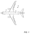
- FIG. 1 An aircraft 10 is shown in FIG. 1 .
- the aircraft 10 has a fuselage 11.
- the fuselage 11 is generally cylindrical and defines a longitudinal axis 12.
- a cargo area is comprised inside the fuselage 11, and is delimited by cargo walls. These cargo walls comprise lateral cargo walls, generally vertical, cargo ceiling and cargo floor, generally horizontal. Referring to FIGS. 2 and 4 , part of a cargo floor 20 of this cargo area is shown.
- the cargo floor 20 may be assembled with the aircraft 10 or may be retrofitted into the aircraft 10.
- the cargo area 12 is defined above the cargo floor 20, and a bilge space 13 is defined below the cargo floor 20.
- the cargo floor 20 divides the cargo area 12 from the bilge space 13.
- the cargo floor 20 comprises a floor substructure 21.
- the floor substructure 21 comprises an array of beams, or rails 30.
- Rails 30 are shown in FIGS. 2 and 4 , and are identified as rails 30a, 30b, 30c, 30d. It will be understood that the number of rails 30 may differ. For example, in one embodiment the cargo floor 20 has two rails 30 only.
- the floor substructure 21 comprises an array of bilge crossbeams 40.
- the bilge crossbeams 40 extend across the fuselage 11. That is, the bilge crossbeams 40 extend in a transverse direction to the longitudinal axis of the fuselage 11. In the present embodiment, the bilge crossbeams 40 extend perpendicular to the longitudinal axis of the fuselage 11.
- the bilge crossbeams 40 are elongate and are supported at points along their length. Each bilge crossbeam 40 has a top face 41. The number of bilge crossbeams 40 may vary.
- One bilge crossbeam 40 is shown in FIG. 2 .
- the rails 30 extend parallel to, but spaced from, each other. The spacing between the rails 30 may vary. Each pair of rails 30 is separated by a longitudinally extending space 31.
- Each rail 30 extends parallel to the longitudinal axis of the fuselage 11.
- the rails 30 extend perpendicular to the bilge crossbeams 40.
- each rail 30 is a roller-track.
- the arrangement of each rail 30 may vary, and may not be a roller-track.
- the arrangement of one rail 30 may differ from that of the or each adjacent rail 30.
- Each rail 30 is elongate. Although each rail 30 is shown as one elongate member in the present arrangement, it will be understood that each rail 30 may be formed of two or more rail elements which are longitudinally aligned with each other. Such rail elements are fluidly sealable with each other at abutting ends.
- the rail 30 is an elongate member.
- the rail 30 may be formed from an extruded metal, for example.
- the rail 30 has an upstanding body 32.
- a base 33 extends along the body 32.
- the base 33 is at the lower end of the rail 30.
- the body 32 is generally U-shaped, with the base 33 and two upstanding walls 34 defining the body 32.
- the walls 34 upstand from the base 33.
- the body 32 defines a channel 35.
- the channel 35 is elongate.
- the channel 35 has a mouth 36.
- the mouth 36 extends along the length of the rail 30.
- the mouth 36 is open at the upper end of the rail 30.
- Rollers 37 are received in the mouth 36.
- One such roller 37 is shown in FIG. 2 .
- the rollers 37 protrude from the mouth 36.
- the rollers 37 are rotatably mounted to the body 32 by a shaft (not shown).
- the rollers 37 are free to rotate.
- the rollers 37 are spaced along the longitudinal length of the rail 30. It will be understood that in some rails 30, the rollers 37 maybe omitted.
- the rail 30 is fixedly mounted to the or each crossbeam 40 by a fixing (not shown). Such fixings are known.
- the fixing extends through the base 33 to the crossbeam 40. With such a fixing arrangement the rail 30 is fixedly mounted in the fuselage 11.
- the rail 30 has a lower flange.
- the lower flange is a first lower flange 38a extending from the lower end of the body 32.
- the first lower flange 38a extends from the lower end of the body 32 at or proximate to the base 33.
- the first lower flange 38a extends from one side of the body 32. In FIG. 2 , the first lower flange 38a is shown extending from the left hand side of the body 32.
- the first lower flange 38a extends along the length of the rail 30.
- the first lower flange 38a acts as a support.
- the rail 30 has a second lower flange 38b extending from the lower end of the body 32.
- the second lower flange 38b extends from the lower end of the body 32 at or proximate to the base 33.
- the second lower flange 38b extends from one side of the body 32.
- second lower flange 38b is shown extending from the right hand side of the body 32.
- the second lower flange 38b extends along the length of the rail 30.
- the second lower flange 38b acts as a support.
- the first and second lower flanges 38a, 38b may form part of the base 33.
- the rail 30 has an upper flange.
- the upper flange is a first upper flange 39a extending from the upper end of the body 32.
- the first upper flange 39a extends from the upper end of the body 32 at or proximate to the mouth 36.
- the first upper flange 39a extends from one side of the body 32. In FIG. 2 , the first upper flange 39a is shown extending from the left hand side of the body 32.
- the first upper flange 39a extends along the length of the rail 30.
- the first upper flange 39a acts as a support.
- the rail 30 has a second upper flange 39b extending from the upper end of the body 32.
- the second upper flange 39b extends from the upper end of the body 32 at or proximate to the mouth 36.
- the second upper flange 39b extends from one side of the body 32. In FIG. 2 , the second upper flange 39b is shown extending from the right hand side of the body 32.
- the second upper flange 39b extends along the length of the rail 30.
- the second upper flange 39b acts as a support.
- the first upper flange 39a is spaced from the first lower flange 38a.
- the first lower and upper flanges 38a, 39a are spaced apart by the wall 34.
- the second upper flange 39b is spaced from the second lower flange 38b.
- the second lower and upper flanges 38b, 39b are spaced apart by the other wall 34 of the body 32.
- the cargo floor 20 further comprises a first, upper, panel 50.
- the cargo floor 20 further comprises a second, lower panel 60.
- the first, upper, panel 50 and second, lower panel 60 are sealably mountable between two adjacent rails 30.
- the first, upper, panel 50 and second, lower panel 60 are spaced from each other to define a fluid duct 70.
- the pair of adjacent rails 30, first, upper, panel 50 and second, lower panel 60 together form a fluid duct 70.
- the fluid duct 70 is elongate and extends longitudinally in the direction of the longitudinal axis of each rail 30.
- FIG. 4 Three first, upper, panels 50 are shown in FIG. 4 .
- One of the first, upper, panels 50 will now be described.
- the first, upper, panel 50 is mountable to the rails 30.
- the first, upper, panel 50 is elongate.
- the first, upper, panel 50 may comprise a plurality of panel sections. An example of two panel sections 50a, 50b is shown in FIG. 4 . Such panel sections 50a, 50b are fluidly sealable to each other along abutting ends.
- the first, upper, panel 50 is configured to be mounted between adjacent rails 30. That is, the first, upper, panel 50 extends between adjacent rails 30.
- the first, upper, panel 50 is configured to extend between one of the upper flanges 39a of one rail 30 and one of the upper flanges 39b of the adjacent rail 30.
- the first, upper, panel 50 is supported by the upper flanges 39a, 39b of adjacent rails 30.
- the first, upper, panel 50 is mounted to the adjacent rails 30 by fixings (not shown). Such fixings for assembling a cargo floor are known and so a detailed description will be omitted.
- the first, upper, panel 50 is disposed on the upper flanges 39a, 39b of adjacent rails 30.
- the first, upper, panel 50 is fluidly sealed with each of the adjacent rails 30.
- a sealing arrangement 54 is provided between the first, upper, panel 50 and the rail 30.
- the first, upper, panel 50 is fluidly sealed with the upper flanges 39a, 39b of adjacent rails 30.
- the first, upper, panel 50 is fluidly sealed with the body 32 of each adjacent rail 30.
- the upper flanges 39a, 39b may have breaks along their length as the upper flanges 39a, 39b act as a support for the first, upper, panel 50 only.
- a lower face 51 of the first, upper, panel 50 faces and abuts the upper flanges 39a, 39b of adjacent rails 30.
- the sealing arrangement 54 is provided between the lower face 51 of the first, upper, panel 50 and the upper flanges 39a, 39b.
- the lower face 51 in the present embodiment the section of the lower face 51 extending between the upper flanges 39a, 39b, forms an inner surface of the fluid duct 70.
- An upper face 52 of the first, upper, panel 50 is exposed and defines a floor surface. Such a floor surface acts as a surface on which to walk and on which cargo items may be placed.
- the upper end of the rails 30 may be configured to lie planar with the upper face 52 of the first, upper, panel 50.
- the second, lower, panel 60 is spaced from the first, upper, panel 50.
- One of the second, lower, panels 60 will now be described.
- the second, lower, panel 60 is mountable to the rails 30.
- the second, lower, panel 60 is elongate.
- the second, lower, panel 60 may comprise a plurality of panel sections. Such panel sections are fluidly sealable to each other along abutting ends.
- the second, lower, panel 60 is configured to be mounted between adjacent rails 30. That is, the second, lower, panel 60 extends between adjacent rails 30.
- the second, lower, panel 60 is configured to extend between one of the lower flanges 38a of one rail 30 and one of the lower flanges 38b of the adjacent rail 30.
- the second, lower, panel 60 is supported by the lower flanges 38a, 38b of adjacent rails 30.
- the second, lower, panel 60 is mounted to the adjacent rails 30 by fixings (not shown). Such fixings for assembling a cargo floor are known and so a detailed description will be omitted.
- the second, lower, panel 60 is disposed on the lower flanges 38a, 38b of adjacent rails 30.
- the second, lower, panel 60 is fluidly sealed with each of the adjacent rails 30.
- a sealing arrangement 64 is provided between the second, lower, panel 60 and the rail 30.
- the second, lower, panel 60 is fluidly sealed with the lower flanges 38a, 38b of adjacent rails 30.
- the second, lower, panel 60 is fluidly sealed with the body 32 of each adjacent rail 30.
- the lower flanges 38a, 38b may have breaks along their length as the lower flanges 38a, 38b act as a support for the second, lower, panel 60 only.
- a lower face 61 of the second, lower, panel 60 faces and abuts the lower flanges 38a, 38b of adjacent rails 30.
- the sealing arrangement 64 is provided between the lower face 61 of the second, lower, panel 60 and the lower flanges 38a, 38b.
- This sealing surface acts to seal the cargo area 12 from the bilge space 13.
- An upper face 52 of the second, lower, panel 60 forms an inner surface of the fluid duct 70.
- the or each fluid duct 70 in the cargo floor 20 is defined by two adjacent rails 30 together with the corresponding first, upper, panel 50 and second, lower, panel 60. These are fluidly sealed with each other to define a fluid-tight passageway.
- each fluid duct 70 in the cargo floor 20 has an inlet 71 and an outlet 72.
- the inlet 71 and outlet 72 are spaced from each other.
- the inlet 71 is disposed at one end of the fluid duct 70, and the outlet is disposed at the other end of the fluid duct 70.
- the inlet 71 comprises an inlet opening to the fluid duct 70.
- An inlet fluid conduit 73 extends from the opening.
- the inlet opening may be formed in one of the rails 30, in the first, upper, panel 50, in the second, lower, panel 60 or at an open end 74 of the fluid duct 70.
- the open end 74 comprises a fluid-tight barrier.
- the outlet 72 comprises an inlet opening to the fluid duct 70.
- An outlet fluid conduit 75 extends from the opening.
- the outlet opening maybe formed in one of the rails 30, in the first, upper, panel 50, in the second, lower, panel 60 or at the other open end 76 of the fluid duct 70.
- the open end 76 comprises a fluid-tight barrier.
- a fluid may be fed into and from the fluid duct 70. Therefore, the fluid duct 70 is able to be fluidly connected to a fluid system (not shown) of the aircraft 10.
- the fluid duct 70 as described above provides a linear path along the fuselage 11 of the aircraft 12.
- the fluid duct 70 By providing the fluid duct 70 between adjacent rails 30, it is possible for the fluid duct 70 to extend along a path over a plurality of bilge crossbeams 40. That is, the second, lower, panel 60 extends over a plurality of bilge crossbeams 40.
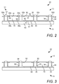
- FIG. 3 an alternative embodiment is shown.
- the arrangement of this embodiment is generally the same as the embodiments described above and so a detailed description will be omitted herein.
- an inlet 80 to the fluid duct 70 comprises an array of apertures 81 disposed along the length of the fluid duct 70.
- Each aperture 81 is formed through one of the rails 30.
- Each aperture 81 extends through one of the walls 34 of the body 32 of the rail 30 to form a fluid path from the channel 35 defined in each rail 30 and the fluid duct 70.
- fluid such as rainwater may also be brought into the cargo area.
- fluid may flow onto the cargo floor 20.
- fluid is able to flow from the cargo floor 20 into the fluid duct 70. Fluid flows from the first, upper, plate 50 into the mouth 36 of one of the rails 30. The fluid then passes from the channel 35 to the fluid duct 70 via the apertures 71. This fluid may then pass along the fluid duct 70 and drained away from the cargo area 12.
- electrical components for example, may be received by the second, lower, plate 60 being sealably mounted to the adjacent rails 30. Therefore, fluid in the cargo area 12 is able to be collected and drained away via the outlet 72 (refer to FIG. 4 ).
- the air in the cargo area 12 must be conditioned by an air conditioning system.
- the conditioned air may be provided through one of the fluid duct 70, and maybe distributed in the cargo area through the aperture 81. In the same way, the air of the cargo area can be aspired in another of the fluid duct 70, through the associated aperture 81.
- fluid ducts 70 With the cargo floor 20 having one or more integrated fluid ducts 70 described herein it is possible to easily segregate the fluid ducts from other systems. Furthermore, such fluid ducts 70 do not require any mounting brackets and so the number of components is minimised.
- the fluid ducts of the invention may be used for the passage of all type of fluids, for example liquids or gas.
- fluid ducts are made in the cargo floor of the cargo area, it will be understood that such fluid ducts may be made identically in each of the cargo walls which delimit the cargo area.
- These cargo walls comprise for example lateral, generally vertical, cargo walls, and cargo ceiling. All these cargo walls may comprise at least two rails spaced from each other, a first panel extending between and fluidly sealed with at least two of the rails, and a second panel extending between and fluidly sealed with at least two of the rails, the first and second panels being spaced from each other to define a fluid duct therebetween.
- rail in the present specification, does not designate specifically a guide rail or a sliding rail. On the contrary, it extends to every type of structural member, like a bar or a beam, able to support panels for making a wall, and to define a fluid duct with these panels and another rail.
Landscapes
- Engineering & Computer Science (AREA)
- Mechanical Engineering (AREA)
- Aviation & Aerospace Engineering (AREA)
- Seal Device For Vehicle (AREA)
- Duct Arrangements (AREA)
Abstract
Description
- The present invention relates to the walls of a cargo area of an aircraft. The present invention also relates to an aircraft having a cargo area.
- In an aircraft it is typically necessary to run pipes and hoses for the passage of fluids, along a fuselage. Such pipes and hoses are received in cavities formed behind walls or under a floor. For example, aircraft typically have a cargo area in the fuselage of the aircraft on which cargo and other items are supported. This cargo area is delimited by cargo walls, and in particular by a cargo floor. Such a cargo floor defines a cargo area above the cargo floor and a bilge space below the cargo floor. Pipes and hoses maybe received in the bilge space.
- However, the available space for receiving pipes and hoses behind, below and/or above the cargo area is limited, and often occupied by other elements of the aircraft such as structure rods, beams, equipment, harnesses, etc. The integration of the pipes and hoses along with other elements is a difficult task for the aircraft manufacturer, and it makes also maintenance task difficult to the aircraft operators. The integration of the pipes and hoses results often in their non-optimized shapes forcing them to take longer paths or creating curves on them. Furthermore, pipes and hoses need to be fixedly mounted to prevent movement of the pipes and hoses. The fixation is achieved by mounting pipes and hoses to the fuselage and/or cargo structure/sub-structure by different fixation means such as brackets. Crowded areas and non-optimized shapes of pipes and horses often result in increase of number of different types of fixation means increasing the complexity of integration and the cost for the production of those fixation means.
- According to a first aspect of the invention there is provided a cargo wall for an aircraft, the cargo wall comprising at least two rails spaced from each other, a first panel extending between and fluidly sealed with at least two of the rails, a second panel extending between and fluidly sealed with at least two of the rails, the first and second panels being spaced from each other to define a fluid duct therebetween.
- With the above arrangement, it is possible to use the cargo wall itself as one or more fluid ducts. Therefore, the number of discrete pipes and hoses required to be received in an aircraft is reduced. Such an arrangement minimises the number of components, such as brackets, required.
- The fluid duct may be fluidly sealed along at least part of its length.
- Therefore, it is possible for the fluid duct to act as a fluid conduit to transport a fluid along a fuselage.
- The fluid duct may comprise an inlet and an outlet.
- The outlet may be formed at one end of the fluid duct.
- The inlet maybe formed at another end of the fluid duct.
- The inlet maybe formed through at least one of the rails.
- The inlet may comprise a plurality of openings in the at least one of the rails.
- The at least two rails may form a wall substructure.
- The wall substructure may comprise at least one crossbeam, wherein the at least two rails are supported by the at least one crossbeam.
- Each of the at least two rails may comprise a body and an upper support. The first panel maybe supported by the upper supports.
- The first panel may be fluidly sealed with the upper supports.
- Each upper support may be a flange.
- Each of the at least two rails may comprise a lower support. The second panel may be supported by the lower supports.
- The second panel may be fluidly sealed with the lower supports.
- Each lower support may be a flange.
- At least one of the at least two rails may comprise a roller track.
- An exposed surface of the first panel may define a wall surface.
- The first and second panels may extend horizontally so as the cargo wall forms the cargo floor of the cargo area.
- According to one aspect of the invention, there is provided an aircraft having a cargo area, and comprising a cargo wall according to the above aspect described above.
- The at least two rails may extend in a longitudinal direction of a fuselage of the aircraft.
- Embodiments of the invention will now be described with reference to the accompanying drawings, in which:
-
FIG 1 is a schematic cross-sectional view of an aircraft; -
FIG. 2 is a schematic cross-sectional view of a cargo floor for an aircraft according to an embodiment of the invention; -
FIG. 3 is a schematic cross-sectional view of another cargo wall for an aircraft according to another embodiment of the invention; and -
FIG. 4 is a schematic plan view of the cargo floor for an aircraft shown inFIG. 2 . - An
aircraft 10 is shown inFIG. 1 . Theaircraft 10 has afuselage 11. Thefuselage 11 is generally cylindrical and defines alongitudinal axis 12. A cargo area is comprised inside thefuselage 11, and is delimited by cargo walls. These cargo walls comprise lateral cargo walls, generally vertical, cargo ceiling and cargo floor, generally horizontal. Referring toFIGS. 2 and4 , part of acargo floor 20 of this cargo area is shown. Thecargo floor 20 may be assembled with theaircraft 10 or may be retrofitted into theaircraft 10. Thecargo area 12 is defined above thecargo floor 20, and abilge space 13 is defined below thecargo floor 20. Thecargo floor 20 divides thecargo area 12 from thebilge space 13. - The
cargo floor 20 comprises afloor substructure 21. Thefloor substructure 21 comprises an array of beams, orrails 30. Fourrails 30 are shown inFIGS. 2 and4 , and are identified asrails rails 30 may differ. For example, in one embodiment thecargo floor 20 has tworails 30 only. - The
floor substructure 21 comprises an array ofbilge crossbeams 40. Thebilge crossbeams 40 extend across thefuselage 11. That is, thebilge crossbeams 40 extend in a transverse direction to the longitudinal axis of thefuselage 11. In the present embodiment, thebilge crossbeams 40 extend perpendicular to the longitudinal axis of thefuselage 11. Thebilge crossbeams 40 are elongate and are supported at points along their length. Eachbilge crossbeam 40 has atop face 41. The number ofbilge crossbeams 40 may vary. Onebilge crossbeam 40 is shown inFIG. 2 . - The
rails 30 extend parallel to, but spaced from, each other. The spacing between therails 30 may vary. Each pair ofrails 30 is separated by alongitudinally extending space 31. - Each
rail 30 extends parallel to the longitudinal axis of thefuselage 11. Therails 30 extend perpendicular to thebilge crossbeams 40. - In the present embodiment, each
rail 30 is a roller-track. However, the arrangement of eachrail 30 may vary, and may not be a roller-track. The arrangement of onerail 30 may differ from that of the or eachadjacent rail 30. - Each
rail 30 is elongate. Although eachrail 30 is shown as one elongate member in the present arrangement, it will be understood that eachrail 30 may be formed of two or more rail elements which are longitudinally aligned with each other. Such rail elements are fluidly sealable with each other at abutting ends. - One of the
rails 30 will now be described in detail. Each of the rails generally has the same arrangement. Therail 30 is an elongate member. Therail 30 may be formed from an extruded metal, for example. Therail 30 has anupstanding body 32. Abase 33 extends along thebody 32. Thebase 33 is at the lower end of therail 30. Thebody 32 is generally U-shaped, with thebase 33 and twoupstanding walls 34 defining thebody 32. Thewalls 34 upstand from thebase 33. Thebody 32 defines achannel 35. Thechannel 35 is elongate. Thechannel 35 has amouth 36. Themouth 36 extends along the length of therail 30. Themouth 36 is open at the upper end of therail 30. -
Rollers 37 are received in themouth 36. Onesuch roller 37 is shown inFIG. 2 . Therollers 37 protrude from themouth 36. Therollers 37 are rotatably mounted to thebody 32 by a shaft (not shown). Therollers 37 are free to rotate. Therollers 37 are spaced along the longitudinal length of therail 30. It will be understood that in somerails 30, therollers 37 maybe omitted. - The
rail 30 is fixedly mounted to the or eachcrossbeam 40 by a fixing (not shown). Such fixings are known. The fixing extends through the base 33 to thecrossbeam 40. With such a fixing arrangement therail 30 is fixedly mounted in thefuselage 11. - The
rail 30 has a lower flange. The lower flange is a firstlower flange 38a extending from the lower end of thebody 32. The firstlower flange 38a extends from the lower end of thebody 32 at or proximate to thebase 33. The firstlower flange 38a extends from one side of thebody 32. InFIG. 2 , the firstlower flange 38a is shown extending from the left hand side of thebody 32. The firstlower flange 38a extends along the length of therail 30. - The first
lower flange 38a acts as a support. - The
rail 30 has a secondlower flange 38b extending from the lower end of thebody 32. The secondlower flange 38b extends from the lower end of thebody 32 at or proximate to thebase 33. The secondlower flange 38b extends from one side of thebody 32. InFIG. 2 , secondlower flange 38b is shown extending from the right hand side of thebody 32. The secondlower flange 38b extends along the length of therail 30. - The second
lower flange 38b acts as a support. The first and secondlower flanges base 33. - The
rail 30 has an upper flange. The upper flange is a firstupper flange 39a extending from the upper end of thebody 32. The firstupper flange 39a extends from the upper end of thebody 32 at or proximate to themouth 36. The firstupper flange 39a extends from one side of thebody 32. InFIG. 2 , the firstupper flange 39a is shown extending from the left hand side of thebody 32. The firstupper flange 39a extends along the length of therail 30. - The first
upper flange 39a acts as a support. - The
rail 30 has a secondupper flange 39b extending from the upper end of thebody 32. The secondupper flange 39b extends from the upper end of thebody 32 at or proximate to themouth 36. The secondupper flange 39b extends from one side of thebody 32. InFIG. 2 , the secondupper flange 39b is shown extending from the right hand side of thebody 32. The secondupper flange 39b extends along the length of therail 30. - The second
upper flange 39b acts as a support. - The first
upper flange 39a is spaced from the firstlower flange 38a. The first lower andupper flanges wall 34. The secondupper flange 39b is spaced from the secondlower flange 38b. The second lower andupper flanges other wall 34 of thebody 32. - The
cargo floor 20 further comprises a first, upper,panel 50. Thecargo floor 20 further comprises a second,lower panel 60. The first, upper,panel 50 and second,lower panel 60 are sealably mountable between twoadjacent rails 30. The first, upper,panel 50 and second,lower panel 60 are spaced from each other to define afluid duct 70. When assembled, the pair ofadjacent rails 30, first, upper,panel 50 and second,lower panel 60 together form afluid duct 70. Thefluid duct 70 is elongate and extends longitudinally in the direction of the longitudinal axis of eachrail 30. - Three first, upper,
panels 50 are shown inFIG. 4 . One of the first, upper,panels 50 will now be described. - The first, upper,
panel 50 is mountable to therails 30. The first, upper,panel 50 is elongate. The first, upper,panel 50 may comprise a plurality of panel sections. An example of twopanel sections FIG. 4 .Such panel sections - The first, upper,
panel 50 is configured to be mounted betweenadjacent rails 30. That is, the first, upper,panel 50 extends betweenadjacent rails 30. The first, upper,panel 50 is configured to extend between one of theupper flanges 39a of onerail 30 and one of theupper flanges 39b of theadjacent rail 30. The first, upper,panel 50 is supported by theupper flanges adjacent rails 30. - The first, upper,
panel 50 is mounted to theadjacent rails 30 by fixings (not shown). Such fixings for assembling a cargo floor are known and so a detailed description will be omitted. - During assembly, the first, upper,
panel 50 is disposed on theupper flanges adjacent rails 30. The first, upper,panel 50 is fluidly sealed with each of the adjacent rails 30. A sealingarrangement 54 is provided between the first, upper,panel 50 and therail 30. In the present embodiment, the first, upper,panel 50 is fluidly sealed with theupper flanges adjacent rails 30. - In one embodiment, the first, upper,
panel 50 is fluidly sealed with thebody 32 of eachadjacent rail 30. In such an arrangement, theupper flanges upper flanges panel 50 only. - A
lower face 51 of the first, upper,panel 50 faces and abuts theupper flanges adjacent rails 30. The sealingarrangement 54 is provided between thelower face 51 of the first, upper,panel 50 and theupper flanges lower face 51, in the present embodiment the section of thelower face 51 extending between theupper flanges fluid duct 70. - An
upper face 52 of the first, upper,panel 50 is exposed and defines a floor surface. Such a floor surface acts as a surface on which to walk and on which cargo items may be placed. The upper end of therails 30 may be configured to lie planar with theupper face 52 of the first, upper,panel 50. - The second, lower,
panel 60 is spaced from the first, upper,panel 50. One of the second, lower,panels 60 will now be described. - The second, lower,
panel 60 is mountable to therails 30. The second, lower,panel 60 is elongate. The second, lower,panel 60 may comprise a plurality of panel sections. Such panel sections are fluidly sealable to each other along abutting ends. - The second, lower,
panel 60 is configured to be mounted betweenadjacent rails 30. That is, the second, lower,panel 60 extends betweenadjacent rails 30. The second, lower,panel 60 is configured to extend between one of thelower flanges 38a of onerail 30 and one of thelower flanges 38b of theadjacent rail 30. The second, lower,panel 60 is supported by thelower flanges adjacent rails 30. - The second, lower,
panel 60 is mounted to theadjacent rails 30 by fixings (not shown). Such fixings for assembling a cargo floor are known and so a detailed description will be omitted. - During assembly, the second, lower,
panel 60 is disposed on thelower flanges adjacent rails 30. The second, lower,panel 60 is fluidly sealed with each of the adjacent rails 30. A sealingarrangement 64 is provided between the second, lower,panel 60 and therail 30. In the present embodiment, the second, lower,panel 60 is fluidly sealed with thelower flanges adjacent rails 30. - In one embodiment, the second, lower,
panel 60 is fluidly sealed with thebody 32 of eachadjacent rail 30. In such an arrangement, thelower flanges lower flanges panel 60 only. - A
lower face 61 of the second, lower,panel 60 faces and abuts thelower flanges adjacent rails 30. The sealingarrangement 64 is provided between thelower face 61 of the second, lower,panel 60 and thelower flanges - The second, lower,
panels 60 together with thebase 33 of eachrail 30 together form a sealing surface. This sealing surface acts to seal thecargo area 12 from thebilge space 13. - An
upper face 52 of the second, lower,panel 60 forms an inner surface of thefluid duct 70. - When assembled, the or each
fluid duct 70 in thecargo floor 20 is defined by twoadjacent rails 30 together with the corresponding first, upper,panel 50 and second, lower,panel 60. These are fluidly sealed with each other to define a fluid-tight passageway. - Referring to
FIG. 4 , eachfluid duct 70 in thecargo floor 20 has aninlet 71 and anoutlet 72. Theinlet 71 andoutlet 72 are spaced from each other. Theinlet 71 is disposed at one end of thefluid duct 70, and the outlet is disposed at the other end of thefluid duct 70. Theinlet 71 comprises an inlet opening to thefluid duct 70. Aninlet fluid conduit 73 extends from the opening. The inlet opening may be formed in one of therails 30, in the first, upper,panel 50, in the second, lower,panel 60 or at anopen end 74 of thefluid duct 70. Theopen end 74 comprises a fluid-tight barrier. - The
outlet 72 comprises an inlet opening to thefluid duct 70. Anoutlet fluid conduit 75 extends from the opening. The outlet opening maybe formed in one of therails 30, in the first, upper,panel 50, in the second, lower,panel 60 or at the otheropen end 76 of thefluid duct 70. Theopen end 76 comprises a fluid-tight barrier. - With the above described arrangement, a fluid may be fed into and from the
fluid duct 70. Therefore, thefluid duct 70 is able to be fluidly connected to a fluid system (not shown) of theaircraft 10. - The
fluid duct 70 as described above provides a linear path along thefuselage 11 of theaircraft 12. By providing thefluid duct 70 betweenadjacent rails 30, it is possible for thefluid duct 70 to extend along a path over a plurality ofbilge crossbeams 40. That is, the second, lower,panel 60 extends over a plurality ofbilge crossbeams 40. - Referring to
FIG. 3 , an alternative embodiment is shown. The arrangement of this embodiment is generally the same as the embodiments described above and so a detailed description will be omitted herein. - In the embodiment of
FIG. 3 , aninlet 80 to thefluid duct 70 comprises an array ofapertures 81 disposed along the length of thefluid duct 70. Eachaperture 81 is formed through one of therails 30. Eachaperture 81 extends through one of thewalls 34 of thebody 32 of therail 30 to form a fluid path from thechannel 35 defined in eachrail 30 and thefluid duct 70. - When cargo is brought into the
cargo area 12, fluid such as rainwater may also be brought into the cargo area. Such fluid may flow onto thecargo floor 20. With this arrangement, fluid is able to flow from thecargo floor 20 into thefluid duct 70. Fluid flows from the first, upper,plate 50 into themouth 36 of one of therails 30. The fluid then passes from thechannel 35 to thefluid duct 70 via theapertures 71. This fluid may then pass along thefluid duct 70 and drained away from thecargo area 12. However, such fluid is prevented from flowing into thebilge space 13 in which electrical components, for example, may be received by the second, lower,plate 60 being sealably mounted to the adjacent rails 30. Therefore, fluid in thecargo area 12 is able to be collected and drained away via the outlet 72 (refer toFIG. 4 ). - When the aircraft is flying, the air in the
cargo area 12 must be conditioned by an air conditioning system. The conditioned air may be provided through one of thefluid duct 70, and maybe distributed in the cargo area through theaperture 81. In the same way, the air of the cargo area can be aspired in another of thefluid duct 70, through the associatedaperture 81. - With the
cargo floor 20 having one or moreintegrated fluid ducts 70 described herein it is possible to easily segregate the fluid ducts from other systems. Furthermore,such fluid ducts 70 do not require any mounting brackets and so the number of components is minimised. - The fluid ducts of the invention may be used for the passage of all type of fluids, for example liquids or gas.
- Although in the present embodiment the fluid ducts are made in the cargo floor of the cargo area, it will be understood that such fluid ducts may be made identically in each of the cargo walls which delimit the cargo area. These cargo walls comprise for example lateral, generally vertical, cargo walls, and cargo ceiling. All these cargo walls may comprise at least two rails spaced from each other, a first panel extending between and fluidly sealed with at least two of the rails, and a second panel extending between and fluidly sealed with at least two of the rails, the first and second panels being spaced from each other to define a fluid duct therebetween.
- The word "rail", in the present specification, does not designate specifically a guide rail or a sliding rail. On the contrary, it extends to every type of structural member, like a bar or a beam, able to support panels for making a wall, and to define a fluid duct with these panels and another rail.
- Although the invention has been described above with reference to one or more preferred embodiments, it will be appreciated that various changes or modifications may be made without departing from the scope of the invention as defined in the appended claims.
Claims (20)
- A cargo wall for an aircraft, the cargo wall comprising:at least two rails spaced from each other,a first panel extending between and fluidly sealed with at least two of the rails,a second panel extending between and fluidly sealed with at least two of the rails,the first and second panels being spaced from each other to define a fluid duct therebetween.
- The cargo wall according to claim 1, wherein the fluid duct is fluidly sealed along at least part of its length.
- The cargo wall according to claim 2, wherein the fluid duct comprises an inlet and an outlet.
- The cargo wall according to claim 3, wherein the outlet is formed at one end of the fluid duct.
- The cargo wall according to claim 4, wherein the inlet is formed at another end of the fluid duct.
- The cargo wall according to claim 3 or claim 4, wherein the inlet is formed through at least one of the rails.
- The cargo wall according to claim 6, wherein the inlet comprises a plurality of openings in the at least one of the rails.
- The cargo wall according to claim 1, wherein the at least two rails form a wall substructure.
- The cargo wall according to claim 8, wherein the wall substructure comprises at least one crossbeam, wherein the at least two rails are supported by the at least one crossbeam.
- The cargo wall according to any one of the preceding claims, wherein each of the at least two rails comprises a body and an upper support, the first panel being supported by the upper supports.
- The cargo wall according to claim 10, wherein the first panel is fluidly sealed with the upper supports.
- The cargo wall according to claim 10 or claim 11, wherein each upper support is a flange.
- The cargo wall according to any one of claims 10, 11 or 12, wherein each of the at least two rails comprises a lower support, the second panel being supported by the lower supports.
- The cargo wall according to claim 13, wherein the second panel is fluidly sealed with the lower supports.
- The cargo wall according to claim 13 or claim 14, wherein each lower support is a flange.
- The cargo wall according to any one of the preceding claims, wherein at least one of the at least two rails comprises a roller track.
- The cargo wall according to any one of the preceding claims, wherein the first panel defines a wall surface.
- The cargo wall according to any one of the preceding claims, wherein the first and second panels extend horizontally, the cargo wall forming the floor of the cargo area.
- An aircraft having a cargo area delimited by cargo walls, and comprising a cargo wall according to any one of the preceding claims.
- The aircraft according to claim 19, wherein the at least two rails extend in a longitudinal direction of a fuselage of the aircraft.
Priority Applications (1)
| Application Number | Priority Date | Filing Date | Title |
|---|---|---|---|
| EP15306803.6A EP3168141B1 (en) | 2015-11-13 | 2015-11-13 | A cargo floor or wall for an aircraft |
Applications Claiming Priority (1)
| Application Number | Priority Date | Filing Date | Title |
|---|---|---|---|
| EP15306803.6A EP3168141B1 (en) | 2015-11-13 | 2015-11-13 | A cargo floor or wall for an aircraft |
Publications (2)
| Publication Number | Publication Date |
|---|---|
| EP3168141A1 true EP3168141A1 (en) | 2017-05-17 |
| EP3168141B1 EP3168141B1 (en) | 2019-04-24 |
Family
ID=54601712
Family Applications (1)
| Application Number | Title | Priority Date | Filing Date |
|---|---|---|---|
| EP15306803.6A Active EP3168141B1 (en) | 2015-11-13 | 2015-11-13 | A cargo floor or wall for an aircraft |
Country Status (1)
| Country | Link |
|---|---|
| EP (1) | EP3168141B1 (en) |
Citations (4)
| Publication number | Priority date | Publication date | Assignee | Title |
|---|---|---|---|---|
| DE29724813U1 (en) * | 1997-03-10 | 2004-04-29 | Telair International Gmbh | floor element |
| WO2005012085A1 (en) * | 2003-07-18 | 2005-02-10 | Telair International Gmbh | Floor for an aircraft cargo compartment an a method for the assembly thereof |
| JP2005206139A (en) * | 2003-12-24 | 2005-08-04 | Kobe Steel Ltd | Aluminum extrusion material for floor structure for vehicle |
| WO2011009474A1 (en) * | 2009-07-21 | 2011-01-27 | Telair International Gmbh | Floor element for a loading deck of an aircraft |
-
2015
- 2015-11-13 EP EP15306803.6A patent/EP3168141B1/en active Active
Patent Citations (4)
| Publication number | Priority date | Publication date | Assignee | Title |
|---|---|---|---|---|
| DE29724813U1 (en) * | 1997-03-10 | 2004-04-29 | Telair International Gmbh | floor element |
| WO2005012085A1 (en) * | 2003-07-18 | 2005-02-10 | Telair International Gmbh | Floor for an aircraft cargo compartment an a method for the assembly thereof |
| JP2005206139A (en) * | 2003-12-24 | 2005-08-04 | Kobe Steel Ltd | Aluminum extrusion material for floor structure for vehicle |
| WO2011009474A1 (en) * | 2009-07-21 | 2011-01-27 | Telair International Gmbh | Floor element for a loading deck of an aircraft |
Also Published As
| Publication number | Publication date |
|---|---|
| EP3168141B1 (en) | 2019-04-24 |
Similar Documents
| Publication | Publication Date | Title |
|---|---|---|
| US9440661B2 (en) | Integrated ceiling assembly for railcars | |
| JP6694329B2 (en) | Air conditioning duct for railway vehicles | |
| EP1930211B2 (en) | Commercial vehicle superstructure and commercial vehicle with such a superstructure | |
| CA2591161C (en) | Arrangement of line connections for installations in an aircraft passenger cabin | |
| US20060185321A1 (en) | Aseptic packaging installation with aseptic buffer zones | |
| EP3362395B1 (en) | Car for a lift in a lift shaft | |
| CN113002754A (en) | Aircraft fuselage section, aircraft and installation method | |
| EP3168141B1 (en) | A cargo floor or wall for an aircraft | |
| EP1950167A1 (en) | Ventilation system for a lift cabin and lift cabin and lift cabin with such a ventilation system | |
| US20150344045A1 (en) | Vehicle air-conditioning system and railroad vehicle equipped with same | |
| US20200276605A1 (en) | Installation and method for coating objects | |
| EP2354686B1 (en) | Ceiling air outlet or an air conditioner for supply air and inducing recirculating room air in horizontal direction | |
| US20160347437A1 (en) | Structure to support equipment in a fuselage of an aircraft | |
| US9433325B2 (en) | Sliding shower door guide and drain assembly | |
| EP3167954B1 (en) | Static mixer | |
| US20180118518A1 (en) | Elevator safety gear alignment system and method | |
| EP3736193B1 (en) | Passenger transport vehicle with an air-conditioning system | |
| KR20210095585A (en) | Rail engine with technical equipment attachment device | |
| EP3002173A1 (en) | Rail vehicle with a roof air conditioning channel | |
| DE19640741A1 (en) | Air flow guidance system within an aircraft door area | |
| EP2599939A1 (en) | Modular structure for working spaces, in particular laboratories, adaptable to different volumes and installations | |
| AU2016202611B2 (en) | An air conditioning device for an homogeneous air conditioning of a carriage of a railway vehicle | |
| JP4970454B2 (en) | Air conveyor | |
| EP3067274B1 (en) | Duct assembly and method of assembling thereof | |
| US10899370B2 (en) | Paneling modules for vehicles |
Legal Events
| Date | Code | Title | Description |
|---|---|---|---|
| PUAI | Public reference made under article 153(3) epc to a published international application that has entered the european phase |
Free format text: ORIGINAL CODE: 0009012 |
|
| STAA | Information on the status of an ep patent application or granted ep patent |
Free format text: STATUS: THE APPLICATION HAS BEEN PUBLISHED |
|
| AK | Designated contracting states |
Kind code of ref document: A1 Designated state(s): AL AT BE BG CH CY CZ DE DK EE ES FI FR GB GR HR HU IE IS IT LI LT LU LV MC MK MT NL NO PL PT RO RS SE SI SK SM TR |
|
| AX | Request for extension of the european patent |
Extension state: BA ME |
|
| RAP1 | Party data changed (applicant data changed or rights of an application transferred) |
Owner name: AIRBUS (S.A.S.) Owner name: AIRBUS OPERATIONS (S.A.S) Owner name: AIRBUS OPERATIONS GMBH |
|
| STAA | Information on the status of an ep patent application or granted ep patent |
Free format text: STATUS: REQUEST FOR EXAMINATION WAS MADE |
|
| 17P | Request for examination filed |
Effective date: 20171117 |
|
| RBV | Designated contracting states (corrected) |
Designated state(s): AL AT BE BG CH CY CZ DE DK EE ES FI FR GB GR HR HU IE IS IT LI LT LU LV MC MK MT NL NO PL PT RO RS SE SI SK SM TR |
|
| GRAP | Despatch of communication of intention to grant a patent |
Free format text: ORIGINAL CODE: EPIDOSNIGR1 |
|
| STAA | Information on the status of an ep patent application or granted ep patent |
Free format text: STATUS: GRANT OF PATENT IS INTENDED |
|
| INTG | Intention to grant announced |
Effective date: 20181129 |
|
| GRAS | Grant fee paid |
Free format text: ORIGINAL CODE: EPIDOSNIGR3 |
|
| GRAJ | Information related to disapproval of communication of intention to grant by the applicant or resumption of examination proceedings by the epo deleted |
Free format text: ORIGINAL CODE: EPIDOSDIGR1 |
|
| GRAL | Information related to payment of fee for publishing/printing deleted |
Free format text: ORIGINAL CODE: EPIDOSDIGR3 |
|
| STAA | Information on the status of an ep patent application or granted ep patent |
Free format text: STATUS: REQUEST FOR EXAMINATION WAS MADE |
|
| GRAR | Information related to intention to grant a patent recorded |
Free format text: ORIGINAL CODE: EPIDOSNIGR71 |
|
| STAA | Information on the status of an ep patent application or granted ep patent |
Free format text: STATUS: GRANT OF PATENT IS INTENDED |
|
| INTC | Intention to grant announced (deleted) | ||
| GRAA | (expected) grant |
Free format text: ORIGINAL CODE: 0009210 |
|
| STAA | Information on the status of an ep patent application or granted ep patent |
Free format text: STATUS: THE PATENT HAS BEEN GRANTED |
|
| INTG | Intention to grant announced |
Effective date: 20190312 |
|
| AK | Designated contracting states |
Kind code of ref document: B1 Designated state(s): AL AT BE BG CH CY CZ DE DK EE ES FI FR GB GR HR HU IE IS IT LI LT LU LV MC MK MT NL NO PL PT RO RS SE SI SK SM TR |
|
| REG | Reference to a national code |
Ref country code: GB Ref legal event code: FG4D |
|
| REG | Reference to a national code |
Ref country code: CH Ref legal event code: EP |
|
| REG | Reference to a national code |
Ref country code: AT Ref legal event code: REF Ref document number: 1123833 Country of ref document: AT Kind code of ref document: T Effective date: 20190515 Ref country code: IE Ref legal event code: FG4D |
|
| REG | Reference to a national code |
Ref country code: DE Ref legal event code: R096 Ref document number: 602015028796 Country of ref document: DE |
|
| REG | Reference to a national code |
Ref country code: NL Ref legal event code: MP Effective date: 20190424 |
|
| REG | Reference to a national code |
Ref country code: LT Ref legal event code: MG4D |
|
| PG25 | Lapsed in a contracting state [announced via postgrant information from national office to epo] |
Ref country code: NL Free format text: LAPSE BECAUSE OF FAILURE TO SUBMIT A TRANSLATION OF THE DESCRIPTION OR TO PAY THE FEE WITHIN THE PRESCRIBED TIME-LIMIT Effective date: 20190424 |
|
| PG25 | Lapsed in a contracting state [announced via postgrant information from national office to epo] |
Ref country code: FI Free format text: LAPSE BECAUSE OF FAILURE TO SUBMIT A TRANSLATION OF THE DESCRIPTION OR TO PAY THE FEE WITHIN THE PRESCRIBED TIME-LIMIT Effective date: 20190424 Ref country code: SE Free format text: LAPSE BECAUSE OF FAILURE TO SUBMIT A TRANSLATION OF THE DESCRIPTION OR TO PAY THE FEE WITHIN THE PRESCRIBED TIME-LIMIT Effective date: 20190424 Ref country code: ES Free format text: LAPSE BECAUSE OF FAILURE TO SUBMIT A TRANSLATION OF THE DESCRIPTION OR TO PAY THE FEE WITHIN THE PRESCRIBED TIME-LIMIT Effective date: 20190424 Ref country code: LT Free format text: LAPSE BECAUSE OF FAILURE TO SUBMIT A TRANSLATION OF THE DESCRIPTION OR TO PAY THE FEE WITHIN THE PRESCRIBED TIME-LIMIT Effective date: 20190424 Ref country code: AL Free format text: LAPSE BECAUSE OF FAILURE TO SUBMIT A TRANSLATION OF THE DESCRIPTION OR TO PAY THE FEE WITHIN THE PRESCRIBED TIME-LIMIT Effective date: 20190424 Ref country code: PT Free format text: LAPSE BECAUSE OF FAILURE TO SUBMIT A TRANSLATION OF THE DESCRIPTION OR TO PAY THE FEE WITHIN THE PRESCRIBED TIME-LIMIT Effective date: 20190824 Ref country code: NO Free format text: LAPSE BECAUSE OF FAILURE TO SUBMIT A TRANSLATION OF THE DESCRIPTION OR TO PAY THE FEE WITHIN THE PRESCRIBED TIME-LIMIT Effective date: 20190724 Ref country code: HR Free format text: LAPSE BECAUSE OF FAILURE TO SUBMIT A TRANSLATION OF THE DESCRIPTION OR TO PAY THE FEE WITHIN THE PRESCRIBED TIME-LIMIT Effective date: 20190424 |
|
| PG25 | Lapsed in a contracting state [announced via postgrant information from national office to epo] |
Ref country code: BG Free format text: LAPSE BECAUSE OF FAILURE TO SUBMIT A TRANSLATION OF THE DESCRIPTION OR TO PAY THE FEE WITHIN THE PRESCRIBED TIME-LIMIT Effective date: 20190724 Ref country code: PL Free format text: LAPSE BECAUSE OF FAILURE TO SUBMIT A TRANSLATION OF THE DESCRIPTION OR TO PAY THE FEE WITHIN THE PRESCRIBED TIME-LIMIT Effective date: 20190424 Ref country code: GR Free format text: LAPSE BECAUSE OF FAILURE TO SUBMIT A TRANSLATION OF THE DESCRIPTION OR TO PAY THE FEE WITHIN THE PRESCRIBED TIME-LIMIT Effective date: 20190725 Ref country code: RS Free format text: LAPSE BECAUSE OF FAILURE TO SUBMIT A TRANSLATION OF THE DESCRIPTION OR TO PAY THE FEE WITHIN THE PRESCRIBED TIME-LIMIT Effective date: 20190424 Ref country code: LV Free format text: LAPSE BECAUSE OF FAILURE TO SUBMIT A TRANSLATION OF THE DESCRIPTION OR TO PAY THE FEE WITHIN THE PRESCRIBED TIME-LIMIT Effective date: 20190424 |
|
| REG | Reference to a national code |
Ref country code: AT Ref legal event code: MK05 Ref document number: 1123833 Country of ref document: AT Kind code of ref document: T Effective date: 20190424 |
|
| PG25 | Lapsed in a contracting state [announced via postgrant information from national office to epo] |
Ref country code: IS Free format text: LAPSE BECAUSE OF FAILURE TO SUBMIT A TRANSLATION OF THE DESCRIPTION OR TO PAY THE FEE WITHIN THE PRESCRIBED TIME-LIMIT Effective date: 20190824 |
|
| REG | Reference to a national code |
Ref country code: DE Ref legal event code: R097 Ref document number: 602015028796 Country of ref document: DE |
|
| PG25 | Lapsed in a contracting state [announced via postgrant information from national office to epo] |
Ref country code: CZ Free format text: LAPSE BECAUSE OF FAILURE TO SUBMIT A TRANSLATION OF THE DESCRIPTION OR TO PAY THE FEE WITHIN THE PRESCRIBED TIME-LIMIT Effective date: 20190424 Ref country code: RO Free format text: LAPSE BECAUSE OF FAILURE TO SUBMIT A TRANSLATION OF THE DESCRIPTION OR TO PAY THE FEE WITHIN THE PRESCRIBED TIME-LIMIT Effective date: 20190424 Ref country code: DK Free format text: LAPSE BECAUSE OF FAILURE TO SUBMIT A TRANSLATION OF THE DESCRIPTION OR TO PAY THE FEE WITHIN THE PRESCRIBED TIME-LIMIT Effective date: 20190424 Ref country code: AT Free format text: LAPSE BECAUSE OF FAILURE TO SUBMIT A TRANSLATION OF THE DESCRIPTION OR TO PAY THE FEE WITHIN THE PRESCRIBED TIME-LIMIT Effective date: 20190424 Ref country code: EE Free format text: LAPSE BECAUSE OF FAILURE TO SUBMIT A TRANSLATION OF THE DESCRIPTION OR TO PAY THE FEE WITHIN THE PRESCRIBED TIME-LIMIT Effective date: 20190424 Ref country code: SK Free format text: LAPSE BECAUSE OF FAILURE TO SUBMIT A TRANSLATION OF THE DESCRIPTION OR TO PAY THE FEE WITHIN THE PRESCRIBED TIME-LIMIT Effective date: 20190424 |
|
| PG25 | Lapsed in a contracting state [announced via postgrant information from national office to epo] |
Ref country code: IT Free format text: LAPSE BECAUSE OF FAILURE TO SUBMIT A TRANSLATION OF THE DESCRIPTION OR TO PAY THE FEE WITHIN THE PRESCRIBED TIME-LIMIT Effective date: 20190424 Ref country code: SM Free format text: LAPSE BECAUSE OF FAILURE TO SUBMIT A TRANSLATION OF THE DESCRIPTION OR TO PAY THE FEE WITHIN THE PRESCRIBED TIME-LIMIT Effective date: 20190424 |
|
| PLBE | No opposition filed within time limit |
Free format text: ORIGINAL CODE: 0009261 |
|
| STAA | Information on the status of an ep patent application or granted ep patent |
Free format text: STATUS: NO OPPOSITION FILED WITHIN TIME LIMIT |
|
| PG25 | Lapsed in a contracting state [announced via postgrant information from national office to epo] |
Ref country code: TR Free format text: LAPSE BECAUSE OF FAILURE TO SUBMIT A TRANSLATION OF THE DESCRIPTION OR TO PAY THE FEE WITHIN THE PRESCRIBED TIME-LIMIT Effective date: 20190424 |
|
| 26N | No opposition filed |
Effective date: 20200127 |
|
| PG25 | Lapsed in a contracting state [announced via postgrant information from national office to epo] |
Ref country code: SI Free format text: LAPSE BECAUSE OF FAILURE TO SUBMIT A TRANSLATION OF THE DESCRIPTION OR TO PAY THE FEE WITHIN THE PRESCRIBED TIME-LIMIT Effective date: 20190424 |
|
| REG | Reference to a national code |
Ref country code: CH Ref legal event code: PL |
|
| PG25 | Lapsed in a contracting state [announced via postgrant information from national office to epo] |
Ref country code: CH Free format text: LAPSE BECAUSE OF NON-PAYMENT OF DUE FEES Effective date: 20191130 Ref country code: LU Free format text: LAPSE BECAUSE OF NON-PAYMENT OF DUE FEES Effective date: 20191113 Ref country code: LI Free format text: LAPSE BECAUSE OF NON-PAYMENT OF DUE FEES Effective date: 20191130 Ref country code: MC Free format text: LAPSE BECAUSE OF FAILURE TO SUBMIT A TRANSLATION OF THE DESCRIPTION OR TO PAY THE FEE WITHIN THE PRESCRIBED TIME-LIMIT Effective date: 20190424 |
|
| REG | Reference to a national code |
Ref country code: BE Ref legal event code: MM Effective date: 20191130 |
|
| PG25 | Lapsed in a contracting state [announced via postgrant information from national office to epo] |
Ref country code: IE Free format text: LAPSE BECAUSE OF NON-PAYMENT OF DUE FEES Effective date: 20191113 |
|
| PG25 | Lapsed in a contracting state [announced via postgrant information from national office to epo] |
Ref country code: BE Free format text: LAPSE BECAUSE OF NON-PAYMENT OF DUE FEES Effective date: 20191130 |
|
| PG25 | Lapsed in a contracting state [announced via postgrant information from national office to epo] |
Ref country code: CY Free format text: LAPSE BECAUSE OF FAILURE TO SUBMIT A TRANSLATION OF THE DESCRIPTION OR TO PAY THE FEE WITHIN THE PRESCRIBED TIME-LIMIT Effective date: 20190424 |
|
| PG25 | Lapsed in a contracting state [announced via postgrant information from national office to epo] |
Ref country code: MT Free format text: LAPSE BECAUSE OF FAILURE TO SUBMIT A TRANSLATION OF THE DESCRIPTION OR TO PAY THE FEE WITHIN THE PRESCRIBED TIME-LIMIT Effective date: 20190424 Ref country code: HU Free format text: LAPSE BECAUSE OF FAILURE TO SUBMIT A TRANSLATION OF THE DESCRIPTION OR TO PAY THE FEE WITHIN THE PRESCRIBED TIME-LIMIT; INVALID AB INITIO Effective date: 20151113 |
|
| PG25 | Lapsed in a contracting state [announced via postgrant information from national office to epo] |
Ref country code: MK Free format text: LAPSE BECAUSE OF FAILURE TO SUBMIT A TRANSLATION OF THE DESCRIPTION OR TO PAY THE FEE WITHIN THE PRESCRIBED TIME-LIMIT Effective date: 20190424 |
|
| PGFP | Annual fee paid to national office [announced via postgrant information from national office to epo] |
Ref country code: DE Payment date: 20251119 Year of fee payment: 11 |
|
| PGFP | Annual fee paid to national office [announced via postgrant information from national office to epo] |
Ref country code: GB Payment date: 20251120 Year of fee payment: 11 |
|
| PGFP | Annual fee paid to national office [announced via postgrant information from national office to epo] |
Ref country code: FR Payment date: 20251126 Year of fee payment: 11 |