EP3167954A1 - Static mixer - Google Patents
Static mixer Download PDFInfo
- Publication number
- EP3167954A1 EP3167954A1 EP16198408.3A EP16198408A EP3167954A1 EP 3167954 A1 EP3167954 A1 EP 3167954A1 EP 16198408 A EP16198408 A EP 16198408A EP 3167954 A1 EP3167954 A1 EP 3167954A1
- Authority
- EP
- European Patent Office
- Prior art keywords
- unit plates
- static mixer
- gases
- discharge part
- hollow portion
- Prior art date
- Legal status (The legal status is an assumption and is not a legal conclusion. Google has not performed a legal analysis and makes no representation as to the accuracy of the status listed.)
- Granted
Links
Images






Classifications
-
- B—PERFORMING OPERATIONS; TRANSPORTING
- B01—PHYSICAL OR CHEMICAL PROCESSES OR APPARATUS IN GENERAL
- B01F—MIXING, e.g. DISSOLVING, EMULSIFYING OR DISPERSING
- B01F25/00—Flow mixers; Mixers for falling materials, e.g. solid particles
- B01F25/40—Static mixers
- B01F25/42—Static mixers in which the mixing is affected by moving the components jointly in changing directions, e.g. in tubes provided with baffles or obstructions
- B01F25/421—Static mixers in which the mixing is affected by moving the components jointly in changing directions, e.g. in tubes provided with baffles or obstructions by moving the components in a convoluted or labyrinthine path
- B01F25/422—Static mixers in which the mixing is affected by moving the components jointly in changing directions, e.g. in tubes provided with baffles or obstructions by moving the components in a convoluted or labyrinthine path between stacked plates, e.g. grooved or perforated plates
-
- B—PERFORMING OPERATIONS; TRANSPORTING
- B01—PHYSICAL OR CHEMICAL PROCESSES OR APPARATUS IN GENERAL
- B01D—SEPARATION
- B01D53/00—Separation of gases or vapours; Recovering vapours of volatile solvents from gases; Chemical or biological purification of waste gases, e.g. engine exhaust gases, smoke, fumes, flue gases, aerosols
- B01D53/34—Chemical or biological purification of waste gases
- B01D53/74—General processes for purification of waste gases; Apparatus or devices specially adapted therefor
- B01D53/86—Catalytic processes
- B01D53/8621—Removing nitrogen compounds
- B01D53/8625—Nitrogen oxides
- B01D53/8631—Processes characterised by a specific device
-
- B—PERFORMING OPERATIONS; TRANSPORTING
- B01—PHYSICAL OR CHEMICAL PROCESSES OR APPARATUS IN GENERAL
- B01F—MIXING, e.g. DISSOLVING, EMULSIFYING OR DISPERSING
- B01F23/00—Mixing according to the phases to be mixed, e.g. dispersing or emulsifying
- B01F23/10—Mixing gases with gases
-
- B—PERFORMING OPERATIONS; TRANSPORTING
- B01—PHYSICAL OR CHEMICAL PROCESSES OR APPARATUS IN GENERAL
- B01F—MIXING, e.g. DISSOLVING, EMULSIFYING OR DISPERSING
- B01F23/00—Mixing according to the phases to be mixed, e.g. dispersing or emulsifying
- B01F23/10—Mixing gases with gases
- B01F23/19—Mixing systems, i.e. flow charts or diagrams; Arrangements, e.g. comprising controlling means
-
- B—PERFORMING OPERATIONS; TRANSPORTING
- B01—PHYSICAL OR CHEMICAL PROCESSES OR APPARATUS IN GENERAL
- B01F—MIXING, e.g. DISSOLVING, EMULSIFYING OR DISPERSING
- B01F25/00—Flow mixers; Mixers for falling materials, e.g. solid particles
- B01F25/12—Interdigital mixers, i.e. the substances to be mixed are divided in sub-streams which are rearranged in an interdigital or interspersed manner
-
- B—PERFORMING OPERATIONS; TRANSPORTING
- B01—PHYSICAL OR CHEMICAL PROCESSES OR APPARATUS IN GENERAL
- B01F—MIXING, e.g. DISSOLVING, EMULSIFYING OR DISPERSING
- B01F25/00—Flow mixers; Mixers for falling materials, e.g. solid particles
- B01F25/30—Injector mixers
- B01F25/31—Injector mixers in conduits or tubes through which the main component flows
-
- B—PERFORMING OPERATIONS; TRANSPORTING
- B01—PHYSICAL OR CHEMICAL PROCESSES OR APPARATUS IN GENERAL
- B01F—MIXING, e.g. DISSOLVING, EMULSIFYING OR DISPERSING
- B01F25/00—Flow mixers; Mixers for falling materials, e.g. solid particles
- B01F25/40—Static mixers
- B01F25/42—Static mixers in which the mixing is affected by moving the components jointly in changing directions, e.g. in tubes provided with baffles or obstructions
- B01F25/43—Mixing tubes, e.g. wherein the material is moved in a radial or partly reversed direction
- B01F25/431—Straight mixing tubes with baffles or obstructions that do not cause substantial pressure drop; Baffles therefor
- B01F25/4316—Straight mixing tubes with baffles or obstructions that do not cause substantial pressure drop; Baffles therefor the baffles being flat pieces of material, e.g. intermeshing, fixed to the wall or fixed on a central rod
- B01F25/43161—Straight mixing tubes with baffles or obstructions that do not cause substantial pressure drop; Baffles therefor the baffles being flat pieces of material, e.g. intermeshing, fixed to the wall or fixed on a central rod composed of consecutive sections of flat pieces of material
-
- F—MECHANICAL ENGINEERING; LIGHTING; HEATING; WEAPONS; BLASTING
- F01—MACHINES OR ENGINES IN GENERAL; ENGINE PLANTS IN GENERAL; STEAM ENGINES
- F01N—GAS-FLOW SILENCERS OR EXHAUST APPARATUS FOR MACHINES OR ENGINES IN GENERAL; GAS-FLOW SILENCERS OR EXHAUST APPARATUS FOR INTERNAL-COMBUSTION ENGINES
- F01N3/00—Exhaust or silencing apparatus having means for purifying, rendering innocuous, or otherwise treating exhaust
- F01N3/08—Exhaust or silencing apparatus having means for purifying, rendering innocuous, or otherwise treating exhaust for rendering innocuous
- F01N3/10—Exhaust or silencing apparatus having means for purifying, rendering innocuous, or otherwise treating exhaust for rendering innocuous by thermal or catalytic conversion of noxious components of exhaust
- F01N3/24—Exhaust or silencing apparatus having means for purifying, rendering innocuous, or otherwise treating exhaust for rendering innocuous by thermal or catalytic conversion of noxious components of exhaust characterised by constructional aspects of converting apparatus
- F01N3/28—Construction of catalytic reactors
- F01N3/2892—Exhaust flow directors or the like, e.g. upstream of catalytic device
-
- B—PERFORMING OPERATIONS; TRANSPORTING
- B01—PHYSICAL OR CHEMICAL PROCESSES OR APPARATUS IN GENERAL
- B01F—MIXING, e.g. DISSOLVING, EMULSIFYING OR DISPERSING
- B01F25/00—Flow mixers; Mixers for falling materials, e.g. solid particles
- B01F2025/91—Direction of flow or arrangement of feed and discharge openings
- B01F2025/911—Axial flow
-
- B—PERFORMING OPERATIONS; TRANSPORTING
- B01—PHYSICAL OR CHEMICAL PROCESSES OR APPARATUS IN GENERAL
- B01F—MIXING, e.g. DISSOLVING, EMULSIFYING OR DISPERSING
- B01F25/00—Flow mixers; Mixers for falling materials, e.g. solid particles
- B01F2025/91—Direction of flow or arrangement of feed and discharge openings
- B01F2025/919—Direction of flow or arrangement of feed and discharge openings characterised by the disposition of the feed and discharge openings
-
- B—PERFORMING OPERATIONS; TRANSPORTING
- B01—PHYSICAL OR CHEMICAL PROCESSES OR APPARATUS IN GENERAL
- B01F—MIXING, e.g. DISSOLVING, EMULSIFYING OR DISPERSING
- B01F25/00—Flow mixers; Mixers for falling materials, e.g. solid particles
- B01F2025/91—Direction of flow or arrangement of feed and discharge openings
- B01F2025/919—Direction of flow or arrangement of feed and discharge openings characterised by the disposition of the feed and discharge openings
- B01F2025/9191—Direction of flow or arrangement of feed and discharge openings characterised by the disposition of the feed and discharge openings characterised by the arrangement of the feed openings for one or more flows, e.g. for the mainflow and the flow of an additional component
-
- B—PERFORMING OPERATIONS; TRANSPORTING
- B01—PHYSICAL OR CHEMICAL PROCESSES OR APPARATUS IN GENERAL
- B01F—MIXING, e.g. DISSOLVING, EMULSIFYING OR DISPERSING
- B01F25/00—Flow mixers; Mixers for falling materials, e.g. solid particles
- B01F25/40—Static mixers
- B01F25/42—Static mixers in which the mixing is affected by moving the components jointly in changing directions, e.g. in tubes provided with baffles or obstructions
- B01F25/43—Mixing tubes, e.g. wherein the material is moved in a radial or partly reversed direction
- B01F25/431—Straight mixing tubes with baffles or obstructions that do not cause substantial pressure drop; Baffles therefor
- B01F25/43197—Straight mixing tubes with baffles or obstructions that do not cause substantial pressure drop; Baffles therefor characterised by the mounting of the baffles or obstructions
- B01F25/431971—Mounted on the wall
Definitions
- the present disclosure relates to a static mixer for mixing exhaust gases, and more particularly, to a static mixer for mixing exhaust gases that is configured wherein an open intermediate flow path is formed between upper unit plates and lower unit plates in consideration of a flow phenomenon, thereby reducing the number of unit plates needed in a conventional practice to save the manufacturing cost thereof, improving the mixing efficiency through the generation of complicated flows like vortexes, and achieving a pressure loss more reduced than a pressure loss in the static mixer having the intermediate flow path portion not open.
- the duct structures in conventional practices have relatively small pressure losses in the mixing process of the exhaust gases having different temperatures, but they do not completely satisfy the condition that the temperature distributed on the section of the duct on the entrance of the SCR device should be 20°C or above or below to the maximum.
- the present disclosure has been made in view of the above-mentioned problems occurring in the prior art, and it is an object of the present disclosure to provide a static mixer for mixing exhaust gases that is capable of generating complicated flows like vortexes on the region of a discharge part thereof, thereby improving the mixing efficiency for the exhaust gases having different temperatures and minimizing the pressure loss thereof.
- a static mixer for mixing exhaust gases to be supplied to a selective catalytic reduction device located at the back of a boiler, the static mixer including: a gas accommodation part having a first inlet and a plurality of second inlets partitioned from each other to introduce gases having different temperatures thereinto so that the gases introduced through the first inlet and the plurality of second inlets flow to a plurality of divided sections; a discharge part communicating with the gas accommodation part to collect and discharge the gases; and a mixing plate part having a plurality of unit plates disposed on the upper and lower portions of a hollow portion of the discharge part in such a manner as to have a given angle with respect to the directions of the gases discharged.
- the mixing plate part includes: a plurality of pairs of support pipes having one end coupled to the inner bottom surface of the hollow portion of the discharge part and the other end coupled to the inner top surface of the hollow portion of the discharge part; and the plurality of unit plates whose both ends coupled to the plurality of pairs of support pipes.
- the plurality of unit plates includes: lower unit plates for blocking a portion of the lower flow path formed by the hollow portion of the discharge part; and upper unit plates for blocking a portion of the upper flow path formed by the hollow portion of the discharge part.
- the lower unit plates are disposed traversely with a given angle with respect to the directions of the flows of exhaust gases discharged through the discharge part, and the upper unit plates are disposed crossedly with a given angle with respect to the lower unit plates.
- each support pipe includes: a connection pipe connected thereto to supply each exhaust gas to the interior thereof; and at least one or more nozzles disposed on the outer peripheral surface thereof to discharge the exhaust gas supplied to the interior thereof.
- the at least one or more nozzles are disposed with given angles in up and down or left and right directions with respect to the advancing directions of the exhaust gases.
- terms, such as the first, the second, A, B, (a), and (b) may be used to describe various elements, but the elements should not be restricted by the terms. The terms are used to only distinguish one element from the other element. When it is said that one element is described as being “connected” or “coupled” to the other element, one element may be directly connected or coupled to the other element, but it should be understood that another element may be present between the two elements. In contrast, when it is said that one element is described as being “directly connected” or “directly coupled” to the other element, it should be understood that another element is not present between the two elements.
- a static mixer for mixing exhaust gases has a structure of a mixing duct for mixing exhaust gases, which is disposed on a selective catalytic reduction device located at the back of a boiler and includes first and second gas accommodation parts 100 and 200 through which gases 10 and 20 having different temperatures from each other flow separately.
- the first and second gas accommodation parts 100 and 200 have a first inlet 110 and a plurality of second inlets 210 partitioned from each other, and the gases 10 and 20 having different temperatures from each other, which are introduced from the first inlet 110 and the plurality of second inlets 210, are changed in flow paths and flow to a plurality of sections 111 and 211.
- the plurality of sections 111 and 211 is arranged in such a manner as to allow the gases 10 and 20 having different temperatures introduced from the first inlet 110 and the second inlets 210 to flow alternately.
- the plurality of sections 111 and 211 communicates with the first and second gas accommodation parts 100 and 200 and is also connected to a discharge part 300 in which the gases 10 and 20 having different temperatures are collected and discharged.
- a mixing plate part 400 is disposed on the upper and lower portions 310 and 320 of a hollow portion of the discharge part 300 in such a manner as to form an open region on the center portion 330 of the hollow portion thereof and includes a plurality of unit plates 410 having a given angle (a predetermined angle) with respect to the direction of the exhaust gases discharged.
- the first gas accommodation part 100 includes the first inlet 110 formed on the top thereof and a first slant surface 120 having a given angle
- the second gas accommodation part 200 includes the second inlets 210 separated from the first inlet 110 to form separate flow paths and second slant surfaces 220 having a given angle.
- the first slant surface 120 and the second slant surfaces 220 serve to induce the flows of exhaust gases to the discharge part 300.
- the gases 10 and 20 which are accommodated in the first and second gas accommodation parts 100 and 200 and introduced into the first inlet 110 and the plurality of second inlets 210, have different temperatures and particle densities from each other.
- the gas 10 accommodated in the first gas accommodation part 100 has a high temperature
- the gas 20 accommodated in the second gas accommodation part 200 has a lower temperature than the gas 10.
- the gas 10 may have a lower temperature than the gas 20.
- the second gas accommodation part 200 is closer to the discharge part 300 than the first gas accommodation part 100 with respect to the flows of exhaust gases.
- the second inlets 210 are formed independently of each other, while not communicating with each other, but they communicate with the discharge part 300. Accordingly, the gases 10 and 20 having different temperatures introduced from the first inlet 110 and the second inlets 210 can be alternately discharged.
- the discharge part 300 includes a plurality of branched ducts 350 communicating with the hollow portion coupled to the mixing plate part 400 in such a manner as to be arranged in the directions of the exhaust gases discharged.
- the mixing plate part 400 includes: a plurality of one pair of support pipes 415 having one end coupled to the inner bottom surface of the hollow portion of the discharge part 300 and the other end coupled to the inner top surface of the hollow portion of the discharge part 300; and a plurality of unit plates 411, 412, and 411a whose both ends are coupled to the pairs of support pipes 415.
- the unit plates include lower unit plates 411 for blocking a portion of the lower flow path formed by the hollow portion and upper unit plates 412 for blocking a portion of the upper flow path formed by the hollow portion. Further, the unit plates include lower unit plates 411a disposed on the outer corners of the discharge part 300, not together with the upper unit plates 412.
- SCH (Schedule) pipes are applied to the ends of the unit plates 411, 412 and 411a so as to release the structural problems like the increment of vibrations and stresses generated when the exhaust gases are passed through the center portion 330 of the discharge part 300.
- the lower unit plates 411 are disposed traversely with a given angle with respect to the directions of the flows of exhaust gases discharged through the discharge part 300, and the upper unit plates 412 are disposed crossedly with a given angle with respect to the lower unit plates 411.
- the lower unit plates 411 and the upper unit plates 412 traverse the flows of exhaust gases, and the gases passing through the lower unit plates 411 and the upper unit plates 412 cross each other, so that mixing between the gases 10 and 20 having different temperatures becomes excellent to allow the gases 10 and 20 to become substantially uniform in their temperature distribution through the mixing plate part 400.
- a temperature difference between a high temperature gas and a low temperature gas on the entrance of the SCR device located at the back of the boiler should be 20°C or above or below to the maximum.
- the exhaust gases having different temperatures are effectively mixed through the lower unit plates 411 and the upper unit plates 412 crossing each other, so that the temperature distribution on the entrance of the SCR device can be more uniform than that in the conventional practice.
- the center portion 330 of the discharge part 300 which is located between the lower unit plates 411 and the upper unit plates 412, is empty.
- the mixing efficiency is improved, but the pressure loss is increased.
- the empty center portion 330 accordingly, the problem of the pressure loss can be solved.
- the flows of exhaust gases are kept to the center portion 330 so that the directions of flows of exhaust gases through the lower unit plates 411, the center portion 330, and the upper unit plates 412 are different from each other to induce more effective mixing.
- the static mixer according to the present disclosure has the structure wherein the lower unit plates 411 and the upper unit plates 412 cross each other to improve the mixing efficiency through the turbulent flows and the structure wherein the lower unit plates 411 and the upper unit plates 412 block portions of the lower and upper flow paths of the hollow portion of the discharge part 300 to reduce the pressure loss and material costs and to improve the mixing efficiency through the complicated flows.
- three upper unit plates 412 are disposed on each branched duct 350, and three lower unit plates 411 pair with the three upper unit plates 412 in such a manner as to cross with the three upper unit plates 412. Further, the lower unit plate 411a is spaced apart from the upper unit plate 412 on the outer corner of each branched duct 350.
- the static mixer having the above-mentioned configuration allows the high temperature gas and the lower temperature gas to cross each other through the mixing plate part 400 and at the same time allows the center portion 330 of the discharge part 300 to be empty, so that vortexes are generated to permit the temperatures to be uniformly distributed.
- a deviation between the maximum temperature and the minimum temperature is 23.1°C in a general duct structure where no static mixer is disposed.
- a deviation between the maximum temperature and the minimum temperature is 14.1°C in a structure where a static mixer is disposed but the upper unit plates 412 and the lower unit plates 411 cross each other in such a manner as to block the entire flow path of the hollow portion of the discharge 300, while not having any empty space on the center portion 330 of the flow path of the hollow portion of the discharge 300.
- a deviation between the maximum temperature and the minimum temperature is 12.4°C in a structure where the static mixer of the present disclosure is provided with three flow path regions divided by the lower unit plates 411, the center portion 330, and the upper unit plates 412, and in this structure, the smallest deviation can be obtained.
- a pressure loss is 45.6 pa in the general duct structure where no static mixer is disposed, which is the smallest value, but the deviation between the maximum temperature and the minimum temperature is 23.1°C, so that the structure does not satisfy the temperature condition on the entrance of the SCR device and accordingly, it is not usable as the equipment at the back of the boiler.
- a pressure loss is 173.6 pa in the structure where the static mixer according to the present disclosure is disposed to allow the upper unit plates 412 and the lower unit plates 411 to cross each other in such a manner as to block the entire flow path of the hollow portion of the discharge 300
- a pressure loss is 167.6 pa in the structure where the static mixer according to the present disclosure is disposed to allow the center portion 330 of the discharge 300 to be open, which is more reduced than that in the structure where the upper unit plates 412 and the lower unit plates 411 cross each other, while having no empty center portion 330.
- the structure where the static mixer allows the center portion 330 of the discharge 300 to be open can have more reduced pressure drop and more uniform temperature distribution than the structure where the static mixer allows the upper unit plates 412 and the lower unit plates 411 cross each other, while having no empty center portion 330. Accordingly, the structure wherein the flow path of the hollow portion of the discharge part 300 is divided into three regions of the lower unit plates 411, the center portion 330, and the upper unit plates 412 becomes the most excellent structure in consideration of the temperature condition on the entrance of the SCR device.
- the mixing plate part 400 includes: a plurality of pairs of support pipes 415 having one end coupled to the inner bottom surface of the hollow portion of the discharge part 300 and the other end coupled to the inner top surface of the hollow portion of the discharge part 300; and a plurality of unit plates 410 whose both ends are coupled to the pairs of support pipes 415.
- each support pipe 415 is hollow in the interior thereof and has a connection pipe 417 whose one end connected to one side of the top or underside end thereof, the other end of the connection pipe 417 communicating with the first and second gas accommodation parts 100 and 200. Accordingly, the portion of the exhaust gases introduced into the first and second gas accommodation parts 100 and 200 is collected to the connection pipes 417 and introduced directly into the support pipes 415.
- each support pipe 415 has at least one or more nozzles 416 disposed on the outer peripheral surface thereof in a longitudinal direction thereof, and if the nozzles 416 are disposed, as shown in FIGS. 10 and 11 , they are located with given angles in up and down or left and right directions with respect to the advancing directions of the exhaust gases flowing to the sides of the support pipes 415.
- the exhaust gases having the given angles in the up and down or left and right directions with respect to the exhaust gases flowing to the sides of the support pipes 415 are secondarily discharged from the nozzles 416, thereby generating more complicated turbulent flows to improve the mixing efficiency.
- the temperature distribution of the gases 10 and 20 having different temperatures can be more uniformly obtained.
- FIG. 12 is a graph showing the CFD analysis results of the temperature variations in the static mixer having the mixing plate part of FIG. 9 .
- the nozzles 416 are disposed on the support pipes 415 to secondarily discharge the exhaust gases, and further, if the installation angles or lengths of the nozzles 416 are appropriately adjusted, the mixing effects of the exhaust gases can be more excellent than those in the conventional practice.
- the static mixer for mixing exhaust gases is configured wherein the upper unit plates and the lower unit plates crossing each other are located on the region of the discharge part to generate complicated flows like vortexes, thereby improving the mixing efficiency, so that it is possible to satisfy the strict condition that a temperature distributed on the section of the duct on the entrance of the SCR device should be 20°C or above or below to the maximum.
- the static mixer for mixing exhaust gases is configured wherein the open intermediate flow path is formed between the upper unit plates and the lower unit plates, thereby achieving more reduced pressure loss than the static mixer having the intermediate flow path portion not open and further reducing the number of unit plates to save the manufacturing cost thereof.
- the static mixer for mixing exhaust gases is configured wherein the nozzles are disposed on the support pipes supporting the upper unit plates and the lower unit plates to discharge portion of exhaust gases, thereby more improving the mixing efficiency of the exhaust gases.
Landscapes
- Chemical & Material Sciences (AREA)
- Chemical Kinetics & Catalysis (AREA)
- Engineering & Computer Science (AREA)
- Environmental & Geological Engineering (AREA)
- Dispersion Chemistry (AREA)
- Health & Medical Sciences (AREA)
- Analytical Chemistry (AREA)
- Oil, Petroleum & Natural Gas (AREA)
- General Chemical & Material Sciences (AREA)
- Biomedical Technology (AREA)
- Toxicology (AREA)
- General Engineering & Computer Science (AREA)
- Mechanical Engineering (AREA)
- Combustion & Propulsion (AREA)
Abstract
Description
- The present application claims the benefit of Korean Patent Application No.
10-2015-0159231 10-2015-0164820 - The present disclosure relates to a static mixer for mixing exhaust gases, and more particularly, to a static mixer for mixing exhaust gases that is configured wherein an open intermediate flow path is formed between upper unit plates and lower unit plates in consideration of a flow phenomenon, thereby reducing the number of unit plates needed in a conventional practice to save the manufacturing cost thereof, improving the mixing efficiency through the generation of complicated flows like vortexes, and achieving a pressure loss more reduced than a pressure loss in the static mixer having the intermediate flow path portion not open.
- Generally, there is a strict condition that a temperature distributed on the section of a duct on the entrance of an SCR (selective catalytic reduction) device located at the back of a boiler should be 20°C or above or below to the maximum. So as to satisfy the condition, accordingly, there is a need for a structure of a duct capable of allowing the exhaust gases passing through a backpass economizer of the boiler to be mixed with each other to achieve uniform temperature distribution.
- By the way, the duct structures in conventional practices have relatively small pressure losses in the mixing process of the exhaust gases having different temperatures, but they do not completely satisfy the condition that the temperature distributed on the section of the duct on the entrance of the SCR device should be 20°C or above or below to the maximum.
- Accordingly, the present disclosure has been made in view of the above-mentioned problems occurring in the prior art, and it is an object of the present disclosure to provide a static mixer for mixing exhaust gases that is capable of generating complicated flows like vortexes on the region of a discharge part thereof, thereby improving the mixing efficiency for the exhaust gases having different temperatures and minimizing the pressure loss thereof.
- To accomplish the above-mentioned object, according to the present disclosure, there is provided a static mixer for mixing exhaust gases to be supplied to a selective catalytic reduction device located at the back of a boiler, the static mixer including: a gas accommodation part having a first inlet and a plurality of second inlets partitioned from each other to introduce gases having different temperatures thereinto so that the gases introduced through the first inlet and the plurality of second inlets flow to a plurality of divided sections; a discharge part communicating with the gas accommodation part to collect and discharge the gases; and a mixing plate part having a plurality of unit plates disposed on the upper and lower portions of a hollow portion of the discharge part in such a manner as to have a given angle with respect to the directions of the gases discharged.
- According to the present disclosure, desirably, the mixing plate part includes: a plurality of pairs of support pipes having one end coupled to the inner bottom surface of the hollow portion of the discharge part and the other end coupled to the inner top surface of the hollow portion of the discharge part; and the plurality of unit plates whose both ends coupled to the plurality of pairs of support pipes.
- According to the present disclosure, desirably, the plurality of unit plates includes: lower unit plates for blocking a portion of the lower flow path formed by the hollow portion of the discharge part; and upper unit plates for blocking a portion of the upper flow path formed by the hollow portion of the discharge part.
- According to the present disclosure, desirably, the lower unit plates are disposed traversely with a given angle with respect to the directions of the flows of exhaust gases discharged through the discharge part, and the upper unit plates are disposed crossedly with a given angle with respect to the lower unit plates.
- According to the present disclosure, desirably, each support pipe includes: a connection pipe connected thereto to supply each exhaust gas to the interior thereof; and at least one or more nozzles disposed on the outer peripheral surface thereof to discharge the exhaust gas supplied to the interior thereof.
- According to the present disclosure, desirably, the at least one or more nozzles are disposed with given angles in up and down or left and right directions with respect to the advancing directions of the exhaust gases.
- The patent or application file contains at least one drawing executed in color. Copies of this patent or patent application publication with color drawings will be provided by the Office upon request and payment of the necessary fee. The above and other objects, features and advantages of the present disclosure will be apparent from the following detailed description of the preferred embodiments of the invention in conjunction with the accompanying drawings, in which:
-
FIG. 1 is a perspective view showing a static mixer for mixing exhaust gases according to the present disclosure; -
FIG. 2 is a top view showing the static mixer for mixing exhaust gases according to the present disclosure; -
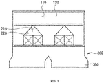
FIG. 3 is a front view showing the static mixer for mixing exhaust gases according to the present disclosure, wherein a mixing plate part is removed from the static mixer; -
FIG. 4 is a front view showing the static mixer for mixing exhaust gases according to the present disclosure, wherein the mixing plate part is disposed on the static mixer; -
FIG. 5 is a side view showing the static mixer for mixing exhaust gases according to the present disclosure; -
FIG. 6 is a perspective view showing a portion of the mixing plate part of the static mixer for mixing exhaust gases according to the present disclosure; -
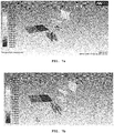
FIGS. 7a and 7b are temperature distribution charts, whereinFIG. 7a shows the mixing plate part having no intermediate flow path andFIG. 7b shows the mixing plate part having an intermediate flow path; -
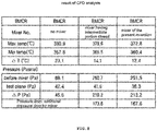
FIG. 8 is a table showing the temperature distribution and pressure loss according to CFD analysis results; -
FIG. 9 is a perspective view showing another example of the mixing plate part in the static mixer for mixing exhaust gases according to the present disclosure; -
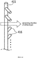
FIG. 10 is a perspective view showing an example of installation angles of nozzles disposed on the mixing plate part ofFIG. 9 ; -
FIG. 11 is a perspective view showing another example of installation angles of nozzles disposed on the mixing plate part ofFIG. 9 ; and -
FIG. 12 is a graph showing the CFD analysis results of the temperature variations in the static mixer having the mixing plate part ofFIG. 9 . - Hereinafter, the present disclosure is disclosed with reference to the attached drawings wherein the corresponding parts in the embodiments of the present disclosure are indicated by corresponding reference numerals and the repeated explanation on the corresponding parts will be avoided. If it is determined that the detailed explanation on the well known technology related to the present disclosure makes the scope of the present disclosure not clear, the explanation will be avoided for the brevity of the description.
- In the description, terms, such as the first, the second, A, B, (a), and (b) may be used to describe various elements, but the elements should not be restricted by the terms. The terms are used to only distinguish one element from the other element. When it is said that one element is described as being "connected" or "coupled" to the other element, one element may be directly connected or coupled to the other element, but it should be understood that another element may be present between the two elements. In contrast, when it is said that one element is described as being "directly connected" or "directly coupled" to the other element, it should be understood that another element is not present between the two elements.
- As shown in
FIGS. 1 to 3 , a static mixer for mixing exhaust gases according to the present disclosure has a structure of a mixing duct for mixing exhaust gases, which is disposed on a selective catalytic reduction device located at the back of a boiler and includes first and secondgas accommodation parts gases gas accommodation parts first inlet 110 and a plurality ofsecond inlets 210 partitioned from each other, and thegases first inlet 110 and the plurality ofsecond inlets 210, are changed in flow paths and flow to a plurality ofsections sections gases first inlet 110 and thesecond inlets 210 to flow alternately. - The plurality of
sections gas accommodation parts discharge part 300 in which thegases FIGS. 4 and5 , amixing plate part 400 is disposed on the upper andlower portions discharge part 300 in such a manner as to form an open region on thecenter portion 330 of the hollow portion thereof and includes a plurality ofunit plates 410 having a given angle (a predetermined angle) with respect to the direction of the exhaust gases discharged. - In more detail, the first
gas accommodation part 100 includes thefirst inlet 110 formed on the top thereof and afirst slant surface 120 having a given angle, and the secondgas accommodation part 200 includes thesecond inlets 210 separated from thefirst inlet 110 to form separate flow paths andsecond slant surfaces 220 having a given angle. Thefirst slant surface 120 and thesecond slant surfaces 220 serve to induce the flows of exhaust gases to thedischarge part 300. - In this case, the
gases gas accommodation parts first inlet 110 and the plurality ofsecond inlets 210, have different temperatures and particle densities from each other. - For example, if the
gas 10 accommodated in the firstgas accommodation part 100 has a high temperature, thegas 20 accommodated in the secondgas accommodation part 200 has a lower temperature than thegas 10. Of course, thegas 10 may have a lower temperature than thegas 20. - According to the present disclosure, the second
gas accommodation part 200 is closer to thedischarge part 300 than the firstgas accommodation part 100 with respect to the flows of exhaust gases. At this time, thesecond inlets 210 are formed independently of each other, while not communicating with each other, but they communicate with thedischarge part 300. Accordingly, thegases first inlet 110 and thesecond inlets 210 can be alternately discharged. - Further, the
discharge part 300 includes a plurality ofbranched ducts 350 communicating with the hollow portion coupled to themixing plate part 400 in such a manner as to be arranged in the directions of the exhaust gases discharged. - As shown in
FIG. 6 , themixing plate part 400 includes: a plurality of one pair ofsupport pipes 415 having one end coupled to the inner bottom surface of the hollow portion of thedischarge part 300 and the other end coupled to the inner top surface of the hollow portion of thedischarge part 300; and a plurality ofunit plates support pipes 415. - So as to allow the
center portion 330 as the intermediate region in the width direction of thedischarge part 300 to be empty, in this case, the unit plates includelower unit plates 411 for blocking a portion of the lower flow path formed by the hollow portion andupper unit plates 412 for blocking a portion of the upper flow path formed by the hollow portion. Further, the unit plates includelower unit plates 411a disposed on the outer corners of thedischarge part 300, not together with theupper unit plates 412. - According to the present disclosure, SCH (Schedule) pipes are applied to the ends of the
unit plates center portion 330 of thedischarge part 300. - In this case, as shown in
FIG. 6 , thelower unit plates 411 are disposed traversely with a given angle with respect to the directions of the flows of exhaust gases discharged through thedischarge part 300, and theupper unit plates 412 are disposed crossedly with a given angle with respect to thelower unit plates 411. - Accordingly, the
lower unit plates 411 and theupper unit plates 412 traverse the flows of exhaust gases, and the gases passing through thelower unit plates 411 and theupper unit plates 412 cross each other, so that mixing between thegases gases mixing plate part 400. - As mentioned above, there is a strict condition that a temperature difference between a high temperature gas and a low temperature gas on the entrance of the SCR device located at the back of the boiler should be 20°C or above or below to the maximum. According to the present disclosure, the exhaust gases having different temperatures are effectively mixed through the
lower unit plates 411 and theupper unit plates 412 crossing each other, so that the temperature distribution on the entrance of the SCR device can be more uniform than that in the conventional practice. - According to the present disclosure, furthermore, the
center portion 330 of thedischarge part 300, which is located between thelower unit plates 411 and theupper unit plates 412, is empty. In this case, if complicated flows like vortexes occur through thelower unit plates 411 and theupper unit plates 412 crossing each other, the mixing efficiency is improved, but the pressure loss is increased. Through theempty center portion 330, accordingly, the problem of the pressure loss can be solved. Through theempty center portion 330, further, the flows of exhaust gases are kept to thecenter portion 330 so that the directions of flows of exhaust gases through thelower unit plates 411, thecenter portion 330, and theupper unit plates 412 are different from each other to induce more effective mixing. - The static mixer according to the present disclosure has the structure wherein the
lower unit plates 411 and theupper unit plates 412 cross each other to improve the mixing efficiency through the turbulent flows and the structure wherein thelower unit plates 411 and theupper unit plates 412 block portions of the lower and upper flow paths of the hollow portion of thedischarge part 300 to reduce the pressure loss and material costs and to improve the mixing efficiency through the complicated flows. - According to the present disclosure, three
upper unit plates 412 are disposed on eachbranched duct 350, and threelower unit plates 411 pair with the threeupper unit plates 412 in such a manner as to cross with the threeupper unit plates 412. Further, thelower unit plate 411a is spaced apart from theupper unit plate 412 on the outer corner of each branchedduct 350. - According to the CFD analysis, as shown in
FIG. 7 , the static mixer having the above-mentioned configuration allows the high temperature gas and the lower temperature gas to cross each other through the mixingplate part 400 and at the same time allows thecenter portion 330 of thedischarge part 300 to be empty, so that vortexes are generated to permit the temperatures to be uniformly distributed. - Through the results of the CFD analysis, accordingly, the effects listed in the table of
FIG. 8 can be checked. - According to the results of the CFD analysis, a deviation between the maximum temperature and the minimum temperature is 23.1°C in a general duct structure where no static mixer is disposed.
- On the other hand, a deviation between the maximum temperature and the minimum temperature is 14.1°C in a structure where a static mixer is disposed but the
upper unit plates 412 and thelower unit plates 411 cross each other in such a manner as to block the entire flow path of the hollow portion of thedischarge 300, while not having any empty space on thecenter portion 330 of the flow path of the hollow portion of thedischarge 300. Through the above results, it can be checked that the formation of the mixingplate part 400 enables the temperature distribution to be uniformly generated. - Lastly, a deviation between the maximum temperature and the minimum temperature is 12.4°C in a structure where the static mixer of the present disclosure is provided with three flow path regions divided by the
lower unit plates 411, thecenter portion 330, and theupper unit plates 412, and in this structure, the smallest deviation can be obtained. - According to the results of the pressure drops for the respective structures, a pressure loss is 45.6 pa in the general duct structure where no static mixer is disposed, which is the smallest value, but the deviation between the maximum temperature and the minimum temperature is 23.1°C, so that the structure does not satisfy the temperature condition on the entrance of the SCR device and accordingly, it is not usable as the equipment at the back of the boiler.
- Contrarily, a pressure loss is 173.6 pa in the structure where the static mixer according to the present disclosure is disposed to allow the
upper unit plates 412 and thelower unit plates 411 to cross each other in such a manner as to block the entire flow path of the hollow portion of thedischarge 300, and a pressure loss is 167.6 pa in the structure where the static mixer according to the present disclosure is disposed to allow thecenter portion 330 of thedischarge 300 to be open, which is more reduced than that in the structure where theupper unit plates 412 and thelower unit plates 411 cross each other, while having noempty center portion 330. - Especially, it should be noted that the structure where the static mixer allows the
center portion 330 of thedischarge 300 to be open can have more reduced pressure drop and more uniform temperature distribution than the structure where the static mixer allows theupper unit plates 412 and thelower unit plates 411 cross each other, while having noempty center portion 330. Accordingly, the structure wherein the flow path of the hollow portion of thedischarge part 300 is divided into three regions of thelower unit plates 411, thecenter portion 330, and theupper unit plates 412 becomes the most excellent structure in consideration of the temperature condition on the entrance of the SCR device. - On the other hand, another example of the mixing
plate part 400 having nozzles will be explained with reference toFIGS. 9 to 11 . - As shown in
FIG. 9 , the mixingplate part 400 includes: a plurality of pairs ofsupport pipes 415 having one end coupled to the inner bottom surface of the hollow portion of thedischarge part 300 and the other end coupled to the inner top surface of the hollow portion of thedischarge part 300; and a plurality ofunit plates 410 whose both ends are coupled to the pairs ofsupport pipes 415. - At this time, each
support pipe 415 is hollow in the interior thereof and has aconnection pipe 417 whose one end connected to one side of the top or underside end thereof, the other end of theconnection pipe 417 communicating with the first and secondgas accommodation parts gas accommodation parts connection pipes 417 and introduced directly into thesupport pipes 415. - Further, each
support pipe 415 has at least one ormore nozzles 416 disposed on the outer peripheral surface thereof in a longitudinal direction thereof, and if thenozzles 416 are disposed, as shown inFIGS. 10 and11 , they are located with given angles in up and down or left and right directions with respect to the advancing directions of the exhaust gases flowing to the sides of thesupport pipes 415. - Accordingly, the exhaust gases having the given angles in the up and down or left and right directions with respect to the exhaust gases flowing to the sides of the
support pipes 415 are secondarily discharged from thenozzles 416, thereby generating more complicated turbulent flows to improve the mixing efficiency. As a result, the temperature distribution of thegases -
FIG. 12 is a graph showing the CFD analysis results of the temperature variations in the static mixer having the mixing plate part ofFIG. 9 . - According to the results of the CFD analysis, as shown in
FIG. 12 , it is checked that thegases - Accordingly, if the
nozzles 416 are disposed on thesupport pipes 415 to secondarily discharge the exhaust gases, and further, if the installation angles or lengths of thenozzles 416 are appropriately adjusted, the mixing effects of the exhaust gases can be more excellent than those in the conventional practice. - As set forth in the foregoing, the static mixer for mixing exhaust gases according to the present disclosure is configured wherein the upper unit plates and the lower unit plates crossing each other are located on the region of the discharge part to generate complicated flows like vortexes, thereby improving the mixing efficiency, so that it is possible to satisfy the strict condition that a temperature distributed on the section of the duct on the entrance of the SCR device should be 20°C or above or below to the maximum.
- Further, the static mixer for mixing exhaust gases according to the present disclosure is configured wherein the open intermediate flow path is formed between the upper unit plates and the lower unit plates, thereby achieving more reduced pressure loss than the static mixer having the intermediate flow path portion not open and further reducing the number of unit plates to save the manufacturing cost thereof.
- Additionally, the static mixer for mixing exhaust gases according to the present disclosure is configured wherein the nozzles are disposed on the support pipes supporting the upper unit plates and the lower unit plates to discharge portion of exhaust gases, thereby more improving the mixing efficiency of the exhaust gases.
- While the present disclosure has been described with reference to the particular illustrative embodiments, it is not to be restricted by the embodiments but only by the appended claims. It is to be appreciated that those skilled in the art can change or modify the embodiments without departing from the scope and spirit of the present disclosure.
Claims (15)
- A static mixer for mixing exhaust gases (10, 20) to be supplied to a selective catalytic reduction device located at the back of a boiler, the static mixer comprising:a gas accommodation part (100, 200) having a first inlet (110) and a plurality of second inlets (210) partitioned from each other to introduce gases (10, 20) having different temperatures thereinto so that the gases (10, 20) introduced through the first inlet (110) and the plurality of second inlets (210) flow to a plurality of divided sections (111, 211);a discharge part (300) communicating with the gas accommodation part (100, 200) to collect and discharge the gases (10, 20), the discharge part (300) including a hollow portion (310, 320, 330); anda mixing plate part (400) having a plurality of unit plates (411, 412) disposed on the upper and lower portions of the hollow portion (310, 320) of the discharge part (300) in such a manner as to have a predetermined angle with respect to flow directions of the exhaust gases (10, 20) discharged.
- The static mixer according to claim 1, wherein the gas accommodation part (100, 200) comprises:a first gas accommodation part (100) having the first inlet (110) formed on the top thereof and configured to introduce gases (10, 20) into the static mixer; anda second gas accommodation part (200) having the plurality of second inlets (210) separated from the first inlet (110) to form separate flow paths for gases (10, 20) being introduced into the static mixer.
- The static mixer according to claim 2, wherein the second gas accommodation part (200) is closer to the discharge part (300) than the first gas accommodation part (100) with respect to the flows of the exhaust gases (10, 20).
- The static mixer according to claim 3, wherein the plurality of second inlets (210) are formed independently of each other, so that the gases (10, 20) having different temperatures introduced from the first inlet (110) and the plurality of second inlets (210) are alternately discharged through the discharge part (300).
- The static mixer according to claim 1, wherein the discharge part (300) comprises a plurality of branched ducts (350) extending from the hollow portion (310, 320, 330) coupled to the mixing plate part (400) in such a manner as to be arranged in the directions of the exhaust gases (10, 20) discharged.
- The static mixer according to claim 1, wherein the mixing plate part (400) comprises:a plurality of pairs of support pipes (415) having one end coupled to an inner bottom surface of the hollow portion of the discharge part (300) and the other end coupled to an inner top surface of the hollow portion of the discharge part (300) ; andthe plurality of unit plates (411, 412) having opposing ends coupled to the plurality of pairs of support pipes (415).
- The static mixer according to claim 6, wherein the plurality of unit plates (411, 412) comprises:lower unit plates (411) for blocking a portion of a lower flow path formed by the hollow portion (320) of the discharge part(300); andupper unit plates (412) for blocking a portion of an upper flow path formed by the hollow portion (310) of the discharge part (300).
- The static mixer according to claim 7, wherein the lower unit plates (411) are disposed traversely with a predetermined angle with respect to the directions of the flows of exhaust gases (10, 20) discharged through the discharge part (300).
- The static mixer according to claim 8, wherein the upper unit plates (412) are disposed crossedly with a given angle with respect to the lower unit plates (411).
- The static mixer according to claim 5, wherein each of the branched ducts (350) of the discharge part (300) comprises:three upper unit plates (412);three lower unit plates (411) pairing with the three upper unit plates (412) in such a manner as to cross the three upper unit plates (412); andone lower unit plate (411a) spaced apart from the upper unit plate (412) on an outer corner thereof.
- The static mixer according to claim 2, wherein the gases (10, 20) accommodated in the first gas accommodation part (100) and the second gas accommodation part (200) have different temperatures from each other.
- The static mixer according to claim 6, wherein each support pipe (415) of the plurality of support pipes comprises:a connection pipe (417) connected thereto to supply exhaust gas (10, 20) to an interior of the support pipe; andat least one or more nozzles (416) disposed on an outer peripheral surface of the support pipe to discharge the exhaust gas (10, 20) supplied to the interior thereof.
- The static mixer according to claim 12, wherein the at least one or more nozzles (416) are disposed in a longitudinal direction of the support pipe (415).
- The static mixer according to claim 13, wherein the at least one or more nozzles (416) are disposed with predetermined angles in up and down or left and right directions with respect to the advancing directions of the exhaust gases (10, 20).
- A static mixer for mixing exhaust gases (10, 20) having different temperatures, comprising:a first gas accommodation part (100) having a first inlet (110) for receiving a first exhaust gas (10);a second gas accommodation part (200) having a plurality of second inlets (210) partitioned from each other for receiving a second exhaust gas (20) having a temperature different from a temperature of the first exhaust gas (10);a discharge part (300) communicating with the first and second gas accommodation parts (100, 200) to receive the first and second exhaust gases (10, 20) having different temperatures and to discharge the first and second gases (10, 20) after mixing, the discharge part (300) including a hollow portion (310, 320, 330);a mixing plate part (400) having lower unit plates (411) disposed on lower portions of the hollow portion (320) of the discharge part (300), the lower unit plates (411) being traversedly angled with respect to flow directions of the exhaust gases (10, 20), the lower unit plates (411) configured to block a portion of a lower flow path formed by the hollow portion of the discharge part (300); andthe mixing plate part (400) having upper unit plates (412) disposed on upper portions of the hollow portion (310) of the discharge part (300), the upper unit plates (412) being crossedly angled so as to cross the flow directions of the exhaust gases (10, 20), the upper unit plates (412) configured to block a portion of an upper flow path formed by the hollow portion of the discharge part (300); andan open region is formed between the upper and lower unit plates (411, 412) so as to provide an unblocked center flow path between the upper and lower flow paths in the hollow portion.
Applications Claiming Priority (2)
| Application Number | Priority Date | Filing Date | Title |
|---|---|---|---|
| KR1020150159231A KR101778763B1 (en) | 2015-11-12 | 2015-11-12 | static mixer |
| KR1020150164820A KR101679055B1 (en) | 2015-11-24 | 2015-11-24 | An exhaust gas mixer includes a nozzle |
Publications (2)
| Publication Number | Publication Date |
|---|---|
| EP3167954A1 true EP3167954A1 (en) | 2017-05-17 |
| EP3167954B1 EP3167954B1 (en) | 2019-03-27 |
Family
ID=57345701
Family Applications (1)
| Application Number | Title | Priority Date | Filing Date |
|---|---|---|---|
| EP16198408.3A Active EP3167954B1 (en) | 2015-11-12 | 2016-11-11 | Static mixer |
Country Status (2)
| Country | Link |
|---|---|
| US (1) | US10137421B2 (en) |
| EP (1) | EP3167954B1 (en) |
Families Citing this family (3)
| Publication number | Priority date | Publication date | Assignee | Title |
|---|---|---|---|---|
| EP3167954B1 (en) * | 2015-11-12 | 2019-03-27 | Doosan Heavy Industries & Construction Co., Ltd. | Static mixer |
| JP7182956B2 (en) * | 2018-08-31 | 2022-12-05 | 三菱重工業株式会社 | Exhaust gas purifier |
| CN111346508A (en) * | 2020-04-10 | 2020-06-30 | 西安西热锅炉环保工程有限公司 | A kind of flue partition mixer and method |
Citations (3)
| Publication number | Priority date | Publication date | Assignee | Title |
|---|---|---|---|---|
| EP2320142A1 (en) * | 2008-08-25 | 2011-05-11 | Babcock-Hitachi Kabushiki Kaisha | Flue gas denitration device |
| EP2620208A1 (en) * | 2012-01-25 | 2013-07-31 | Alstom Technology Ltd | Gas mixing arrangement |
| WO2014039039A1 (en) * | 2012-09-06 | 2014-03-13 | Hideo Miyanishi | Combustion gas cooling apparatus, denitration apparatus having the combustion gas cooling apparatus, and combustion gas cooling method |
Family Cites Families (36)
| Publication number | Priority date | Publication date | Assignee | Title |
|---|---|---|---|---|
| US4054418A (en) * | 1975-11-10 | 1977-10-18 | E. I. Du Pont De Nemours And Company | Catalytic abatement system |
| US4050903A (en) * | 1976-10-29 | 1977-09-27 | Uop Inc. | Combination muffler and catalytic converter |
| CA1096630A (en) * | 1978-05-26 | 1981-03-03 | David J. Tookey | Static mixer |
| NL8602338A (en) * | 1986-09-16 | 1988-04-18 | Hoogovens Groep Bv | GAS MIXER. |
| JPH07217859A (en) | 1994-01-28 | 1995-08-18 | Mitsubishi Heavy Ind Ltd | Exhaust gas duct for boiler |
| JP3373771B2 (en) | 1997-10-08 | 2003-02-04 | 株式会社東芝 | Waste heat recovery boiler |
| KR19990036949U (en) | 1999-05-10 | 1999-10-05 | 이상국 | Parking System |
| DE19934413A1 (en) | 1999-07-22 | 2001-01-25 | Siemens Ag | Apparatus for introducing an additive into an exhaust gas in the exhaust gas line of a diesel engine comprises a nozzle and mixers which are combined to form a constructive and functional component |
| ATE381381T1 (en) * | 2003-11-20 | 2008-01-15 | Eftec Europe Holding Ag | STATIC MIXING DEVICE, DISCHARGE DEVICE AND STORAGE CONTAINER WITH SUCH A MIXING DEVICE. USE OF SUCH A MIXING DEVICE AND METHOD FOR DISCHARGING |
| US7581387B2 (en) * | 2005-02-28 | 2009-09-01 | Caterpillar Inc. | Exhaust gas mixing system |
| KR20050033605A (en) | 2005-03-21 | 2005-04-12 | 심주섭 | Gas exhausting device of exhaust pipe for boiler |
| DE202008001547U1 (en) * | 2007-07-24 | 2008-04-10 | Emcon Technologies Germany (Augsburg) Gmbh | Assembly for introducing a reducing agent into the exhaust pipe of an exhaust system of an internal combustion engine |
| DE102007048558A1 (en) * | 2007-10-09 | 2009-04-16 | Audi Ag | Static mixer for an exhaust system of an internal combustion engine-driven vehicle, in particular of a motor vehicle |
| US8591848B2 (en) | 2007-11-09 | 2013-11-26 | Fuel Tech, Inc. | Selective catalytic NOx reduction process and control system |
| US9095827B2 (en) * | 2008-04-21 | 2015-08-04 | Tenneco Automotive Operating Company Inc. | Exhaust gas flow mixer |
| JP2010144569A (en) | 2008-12-17 | 2010-07-01 | Fuji Heavy Ind Ltd | Selective reduction catalyst device |
| US8741239B2 (en) | 2009-02-25 | 2014-06-03 | General Electric Company | Method and apparatus for operation of CO/VOC oxidation catalyst to reduce NO2 formation for gas turbine |
| JP5316796B2 (en) | 2009-08-04 | 2013-10-16 | 三菱ふそうトラック・バス株式会社 | Engine exhaust purification system |
| US8375709B2 (en) * | 2009-11-17 | 2013-02-19 | Tenneco Automotive Operating Company Inc. | Exhaust gas additive/treatment system and mixer for use therein |
| US8359832B2 (en) * | 2009-12-21 | 2013-01-29 | Caterpillar Inc. | SCR reductant mixer |
| KR101664494B1 (en) | 2010-07-08 | 2016-10-13 | 두산인프라코어 주식회사 | Static mixer for mixing urea aqueous solution and engine exhaust gas |
| KR101159599B1 (en) | 2010-07-29 | 2012-06-27 | 현대제철 주식회사 | Mixing chamber for electric furnance |
| JP2013087745A (en) | 2011-10-21 | 2013-05-13 | Toyota Industries Corp | Reducing agent supply device and exhaust gas purifying apparatus including the same |
| DE102011086321B4 (en) * | 2011-11-14 | 2013-07-25 | Mtu Friedrichshafen Gmbh | Gas mixer and gas mixing system |
| MY185231A (en) * | 2012-03-02 | 2021-04-30 | Continental Automotive Gmbh | Device for exhaust purification |
| KR101409584B1 (en) | 2013-03-14 | 2014-06-20 | 한국서부발전 주식회사 | Flue gas denitrogenization equipment having device for preventing drift of boiler |
| US9217353B2 (en) * | 2013-04-03 | 2015-12-22 | Caterpillar Inc. | Mixer for fluid injection system |
| US20150040547A1 (en) * | 2013-08-08 | 2015-02-12 | Tenneco Automotive Operating Company Inc. | Mirrored Two-Stage Mixer |
| JP2015075015A (en) | 2013-10-08 | 2015-04-20 | ダイムラー・アクチェンゲゼルシャフトDaimler AG | Casing structure for exhaust emission control device |
| JP6539353B2 (en) * | 2015-03-16 | 2019-07-03 | ワット・フューエル・セル・コーポレイションWatt Fuel Cell Corp. | Centrifugal blower system with internal gas mixing function and gas phase chemical reactor incorporating the system |
| US9534525B2 (en) * | 2015-05-27 | 2017-01-03 | Tenneco Automotive Operating Company Inc. | Mixer assembly for exhaust aftertreatment system |
| DE102015108655B4 (en) * | 2015-06-01 | 2017-07-13 | Tenneco Gmbh | mixer |
| US20160032810A1 (en) * | 2015-10-16 | 2016-02-04 | Caterpillar Inc. | Mixer for exhaust gas aftertreatment system |
| US10058829B2 (en) * | 2015-10-21 | 2018-08-28 | Jason Ladd | Static mixer manifold |
| EP3167954B1 (en) * | 2015-11-12 | 2019-03-27 | Doosan Heavy Industries & Construction Co., Ltd. | Static mixer |
| US9909478B2 (en) * | 2016-05-02 | 2018-03-06 | Caterpillar Inc. | Mixer for exhaust aftertreatment systems |
-
2016
- 2016-11-11 EP EP16198408.3A patent/EP3167954B1/en active Active
- 2016-11-11 US US15/349,163 patent/US10137421B2/en active Active
Patent Citations (3)
| Publication number | Priority date | Publication date | Assignee | Title |
|---|---|---|---|---|
| EP2320142A1 (en) * | 2008-08-25 | 2011-05-11 | Babcock-Hitachi Kabushiki Kaisha | Flue gas denitration device |
| EP2620208A1 (en) * | 2012-01-25 | 2013-07-31 | Alstom Technology Ltd | Gas mixing arrangement |
| WO2014039039A1 (en) * | 2012-09-06 | 2014-03-13 | Hideo Miyanishi | Combustion gas cooling apparatus, denitration apparatus having the combustion gas cooling apparatus, and combustion gas cooling method |
Also Published As
| Publication number | Publication date |
|---|---|
| EP3167954B1 (en) | 2019-03-27 |
| US20170136425A1 (en) | 2017-05-18 |
| US10137421B2 (en) | 2018-11-27 |
Similar Documents
| Publication | Publication Date | Title |
|---|---|---|
| CN100479908C (en) | Mixer and mixing method | |
| CN103759474B (en) | Plate heat exchanger | |
| EP2889570B1 (en) | Heat exchanger | |
| US5330267A (en) | Stationary fluid mixer with fluid guide surfaces | |
| US4646822A (en) | Heat exchanger | |
| KR102017485B1 (en) | Flue gas mixing apparatus | |
| US10137421B2 (en) | Static mixer | |
| KR101667503B1 (en) | Large-size Circulating Fluidized Bed Boiler, Air Distributor and Air Distributor Assembly | |
| SE533440C2 (en) | Induction apparatus for combining air flows | |
| TW201736797A (en) | Cavity x mixer heat exchanger | |
| CN104520549A (en) | Method for mixing exhaust streams | |
| EP2353704B1 (en) | Apparatus and method for mixing two gas streams | |
| JP2009243644A (en) | Flow distributor and flow distribution system | |
| US20160025413A1 (en) | Pipe bundle recuperator on a sintering furnace and thermal transfer method having a sintering furnace and having a pipe bundle recuperator | |
| KR20180138348A (en) | Exhaust gas flow splitter and boiler exhaust apparatus having the same | |
| US10401048B2 (en) | Air flow mixer | |
| CN100334653C (en) | positioning shelf | |
| US9550165B2 (en) | Catalytic reactor | |
| KR102096435B1 (en) | Impinging type temperature uniformity device | |
| FI121638B (en) | Fluidized bed reactor | |
| EA036541B1 (en) | Pipe connection piece | |
| JP2005300072A (en) | Evaporator | |
| JP2005147426A (en) | Heat exchanger | |
| KR101679055B1 (en) | An exhaust gas mixer includes a nozzle | |
| KR101778763B1 (en) | static mixer |
Legal Events
| Date | Code | Title | Description |
|---|---|---|---|
| PUAI | Public reference made under article 153(3) epc to a published international application that has entered the european phase |
Free format text: ORIGINAL CODE: 0009012 |
|
| STAA | Information on the status of an ep patent application or granted ep patent |
Free format text: STATUS: REQUEST FOR EXAMINATION WAS MADE |
|
| 17P | Request for examination filed |
Effective date: 20161111 |
|
| AK | Designated contracting states |
Kind code of ref document: A1 Designated state(s): AL AT BE BG CH CY CZ DE DK EE ES FI FR GB GR HR HU IE IS IT LI LT LU LV MC MK MT NL NO PL PT RO RS SE SI SK SM TR |
|
| AX | Request for extension of the european patent |
Extension state: BA ME |
|
| RBV | Designated contracting states (corrected) |
Designated state(s): AL AT BE BG CH CY CZ DE DK EE ES FI FR GB GR HR HU IE IS IT LI LT LU LV MC MK MT NL NO PL PT RO RS SE SI SK SM TR |
|
| STAA | Information on the status of an ep patent application or granted ep patent |
Free format text: STATUS: EXAMINATION IS IN PROGRESS |
|
| 17Q | First examination report despatched |
Effective date: 20180206 |
|
| GRAP | Despatch of communication of intention to grant a patent |
Free format text: ORIGINAL CODE: EPIDOSNIGR1 |
|
| STAA | Information on the status of an ep patent application or granted ep patent |
Free format text: STATUS: GRANT OF PATENT IS INTENDED |
|
| INTG | Intention to grant announced |
Effective date: 20181115 |
|
| GRAS | Grant fee paid |
Free format text: ORIGINAL CODE: EPIDOSNIGR3 |
|
| GRAA | (expected) grant |
Free format text: ORIGINAL CODE: 0009210 |
|
| STAA | Information on the status of an ep patent application or granted ep patent |
Free format text: STATUS: THE PATENT HAS BEEN GRANTED |
|
| AK | Designated contracting states |
Kind code of ref document: B1 Designated state(s): AL AT BE BG CH CY CZ DE DK EE ES FI FR GB GR HR HU IE IS IT LI LT LU LV MC MK MT NL NO PL PT RO RS SE SI SK SM TR |
|
| REG | Reference to a national code |
Ref country code: GB Ref legal event code: FG4D |
|
| REG | Reference to a national code |
Ref country code: CH Ref legal event code: EP |
|
| REG | Reference to a national code |
Ref country code: AT Ref legal event code: REF Ref document number: 1112376 Country of ref document: AT Kind code of ref document: T Effective date: 20190415 |
|
| REG | Reference to a national code |
Ref country code: IE Ref legal event code: FG4D |
|
| REG | Reference to a national code |
Ref country code: DE Ref legal event code: R096 Ref document number: 602016011519 Country of ref document: DE |
|
| PG25 | Lapsed in a contracting state [announced via postgrant information from national office to epo] |
Ref country code: SE Free format text: LAPSE BECAUSE OF FAILURE TO SUBMIT A TRANSLATION OF THE DESCRIPTION OR TO PAY THE FEE WITHIN THE PRESCRIBED TIME-LIMIT Effective date: 20190327 Ref country code: LT Free format text: LAPSE BECAUSE OF FAILURE TO SUBMIT A TRANSLATION OF THE DESCRIPTION OR TO PAY THE FEE WITHIN THE PRESCRIBED TIME-LIMIT Effective date: 20190327 Ref country code: NO Free format text: LAPSE BECAUSE OF FAILURE TO SUBMIT A TRANSLATION OF THE DESCRIPTION OR TO PAY THE FEE WITHIN THE PRESCRIBED TIME-LIMIT Effective date: 20190627 Ref country code: FI Free format text: LAPSE BECAUSE OF FAILURE TO SUBMIT A TRANSLATION OF THE DESCRIPTION OR TO PAY THE FEE WITHIN THE PRESCRIBED TIME-LIMIT Effective date: 20190327 |
|
| REG | Reference to a national code |
Ref country code: NL Ref legal event code: MP Effective date: 20190327 |
|
| PG25 | Lapsed in a contracting state [announced via postgrant information from national office to epo] |
Ref country code: BG Free format text: LAPSE BECAUSE OF FAILURE TO SUBMIT A TRANSLATION OF THE DESCRIPTION OR TO PAY THE FEE WITHIN THE PRESCRIBED TIME-LIMIT Effective date: 20190627 Ref country code: NL Free format text: LAPSE BECAUSE OF FAILURE TO SUBMIT A TRANSLATION OF THE DESCRIPTION OR TO PAY THE FEE WITHIN THE PRESCRIBED TIME-LIMIT Effective date: 20190327 Ref country code: LV Free format text: LAPSE BECAUSE OF FAILURE TO SUBMIT A TRANSLATION OF THE DESCRIPTION OR TO PAY THE FEE WITHIN THE PRESCRIBED TIME-LIMIT Effective date: 20190327 Ref country code: RS Free format text: LAPSE BECAUSE OF FAILURE TO SUBMIT A TRANSLATION OF THE DESCRIPTION OR TO PAY THE FEE WITHIN THE PRESCRIBED TIME-LIMIT Effective date: 20190327 Ref country code: GR Free format text: LAPSE BECAUSE OF FAILURE TO SUBMIT A TRANSLATION OF THE DESCRIPTION OR TO PAY THE FEE WITHIN THE PRESCRIBED TIME-LIMIT Effective date: 20190628 Ref country code: HR Free format text: LAPSE BECAUSE OF FAILURE TO SUBMIT A TRANSLATION OF THE DESCRIPTION OR TO PAY THE FEE WITHIN THE PRESCRIBED TIME-LIMIT Effective date: 20190327 |
|
| REG | Reference to a national code |
Ref country code: AT Ref legal event code: MK05 Ref document number: 1112376 Country of ref document: AT Kind code of ref document: T Effective date: 20190327 |
|
| PG25 | Lapsed in a contracting state [announced via postgrant information from national office to epo] |
Ref country code: IT Free format text: LAPSE BECAUSE OF FAILURE TO SUBMIT A TRANSLATION OF THE DESCRIPTION OR TO PAY THE FEE WITHIN THE PRESCRIBED TIME-LIMIT Effective date: 20190327 Ref country code: PT Free format text: LAPSE BECAUSE OF FAILURE TO SUBMIT A TRANSLATION OF THE DESCRIPTION OR TO PAY THE FEE WITHIN THE PRESCRIBED TIME-LIMIT Effective date: 20190727 Ref country code: SK Free format text: LAPSE BECAUSE OF FAILURE TO SUBMIT A TRANSLATION OF THE DESCRIPTION OR TO PAY THE FEE WITHIN THE PRESCRIBED TIME-LIMIT Effective date: 20190327 Ref country code: AL Free format text: LAPSE BECAUSE OF FAILURE TO SUBMIT A TRANSLATION OF THE DESCRIPTION OR TO PAY THE FEE WITHIN THE PRESCRIBED TIME-LIMIT Effective date: 20190327 Ref country code: EE Free format text: LAPSE BECAUSE OF FAILURE TO SUBMIT A TRANSLATION OF THE DESCRIPTION OR TO PAY THE FEE WITHIN THE PRESCRIBED TIME-LIMIT Effective date: 20190327 Ref country code: ES Free format text: LAPSE BECAUSE OF FAILURE TO SUBMIT A TRANSLATION OF THE DESCRIPTION OR TO PAY THE FEE WITHIN THE PRESCRIBED TIME-LIMIT Effective date: 20190327 Ref country code: RO Free format text: LAPSE BECAUSE OF FAILURE TO SUBMIT A TRANSLATION OF THE DESCRIPTION OR TO PAY THE FEE WITHIN THE PRESCRIBED TIME-LIMIT Effective date: 20190327 Ref country code: CZ Free format text: LAPSE BECAUSE OF FAILURE TO SUBMIT A TRANSLATION OF THE DESCRIPTION OR TO PAY THE FEE WITHIN THE PRESCRIBED TIME-LIMIT Effective date: 20190327 |
|
| PG25 | Lapsed in a contracting state [announced via postgrant information from national office to epo] |
Ref country code: SM Free format text: LAPSE BECAUSE OF FAILURE TO SUBMIT A TRANSLATION OF THE DESCRIPTION OR TO PAY THE FEE WITHIN THE PRESCRIBED TIME-LIMIT Effective date: 20190327 Ref country code: PL Free format text: LAPSE BECAUSE OF FAILURE TO SUBMIT A TRANSLATION OF THE DESCRIPTION OR TO PAY THE FEE WITHIN THE PRESCRIBED TIME-LIMIT Effective date: 20190327 |
|
| PG25 | Lapsed in a contracting state [announced via postgrant information from national office to epo] |
Ref country code: IS Free format text: LAPSE BECAUSE OF FAILURE TO SUBMIT A TRANSLATION OF THE DESCRIPTION OR TO PAY THE FEE WITHIN THE PRESCRIBED TIME-LIMIT Effective date: 20190727 Ref country code: AT Free format text: LAPSE BECAUSE OF FAILURE TO SUBMIT A TRANSLATION OF THE DESCRIPTION OR TO PAY THE FEE WITHIN THE PRESCRIBED TIME-LIMIT Effective date: 20190327 |
|
| REG | Reference to a national code |
Ref country code: DE Ref legal event code: R097 Ref document number: 602016011519 Country of ref document: DE |
|
| PG25 | Lapsed in a contracting state [announced via postgrant information from national office to epo] |
Ref country code: DK Free format text: LAPSE BECAUSE OF FAILURE TO SUBMIT A TRANSLATION OF THE DESCRIPTION OR TO PAY THE FEE WITHIN THE PRESCRIBED TIME-LIMIT Effective date: 20190327 |
|
| PLBE | No opposition filed within time limit |
Free format text: ORIGINAL CODE: 0009261 |
|
| STAA | Information on the status of an ep patent application or granted ep patent |
Free format text: STATUS: NO OPPOSITION FILED WITHIN TIME LIMIT |
|
| PG25 | Lapsed in a contracting state [announced via postgrant information from national office to epo] |
Ref country code: SI Free format text: LAPSE BECAUSE OF FAILURE TO SUBMIT A TRANSLATION OF THE DESCRIPTION OR TO PAY THE FEE WITHIN THE PRESCRIBED TIME-LIMIT Effective date: 20190327 |
|
| 26N | No opposition filed |
Effective date: 20200103 |
|
| PG25 | Lapsed in a contracting state [announced via postgrant information from national office to epo] |
Ref country code: TR Free format text: LAPSE BECAUSE OF FAILURE TO SUBMIT A TRANSLATION OF THE DESCRIPTION OR TO PAY THE FEE WITHIN THE PRESCRIBED TIME-LIMIT Effective date: 20190327 |
|
| REG | Reference to a national code |
Ref country code: CH Ref legal event code: PL |
|
| PG25 | Lapsed in a contracting state [announced via postgrant information from national office to epo] |
Ref country code: LU Free format text: LAPSE BECAUSE OF NON-PAYMENT OF DUE FEES Effective date: 20191111 Ref country code: MC Free format text: LAPSE BECAUSE OF FAILURE TO SUBMIT A TRANSLATION OF THE DESCRIPTION OR TO PAY THE FEE WITHIN THE PRESCRIBED TIME-LIMIT Effective date: 20190327 Ref country code: CH Free format text: LAPSE BECAUSE OF NON-PAYMENT OF DUE FEES Effective date: 20191130 Ref country code: LI Free format text: LAPSE BECAUSE OF NON-PAYMENT OF DUE FEES Effective date: 20191130 |
|
| REG | Reference to a national code |
Ref country code: BE Ref legal event code: MM Effective date: 20191130 |
|
| PG25 | Lapsed in a contracting state [announced via postgrant information from national office to epo] |
Ref country code: IE Free format text: LAPSE BECAUSE OF NON-PAYMENT OF DUE FEES Effective date: 20191111 |
|
| PG25 | Lapsed in a contracting state [announced via postgrant information from national office to epo] |
Ref country code: BE Free format text: LAPSE BECAUSE OF NON-PAYMENT OF DUE FEES Effective date: 20191130 |
|
| PG25 | Lapsed in a contracting state [announced via postgrant information from national office to epo] |
Ref country code: CY Free format text: LAPSE BECAUSE OF FAILURE TO SUBMIT A TRANSLATION OF THE DESCRIPTION OR TO PAY THE FEE WITHIN THE PRESCRIBED TIME-LIMIT Effective date: 20190327 |
|
| PG25 | Lapsed in a contracting state [announced via postgrant information from national office to epo] |
Ref country code: MT Free format text: LAPSE BECAUSE OF FAILURE TO SUBMIT A TRANSLATION OF THE DESCRIPTION OR TO PAY THE FEE WITHIN THE PRESCRIBED TIME-LIMIT Effective date: 20190327 Ref country code: HU Free format text: LAPSE BECAUSE OF FAILURE TO SUBMIT A TRANSLATION OF THE DESCRIPTION OR TO PAY THE FEE WITHIN THE PRESCRIBED TIME-LIMIT; INVALID AB INITIO Effective date: 20161111 |
|
| REG | Reference to a national code |
Ref country code: DE Ref legal event code: R079 Ref document number: 602016011519 Country of ref document: DE Free format text: PREVIOUS MAIN CLASS: B01F0003020000 Ipc: B01F0023100000 |
|
| PG25 | Lapsed in a contracting state [announced via postgrant information from national office to epo] |
Ref country code: MK Free format text: LAPSE BECAUSE OF FAILURE TO SUBMIT A TRANSLATION OF THE DESCRIPTION OR TO PAY THE FEE WITHIN THE PRESCRIBED TIME-LIMIT Effective date: 20190327 |
|
| PGFP | Annual fee paid to national office [announced via postgrant information from national office to epo] |
Ref country code: GB Payment date: 20250918 Year of fee payment: 10 |
|
| PGFP | Annual fee paid to national office [announced via postgrant information from national office to epo] |
Ref country code: FR Payment date: 20250908 Year of fee payment: 10 |
|
| PGFP | Annual fee paid to national office [announced via postgrant information from national office to epo] |
Ref country code: DE Payment date: 20250916 Year of fee payment: 10 |