EP3167849B1 - Facet prosthetic devices - Google Patents
Facet prosthetic devices Download PDFInfo
- Publication number
- EP3167849B1 EP3167849B1 EP16186386.5A EP16186386A EP3167849B1 EP 3167849 B1 EP3167849 B1 EP 3167849B1 EP 16186386 A EP16186386 A EP 16186386A EP 3167849 B1 EP3167849 B1 EP 3167849B1
- Authority
- EP
- European Patent Office
- Prior art keywords
- facet
- elongated
- endplate
- attachment arm
- stabilizing member
- Prior art date
- Legal status (The legal status is an assumption and is not a legal conclusion. Google has not performed a legal analysis and makes no representation as to the accuracy of the status listed.)
- Not-in-force
Links
Images


Classifications
-
- A—HUMAN NECESSITIES
- A61—MEDICAL OR VETERINARY SCIENCE; HYGIENE
- A61B—DIAGNOSIS; SURGERY; IDENTIFICATION
- A61B17/00—Surgical instruments, devices or methods, e.g. tourniquets
- A61B17/56—Surgical instruments or methods for treatment of bones or joints; Devices specially adapted therefor
- A61B17/58—Surgical instruments or methods for treatment of bones or joints; Devices specially adapted therefor for osteosynthesis, e.g. bone plates, screws, setting implements or the like
- A61B17/68—Internal fixation devices, including fasteners and spinal fixators, even if a part thereof projects from the skin
- A61B17/70—Spinal positioners or stabilisers ; Bone stabilisers comprising fluid filler in an implant
- A61B17/7071—Implants for expanding or repairing the vertebral arch or wedged between laminae or pedicles; Tools therefor
-
- A—HUMAN NECESSITIES
- A61—MEDICAL OR VETERINARY SCIENCE; HYGIENE
- A61F—FILTERS IMPLANTABLE INTO BLOOD VESSELS; PROSTHESES; DEVICES PROVIDING PATENCY TO, OR PREVENTING COLLAPSING OF, TUBULAR STRUCTURES OF THE BODY, e.g. STENTS; ORTHOPAEDIC, NURSING OR CONTRACEPTIVE DEVICES; FOMENTATION; TREATMENT OR PROTECTION OF EYES OR EARS; BANDAGES, DRESSINGS OR ABSORBENT PADS; FIRST-AID KITS
- A61F2/00—Filters implantable into blood vessels; Prostheses, i.e. artificial substitutes or replacements for parts of the body; Appliances for connecting them with the body; Devices providing patency to, or preventing collapsing of, tubular structures of the body, e.g. stents
- A61F2/02—Prostheses implantable into the body
- A61F2/30—Joints
- A61F2/44—Joints for the spine, e.g. vertebrae, spinal discs
- A61F2/4405—Joints for the spine, e.g. vertebrae, spinal discs for apophyseal or facet joints, i.e. between adjacent spinous or transverse processes
-
- A—HUMAN NECESSITIES
- A61—MEDICAL OR VETERINARY SCIENCE; HYGIENE
- A61B—DIAGNOSIS; SURGERY; IDENTIFICATION
- A61B17/00—Surgical instruments, devices or methods, e.g. tourniquets
- A61B17/56—Surgical instruments or methods for treatment of bones or joints; Devices specially adapted therefor
- A61B17/58—Surgical instruments or methods for treatment of bones or joints; Devices specially adapted therefor for osteosynthesis, e.g. bone plates, screws, setting implements or the like
- A61B17/68—Internal fixation devices, including fasteners and spinal fixators, even if a part thereof projects from the skin
- A61B17/70—Spinal positioners or stabilisers ; Bone stabilisers comprising fluid filler in an implant
- A61B17/7062—Devices acting on, attached to, or simulating the effect of, vertebral processes, vertebral facets or ribs ; Tools for such devices
- A61B17/7064—Devices acting on, attached to, or simulating the effect of, vertebral facets; Tools therefor
-
- A—HUMAN NECESSITIES
- A61—MEDICAL OR VETERINARY SCIENCE; HYGIENE
- A61B—DIAGNOSIS; SURGERY; IDENTIFICATION
- A61B17/00—Surgical instruments, devices or methods, e.g. tourniquets
- A61B2017/00831—Material properties
- A61B2017/00867—Material properties shape memory effect
-
- A—HUMAN NECESSITIES
- A61—MEDICAL OR VETERINARY SCIENCE; HYGIENE
- A61F—FILTERS IMPLANTABLE INTO BLOOD VESSELS; PROSTHESES; DEVICES PROVIDING PATENCY TO, OR PREVENTING COLLAPSING OF, TUBULAR STRUCTURES OF THE BODY, e.g. STENTS; ORTHOPAEDIC, NURSING OR CONTRACEPTIVE DEVICES; FOMENTATION; TREATMENT OR PROTECTION OF EYES OR EARS; BANDAGES, DRESSINGS OR ABSORBENT PADS; FIRST-AID KITS
- A61F2/00—Filters implantable into blood vessels; Prostheses, i.e. artificial substitutes or replacements for parts of the body; Appliances for connecting them with the body; Devices providing patency to, or preventing collapsing of, tubular structures of the body, e.g. stents
- A61F2/02—Prostheses implantable into the body
- A61F2/30—Joints
- A61F2/44—Joints for the spine, e.g. vertebrae, spinal discs
- A61F2/442—Intervertebral or spinal discs, e.g. resilient
-
- A—HUMAN NECESSITIES
- A61—MEDICAL OR VETERINARY SCIENCE; HYGIENE
- A61F—FILTERS IMPLANTABLE INTO BLOOD VESSELS; PROSTHESES; DEVICES PROVIDING PATENCY TO, OR PREVENTING COLLAPSING OF, TUBULAR STRUCTURES OF THE BODY, e.g. STENTS; ORTHOPAEDIC, NURSING OR CONTRACEPTIVE DEVICES; FOMENTATION; TREATMENT OR PROTECTION OF EYES OR EARS; BANDAGES, DRESSINGS OR ABSORBENT PADS; FIRST-AID KITS
- A61F2/00—Filters implantable into blood vessels; Prostheses, i.e. artificial substitutes or replacements for parts of the body; Appliances for connecting them with the body; Devices providing patency to, or preventing collapsing of, tubular structures of the body, e.g. stents
- A61F2/02—Prostheses implantable into the body
- A61F2/30—Joints
- A61F2002/30001—Additional features of subject-matter classified in A61F2/28, A61F2/30 and subgroups thereof
- A61F2002/30316—The prosthesis having different structural features at different locations within the same prosthesis; Connections between prosthetic parts; Special structural features of bone or joint prostheses not otherwise provided for
- A61F2002/30535—Special structural features of bone or joint prostheses not otherwise provided for
- A61F2002/30563—Special structural features of bone or joint prostheses not otherwise provided for having elastic means or damping means, different from springs, e.g. including an elastomeric core or shock absorbers
-
- A—HUMAN NECESSITIES
- A61—MEDICAL OR VETERINARY SCIENCE; HYGIENE
- A61F—FILTERS IMPLANTABLE INTO BLOOD VESSELS; PROSTHESES; DEVICES PROVIDING PATENCY TO, OR PREVENTING COLLAPSING OF, TUBULAR STRUCTURES OF THE BODY, e.g. STENTS; ORTHOPAEDIC, NURSING OR CONTRACEPTIVE DEVICES; FOMENTATION; TREATMENT OR PROTECTION OF EYES OR EARS; BANDAGES, DRESSINGS OR ABSORBENT PADS; FIRST-AID KITS
- A61F2/00—Filters implantable into blood vessels; Prostheses, i.e. artificial substitutes or replacements for parts of the body; Appliances for connecting them with the body; Devices providing patency to, or preventing collapsing of, tubular structures of the body, e.g. stents
- A61F2/02—Prostheses implantable into the body
- A61F2/30—Joints
- A61F2002/30001—Additional features of subject-matter classified in A61F2/28, A61F2/30 and subgroups thereof
- A61F2002/30316—The prosthesis having different structural features at different locations within the same prosthesis; Connections between prosthetic parts; Special structural features of bone or joint prostheses not otherwise provided for
- A61F2002/30535—Special structural features of bone or joint prostheses not otherwise provided for
- A61F2002/30576—Special structural features of bone or joint prostheses not otherwise provided for with extending fixation tabs
- A61F2002/30578—Special structural features of bone or joint prostheses not otherwise provided for with extending fixation tabs having apertures, e.g. for receiving fixation screws
-
- A—HUMAN NECESSITIES
- A61—MEDICAL OR VETERINARY SCIENCE; HYGIENE
- A61F—FILTERS IMPLANTABLE INTO BLOOD VESSELS; PROSTHESES; DEVICES PROVIDING PATENCY TO, OR PREVENTING COLLAPSING OF, TUBULAR STRUCTURES OF THE BODY, e.g. STENTS; ORTHOPAEDIC, NURSING OR CONTRACEPTIVE DEVICES; FOMENTATION; TREATMENT OR PROTECTION OF EYES OR EARS; BANDAGES, DRESSINGS OR ABSORBENT PADS; FIRST-AID KITS
- A61F2/00—Filters implantable into blood vessels; Prostheses, i.e. artificial substitutes or replacements for parts of the body; Appliances for connecting them with the body; Devices providing patency to, or preventing collapsing of, tubular structures of the body, e.g. stents
- A61F2/02—Prostheses implantable into the body
- A61F2/30—Joints
- A61F2/44—Joints for the spine, e.g. vertebrae, spinal discs
- A61F2002/4495—Joints for the spine, e.g. vertebrae, spinal discs having a fabric structure, e.g. made from wires or fibres
Definitions
- the spine is comprised of twenty-four vertebrae that are stacked one upon the other to form the spinal column.
- the spine provides strength and support to allow the body to stand and to provide flexibility and motion.
- a Section of each vertebrae includes a passageway that provides passage of the spinal cord through the spinal column. The spine thereby encases and protects the spinal cord.
- the spinal cord also includes thirty-one pairs of nerve roots that branch from either side of the spinal cord, extending through spaces between the vertebrae known as the neural foramen.
- An intervertebral disc is located between each pair of vertebrae.
- the disc is composed of three component structures: (1) the nucleus pulposus; (2) the annulus fibrosus; and (3) the vertebral endplates.
- the disc serves several purposes, including absorbing shock, relieving friction, and handling pressure exerted between the superior and inferior vertebral bodies associated with the disc.
- the disc also relieves stress between the vertebral bodies, which stress would otherwise lead to degeneration or fracture of the vertebral bodies.
- Disorders of the spine comprise some of the costliest and most debilitating health problems facing the populations of the United States and the rest of the world, costing billions of dollars each year. Moreover, as these populations continue to age, the incidence of spinal disorders will continue to grow. Typical disorders include those caused by disease, trauma, genetic disorders, or other causes.
- the state of the art includes a number of treatment options. Medicinal treatments, exercise, and physical therapy are typical conservative treatment options. Less conservative treatment options include surgical intervention, including microdiscectomy, kyphoplasty, laminectomy, dynamic stabilization, disc arthroplasty, and spinal fusion. Traditionally, these treatment options have been applied in isolation, rather than in combination, using the most conservative treatment option that will provide a desired result.
- Panjabi introduced a model of a dynamic spinal stabilization system that describes the interaction between components providing stability in the spine. This model defined spinal instability in terms of a region of laxity around the neutral resting position of a spinal segment, identified as the neutral zone.” Panjabi, M M., "The stabilizing system of the spine. Part 11. Neutral zone and instability hypothesis.” J Spinal Disord 5 (4): 390-397,1992b . There is some evidence that the neutral zone can be increased in cases of intervertebral disc degeneration, spinal injury and spinal fixation. Id . Panjabi has subsequently described dynamic stabilization systems that provide increased mechanical support while the spine is in the neutral zone and decreased support as the spine moves away from the neutral zone. See United States Published Patent Application No. 2004/0236329, published November 25, 2004 .
- WO 2006/055186 A2 published after the priority date of the present invention and therefore at most admissible as prior art under Article 54(3) EPC, discloses a facet joint prosthesis comprising: an elongated upper arm curved forward and configured to attach to an upper vertebral body, an elongated lower attachment arm curved forward and configured to attach to a lower vertebral body, and a compressible stabilizing member comprising an upper endplate attached to the upper attachment arm, a lower endplate attached to the lower attachment arm, and a compressible core element separating the upper endplate from the lower endplate.
- EP 1 437 101 A2 discloses a facet joint prosthesis for replacing a natural facet joint comprising first and second facets.
- the prosthesis comprises an endplate having a superior outer surface adapted to attach to a superior facet, another endplate having an inferior outer surface adapted to attach to an inferior facet, and a compressible core element separating the upper endplate from the lower endplate to constrain relative movement between the facets.
- US 2005/209694 A1 discloses an artificial spinal joint.
- the joint consisting of a flexible or rigid member or a pair of moveably-joined, flexible or rigid segments, is formed into a springlike shape, whose distal ends have feet with slots through which screws can be inserted to attach the artificial joint to vertebra whose facets (joints) are non-functional.
- the prosthetic device of claim 1 According to a first aspect of the present invention there is provided the prosthetic device of claim 1.
- the devices and systems are intended to stabilize the spine and to increase the foramenal space to thereby reduce the likelihood of nerve root impingement.
- the stabilization and increase of foramenal space is accomplished by inserting a stabilizing member into the facet joint to restore the intra-foramenal distance.
- the stabilizing member comprises a structure that provides shock absorbance, cushioning, and support to the facet joint.
- the stabilizing member comprises an encapsulated cushion.
- the stabilizing member comprises a structure having a pair of endplates separated by a resilient core member.
- the facet joint implant includes an upper prosthetic facet for attachment to the superior vertebral body, and a lower prosthetic facet for attachment to the inferior vertebral body.
- Each prosthetic facet is attached to its respective vertebral body by screws or other similar mechanisms.
- Each prosthetic facet joint includes a pair of facing plates and a core member located between the pair of facing plates. The prosthetic facet is constructed and attached in a manner such that it closely mimics the functionality and performance of the natural facet joint.
- a lateral spinal stabilization device in a third example includes an upper attachment member and a lower attachment member for attaching to the lateral surfaces of each of the superior and inferior vertebral bodies, respectively, and a stabilizing member connected and extending between each of the upper and lower attachment members.
- the stabilizing member comprises a pair of endplates separated by a resilient core member.
- each of the forgoing devices, structures, and methods is adapted to be used independently, or in combinations of two or more. Preferably, several devices, structures, or methods are used in combination to obtain desired results. In particular, each of the foregoing devices may be used in combination with a prosthetic intervertebral disc to obtain desired therapeutic results.
- FIG. 1 illustrates a pair of adjacent vertebral bodies, including a superior vertebral body 100 and an inferior vertebral body 102.
- Each vertebral body includes a pair of transverse processes 104a-b and a spinous process 106 extending generally posteriorly from each vertebral body 100, 102.
- a disc 108 is located between the superior vertebral body 100 and the inferior vertebral body 102.
- the spinal cord 110 extends through a central passage formed by the spinal column, and nerve roots 112 transverse the foramenal space 114 defined by the pair of vertebral bodies.
- the superior vertebral body 100 and inferior vertebral body 102 tend to collapse upon each other, thereby decreasing the amount of space formed by the foramen 114. This result also commonly occurs when the vertebral bodies are afflicted with disease or are fractured or otherwise damaged.
- the vertebral bodies 100, 102 tend to impinge upon the nerve root 112, causing discomfort, pain, and possible damage to the nerve root.
- the foramenal spacers described herein are intended to alleviate this problem by maintaining the foramenal opening and otherwise protecting the nerve root from impingement by the vertebral bodies.
- the foramenal spacer 120 includes a superior C-shaped member 122 and an inferior C-shaped member 124.
- the pair of C-shaped members preferably include an attachment mechanism or a pair of mating surfaces.
- the superior C-shaped member 122 is provided with a groove 126 on each of its inferior-facing surfaces 128, whereas the inferior C-shaped member 124 includes a mating tab 130 on each of its superior-facing surfaces 132.
- the tabs may be place on the superior C-shaped member and the grooves on the inferior C-shaped member, or still other attachment members may be used, such as a snap-fit mechanism or other similar structure.
- the mating surfaces 128, 132 may simply butt up against one another to form a butt-joint that prevents collapse of the foramenal space.
- the pair of C-shaped members define a generally disc-shaped member 134 having a central through-hole 136.
- the central through-hole 136 has a size and shape adapted to allow the nerve root 112 to pass without impingement as shown, for example, in FIGS. 2C and 2D .
- the foramenal spacer 120 may be provided with an outer layer 140 that includes a coating of a soft, conformable material.
- the outer layer 140 preferably covers all of the external-facing surfaces of the foramenal spacer 120, and particularly those that are positioned to engage the vertebral body surfaces.
- the outer layer 140 is preferably formed of a soft, conformable biocompatible material such as silicone, polyurethane, or other similar polymeric materials, and may be applied to the foramenal spacer 120 by methods well-known in the art.
- the outer layer 140 may provide structural protection to the vertebral bodies forming the foramenal space, and also allows the foramenal spacer 120 to adapt to the varying foramenal geometries formed by the vertebral bodies.
- An optional inner layer or liner 142 may be provided on the exposed surfaces defining the through-hole 136.
- the inner layer or liner 142 is preferably formed of a coating of soft and/or low-friction material to provide an atraumatic surface for passage of the nerve root 112.
- the inner layer or liner 142 is formed of similar materials as those used for the outer layer 140, including silicone, polyurethane, or other polymeric materials.
- the inner layer or liner 142 may comprise a coating of polyethylene, PTFE, or other similar material.
- an optional spring member, gasket, cushion, or other similar material or device may be interposed between the superior C-shaped member 122 and the inferior C-shaped member 124.
- the spring member (or the like) may be located on the abutting surfaces of the two C-shaped members. This spring member (or the like) provides the spacer 120 with the capability of vertical expansion and contraction as the spring member extends and compresses, thereby providing a range of motion for supporting the foramenal space.
- the foramenal spacer 120 includes an upper segment 150 and a lower segment 156.
- the upper segment 150 includes an external surface 152 that has a shape adapted to engage the portion of the superior vertebral body defining the foramenal space 114.
- the lower segment 156 includes an external surface 158 that has a shape adapted to engage the portion of the inferior vertebral body defining the foramenal space 114.
- An internal surface 154 of the upper segment 150 includes a curved portion that is adapted to rotatably engage a mating curved portion of the external surface 158 of the lower segment 156.
- the upper segment 150 and lower segment 156 are rotationally connected to one another, i.e., the upper segment 150 and lower segment 152 function similar to a bearing having a center of rotation.
- the foramenal spacer 120 allows the two vertebral bodies to pivot relative to one another, thereby providing an additional range of motion.
- the foramenal spacer 120 shown in FIG. 2F also optionally includes the outer layer 140 and inner layer or liner 142 described above in relation to FIG. 2E .
- the foramenal spacer 120 may be implanted by any appropriate surgical technique, including accessing the foramenal space by either a posterior approach or a lateral approach.
- the lateral approach is believed to provide optimal access to find exposure of the foramen, but techniques for posterior lumbar interbody fusion (PLIF) and transforamenal lumbar interbody fusion (TLIF) also provide sufficient access.
- PLIF posterior lumbar interbody fusion
- TLIF transforamenal lumbar interbody fusion
- the foramenal spacer 120 is preferably attached to the pedicle or other anatomic structure that allows extension of the spacer into the foramenal space 114.
- the foramenal spacer 120 may be press fit into the foramen 116, as illustrated in FIG. 2G , or a tab (not shown) may be provided for attaching the foramenal spacer 120 to the pedicle or other anatomical structure.
- FIG. 3 a posterior view of a pair of adjacent vertebral bodies is shown.
- the Figures illustrates a superior vertebral body 100 and an inferior vertebral body 102.
- Each vertebral body includes a pair of transverse processes 104a-b and a spinous process 106 extending generally posteriorly from each vertebral body 100, 102.
- the spinal cord 110 extends through a central passage formed by the spinal column, and nerve roots 112 transverse the foramenal space 114 defined by the pair of vertebral bodies.
- a facet joint 118 is formed by a pair of facing facets, one each from the superior and inferior vertebral bodies.
- the facet stabilizing member 170 preferably includes a core member 172 encased in a jacket 174.
- the core member 172 is preferably formed of a hydrogel, polyurethane, or other polymeric material suitable for providing the shock absorbing and spacing function necessary to stabilize the facet joint.
- the jacket 174 may be a woven fabric of biocompatible material and is intended to maintain the integrity and shape of the core member 172 and to otherwise provide structural strength to the facet stabilizing member 170.
- the facet stabilizing member 170 has a size and shape adapted to be placed in the facet joint 118 thereby provide stabilization to the joint and to prevent collapse of the foramenal space.
- the spinal stabilizing member 170 includes an upper endplate 180, a lower endplate 182, and a core member 184 extending between and interconnecting the upper endplate 180 and lower endplate 182.
- the facet stabilizing member also includes a plurality of fibers 186 wound between and interconnecting the upper endplate 180 and lower endplate 182.
- the construction and materials of the facet stabilizing member 170 shown in FIG. 5 are similar to the construction and materials of the prosthetic intervertebral disc described below in relation to FIG.
- Other prosthetic discs described in the foregoing applications may also be adapted for use as a facet stabilizing member 170 as described herein.
- the size of the facet stabilizing member 170 is typically smaller than the sizes of the prosthetic discs described in the foregoing applications, but the overall construction of the structure is preferably the same.
- the facet stabilizing member 170 is implanted between the pair of opposed facets associated with the pair of adjacent vertebral bodies. Additional features, such as fins, fixation members, or other structures (not shown), may also be incorporated on the facet stabilizing member 170 to limit translation.
- the facet joint is synovial, therefore requiring implantation through the capsule. Access to the facet joint is obtained by any of the methods described above in relation to implantation of the foramenal spacer.
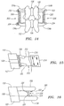
- FIGS. 6A-B prosthetic facets and facet joints are shown.
- some or all of the facet is removed to provide access to implant one or more prosthetic structures.
- many spinal procedures create loss of height of the disc or similar unintended results.
- each prosthetic facet 190 includes an attachment arm 192 that is generally elongated and curved to match the shape and structure of the native facet.
- the attachment arm 192 terminates in an endplate 194 that mimics the facing surface of the native facet.
- the attachment arm 192 is attached to its associated vertebral body by one or more screws 196 or other suitable attachment mechanism.
- a facet stabilizing member 170 identical to those described above in relation to FIG. 5 , is interposed between a pair of prosthetic facets 190, with the facet endplates 194 serving as the endplates for the facet stabilizing member 170. (See, in particular, FIG. 6B ).
- the prosthetic facet joint is oriented to be on plane with the native facet. Thus, the orientation of the facet joint will vary between vertebral segments.
- FIG. 7 illustrates a multi-level stabilization over several adjacent vertebral segments using the prosthetic facets 190.
- a first prosthetic facet 190 is attached to the sacrum 119, and additional prosthetic facets 190 are attached to the L5 and L4 vertebrae.
- the lateral stabilization device 200 includes an upper attachment arm 202a adapted to be attached to the superior vertebral body 100 by one or more screws 204 or other attachment mechanism, and a lower attachment arm 202b adapted to be attached to the inferior vertebral body 102 by one or more screws 204 or other attachment mechanism.
- the device also includes a stabilization member 206.
- the stabilization member 206 may include a spring, a combination of springs, a damping mechanism, or other mechanism that provides a desired stabilization function.
- the stabilization member includes a structure identical to the facet stabilization member 170 described above in relation to FIG. 5 .
- the lateral stabilization device 200 is attached to the lateral surfaces of the pair of adjacent vertebral bodies 100, 102. In a particularly preferred embodiment, a lateral stabilization device 200 is attached on both lateral sides of the pair of vertebral bodies.
- FIG. 9 shows a pair of adjacent vertebral bodies 100, 102 having both a posterior stabilization device 210 and an anterior stabilization device 220 attached to each of the pair of vertebral bodies.
- the posterior stabilization device 210 includes a pair of pedicle screws 212, one attached to each of the superior vertebral body 100 and the inferior vertebral body 102.
- a stabilization member 212 extends between and interconnects the pair of pedicle screws 212.
- the stabilization member 214 may comprise a load bearing dynamic structure that is spring loaded, that includes a damping member, or any combination of such structures.
- the anterior stabilization device 220 includes an anterior element 222, the details of which are best shown in FIG. 9B .
- the anterior element 222 is preferably formed of a material having superelastic properties, and includes a shape that allows the anterior element 222 to be constrained for a minimally invasive implantation procedure. As shown, the anterior element 222 includes an attachment hole 224 at each end, and a central portion 226 that includes a pair of side bands 228a-b that define a central aperture 230. The anterior element 222 may be rolled or compressed into a low profile contracted state for implantation. Once introduced, the anterior element is partially released from the contracted state and attached to the pair of vertebral bodies adjacent to the damaged disc 108. The anterior element 222 is preferably attached by screws or other suitable mechanisms. Once attached, the anterior element 222 is fully extended to its operative state and is capable of bearing loads to provide stabilization to the vertebral segments.
- the anterior stabilization device 220 may be used alone, in combination with the posterior stabilization device 210 illustrated in FIG. 9A , or in combination with any other suitable stabilization device or structure.
- a combination of stabilization devices it may be possible to provide additional amounts or types of stabilization and unloading of the vertebral segment than is possible by use of only a single stabilization structure.
- the dynamic stabilization devices include a posterior spacer and one or more restrictor bands.
- the spacer may be integrated with the restrictor band(s), or it may be provided independently of the restrictor band(s).
- the posterior spacer 240 is generally in the shape of a short cylinder, having a central through-hole 242 and an upper surface 244 and lower surface 246.
- the posterior spacer 240 may optionally be provided in any other form or shape, as described more fully below.
- the spacer 240 is preferably formed of a generally compliant biocompatible material, such as a polyurethane, silicone, or other suitable polymeric material.
- the spacer 240 is generally located between the spinous processes of a pair of adjacent vertebral bodies. The spacer maintains the spacing between the vertebral bodies while allowing a desired amount of relative motion between the two vertebral bodies.
- the restrictor band(s) 250 are each preferably formed in a continuous loop and are formed of a relatively elastic biocompatible material, such as any number of elastomeric and/or polymeric materials suitable for the purpose.
- the restrictor band(s) 250 are linked to the posterior spine to provide both stability and compliance.
- the band(s) 250 are attached either to the lamina by way of attachment screws 252 or other suitable attachment mechanisms (see FIG. 10C , or they are looped directly onto the spinous processes 106 of the pair of vertebral bodies (see FIGS. 10B, 10D ).
- the materials, sizes, structures, and routing of the restrictor band(s) 250 are able to be tailored to obtain a desired type and degree of constraint.
- a routing pattern that is oriented relatively more diagonally, as in FIG. 10C will provide more resistance to torsional movement than will a routing pattern that is oriented more vertically, as in FIG. 10D .
- Other routing variations are also possible, as will be recognized by those skilled in the art.
- the spinal stabilization device 260 includes a superior attachment member 262 and an inferior attachment member 264, for attachment to a superior vertebral body 100 and an inferior vertebral body 100, respectively.
- the superior attachment member 262 and inferior attachment member 264 may be attached to the spinous processes 106 of the respective vertebral bodies 100, 102, as shown, or they may be attached to the pedicles or other suitable portions of the vertebral bodies.
- the attachment members 262, 264 preferably comprise screws, although other attachment members may be used as desired or as suitable.
- the stabilization device 260 includes one or more spring elements 266 that each extend between and interconnect the superior attachment member 262 and inferior attachment member 264.
- Each spring element 266 is preferably formed of nickel titanium alloy (Nitinol) or other suitable biocompatible shape memory material.
- Nitinol nickel titanium alloy
- the shape and properties of each spring element 266 are able to be altered at any time, either prior to implantation or after implantation, by heating the spring element, for example, using an electric current.
- the shape memory material may be trained by a heating process to conform to a predetermined shape upon being heated to a predetermined temperature, in a manner known to those skilled in the art. Thus, the user is able to alter the shape, size, or performance characteristics of the spring elements 266 through application of heat to those members.
- leads may be placed in contact with the spring elements 266 under X-ray or other guidance after implantation in the spine of a patient. Electric current is then supplied to the spring elements 266 through the leads, allowing the user to alter the size, shape, or performance characteristics of the spring elements.
- spring elements 266 shown in the embodiment illustrated in FIG. 11 are generally straight struts, the spring elements 266 may alternatively be provided in any shape, size, or orientation suitable for a given application.
- FIG. 12 another spinal stabilization device is shown in a generally schematic representation.
- the spinal stabilization device illustrated in FIG. 12 is adapted to transfer loads from one motion segment to adjacent segments.
- Three adjacent vertebral bodies 270, 272, and 274 are shown schematically in the Figure.
- a pair of interconnected stabilization devices 276 are attached to each of the three vertebral bodies.
- Each stabilization device 276 includes a fixation element 278 attached to each vertebral body and a linkage 280 extending between and attached to each adjacent pair of fixation elements 278.
- Each of the fixation elements 278 comprises a bearing structure or similar mechanism that provides the capability of rotating the attached linkage 280.
- a first vertebral segment such as vertebral body 270
- a load placed upon the adjacent vertebral segments such as vertebral bodies 272 and 274.
- the transfer of this load through rotation of the fixation elements 278 imposing loading upon the attached linkages 280 influences the upper vertebral body 270 to move to the left, as shown by arrow "B". This movement is consistent with the natural movement of the spine when the body twists. Compression and flexion loads are transferred in a similar manner.
- each of the fixation elements 278 is preferably in the form of a bearing or similar rotatable structure that provides rotational movement as represented by the arrows "C".
- the linkages 280 may comprise a spring element or multiple spring elements having a size, shape, spring constant, and other characteristics that provide the desired amount of load transfer in response to rotation of the fixation elements 278.
- two stabilization devices 276 are shown in the Figure, more or fewer devices may be used depending upon the degree of stabilization needed or desired.
- the stabilization devices 276 may also extend between more (e.g., four or more) or fewer (e.g., two) adjacent vertebral segments.
- FIG. 13 a multi-component dynamic stabilization system is shown schematically.
- Current dynamic spinal stabilization systems are typically either interspinous devices (i.e., connected between the spinous processes of adjacent vertebral bodies) or pedicle screw based devices (i.e., connected between pedicle screws attached to the pedicles of adjacent vertebral bodies).
- interspinous devices i.e., connected between the spinous processes of adjacent vertebral bodies
- pedicle screw based devices i.e., connected between pedicle screws attached to the pedicles of adjacent vertebral bodies.
- each of the pedicle based systems 292a-b comprises a spring loaded or other suitable structure that provides a distracting force, represented by arrows "D", that tends to unload the disc 108.
- the interspinous system 290 includes a spring loaded or other suitable structure that biases the spinous processes 106 of the adjacent vertebral bodies 100, 102 toward one another, as represented by arrows E.
- the combined action of the interspinous system 290 and the pedicle based systems 292a-b creates a moment that relives pressure from the disc 108.
- interspinous system 290 and/or the pedicle based systems 292a-b of the foregoing embodiment may be constructed such that one or more of the systems is externally adjustable, as described, for example, in relation the devices illustrated in FIG. 11 .
- a dynamic stabilization device 300 is attached to each of the vertebral bodies at a position at or near the transverse processes 104a-b of each vertebral body 100, 102.
- Each dynamic stabilization device 300 includes an upper attachment screw 302 and a lower attachment screw 304.
- the screws 302, 304 may be placed through the transverse process to the vertebral body, or they may be attached direction to the vertebral body adjacent the transverse process 104a-b.
- a loading member 306 is attached to each of the upper attachment screw 302 and the lower attachment screw 304 and extends therebetween.
- the loading member 306 is adapted to stabilize the adjacent vertebral bodies by providing an appropriate level of distraction or attraction forces.
- the loading member 306 may comprises a spring, a set of springs, a damping member, or any other suitable structure such as those described elsewhere herein.
- FIG. 15 provides a schematic illustration of an externally adjustable dynamic stabilization system.
- the system includes an upper screw 310 and lower screw 312 extending posteriorly from a superior vertebral body 100 and an inferior vertebral body 102, respectively. Each screw extends outside of the patient's body.
- a stabilization member 314 is attached to each of the screws 310, 312 on the external surface of the patient's back, i.e., outside the surface of the skin 316.
- the stabilization member 316 may be a spring loaded, multiple spring loaded, damping mechanism, or any other suitable stabilization system such as those described elsewhere herein.
- the stabilization system 316 is readily adjustable postoperatively because it is located externally of the patient. Accordingly, any adjustments to the performance of the system may be made easily and without the need for additional surgical intervention.
- FIG. 16 is a schematic illustration of another adjustable stabilization system.
- the spinal stabilization system 320 includes an upper pot 322 attached to the spinous process 106 of a superior vertebral body 100, and a lower pot 324 attached to the spinous process 106 of an inferior vertebral body 102.
- Each of the upper pot 322 and lower pot 324 forms a portion of the attachment mechanism for the stabilization device.
- the upper pot 322 and lower pot 324 may be attached to the spinous processes 106 by any suitable mechanism, such as one or more screws.
- Each of the upper pot 322 and lower pot 324 includes a cylindrical portion that is adapted receive a connector 326 located at each of the upper end and lower end of a spring 328.
- Each of the connectors 326 engages one of the upper pot 322 and lower pot 324, thereby allowing the spring 328 to provide a distracting force to the vertebral bodies 100, 102.
- the upper pot 322 and lower pot 324 are generally hollow, it is possible to partially fill one or both of the pots 322, 324 to decrease the effective length of the spring 328 extending between the pots, i.e., partially filling the pots causes the connectors to engage the filler material at a level removed from the bottom of the pot 322, 324.
- Either or both of the pots 322, 324 may be partially filled with bone cement containing polymethylmethacrylate (PMMA) or another suitable material.
- PMMA polymethylmethacrylate
- the filling operation may be performed postoperatively by way of a percutaneous access, thereby eliminating the need for additional surgical intervention.
- FIG. 17 provides an illustration of another dynamic stabilization system.
- the stabilization system 340 includes a DIAMTM type intervertebral spacer 342 interposed between the spinous processes 106 of a pair of adjacent vertebral bodies 100, 102.
- DIAMTM type intervertebral spacers are commercially available and are produced by Medtronic Sofamor Danek.
- the spacer 342 is generally "H" shaped, including a relatively narrow center section located between relatively wider side sections. This shape allows the spacer to be effectively sandwiched between the spinous processes 106 of a pair of adjacent vertebral bodies 100, 102, as shown in FIG. 17 .
- the spacer 342 is a silicone device covered with polyethylene, and functions by reducing loading of the disc, restoring the posterior tension band, realigning the facets, and restoring the foramenal height.
- a stabilizing disc 344 is interposed between the spinous processes 106 in place of a portion of the spacer 340.
- the stabilizing disc 344 has a structure and is constructed in a manner identical to the facet stabilizing member 170 described above in relation to FIG. 5 , having a core member located between a pair of endplates.
- the stabilizing disc 344 allows for compression and rotation, if needed.
- the stabilizing disc 344 also facilitates lateral bending.
- the '033 application describes, inter alia, spinal treatment methods that combine a prosthetic intervertebral disc with a dynamic stabilization system.
- Each of the dynamic stabilization systems described in the present application are suitable for use in combination with prosthetic intervertebral discs such as those described in the '033 application, and others described in United States Patent Application 2005/0228500 .
- an exemplary prosthetic intervertebral disc 1100 is shown in FIG. 18 , which is reproduced from FIG. 3 of the '033 application and which was also described in the '276 application.
- This prosthetic disc is described for exemplary purposes, and is not intended to represent the only type of prosthetic disc that is suitable for use in combination with the devices and systems described elsewhere herein.
- the prosthetic disc 1100 has an integrated structure that includes an upper endplate 1110, a lower endplate 1120, and a core member 1130 retained between the upper endplate 1110 and the lower endplate 1120.
- One or more fibers 1140 are wound around the upper and lower endplates to attach the endplates to one another.
- the wind of the fibers 1140 allows a degree of axial rotation, bending, flexion, and extension by and between the endplates.
- An annular capsule 1150 is optionally provided in the space between the upper and lower endplates, surrounding the core member 1130 and the fibers 1140.
- the upper endplate 1110 and lower endplate 1120 are generally flat, planar members, and are fabricated from a biocompatible material that provides substantial rigidity.
- the upper surface of the upper endplate 1110 and the lower surface of the lower endplate 1120 are preferably each provided with a mechanism for securing the endplate to the respective opposed surfaces of the upper and lower vertebral bodies between which the prosthetic disc is to be installed.
- the upper endplate 1110 includes a plurality of anchoring fins 1111a-b.
- the anchoring fins 1111a-b are intended to engage mating grooves that are formed on the surfaces of the upper and lower vertebral bodies to thereby secure the endplate to its respective vertebral body.
- the anchoring fins 1111a-b extend generally perpendicularly from the generally planar external surface of the upper endplate 1110, i.e., upward from the upper side of the endplate as shown in Figure 18 .
- Each of the anchoring fins 1111a-b has a plurality of serrations 1112 located on the top edge of the anchoring fin.
- the serrations 1112 are intended to enhance the ability of the anchoring fin to engage the vertebral body and to thereby secure the upper endplate 1110 to the spine.
- the lower surface of the lower endplate 1120 includes a plurality of anchoring fins 1121a-b.
- the anchoring fins 1121a-b on the lower surface of the lower endplate 1120 are identical in structure and function to the anchoring fins l111a-b on the upper surface of the upper endplate 1110, with the exception of their location on the prosthetic disc.
- the anchoring fins 1111, 1121 may optionally be provided with one or more holes or slots 1115, 1125.
- the holes or slots help to promote bony ingrowth that assist in anchoring the prosthetic disc 1100 to the vertebral bodies.
- the upper endplate 1110 contains a plurality of slots 1114 through which the fibers 1140 may be passed through or wound, as shown.
- the actual number of slots 1114 contained on the endplate is variable.
- the purpose of the fibers 1140 is to hold the upper endplate 1110 and lower endplate 1120 together and to limit the range-of-motion to mimic the range-of-motion and torsional and flexural resistance of a natural disc.
- the core member 1130 is intended to provide support to and to maintain the relative spacing between the upper endplate 1110 and lower endplate 1120.
- the core member 1130 is made of a relatively compliant material, for example, polyurethane or silicone, and is typically fabricated by injection molding.
- a preferred construction for the core member includes a nucleus formed of a hydrogel and an elastomer reinforced fiber annulus.
- the shape of the core member 1130 is typically generally cylindrical or bean-shaped, although the shape (as well as the materials making up the core member and the core member size) may be varied to obtain desired physical or performance properties.
- the core member 1130 shape, size, and materials will directly affect the degree of flexion, extension, lateral bending, and axial rotation of the prosthetic disc.
- the annular capsule 1150 is preferably made of polyurethane or silicone and may be fabricated by injection molding, two-part component mixing, or dipping the endplate-core-fiber assembly into a polymer solution.
- a function of the annular capsule is to act as a barrier that keeps the disc materials (e.g., fiber strands) within the body of the disc, and that keeps natural in-growth outside the disc.
- prosthetic disc 1100 may be implanted by surgical techniques described in the '033 and '500 applications and elsewhere. As described above, it will often be advantageous to combine the prosthetic intervertebral disc with any of the other devices, systems, and methods described herein to obtain synergistic therapeutic results in treatment of spinal disease, trauma, or other disorder.
Description
- The spine is comprised of twenty-four vertebrae that are stacked one upon the other to form the spinal column. The spine provides strength and support to allow the body to stand and to provide flexibility and motion. A Section of each vertebrae includes a passageway that provides passage of the spinal cord through the spinal column. The spine thereby encases and protects the spinal cord. The spinal cord also includes thirty-one pairs of nerve roots that branch from either side of the spinal cord, extending through spaces between the vertebrae known as the neural foramen.
- An intervertebral disc is located between each pair of vertebrae. The disc is composed of three component structures: (1) the nucleus pulposus; (2) the annulus fibrosus; and (3) the vertebral endplates. The disc serves several purposes, including absorbing shock, relieving friction, and handling pressure exerted between the superior and inferior vertebral bodies associated with the disc. The disc also relieves stress between the vertebral bodies, which stress would otherwise lead to degeneration or fracture of the vertebral bodies.
- Disorders of the spine comprise some of the costliest and most debilitating health problems facing the populations of the United States and the rest of the world, costing billions of dollars each year. Moreover, as these populations continue to age, the incidence of spinal disorders will continue to grow. Typical disorders include those caused by disease, trauma, genetic disorders, or other causes.
- The state of the art includes a number of treatment options. Medicinal treatments, exercise, and physical therapy are typical conservative treatment options. Less conservative treatment options include surgical intervention, including microdiscectomy, kyphoplasty, laminectomy, dynamic stabilization, disc arthroplasty, and spinal fusion. Traditionally, these treatment options have been applied in isolation, rather than in combination, using the most conservative treatment option that will provide a desired result.
- United States Patent Application
2007/0050033 , entitled "Prosthetic Intervertebral Discs," ("the '033 application"), was filed September 1, 2005, and is assigned to Spinal Kinetics, Inc. The '033 application describes, inter alia, a treatment option that combines a prosthetic intervertebral disc with a dynamic stabilization system. - In 1992, Panjabi introduced a model of a dynamic spinal stabilization system that describes the interaction between components providing stability in the spine. This model defined spinal instability in terms of a region of laxity around the neutral resting position of a spinal segment, identified as the neutral zone." Panjabi, M M., "The stabilizing system of the spine. Part 11. Neutral zone and instability hypothesis." J Spinal Disord 5 (4): 390-397,1992b. There is some evidence that the neutral zone can be increased in cases of intervertebral disc degeneration, spinal injury and spinal fixation. Id. Panjabi has subsequently described dynamic stabilization systems that provide increased mechanical support while the spine is in the neutral zone and decreased support as the spine moves away from the neutral zone. See United States Published Patent Application No.
2004/0236329, published November 25, 2004 . -
WO 2006/055186 A2 , published after the priority date of the present invention and therefore at most admissible as prior art under Article 54(3) EPC, discloses a facet joint prosthesis comprising: an elongated upper arm curved forward and configured to attach to an upper vertebral body, an elongated lower attachment arm curved forward and configured to attach to a lower vertebral body, and a compressible stabilizing member comprising an upper endplate attached to the upper attachment arm, a lower endplate attached to the lower attachment arm, and a compressible core element separating the upper endplate from the lower endplate. -
EP 1 437 101 A2 discloses a facet joint prosthesis for replacing a natural facet joint comprising first and second facets. The prosthesis comprises an endplate having a superior outer surface adapted to attach to a superior facet, another endplate having an inferior outer surface adapted to attach to an inferior facet, and a compressible core element separating the upper endplate from the lower endplate to constrain relative movement between the facets. -
US 2005/209694 A1 discloses an artificial spinal joint. The joint, consisting of a flexible or rigid member or a pair of moveably-joined, flexible or rigid segments, is formed into a springlike shape, whose distal ends have feet with slots through which screws can be inserted to attach the artificial joint to vertebra whose facets (joints) are non-functional. - According to a first aspect of the present invention there is provided the prosthetic device of claim 1.
- According to a second aspect of the present invention there is provided the prosthetic device of claim 6. Embodiments of the invention are set out in the dependent claims.
- Devices, systems and methods for facet joint augmentation and
replacement are hereinafter described . The devices and systems are intended to stabilize the spine and to increase the foramenal space to thereby reduce the likelihood of nerve root impingement. In a first example, the stabilization and increase of foramenal space is accomplished by inserting a stabilizing member into the facet joint to restore the intra-foramenal distance. The stabilizing member comprises a structure that provides shock absorbance, cushioning, and support to the facet joint. In several examples, the stabilizing member comprises an encapsulated cushion. In embodiments, the stabilizing member comprises a structure having a pair of endplates separated by a resilient core member. - In a second example, some or all of the facets of each of the superior and inferior vertebral bodies are removed and replaced with a facet joint implant. In several embodiments, the facet joint implant includes an upper prosthetic facet for attachment to the superior vertebral body, and a lower prosthetic facet for attachment to the inferior vertebral body. Each prosthetic facet is attached to its respective vertebral body by screws or other similar mechanisms. Each prosthetic facet joint includes a pair of facing plates and a core member located between the pair of facing plates. The prosthetic facet is constructed and attached in a manner such that it closely mimics the functionality and performance of the natural facet joint.
- In a third example a lateral spinal stabilization device is provided. The lateral spinal stabilization device includes an upper attachment member and a lower attachment member for attaching to the lateral surfaces of each of the superior and inferior vertebral bodies, respectively, and a stabilizing member connected and extending between each of the upper and lower attachment members. The stabilizing member comprises a pair of endplates separated by a resilient core member.
- Each of the forgoing devices, structures, and methods is adapted to be used independently, or in combinations of two or more. Preferably, several devices, structures, or methods are used in combination to obtain desired results. In particular, each of the foregoing devices may be used in combination with a prosthetic intervertebral disc to obtain desired therapeutic results.
- Other and additional devices, apparatus, structures, and methods are described by reference to the drawings and detailed descriptions below. Of the devices hereinafter illustrated, only those shown in
Figures 6A, 6B ,7 are in accordance with the claimed invention, although the facet stabilising member ofFigure 5 is suitable for use in the prosthetic device of the present invention. The remaining drawings represent technical background that may be useful for understanding the prosthetic devices of the present invention. - The Figures contained herein are not necessarily drawn to scale, with some components and features being exaggerated for clarity.
-
Figure 1 is a lateral view of a pair of adjacent vertebral bodies, including representation of the foramen and nerve roots traversing the foramen. -
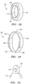
Figures 2A-G are illustrations of foramenal spacers. -
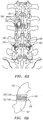
Figure 3 is a posterior view of a pair of adjacent vertebral bodies, including representation of the facets and facet joints. -
Figure 4 is a perspective view of an example of a facet joint stabilizing member. -
Figure 5 is a side view of another example of a facet joint stabilizing member shown implanted in a facet joint. -
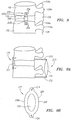
Figures 6A-B are illustrations of prosthetic facets. -
Figure 7 is an illustration of a portion of a spinal column having a plurality of prosthetic - facets in place of the native facets.
-
Figure 8 is a lateral view of a pair of vertebral bodies having a lateral stabilization device implanted therebetween. -
Figure 9A is a lateral view of a pair of vertebral bodies having an anterior stabilization device and a posterior stabilization device implanted therebetween. -
Figure 9B is an illustration of an anterior stabilization device. -
Figure 10A is an illustration of a spacer member. -
Figures 10B-D are illustrations of posterior dynamic stabilization devices including a spacer member and restrictor bands. -
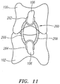
Figure 11 is a posterior view of another dynamic stabilization system. -
Figure 12 is a posterior view of another dynamic stabilization system -
Figure 13 is a lateral view of another dynamic stabilization system. -
Figure 14 is a posterior view of another dynamic stabilization system. -
Figure 15 is a lateral view of another dynamic stabilization system. -
Figure 16 is a lateral view of another dynamic stabilization system. -
Figure 17 is a lateral view of another dynamic stabilization system. -
Figure 18 is a three dimensional cross-sectional view of an exemplary prosthetic intervertebral disc. - Before the present invention is described, it is to be understood that this invention is not limited to particular embodiments described, as such may, of course, vary. It is also to be understood that the terminology used herein is for the purpose of describing particular embodiments only, and is not intended to be limiting, since the scope of the present invention will be limited only by the appended claims.
- Where a range of values is provided, it is understood that each intervening value, to at least the tenth of the unit of the lower limit unless the context clearly dictates otherwise, between the upper and lower limit of that range and any other stated or intervening value in that stated range is encompassed within the invention. The upper and lower limits of these smaller ranges may independently be included in the smaller ranges is also encompassed within the invention, subject to any specifically excluded limit in the stated range. Where the stated range includes one or both of the limits, ranges excluding either or both of those included limits are also included in the invention.
- Unless defined otherwise, all technical and scientific terms used herein have the same meaning as commonly understood by one of ordinary skill in the art to which this invention belongs.
- Turning now to the drawings,
FIG. 1 illustrates a pair of adjacent vertebral bodies, including a superiorvertebral body 100 and an inferiorvertebral body 102. Each vertebral body includes a pair oftransverse processes 104a-b and aspinous process 106 extending generally posteriorly from eachvertebral body disc 108 is located between the superiorvertebral body 100 and the inferiorvertebral body 102. Thespinal cord 110 extends through a central passage formed by the spinal column, andnerve roots 112 transverse theforamenal space 114 defined by the pair of vertebral bodies. - When the disc is damaged due to trauma, disease, or other disorder, the superior
vertebral body 100 and inferiorvertebral body 102 tend to collapse upon each other, thereby decreasing the amount of space formed by theforamen 114. This result also commonly occurs when the vertebral bodies are afflicted with disease or are fractured or otherwise damaged. When the foramenal space is decreased, thevertebral bodies nerve root 112, causing discomfort, pain, and possible damage to the nerve root. The foramenal spacers described herein are intended to alleviate this problem by maintaining the foramenal opening and otherwise protecting the nerve root from impingement by the vertebral bodies. - Turning to
FIGS. 2A through 2G , several foramenal spacer embodiments are shown. In a first embodiment, shown inFIGS. 2A-D , theforamenal spacer 120 includes a superior C-shapedmember 122 and an inferior C-shapedmember 124. The pair of C-shaped members preferably include an attachment mechanism or a pair of mating surfaces. For example, as shown inFIG. 2B , the superior C-shapedmember 122 is provided with agroove 126 on each of its inferior-facingsurfaces 128, whereas the inferior C-shapedmember 124 includes amating tab 130 on each of its superior-facingsurfaces 132. Alternatively, the tabs may be place on the superior C-shaped member and the grooves on the inferior C-shaped member, or still other attachment members may be used, such as a snap-fit mechanism or other similar structure. In still other embodiments, the mating surfaces 128, 132 may simply butt up against one another to form a butt-joint that prevents collapse of the foramenal space. When combined, the pair of C-shaped members define a generally disc-shapedmember 134 having a central through-hole 136. The central through-hole 136 has a size and shape adapted to allow thenerve root 112 to pass without impingement as shown, for example, inFIGS. 2C and 2D . - Turning to
FIG. 2E , theforamenal spacer 120 may be provided with anouter layer 140 that includes a coating of a soft, conformable material. Theouter layer 140 preferably covers all of the external-facing surfaces of theforamenal spacer 120, and particularly those that are positioned to engage the vertebral body surfaces. Theouter layer 140 is preferably formed of a soft, conformable biocompatible material such as silicone, polyurethane, or other similar polymeric materials, and may be applied to theforamenal spacer 120 by methods well-known in the art. Theouter layer 140 may provide structural protection to the vertebral bodies forming the foramenal space, and also allows theforamenal spacer 120 to adapt to the varying foramenal geometries formed by the vertebral bodies. - An optional inner layer or
liner 142 may be provided on the exposed surfaces defining the through-hole 136. The inner layer orliner 142 is preferably formed of a coating of soft and/or low-friction material to provide an atraumatic surface for passage of thenerve root 112. Preferably, the inner layer orliner 142 is formed of similar materials as those used for theouter layer 140, including silicone, polyurethane, or other polymeric materials. Alternatively, the inner layer orliner 142 may comprise a coating of polyethylene, PTFE, or other similar material. - In addition, an optional spring member, gasket, cushion, or other similar material or device (not shown in the drawings) may be interposed between the superior C-shaped
member 122 and the inferior C-shapedmember 124. Preferably, the spring member (or the like) may be located on the abutting surfaces of the two C-shaped members. This spring member (or the like) provides thespacer 120 with the capability of vertical expansion and contraction as the spring member extends and compresses, thereby providing a range of motion for supporting the foramenal space. - Turning now to
FIG. 2F , another foramenal spacer embodiment is shown. In this embodiment, theforamenal spacer 120 includes anupper segment 150 and alower segment 156. Theupper segment 150 includes anexternal surface 152 that has a shape adapted to engage the portion of the superior vertebral body defining theforamenal space 114. Similarly, thelower segment 156 includes anexternal surface 158 that has a shape adapted to engage the portion of the inferior vertebral body defining theforamenal space 114. Aninternal surface 154 of theupper segment 150 includes a curved portion that is adapted to rotatably engage a mating curved portion of theexternal surface 158 of thelower segment 156. In this way, theupper segment 150 andlower segment 156 are rotationally connected to one another, i.e., theupper segment 150 andlower segment 152 function similar to a bearing having a center of rotation. When theupper segment 150 is attached to the superiorvertebral body 100, and the lower segment is connected to the inferiorvertebral body 102, theforamenal spacer 120 allows the two vertebral bodies to pivot relative to one another, thereby providing an additional range of motion. Theforamenal spacer 120 shown inFIG. 2F also optionally includes theouter layer 140 and inner layer orliner 142 described above in relation toFIG. 2E . - The
foramenal spacer 120 may be implanted by any appropriate surgical technique, including accessing the foramenal space by either a posterior approach or a lateral approach. The lateral approach is believed to provide optimal access to find exposure of the foramen, but techniques for posterior lumbar interbody fusion (PLIF) and transforamenal lumbar interbody fusion (TLIF) also provide sufficient access. Once access is gained, theforamenal spacer 120 is preferably attached to the pedicle or other anatomic structure that allows extension of the spacer into theforamenal space 114. For example, theforamenal spacer 120 may be press fit into theforamen 116, as illustrated inFIG. 2G , or a tab (not shown) may be provided for attaching theforamenal spacer 120 to the pedicle or other anatomical structure. - Turning next to
FIG. 3 , a posterior view of a pair of adjacent vertebral bodies is shown. The Figures illustrates a superiorvertebral body 100 and an inferiorvertebral body 102. Each vertebral body includes a pair oftransverse processes 104a-b and aspinous process 106 extending generally posteriorly from eachvertebral body spinal cord 110 extends through a central passage formed by the spinal column, andnerve roots 112 transverse theforamenal space 114 defined by the pair of vertebral bodies. A facet joint 118 is formed by a pair of facing facets, one each from the superior and inferior vertebral bodies. - Several of the known devices and systems for posterior spinal stabilization are designed and provide the function of opening the foramen or maintaining the foramenal spacing in order to off-load the nerve that traverses the foramen. This is commonly done by attaching a device to the pedicles of each of the vertebral bodies and providing a distracting force between the attachment members. Several alternative and novel devices and methods are described herein.
- Turning to
FIG. 4 , afacet stabilizing member 170 is shown. Thefacet stabilizing member 170 preferably includes acore member 172 encased in ajacket 174. Thecore member 172 is preferably formed of a hydrogel, polyurethane, or other polymeric material suitable for providing the shock absorbing and spacing function necessary to stabilize the facet joint. Thejacket 174 may be a woven fabric of biocompatible material and is intended to maintain the integrity and shape of thecore member 172 and to otherwise provide structural strength to thefacet stabilizing member 170. Thefacet stabilizing member 170 has a size and shape adapted to be placed in the facet joint 118 thereby provide stabilization to the joint and to prevent collapse of the foramenal space. - Turning to
FIG. 5 , another embodiment of afacet stabilizing member 170 is shown. In this embodiment, the spinal stabilizingmember 170 includes anupper endplate 180, alower endplate 182, and acore member 184 extending between and interconnecting theupper endplate 180 andlower endplate 182. Preferably, the facet stabilizing member also includes a plurality offibers 186 wound between and interconnecting theupper endplate 180 andlower endplate 182. The construction and materials of thefacet stabilizing member 170 shown inFIG. 5 are similar to the construction and materials of the prosthetic intervertebral disc described below in relation toFIG. 18 , and to several of the prosthetic intervertebral discs described in United States Patent Application2005/0228500, filed July 30, 2004 , and United States Patent Application2007/0050033, filed September 1, 2005 . Other prosthetic discs described in the foregoing applications may also be adapted for use as afacet stabilizing member 170 as described herein. The size of thefacet stabilizing member 170 is typically smaller than the sizes of the prosthetic discs described in the foregoing applications, but the overall construction of the structure is preferably the same. - The
facet stabilizing member 170 is implanted between the pair of opposed facets associated with the pair of adjacent vertebral bodies. Additional features, such as fins, fixation members, or other structures (not shown), may also be incorporated on thefacet stabilizing member 170 to limit translation. The facet joint is synovial, therefore requiring implantation through the capsule. Access to the facet joint is obtained by any of the methods described above in relation to implantation of the foramenal spacer. - Turning to
FIGS. 6A-B , prosthetic facets and facet joints are shown. During many spinal surgical procedures, particularly those including approach by the posterior, some or all of the facet is removed to provide access to implant one or more prosthetic structures. Similarly, many spinal procedures create loss of height of the disc or similar unintended results. In these cases, or in cases in which the facets or facet joints become damaged through trauma, disease, or other disorder, it may be desirable to replace some or all of the facet with a prosthetic device to restore stabilization to the affected spinal segments. - In
FIG. 6A , a number ofprosthetic facets 190 are shown as implanted in several locations on a spinal column. Eachprosthetic facet 190 includes anattachment arm 192 that is generally elongated and curved to match the shape and structure of the native facet. Theattachment arm 192 terminates in anendplate 194 that mimics the facing surface of the native facet. Theattachment arm 192 is attached to its associated vertebral body by one ormore screws 196 or other suitable attachment mechanism. Afacet stabilizing member 170, identical to those described above in relation toFIG. 5 , is interposed between a pair ofprosthetic facets 190, with thefacet endplates 194 serving as the endplates for thefacet stabilizing member 170. (See, in particular,FIG. 6B ). As shown inFIG. 6A , the prosthetic facet joint is oriented to be on plane with the native facet. Thus, the orientation of the facet joint will vary between vertebral segments. -
FIG. 7 illustrates a multi-level stabilization over several adjacent vertebral segments using theprosthetic facets 190. A firstprosthetic facet 190 is attached to the sacrum 119, and additionalprosthetic facets 190 are attached to the L5 and L4 vertebrae. - Turning next to
FIG. 8 , a lateral stabilization device is shown. Thelateral stabilization device 200 includes an upper attachment arm 202a adapted to be attached to the superiorvertebral body 100 by one ormore screws 204 or other attachment mechanism, and alower attachment arm 202b adapted to be attached to the inferiorvertebral body 102 by one ormore screws 204 or other attachment mechanism. The device also includes astabilization member 206. Thestabilization member 206 may include a spring, a combination of springs, a damping mechanism, or other mechanism that provides a desired stabilization function. In a preferred embodiment, the stabilization member includes a structure identical to thefacet stabilization member 170 described above in relation toFIG. 5 . - Advantageously, the
lateral stabilization device 200 is attached to the lateral surfaces of the pair of adjacentvertebral bodies lateral stabilization device 200 is attached on both lateral sides of the pair of vertebral bodies. -
FIG. 9 shows a pair of adjacentvertebral bodies posterior stabilization device 210 and ananterior stabilization device 220 attached to each of the pair of vertebral bodies. Theposterior stabilization device 210 includes a pair of pedicle screws 212, one attached to each of the superiorvertebral body 100 and the inferiorvertebral body 102. Astabilization member 212 extends between and interconnects the pair of pedicle screws 212. Thestabilization member 214 may comprise a load bearing dynamic structure that is spring loaded, that includes a damping member, or any combination of such structures. Theanterior stabilization device 220 includes ananterior element 222, the details of which are best shown inFIG. 9B . Theanterior element 222 is preferably formed of a material having superelastic properties, and includes a shape that allows theanterior element 222 to be constrained for a minimally invasive implantation procedure. As shown, theanterior element 222 includes anattachment hole 224 at each end, and acentral portion 226 that includes a pair ofside bands 228a-b that define acentral aperture 230. Theanterior element 222 may be rolled or compressed into a low profile contracted state for implantation. Once introduced, the anterior element is partially released from the contracted state and attached to the pair of vertebral bodies adjacent to the damageddisc 108. Theanterior element 222 is preferably attached by screws or other suitable mechanisms. Once attached, theanterior element 222 is fully extended to its operative state and is capable of bearing loads to provide stabilization to the vertebral segments. - The
anterior stabilization device 220 may be used alone, in combination with theposterior stabilization device 210 illustrated inFIG. 9A , or in combination with any other suitable stabilization device or structure. By using a combination of stabilization devices, it may be possible to provide additional amounts or types of stabilization and unloading of the vertebral segment than is possible by use of only a single stabilization structure. - Turning now to
FIGS. 10A-D , several embodiments of a posterior dynamic stabilization device are shown. The dynamic stabilization devices include a posterior spacer and one or more restrictor bands. As explained below, the spacer may be integrated with the restrictor band(s), or it may be provided independently of the restrictor band(s). - Turning first to
FIG. 10A , aposterior spacer 240 is shown. Theposterior spacer 240 is generally in the shape of a short cylinder, having a central through-hole 242 and anupper surface 244 andlower surface 246. Theposterior spacer 240 may optionally be provided in any other form or shape, as described more fully below. Thespacer 240 is preferably formed of a generally compliant biocompatible material, such as a polyurethane, silicone, or other suitable polymeric material. As shown inFIGS. 10B-D , thespacer 240 is generally located between the spinous processes of a pair of adjacent vertebral bodies. The spacer maintains the spacing between the vertebral bodies while allowing a desired amount of relative motion between the two vertebral bodies. - The restrictor band(s) 250 are each preferably formed in a continuous loop and are formed of a relatively elastic biocompatible material, such as any number of elastomeric and/or polymeric materials suitable for the purpose. The restrictor band(s) 250 are linked to the posterior spine to provide both stability and compliance. The band(s) 250 are attached either to the lamina by way of attachment screws 252 or other suitable attachment mechanisms (see
FIG. 10C , or they are looped directly onto thespinous processes 106 of the pair of vertebral bodies (seeFIGS. 10B, 10D ). The materials, sizes, structures, and routing of the restrictor band(s) 250 are able to be tailored to obtain a desired type and degree of constraint. For example, a routing pattern that is oriented relatively more diagonally, as inFIG. 10C , will provide more resistance to torsional movement than will a routing pattern that is oriented more vertically, as inFIG. 10D . Other routing variations are also possible, as will be recognized by those skilled in the art. - Turning now to
FIG. 11 , another embodiment of a dynamic spinal stabilization device is shown. The device includes a construction and that provides the capability of adjusting the performance characteristics of the stabilization device after it has been implanted. In the illustrated embodiment, thespinal stabilization device 260 includes asuperior attachment member 262 and aninferior attachment member 264, for attachment to a superiorvertebral body 100 and an inferiorvertebral body 100, respectively. Thesuperior attachment member 262 andinferior attachment member 264 may be attached to thespinous processes 106 of the respectivevertebral bodies attachment members stabilization device 260 includes one ormore spring elements 266 that each extend between and interconnect thesuperior attachment member 262 andinferior attachment member 264. Eachspring element 266 is preferably formed of nickel titanium alloy (Nitinol) or other suitable biocompatible shape memory material. The shape and properties of eachspring element 266 are able to be altered at any time, either prior to implantation or after implantation, by heating the spring element, for example, using an electric current. The shape memory material may be trained by a heating process to conform to a predetermined shape upon being heated to a predetermined temperature, in a manner known to those skilled in the art. Thus, the user is able to alter the shape, size, or performance characteristics of thespring elements 266 through application of heat to those members. For example, leads may be placed in contact with thespring elements 266 under X-ray or other guidance after implantation in the spine of a patient. Electric current is then supplied to thespring elements 266 through the leads, allowing the user to alter the size, shape, or performance characteristics of the spring elements. - Although the
spring elements 266 shown in the embodiment illustrated inFIG. 11 are generally straight struts, thespring elements 266 may alternatively be provided in any shape, size, or orientation suitable for a given application. - Turning next to
FIG. 12 , another spinal stabilization device is shown in a generally schematic representation. The spinal stabilization device illustrated inFIG. 12 is adapted to transfer loads from one motion segment to adjacent segments. Three adjacentvertebral bodies interconnected stabilization devices 276 are attached to each of the three vertebral bodies. Eachstabilization device 276 includes afixation element 278 attached to each vertebral body and alinkage 280 extending between and attached to each adjacent pair offixation elements 278. - Each of the
fixation elements 278 comprises a bearing structure or similar mechanism that provides the capability of rotating the attachedlinkage 280. This allows a first vertebral segment, such asvertebral body 270, to be loaded in reaction to a load placed upon the adjacent vertebral segments, such asvertebral bodies vertebral body 274 moves to the right, as shown by arrow "A", the transfer of this load through rotation of thefixation elements 278 imposing loading upon the attachedlinkages 280 influences the uppervertebral body 270 to move to the left, as shown by arrow "B". This movement is consistent with the natural movement of the spine when the body twists. Compression and flexion loads are transferred in a similar manner. - As noted above, each of the
fixation elements 278 is preferably in the form of a bearing or similar rotatable structure that provides rotational movement as represented by the arrows "C". Thelinkages 280 may comprise a spring element or multiple spring elements having a size, shape, spring constant, and other characteristics that provide the desired amount of load transfer in response to rotation of thefixation elements 278. In addition, although twostabilization devices 276 are shown in the Figure, more or fewer devices may be used depending upon the degree of stabilization needed or desired. Thestabilization devices 276 may also extend between more (e.g., four or more) or fewer (e.g., two) adjacent vertebral segments. - Turning next to
FIG. 13 , a multi-component dynamic stabilization system is shown schematically. Current dynamic spinal stabilization systems are typically either interspinous devices (i.e., connected between the spinous processes of adjacent vertebral bodies) or pedicle screw based devices (i.e., connected between pedicle screws attached to the pedicles of adjacent vertebral bodies). Each of these types of dynamic stabilization devices functions by providing a distracting force that unloads thedisc 108. The system shown inFIG. 13 includes aninterspinous stabilization system 290 connected to thespinous processes 106 of a pair of adjacentvertebral bodies stabilization systems 292a-b (only one of the pedicle based systems is shown in the Figure) attached by pedicle screws to the pair of adjacentvertebral bodies systems 292a-b comprises a spring loaded or other suitable structure that provides a distracting force, represented by arrows "D", that tends to unload thedisc 108. Theinterspinous system 290, on the other hand, includes a spring loaded or other suitable structure that biases thespinous processes 106 of the adjacentvertebral bodies interspinous system 290 and the pedicle basedsystems 292a-b creates a moment that relives pressure from thedisc 108. - Advantageously, the
interspinous system 290 and/or the pedicle basedsystems 292a-b of the foregoing embodiment may be constructed such that one or more of the systems is externally adjustable, as described, for example, in relation the devices illustrated inFIG. 11 . - Turning next to
FIG. 14 , a pair of adjacentvertebral bodies dynamic stabilization device 300 is attached to each of the vertebral bodies at a position at or near thetransverse processes 104a-b of eachvertebral body dynamic stabilization device 300 includes anupper attachment screw 302 and alower attachment screw 304. Thescrews transverse process 104a-b. Aloading member 306 is attached to each of theupper attachment screw 302 and thelower attachment screw 304 and extends therebetween. Theloading member 306 is adapted to stabilize the adjacent vertebral bodies by providing an appropriate level of distraction or attraction forces. Theloading member 306 may comprises a spring, a set of springs, a damping member, or any other suitable structure such as those described elsewhere herein. -
FIG. 15 provides a schematic illustration of an externally adjustable dynamic stabilization system. The system includes anupper screw 310 andlower screw 312 extending posteriorly from a superiorvertebral body 100 and an inferiorvertebral body 102, respectively. Each screw extends outside of the patient's body. Astabilization member 314 is attached to each of thescrews skin 316. Thestabilization member 316 may be a spring loaded, multiple spring loaded, damping mechanism, or any other suitable stabilization system such as those described elsewhere herein. Advantageously, thestabilization system 316 is readily adjustable postoperatively because it is located externally of the patient. Accordingly, any adjustments to the performance of the system may be made easily and without the need for additional surgical intervention. -
FIG. 16 is a schematic illustration of another adjustable stabilization system. Thespinal stabilization system 320 includes anupper pot 322 attached to thespinous process 106 of a superiorvertebral body 100, and alower pot 324 attached to thespinous process 106 of an inferiorvertebral body 102. Each of theupper pot 322 andlower pot 324 forms a portion of the attachment mechanism for the stabilization device. Theupper pot 322 andlower pot 324 may be attached to thespinous processes 106 by any suitable mechanism, such as one or more screws. Each of theupper pot 322 andlower pot 324 includes a cylindrical portion that is adapted receive aconnector 326 located at each of the upper end and lower end of aspring 328. Each of theconnectors 326 engages one of theupper pot 322 andlower pot 324, thereby allowing thespring 328 to provide a distracting force to thevertebral bodies - Because the
upper pot 322 andlower pot 324 are generally hollow, it is possible to partially fill one or both of thepots spring 328 extending between the pots, i.e., partially filling the pots causes the connectors to engage the filler material at a level removed from the bottom of thepot pots -
FIG. 17 provides an illustration of another dynamic stabilization system. Thestabilization system 340 includes a DIAM™ typeintervertebral spacer 342 interposed between thespinous processes 106 of a pair of adjacentvertebral bodies spacer 342 is generally "H" shaped, including a relatively narrow center section located between relatively wider side sections. This shape allows the spacer to be effectively sandwiched between thespinous processes 106 of a pair of adjacentvertebral bodies FIG. 17 . Thespacer 342 is a silicone device covered with polyethylene, and functions by reducing loading of the disc, restoring the posterior tension band, realigning the facets, and restoring the foramenal height. - In addition, a stabilizing disc 344 is interposed between the
spinous processes 106 in place of a portion of thespacer 340. The stabilizing disc 344 has a structure and is constructed in a manner identical to thefacet stabilizing member 170 described above in relation toFIG. 5 , having a core member located between a pair of endplates. The stabilizing disc 344 allows for compression and rotation, if needed. The stabilizing disc 344 also facilitates lateral bending. The '033 application describes, inter alia, spinal treatment methods that combine a prosthetic intervertebral disc with a dynamic stabilization system. Each of the dynamic stabilization systems described in the present application are suitable for use in combination with prosthetic intervertebral discs such as those described in the '033 application, and others described in United States Patent Application2005/0228500 . - For example, an exemplary prosthetic
intervertebral disc 1100 is shown inFIG. 18 , which is reproduced fromFIG. 3 of the '033 application and which was also described in the '276 application. This prosthetic disc is described for exemplary purposes, and is not intended to represent the only type of prosthetic disc that is suitable for use in combination with the devices and systems described elsewhere herein. Turning to the Figure, theprosthetic disc 1100 has an integrated structure that includes anupper endplate 1110, alower endplate 1120, and acore member 1130 retained between theupper endplate 1110 and thelower endplate 1120. One ormore fibers 1140 are wound around the upper and lower endplates to attach the endplates to one another. The wind of thefibers 1140 allows a degree of axial rotation, bending, flexion, and extension by and between the endplates. Anannular capsule 1150 is optionally provided in the space between the upper and lower endplates, surrounding thecore member 1130 and thefibers 1140. Theupper endplate 1110 andlower endplate 1120 are generally flat, planar members, and are fabricated from a biocompatible material that provides substantial rigidity. - The upper surface of the
upper endplate 1110 and the lower surface of thelower endplate 1120 are preferably each provided with a mechanism for securing the endplate to the respective opposed surfaces of the upper and lower vertebral bodies between which the prosthetic disc is to be installed. For example, inFigure 18 , theupper endplate 1110 includes a plurality of anchoringfins 1111a-b. The anchoringfins 1111a-b are intended to engage mating grooves that are formed on the surfaces of the upper and lower vertebral bodies to thereby secure the endplate to its respective vertebral body. The anchoringfins 1111a-b extend generally perpendicularly from the generally planar external surface of theupper endplate 1110, i.e., upward from the upper side of the endplate as shown inFigure 18 . Each of the anchoringfins 1111a-b has a plurality ofserrations 1112 located on the top edge of the anchoring fin. Theserrations 1112 are intended to enhance the ability of the anchoring fin to engage the vertebral body and to thereby secure theupper endplate 1110 to the spine. - Similarly, the lower surface of the
lower endplate 1120 includes a plurality of anchoringfins 1121a-b. The anchoringfins 1121a-b on the lower surface of thelower endplate 1120 are identical in structure and function to the anchoring fins l111a-b on the upper surface of theupper endplate 1110, with the exception of their location on the prosthetic disc. - The anchoring fins 1111, 1121 may optionally be provided with one or more holes or
slots prosthetic disc 1100 to the vertebral bodies. - The
upper endplate 1110 contains a plurality ofslots 1114 through which thefibers 1140 may be passed through or wound, as shown. The actual number ofslots 1114 contained on the endplate is variable. The purpose of thefibers 1140 is to hold theupper endplate 1110 andlower endplate 1120 together and to limit the range-of-motion to mimic the range-of-motion and torsional and flexural resistance of a natural disc. - The
core member 1130 is intended to provide support to and to maintain the relative spacing between theupper endplate 1110 andlower endplate 1120. Thecore member 1130 is made of a relatively compliant material, for example, polyurethane or silicone, and is typically fabricated by injection molding. A preferred construction for the core member includes a nucleus formed of a hydrogel and an elastomer reinforced fiber annulus. The shape of thecore member 1130 is typically generally cylindrical or bean-shaped, although the shape (as well as the materials making up the core member and the core member size) may be varied to obtain desired physical or performance properties. For example, thecore member 1130 shape, size, and materials will directly affect the degree of flexion, extension, lateral bending, and axial rotation of the prosthetic disc. - The
annular capsule 1150 is preferably made of polyurethane or silicone and may be fabricated by injection molding, two-part component mixing, or dipping the endplate-core-fiber assembly into a polymer solution. A function of the annular capsule is to act as a barrier that keeps the disc materials (e.g., fiber strands) within the body of the disc, and that keeps natural in-growth outside the disc. - The foregoing
prosthetic disc 1100, or other suitable prosthetic discs, may be implanted by surgical techniques described in the '033 and '500 applications and elsewhere. As described above, it will often be advantageous to combine the prosthetic intervertebral disc with any of the other devices, systems, and methods described herein to obtain synergistic therapeutic results in treatment of spinal disease, trauma, or other disorder. - Accordingly, it is to be understood that the inventions that are the subject of this patent application are not limited to the particular embodiments described, as such may, of course, vary. The scope of the present invention is defined by the appended claims.
Claims (10)
- A prosthetic device having a frontal plane and lateral directions and configured to replace a pair of facets on adjacent upper and lower vertebral bodies and the facet joint between those facets in that spine from which spine the facets and facet joints to be replaced have been removed, comprising:a.) an elongated upper attachment arm (192) curved forward and medio-laterally in the frontal plane and configured to conform to and to attach at an upper end to a prepared facet site on the lateral posterior of the upper vertebral body, the facet site being prepared by the removal of the facet and the facet joint, and the elongated upper attachment arm being attached at an opposite end to a compressible stabilizing member,b.) an elongated lower attachment arm (192) curved rearward and medio-laterally in the frontal plane and configured to conform to and to attach at a lower end to a prepared facet site on the lateral posterior of the lower vertebral body, the facet site being prepared by the removal of the facet and the facet joint, and the elongated lower attachment arm being attached at an opposite end to the compressible stabilizing member, and,c.) the compressible stabilizing member (170) being oriented with respect to the upper and lower attachment arms to substantially match the orientation of the removed facet joint with respect to the upper and lower vertebrae after implantation of the device and fixedly attached to, interposed between, and separating the upper and lower attachment arms, the compressible stabilizing member further comprising an upper endplate (180, 194) fixedly attached to the elongated upper attachment arm, a lower endplate fixedly (182, 194) attached to the elongated lower attachment arm, a compressible core element (184) separating the upper endplate from the lower endplate, and a plurality of fibers (186) wound between and interconnecting the upper endplate and lower endplate.
- The prosthetic device of claim 1 further including fasteners (196) configured to attach the upper and lower attachment arms (192) to the upper and lower vertebral bodies.
- The prosthetic device of claim 2 where the fasteners comprise screws (196).
- The prosthetic device of any one of claims 1 to 3 where the compressible stabilizing member comprises a polymeric element.
- The prosthetic device of any one of claims 1 to 3 where the compressible stabilizing member (170) comprises a hydrogel element.
- A prosthetic device having a frontal plane and lateral directions and operative to replace in a spine, a facet on an upper vertebral body, two facets on a middle vertebral body, a facet on a lower vertebral body, and the facet joints respectively associated with those facets, from which spine the facets and facet joints to be replaced have been removed, comprisingi.) an elongated upper attachment arm attachable to the upper vertebral body,ii.) an elongated middle attachment arm attachable to the middle vertebral body, andiii.) an elongated lower attachment arm attachable to the lower vertebral body,the elongated upper attachment arm and the elongated middle attachment arm each fixedly attached to an upper compressible stabilizing member and the elongated middle attachment arm and the elongated lower attachment arm each fixedly attached to a lower compressible stabilizing member, wherein:a.) the elongated upper attachment arm comprises an upper end and a lower end opposite the upper end, the elongated upper attachment arm being curved forward and medio-laterally in the frontal plane and configured on the upper end to conform to and to attach to a prepared facet site on the lateral posterior of the upper vertebral body, the facet site being prepared by the removal of the facet and the facet joint, and
the elongated upper attachment arm being fixedly attached at the lower end to an upper endplate (194) of the upper compressible stabilizing memberb.) the upper compressible stabilizing member comprisesi.) the upper endplate fixedly attached to the elongated upper attachment arm,ii.) a lower endplate fixedly attached to the elongated middle attachment arm,iii.) a compressible core element interposed between and separating the upper endplate from the lower endplate, andiv.) further comprising a plurality of fibers wound between and interconnecting the upper endplate and the lower endplate,the upper compressible stabilizing member being oriented with respect to the elongated upper and middle attachment arms to substantially match the orientation of the removed facet joint with respect to the upper and middle vertebrae after implantation of the device andc. the elongated middle attachment arm comprisesi.) an upper portion curved forward and medio-laterally in the frontal plane and fixedly attached to the lower endplate of the upper compressible stabilizing member,ii.) a central portion curved medio-laterally in the frontal plane and configured to conform to and to attach at a prepared facet site on the lateral posterior of the middle vertebral body, the facet site being prepared by the removal of the two facets and the associated facet joints from the middle vertebral body, andiii.) a lower portion fixedly attached to an upper endplate of the lower compressible stabilizing memberd.) the lower compressible stabilizing member comprisesi.) the upper endplate fixedly attached to the elongated middle attachment armii.) a lower endplate fixedly attached to the elongated lower attachment arm,iii.) a compressible core element interposed between and separating the upper endplate from the lower endplate, andiv.) further comprising a plurality of fibers wound between and interconnecting the upper endplate and the lower endplate,the lower compressible stabilizing member being oriented with respect to the elongated middle and lower attachment arms to substantially match the orientation of the removed facet joint with respect to the middle and lower vertebrae after implantation of the device,
ande.) the elongated lower attachment arm comprises a first upper end and a second lower end opposite the first upper end, the elongated lower attachment arm being curved rearward and
medio-laterally in the frontal plane and configured on the second lower end to conform to and to attach to a prepared facet site on the lateral posterior of the lower vertebral body, the facet site being prepared by the removal of the facet and the facet joint, and
the elongated lower attachment arm being fixedly attached at the first upper end to the lower endplate of the second compressible stabilizing member. - The prosthetic device of claim 6 further including fasteners (196) configured to attach the upper, middle , and lower attachment arms to the upper, middle , and lower vertebral bodies.
- The prosthetic device of claim 7 where the fasteners comprise screws (196).
- The prosthetic device of any one of claims 6 to 8 where the first and second compressible stabilizing members each comprise a polymeric element.
- The prosthetic device of any one of claims 6 to 8 where the first and second compressible stabilizing members each comprise a hydrogel element.
Priority Applications (1)
| Application Number | Priority Date | Filing Date | Title |
|---|---|---|---|
| EP19174751.8A EP3545885A1 (en) | 2005-09-23 | 2006-08-31 | Facet prosthetic devices |
Applications Claiming Priority (3)
| Application Number | Priority Date | Filing Date | Title |
|---|---|---|---|
| US11/234,481 US20070083200A1 (en) | 2005-09-23 | 2005-09-23 | Spinal stabilization systems and methods |
| EP06802876A EP1937166A4 (en) | 2005-09-23 | 2006-08-31 | Spinal stabilization systems and methods |
| PCT/US2006/034360 WO2007037920A2 (en) | 2005-09-23 | 2006-08-31 | Spinal stabilization systems and methods |
Related Parent Applications (1)
| Application Number | Title | Priority Date | Filing Date |
|---|---|---|---|
| EP06802876A Division EP1937166A4 (en) | 2005-09-23 | 2006-08-31 | Spinal stabilization systems and methods |
Related Child Applications (1)
| Application Number | Title | Priority Date | Filing Date |
|---|---|---|---|
| EP19174751.8A Division EP3545885A1 (en) | 2005-09-23 | 2006-08-31 | Facet prosthetic devices |
Publications (2)
| Publication Number | Publication Date |
|---|---|
| EP3167849A1 EP3167849A1 (en) | 2017-05-17 |
| EP3167849B1 true EP3167849B1 (en) | 2019-06-05 |
Family
ID=37900215
Family Applications (3)
| Application Number | Title | Priority Date | Filing Date |
|---|---|---|---|
| EP06802876A Withdrawn EP1937166A4 (en) | 2005-09-23 | 2006-08-31 | Spinal stabilization systems and methods |
| EP16186386.5A Not-in-force EP3167849B1 (en) | 2005-09-23 | 2006-08-31 | Facet prosthetic devices |
| EP19174751.8A Withdrawn EP3545885A1 (en) | 2005-09-23 | 2006-08-31 | Facet prosthetic devices |
Family Applications Before (1)
| Application Number | Title | Priority Date | Filing Date |
|---|---|---|---|
| EP06802876A Withdrawn EP1937166A4 (en) | 2005-09-23 | 2006-08-31 | Spinal stabilization systems and methods |
Family Applications After (1)
| Application Number | Title | Priority Date | Filing Date |
|---|---|---|---|
| EP19174751.8A Withdrawn EP3545885A1 (en) | 2005-09-23 | 2006-08-31 | Facet prosthetic devices |
Country Status (8)
| Country | Link |
|---|---|
| US (6) | US20070083200A1 (en) |
| EP (3) | EP1937166A4 (en) |
| JP (1) | JP2009508633A (en) |
| CN (1) | CN101351160A (en) |
| AU (1) | AU2006295188A1 (en) |
| BR (1) | BRPI0616403A2 (en) |
| CA (1) | CA2623524A1 (en) |
| WO (1) | WO2007037920A2 (en) |
Families Citing this family (88)
| Publication number | Priority date | Publication date | Assignee | Title |
|---|---|---|---|---|
| US7282064B2 (en) * | 2003-02-11 | 2007-10-16 | Spinefrontier Lls | Apparatus and method for connecting spinal vertebrae |
| US7588590B2 (en) | 2003-12-10 | 2009-09-15 | Facet Solutions, Inc | Spinal facet implant with spherical implant apposition surface and bone bed and methods of use |
| US8333789B2 (en) | 2007-01-10 | 2012-12-18 | Gmedelaware 2 Llc | Facet joint replacement |
| US8998952B2 (en) * | 2004-02-17 | 2015-04-07 | Globus Medical, Inc. | Facet joint replacement instruments and methods |
| US8562649B2 (en) | 2004-02-17 | 2013-10-22 | Gmedelaware 2 Llc | System and method for multiple level facet joint arthroplasty and fusion |
| US8523904B2 (en) | 2004-03-09 | 2013-09-03 | The Board Of Trustees Of The Leland Stanford Junior University | Methods and systems for constraint of spinous processes with attachment |
| US7588578B2 (en) | 2004-06-02 | 2009-09-15 | Facet Solutions, Inc | Surgical measurement systems and methods |
| US8114158B2 (en) | 2004-08-03 | 2012-02-14 | Kspine, Inc. | Facet device and method |
| US20070083200A1 (en) * | 2005-09-23 | 2007-04-12 | Gittings Darin C | Spinal stabilization systems and methods |
| WO2007134113A2 (en) * | 2006-05-09 | 2007-11-22 | Raymedica, Llc | Systems and methods for stabilizing a functional spinal unit |
| US20080071379A1 (en) * | 2006-05-10 | 2008-03-20 | Mark Rydell | Intervertebral disc replacement |
| US8337528B2 (en) * | 2006-11-28 | 2012-12-25 | Anova Corporation | Methods and apparatus for stabilizing a spinal segment |
| US8172882B2 (en) | 2006-06-14 | 2012-05-08 | Spartek Medical, Inc. | Implant system and method to treat degenerative disorders of the spine |
| US20080033433A1 (en) * | 2006-08-01 | 2008-02-07 | Dante Implicito | Dynamic spinal stabilization device |
| US8162982B2 (en) | 2006-10-19 | 2012-04-24 | Simpirica Spine, Inc. | Methods and systems for constraint of multiple spine segments |
| US8187307B2 (en) * | 2006-10-19 | 2012-05-29 | Simpirica Spine, Inc. | Structures and methods for constraining spinal processes with single connector |
| JP2010506693A (en) * | 2006-10-19 | 2010-03-04 | シンピライカ スパイン, インコーポレイテッド | Structure and method for constraining spinous processes using a single connector |
| US8029541B2 (en) * | 2006-10-19 | 2011-10-04 | Simpirica Spine, Inc. | Methods and systems for laterally stabilized constraint of spinous processes |
| US20080262549A1 (en) * | 2006-10-19 | 2008-10-23 | Simpirica Spine, Inc. | Methods and systems for deploying spinous process constraints |
| US8109978B2 (en) * | 2006-11-28 | 2012-02-07 | Anova Corporation | Methods of posterior fixation and stabilization of a spinal segment |
| US8162993B2 (en) * | 2006-11-28 | 2012-04-24 | Anova Corporation | Methods of anterior fixation and stabilization of a spinal segment |
| US8075596B2 (en) | 2007-01-12 | 2011-12-13 | Warsaw Orthopedic, Inc. | Spinal prosthesis systems |
| US8337529B2 (en) * | 2007-02-13 | 2012-12-25 | Anova Corp. | Methods of bone, joint, and ligament reconstruction |
| EP1994901A1 (en) * | 2007-05-24 | 2008-11-26 | Bio Medical S.r.L. | Intervertebral support device |
| US8070779B2 (en) * | 2007-06-04 | 2011-12-06 | K2M, Inc. | Percutaneous interspinous process device and method |
| WO2008151096A1 (en) | 2007-06-05 | 2008-12-11 | Spartek Medical, Inc. | A deflection rod system for a dynamic stabilization and motion preservation spinal implantation system and method |
| US8048115B2 (en) | 2007-06-05 | 2011-11-01 | Spartek Medical, Inc. | Surgical tool and method for implantation of a dynamic bone anchor |
| US8083772B2 (en) | 2007-06-05 | 2011-12-27 | Spartek Medical, Inc. | Dynamic spinal rod assembly and method for dynamic stabilization of the spine |
| US7963978B2 (en) | 2007-06-05 | 2011-06-21 | Spartek Medical, Inc. | Method for implanting a deflection rod system and customizing the deflection rod system for a particular patient need for dynamic stabilization and motion preservation spinal implantation system |
| US8048122B2 (en) | 2007-06-05 | 2011-11-01 | Spartek Medical, Inc. | Spine implant with a dual deflection rod system including a deflection limiting sheild associated with a bone screw and method |
| US8002800B2 (en) | 2007-06-05 | 2011-08-23 | Spartek Medical, Inc. | Horizontal rod with a mounting platform for a dynamic stabilization and motion preservation spinal implantation system and method |
| US8021396B2 (en) | 2007-06-05 | 2011-09-20 | Spartek Medical, Inc. | Configurable dynamic spinal rod and method for dynamic stabilization of the spine |
| US8092501B2 (en) | 2007-06-05 | 2012-01-10 | Spartek Medical, Inc. | Dynamic spinal rod and method for dynamic stabilization of the spine |
| US8114134B2 (en) | 2007-06-05 | 2012-02-14 | Spartek Medical, Inc. | Spinal prosthesis having a three bar linkage for motion preservation and dynamic stabilization of the spine |
| US8162979B2 (en) | 2007-06-06 | 2012-04-24 | K Spine, Inc. | Medical device and method to correct deformity |
| US8403961B2 (en) * | 2007-06-22 | 2013-03-26 | Simpirica Spine, Inc. | Methods and devices for controlled flexion restriction of spinal segments |
| US20100036424A1 (en) | 2007-06-22 | 2010-02-11 | Simpirica Spine, Inc. | Methods and systems for increasing the bending stiffness and constraining the spreading of a spinal segment |
| US20110172708A1 (en) * | 2007-06-22 | 2011-07-14 | Simpirica Spine, Inc. | Methods and systems for increasing the bending stiffness of a spinal segment with elongation limit |
| US8460341B2 (en) * | 2007-06-27 | 2013-06-11 | Spinefrontier Inc | Dynamic facet replacement system |
| US20090005873A1 (en) * | 2007-06-29 | 2009-01-01 | Michael Andrew Slivka | Spinous Process Spacer Hammock |
| EP2803327A1 (en) * | 2007-07-13 | 2014-11-19 | George Frey | Systems for spinal stabilization |
| US10758283B2 (en) | 2016-08-11 | 2020-09-01 | Mighty Oak Medical, Inc. | Fixation devices having fenestrations and methods for using the same |
| DK2224861T3 (en) | 2007-10-17 | 2014-10-06 | Aro Medical Aps | TENSION STABILIZATION SYSTEMS AND DEVICES |
| US8267979B2 (en) | 2008-02-26 | 2012-09-18 | Spartek Medical, Inc. | Load-sharing bone anchor having a deflectable post and axial spring and method for dynamic stabilization of the spine |
| US8083775B2 (en) | 2008-02-26 | 2011-12-27 | Spartek Medical, Inc. | Load-sharing bone anchor having a natural center of rotation and method for dynamic stabilization of the spine |
| US8057517B2 (en) | 2008-02-26 | 2011-11-15 | Spartek Medical, Inc. | Load-sharing component having a deflectable post and centering spring and method for dynamic stabilization of the spine |
| US8337536B2 (en) | 2008-02-26 | 2012-12-25 | Spartek Medical, Inc. | Load-sharing bone anchor having a deflectable post with a compliant ring and method for stabilization of the spine |
| US8333792B2 (en) | 2008-02-26 | 2012-12-18 | Spartek Medical, Inc. | Load-sharing bone anchor having a deflectable post and method for dynamic stabilization of the spine |
| US20100030224A1 (en) | 2008-02-26 | 2010-02-04 | Spartek Medical, Inc. | Surgical tool and method for connecting a dynamic bone anchor and dynamic vertical rod |
| US8097024B2 (en) | 2008-02-26 | 2012-01-17 | Spartek Medical, Inc. | Load-sharing bone anchor having a deflectable post and method for stabilization of the spine |
| US8048125B2 (en) | 2008-02-26 | 2011-11-01 | Spartek Medical, Inc. | Versatile offset polyaxial connector and method for dynamic stabilization of the spine |
| US8211155B2 (en) | 2008-02-26 | 2012-07-03 | Spartek Medical, Inc. | Load-sharing bone anchor having a durable compliant member and method for dynamic stabilization of the spine |
| WO2009111632A1 (en) | 2008-03-06 | 2009-09-11 | Synthes Usa, Llc | Facet interference screw |
| US20090297603A1 (en) * | 2008-05-29 | 2009-12-03 | Abhijeet Joshi | Interspinous dynamic stabilization system with anisotropic hydrogels |
| US8187305B2 (en) * | 2008-06-06 | 2012-05-29 | Simpirica Spine, Inc. | Methods and apparatus for deploying spinous process constraints |
| EP2326267B1 (en) * | 2008-06-06 | 2018-04-25 | Empirical Spine, Inc. | Apparatus for locking an implantable band |
| EP2349115A1 (en) * | 2008-08-05 | 2011-08-03 | The Cleveland Clinic Foundation | Facet augmentation |
| US9044278B2 (en) * | 2008-11-06 | 2015-06-02 | Spinal Kinetics Inc. | Inter spinous process spacer with compressible core providing dynamic stabilization |
| US8828058B2 (en) | 2008-11-11 | 2014-09-09 | Kspine, Inc. | Growth directed vertebral fixation system with distractible connector(s) and apical control |
| US8529606B2 (en) * | 2009-03-10 | 2013-09-10 | Simpirica Spine, Inc. | Surgical tether apparatus and methods of use |
| WO2010104975A1 (en) | 2009-03-10 | 2010-09-16 | Simpirica Spine, Inc. | Surgical tether apparatus and methods of use |
| EP2405840B1 (en) | 2009-03-10 | 2024-02-21 | Empirical Spine, Inc. | Surgical tether apparatus |
| US8357183B2 (en) | 2009-03-26 | 2013-01-22 | Kspine, Inc. | Semi-constrained anchoring system |
| WO2010114853A1 (en) | 2009-03-30 | 2010-10-07 | Simpirica Spine, Inc. | Methods and apparatus for improving shear loading capacity of a spinal segment |
| US20100256761A1 (en) * | 2009-04-03 | 2010-10-07 | Komistek Richard D | Minimally invasive total spine implant |
| US9168071B2 (en) | 2009-09-15 | 2015-10-27 | K2M, Inc. | Growth modulation system |
| EP2506785A4 (en) | 2009-12-02 | 2014-10-15 | Spartek Medical Inc | Low profile spinal prosthesis incorporating a bone anchor having a deflectable post and a compound spinal rod |
| US20110307018A1 (en) | 2010-06-10 | 2011-12-15 | Spartek Medical, Inc. | Adaptive spinal rod and methods for stabilization of the spine |
| WO2012006627A1 (en) | 2010-07-09 | 2012-01-12 | Synthes Usa, Llc | Facet fusion implant |
| US9333009B2 (en) | 2011-06-03 | 2016-05-10 | K2M, Inc. | Spinal correction system actuators |
| US9808290B2 (en) | 2011-07-06 | 2017-11-07 | Moximed, Inc. | Transcutaneous joint unloading device |
| US9468468B2 (en) | 2011-11-16 | 2016-10-18 | K2M, Inc. | Transverse connector for spinal stabilization system |
| US9451987B2 (en) | 2011-11-16 | 2016-09-27 | K2M, Inc. | System and method for spinal correction |
| US9468469B2 (en) | 2011-11-16 | 2016-10-18 | K2M, Inc. | Transverse coupler adjuster spinal correction systems and methods |
| US8920472B2 (en) | 2011-11-16 | 2014-12-30 | Kspine, Inc. | Spinal correction and secondary stabilization |
| WO2014172632A2 (en) | 2011-11-16 | 2014-10-23 | Kspine, Inc. | Spinal correction and secondary stabilization |
| US8430916B1 (en) | 2012-02-07 | 2013-04-30 | Spartek Medical, Inc. | Spinal rod connectors, methods of use, and spinal prosthesis incorporating spinal rod connectors |
| ITPI20120106A1 (en) * | 2012-10-19 | 2014-04-20 | Giancarlo Guizzardi | DEVICE AND SYSTEM FOR VERTEBRAL ARTHRODES |
| US9468471B2 (en) | 2013-09-17 | 2016-10-18 | K2M, Inc. | Transverse coupler adjuster spinal correction systems and methods |
| WO2015073397A1 (en) | 2013-11-13 | 2015-05-21 | Thixos Llc | Devices, kits and methods relating to treatment of facet joints |
| US9259249B2 (en) * | 2013-11-26 | 2016-02-16 | Globus Medical, Inc. | Spinous process fixation system and methods thereof |
| US9717541B2 (en) | 2015-04-13 | 2017-08-01 | DePuy Synthes Products, Inc. | Lamina implants and methods for spinal decompression |
| EP3435925A4 (en) | 2016-03-29 | 2019-12-04 | Restorative Spine, LLC | Facet joint replacement device and methods of use |
| US10743890B2 (en) | 2016-08-11 | 2020-08-18 | Mighty Oak Medical, Inc. | Drill apparatus and surgical fixation devices and methods for using the same |
| US10478312B2 (en) | 2016-10-25 | 2019-11-19 | Institute for Musculoskeletal Science and Education, Ltd. | Implant with protected fusion zones |
| CN107669374B (en) * | 2017-10-26 | 2020-11-06 | 北京爱康宜诚医疗器材有限公司 | Vertebral body prosthesis |
| WO2019099849A1 (en) * | 2017-11-16 | 2019-05-23 | Providence Medical Technology, Inc. | Arthroplasty implant for a facet joint |
| CN108062122A (en) * | 2017-12-18 | 2018-05-22 | 武汉大学 | Internal memorial alloy electromagnetic heating temperature control system |
Family Cites Families (106)
| Publication number | Priority date | Publication date | Assignee | Title |
|---|---|---|---|---|
| US554431A (en) * | 1896-02-11 | Washer | ||
| US1558364A (en) * | 1923-07-16 | 1925-10-20 | Elmer J Iverson | Washer |
| US2983534A (en) * | 1958-09-22 | 1961-05-09 | Robert M Heller | Composite article |
| CA992255A (en) * | 1971-01-25 | 1976-07-06 | Cutter Laboratories | Prosthesis for spinal repair |
| US3873168A (en) * | 1972-12-18 | 1975-03-25 | Gen Electric | Laminated composite article with improved bearing portion |
| US4309777A (en) * | 1980-11-13 | 1982-01-12 | Patil Arun A | Artificial intervertebral disc |
| US4669474A (en) * | 1984-01-12 | 1987-06-02 | Minnesota Mining And Manufacturing Company | Absorbable nerve repair device and method |
| US4623574A (en) * | 1985-01-14 | 1986-11-18 | Allied Corporation | Ballistic-resistant composite article |
| CH671691A5 (en) * | 1987-01-08 | 1989-09-29 | Sulzer Ag | |
| CA1283501C (en) * | 1987-02-12 | 1991-04-30 | Thomas P. Hedman | Artificial spinal disc |
| US4957992A (en) * | 1987-04-21 | 1990-09-18 | Kao Corporation | Hair cosmetic composition |
| US4883486A (en) * | 1988-05-31 | 1989-11-28 | Indu Kapadia | Prosthetic ligament |
| DE8807485U1 (en) * | 1988-06-06 | 1989-08-10 | Mecron Medizinische Produkte Gmbh, 1000 Berlin, De | |
| US4911718A (en) * | 1988-06-10 | 1990-03-27 | University Of Medicine & Dentistry Of N.J. | Functional and biocompatible intervertebral disc spacer |
| CA1333209C (en) * | 1988-06-28 | 1994-11-29 | Gary Karlin Michelson | Artificial spinal fusion implants |
| US5545229A (en) * | 1988-08-18 | 1996-08-13 | University Of Medicine And Dentistry Of Nj | Functional and biocompatible intervertebral disc spacer containing elastomeric material of varying hardness |
| AU624627B2 (en) * | 1988-08-18 | 1992-06-18 | Johnson & Johnson Orthopaedics, Inc. | Functional and biocompatible intervertebral disc spacer containing elastomeric material of varying hardness |
| CA1318469C (en) * | 1989-02-15 | 1993-06-01 | Acromed Corporation | Artificial disc |
| FR2659226B1 (en) * | 1990-03-07 | 1992-05-29 | Jbs Sa | PROSTHESIS FOR INTERVERTEBRAL DISCS AND ITS IMPLEMENTATION INSTRUMENTS. |
| KR930006934B1 (en) * | 1990-06-23 | 1993-07-24 | 한국과학기술연구원 | Adhesion promotion of ultra high modulus polyethylene fiber/vinyl ester composite interfaces |
| KR930006933B1 (en) * | 1990-06-23 | 1993-07-24 | 한국과학기술연구원 | Adhesion promotion of ultra high modulus polyethylene fiber/epoxy composite interfaces |
| US5106252A (en) * | 1990-12-18 | 1992-04-21 | Shapton W Robert | Interlocking washer assembly |
| ATE141149T1 (en) * | 1992-04-21 | 1996-08-15 | Sulzer Medizinaltechnik Ag | ARTIFICIAL DISC BODY |
| FR2693364B1 (en) * | 1992-07-07 | 1995-06-30 | Erpios Snc | INTERVERTEBRAL PROSTHESIS FOR STABILIZING ROTATORY AND FLEXIBLE-EXTENSION CONSTRAINTS. |
| US5456722A (en) * | 1993-01-06 | 1995-10-10 | Smith & Nephew Richards Inc. | Load bearing polymeric cable |
| FR2702362B3 (en) * | 1993-02-24 | 1995-04-14 | Soprane Sa | Fixator for osteosynthesis of the lumbosacral spine. |
| US5458642A (en) * | 1994-01-18 | 1995-10-17 | Beer; John C. | Synthetic intervertebral disc |
| FR2722980B1 (en) * | 1994-07-26 | 1996-09-27 | Samani Jacques | INTERTEPINOUS VERTEBRAL IMPLANT |
| US5674296A (en) * | 1994-11-14 | 1997-10-07 | Spinal Dynamics Corporation | Human spinal disc prosthesis |
| US5827328A (en) * | 1996-11-22 | 1998-10-27 | Buttermann; Glenn R. | Intervertebral prosthetic device |
| US20020143331A1 (en) * | 1998-10-20 | 2002-10-03 | Zucherman James F. | Inter-spinous process implant and method with deformable spacer |
| US6241691B1 (en) * | 1997-12-05 | 2001-06-05 | Micrus Corporation | Coated superelastic stent |
| FR2772594B1 (en) * | 1997-12-19 | 2000-05-05 | Henry Graf | REAR PARTIAL DISCAL PROSTHESIS |
| FR2775183B1 (en) * | 1998-02-20 | 2000-08-04 | Jean Taylor | INTER-SPINOUS PROSTHESIS |
| US6296664B1 (en) * | 1998-06-17 | 2001-10-02 | Surgical Dynamics, Inc. | Artificial intervertebral disc |
| DE69917026T2 (en) * | 1998-06-23 | 2004-10-28 | Dimso Distribution Medicale Du Sud Ouest | INTERSOMATIC SPINE IMPLANT WITH ANCHORING ELEMENTS |
| AU748746B2 (en) * | 1998-07-22 | 2002-06-13 | Spinal Dynamics Corporation | Threaded cylindrical multidiscoid single or multiple array disc prosthesis |
| US6063121A (en) * | 1998-07-29 | 2000-05-16 | Xavier; Ravi | Vertebral body prosthesis |
| WO2000007527A1 (en) * | 1998-08-03 | 2000-02-17 | Synthes Ag Chur | Intervertebral allograft spacer |
| US6749635B1 (en) * | 1998-09-04 | 2004-06-15 | Sdgi Holdings, Inc. | Peanut spectacle multi discoid thoraco-lumbar disc prosthesis |
| US5910142A (en) * | 1998-10-19 | 1999-06-08 | Bones Consulting, Llc | Polyaxial pedicle screw having a rod clamping split ferrule coupling element |
| FR2787015B1 (en) * | 1998-12-11 | 2001-04-27 | Dimso Sa | INTERVERTEBRAL DISC PROSTHESIS WITH COMPRESSIBLE BODY |
| FR2787014B1 (en) * | 1998-12-11 | 2001-03-02 | Dimso Sa | INTERVERTEBRAL DISC PROSTHESIS WITH REDUCED FRICTION |
| FR2787017B1 (en) * | 1998-12-11 | 2001-04-27 | Dimso Sa | INTERVERTEBRAL DISC PROSTHESIS WITH IMPROVED MECHANICAL BEHAVIOR |
| FR2787016B1 (en) * | 1998-12-11 | 2001-03-02 | Dimso Sa | INTERVERTEBRAL DISK PROSTHESIS |
| AU2999900A (en) * | 1999-02-18 | 2000-09-04 | Ken Y. Hsu | Hair used as a biologic disk, replacement, and/or structure and method |
| US6113638A (en) * | 1999-02-26 | 2000-09-05 | Williams; Lytton A. | Method and apparatus for intervertebral implant anchorage |
| US6419704B1 (en) * | 1999-10-08 | 2002-07-16 | Bret Ferree | Artificial intervertebral disc replacement methods and apparatus |
| CA2376097A1 (en) * | 1999-06-04 | 2000-12-14 | Sdgi Holdings, Inc. | Artificial disc implant |
| US20020128714A1 (en) * | 1999-06-04 | 2002-09-12 | Mark Manasas | Orthopedic implant and method of making metal articles |
| US6447543B1 (en) * | 1999-09-28 | 2002-09-10 | Sulzer Orthopedics Ltd. | Basket-like container for implanting bone tissue |
| US6264695B1 (en) * | 1999-09-30 | 2001-07-24 | Replication Medical, Inc. | Spinal nucleus implant |
| FR2799638B1 (en) * | 1999-10-14 | 2002-08-16 | Fred Zacouto | FIXATOR AND VERTEBRAL JOINT |
| EP1854433B1 (en) * | 1999-10-22 | 2010-05-12 | FSI Acquisition Sub, LLC | Facet arthroplasty devices |
| US7291150B2 (en) * | 1999-12-01 | 2007-11-06 | Sdgi Holdings, Inc. | Intervertebral stabilising device |
| US6827740B1 (en) * | 1999-12-08 | 2004-12-07 | Gary K. Michelson | Spinal implant surface configuration |
| US6414086B1 (en) * | 2000-02-29 | 2002-07-02 | Howmedica Osteonics Corp. | Compositions, processes and methods of improving the wear resistance of prosthetic medical devices |
| FR2805985B1 (en) * | 2000-03-10 | 2003-02-07 | Eurosurgical | INTERVERTEBRAL DISK PROSTHESIS |
| US6805695B2 (en) * | 2000-04-04 | 2004-10-19 | Spinalabs, Llc | Devices and methods for annular repair of intervertebral discs |
| US6482234B1 (en) * | 2000-04-26 | 2002-11-19 | Pearl Technology Holdings, Llc | Prosthetic spinal disc |
| US20030229348A1 (en) * | 2000-05-25 | 2003-12-11 | Sevrain Lionel C. | Auxiliary vertebrae connecting device |
| FR2811540B1 (en) * | 2000-07-12 | 2003-04-25 | Spine Next Sa | IMPORTING INTERVERTEBRAL IMPLANT |
| US6610093B1 (en) * | 2000-07-28 | 2003-08-26 | Perumala Corporation | Method and apparatus for stabilizing adjacent vertebrae |
| US20020026244A1 (en) * | 2000-08-30 | 2002-02-28 | Trieu Hai H. | Intervertebral disc nucleus implants and methods |
| AU2002246690B2 (en) * | 2000-12-15 | 2006-02-02 | Spineology, Inc. | Annulus- reinforcing band |
| US20020111687A1 (en) * | 2001-02-15 | 2002-08-15 | Ralph James D. | Intervertebral spacer device utilizing a belleville washer having radially extending grooves |
| US6827743B2 (en) * | 2001-02-28 | 2004-12-07 | Sdgi Holdings, Inc. | Woven orthopedic implants |
| US7229441B2 (en) * | 2001-02-28 | 2007-06-12 | Warsaw Orthopedic, Inc. | Flexible systems for spinal stabilization and fixation |
| US20030028251A1 (en) * | 2001-07-30 | 2003-02-06 | Mathews Hallett H. | Methods and devices for interbody spinal stabilization |
| ATE398430T1 (en) * | 2001-08-24 | 2008-07-15 | Zimmer Gmbh | ARTIFICIAL DISC |
| EP1287795B1 (en) * | 2001-08-24 | 2008-06-18 | Zimmer GmbH | Artificial spinal disc |
| US7025787B2 (en) * | 2001-11-26 | 2006-04-11 | Sdgi Holdings, Inc. | Implantable joint prosthesis and associated instrumentation |
| FR2832917B1 (en) * | 2001-11-30 | 2004-09-24 | Spine Next Sa | ELASTICALLY DEFORMABLE INTERVERTEBRAL IMPLANT |
| US20030220643A1 (en) * | 2002-05-24 | 2003-11-27 | Ferree Bret A. | Devices to prevent spinal extension |
| US6981991B2 (en) * | 2002-06-27 | 2006-01-03 | Ferree Bret A | Arthroplasty devices configured to reduce shear stress |
| JP4256345B2 (en) * | 2002-08-15 | 2009-04-22 | コップス,ジャスティン,ケー. | Intervertebral disc implant |
| EP2366350B1 (en) * | 2002-10-30 | 2017-04-05 | Zimmer Spine, Inc. | Spinal stabilization system insertion |
| AU2003287370B2 (en) * | 2002-10-31 | 2009-05-07 | Zimmer Spine, Inc. | Movable disc implant |
| US6733533B1 (en) * | 2002-11-19 | 2004-05-11 | Zimmer Technology, Inc. | Artificial spinal disc |
| EP1437101A3 (en) * | 2002-12-31 | 2004-12-22 | DePuy Spine, Inc. | Prosthetic facet joint ligament |
| US7101398B2 (en) * | 2002-12-31 | 2006-09-05 | Depuy Acromed, Inc. | Prosthetic facet joint ligament |
| ITFI20030084A1 (en) * | 2003-03-28 | 2004-09-29 | Cousin Biotech S A S | INTERLAMINARY VERTEBRAL PROSTHESIS |
| US7060097B2 (en) * | 2003-03-31 | 2006-06-13 | Depuy Spine, Inc. | Method and apparatus for implant stability |
| US7377930B2 (en) * | 2003-04-02 | 2008-05-27 | Frank Loughran | Nerve protecting tube |
| US7473267B2 (en) * | 2003-04-25 | 2009-01-06 | Warsaw Orthopedic, Inc. | System and method for minimally invasive posterior fixation |
| EP1622526B1 (en) | 2003-05-02 | 2011-03-02 | Yale University | Dynamic spine stabilizer |
| DE20308171U1 (en) * | 2003-05-21 | 2003-07-31 | Aesculap Ag & Co Kg | Vertebral body replacement implant |
| WO2004105638A2 (en) * | 2003-05-27 | 2004-12-09 | Spinalmotion, Inc. | Prosthetic disc for intervertebral insertion |
| CA2531677C (en) * | 2003-07-17 | 2009-10-27 | Casey K. Lee | Facet joint prosthesis |
| US7153325B2 (en) * | 2003-08-01 | 2006-12-26 | Ultra-Kinetics, Inc. | Prosthetic intervertebral disc and methods for using the same |
| US7137985B2 (en) * | 2003-09-24 | 2006-11-21 | N Spine, Inc. | Marking and guidance method and system for flexible fixation of a spine |
| US20050159746A1 (en) * | 2004-01-21 | 2005-07-21 | Dieter Grob | Cervical facet resurfacing implant |
| US7846183B2 (en) * | 2004-02-06 | 2010-12-07 | Spinal Elements, Inc. | Vertebral facet joint prosthesis and method of fixation |
| JP4594332B2 (en) * | 2004-02-10 | 2010-12-08 | スパイナル・エレメンツ・インコーポレーテッド | System and method for protecting neurovascular structures |
| US20050209694A1 (en) * | 2004-03-12 | 2005-09-22 | Loeb Marvin P | Artificial spinal joints and method of use |
| US8858599B2 (en) * | 2004-06-09 | 2014-10-14 | Warsaw Orthopedic, Inc. | Systems and methods for flexible spinal stabilization |
| US8012209B2 (en) * | 2004-09-23 | 2011-09-06 | Kyphon Sarl | Interspinous process implant including a binder, binder aligner and method of implantation |
| WO2006042206A2 (en) * | 2004-10-06 | 2006-04-20 | Nuvasive, Inc. | Systems and methods for direct restoration of foraminal volume |
| US8221461B2 (en) * | 2004-10-25 | 2012-07-17 | Gmedelaware 2 Llc | Crossbar spinal prosthesis having a modular design and systems for treating spinal pathologies |
| US7655044B2 (en) * | 2004-12-13 | 2010-02-02 | Depuy Spine, Inc. | Artificial facet joint device having a compression spring |
| US7776090B2 (en) * | 2004-12-13 | 2010-08-17 | Warsaw Orthopedic, Inc. | Inter-cervical facet implant and method |
| US7309357B2 (en) * | 2004-12-30 | 2007-12-18 | Infinesse, Corporation | Prosthetic spinal discs |
| US7862590B2 (en) * | 2005-04-08 | 2011-01-04 | Warsaw Orthopedic, Inc. | Interspinous process spacer |
| US7837688B2 (en) * | 2005-06-13 | 2010-11-23 | Globus Medical | Spinous process spacer |
| GB0516034D0 (en) * | 2005-08-04 | 2005-09-14 | Blacklock T | Orthopaedic medical device |
| US20070083200A1 (en) * | 2005-09-23 | 2007-04-12 | Gittings Darin C | Spinal stabilization systems and methods |
-
2005
- 2005-09-23 US US11/234,481 patent/US20070083200A1/en not_active Abandoned
-
2006
- 2006-08-31 EP EP06802876A patent/EP1937166A4/en not_active Withdrawn
- 2006-08-31 AU AU2006295188A patent/AU2006295188A1/en not_active Abandoned
- 2006-08-31 BR BRPI0616403-0A patent/BRPI0616403A2/en not_active IP Right Cessation
- 2006-08-31 WO PCT/US2006/034360 patent/WO2007037920A2/en active Application Filing
- 2006-08-31 CA CA002623524A patent/CA2623524A1/en not_active Abandoned
- 2006-08-31 CN CNA2006800345513A patent/CN101351160A/en active Pending
- 2006-08-31 JP JP2008532246A patent/JP2009508633A/en active Pending
- 2006-08-31 EP EP16186386.5A patent/EP3167849B1/en not_active Not-in-force
- 2006-08-31 EP EP19174751.8A patent/EP3545885A1/en not_active Withdrawn
- 2006-09-29 US US11/540,044 patent/US20070167947A1/en not_active Abandoned
- 2006-09-29 US US11/529,849 patent/US7803189B2/en active Active
-
2010
- 2010-05-27 US US12/789,033 patent/US20100234951A1/en not_active Abandoned
- 2010-11-08 US US12/927,208 patent/US9597125B2/en active Active
-
2017
- 2017-03-09 US US15/530,859 patent/US20170325853A1/en not_active Abandoned
Non-Patent Citations (1)
| Title |
|---|
| None * |
Also Published As
| Publication number | Publication date |
|---|---|
| US20110093012A1 (en) | 2011-04-21 |
| AU2006295188A1 (en) | 2007-04-05 |
| EP3545885A1 (en) | 2019-10-02 |
| US20100234951A1 (en) | 2010-09-16 |
| CN101351160A (en) | 2009-01-21 |
| US7803189B2 (en) | 2010-09-28 |
| EP3167849A1 (en) | 2017-05-17 |
| US9597125B2 (en) | 2017-03-21 |
| CA2623524A1 (en) | 2007-04-05 |
| US20170325853A1 (en) | 2017-11-16 |
| JP2009508633A (en) | 2009-03-05 |
| BRPI0616403A2 (en) | 2011-06-21 |
| US20070083200A1 (en) | 2007-04-12 |
| WO2007037920A2 (en) | 2007-04-05 |
| EP1937166A2 (en) | 2008-07-02 |
| WO2007037920A3 (en) | 2007-11-15 |
| US20070167947A1 (en) | 2007-07-19 |
| EP1937166A4 (en) | 2011-03-23 |
| US20070168035A1 (en) | 2007-07-19 |
Similar Documents
| Publication | Publication Date | Title |
|---|---|---|
| EP3167849B1 (en) | Facet prosthetic devices | |
| US20080183209A1 (en) | Spinal Stabilization Device | |
| US7445637B2 (en) | Vertebra stabilizing assembly | |
| US9044278B2 (en) | Inter spinous process spacer with compressible core providing dynamic stabilization | |
| US8308801B2 (en) | Spinal implant | |
| US7985244B2 (en) | Posterior dynamic stabilizer devices | |
| US7998175B2 (en) | Systems and methods for posterior dynamic stabilization of the spine | |
| US8568452B2 (en) | Lumbar disc replacement implant for posterior implantation with dynamic spinal stabilization device and method | |
| US20030220643A1 (en) | Devices to prevent spinal extension | |
| KR20100032868A (en) | Posterior total joint replacement | |
| WO2003075805A1 (en) | Apparatus and method for replacing vertebral elements | |
| WO2007134113A2 (en) | Systems and methods for stabilizing a functional spinal unit | |
| WO2008115280A2 (en) | Vertebral rods and methods of use | |
| WO2017190236A1 (en) | Vertebral implant | |
| US10631899B2 (en) | Flexible spine stabilization system |
Legal Events
| Date | Code | Title | Description |
|---|---|---|---|
| PUAI | Public reference made under article 153(3) epc to a published international application that has entered the european phase |
Free format text: ORIGINAL CODE: 0009012 |
|
| STAA | Information on the status of an ep patent application or granted ep patent |
Free format text: STATUS: THE APPLICATION HAS BEEN PUBLISHED |
|
| AC | Divisional application: reference to earlier application |
Ref document number: 1937166 Country of ref document: EP Kind code of ref document: P |
|
| AK | Designated contracting states |
Kind code of ref document: A1 Designated state(s): AT BE BG CH CY CZ DE DK EE ES FI FR GB GR HU IE IS IT LI LT LU LV MC NL PL PT RO SE SI SK TR |
|
| STAA | Information on the status of an ep patent application or granted ep patent |
Free format text: STATUS: REQUEST FOR EXAMINATION WAS MADE |
|
| 17P | Request for examination filed |
Effective date: 20171115 |
|
| RBV | Designated contracting states (corrected) |
Designated state(s): AT BE BG CH CY CZ DE DK EE ES FI FR GB GR HU IE IS IT LI LT LU LV MC NL PL PT RO SE SI SK TR |
|
| GRAP | Despatch of communication of intention to grant a patent |
Free format text: ORIGINAL CODE: EPIDOSNIGR1 |
|
| STAA | Information on the status of an ep patent application or granted ep patent |
Free format text: STATUS: GRANT OF PATENT IS INTENDED |
|
| RIC1 | Information provided on ipc code assigned before grant |
Ipc: A61F 2/44 20060101AFI20181120BHEP |
|
| INTG | Intention to grant announced |
Effective date: 20181213 |
|
| GRAS | Grant fee paid |
Free format text: ORIGINAL CODE: EPIDOSNIGR3 |
|
| GRAA | (expected) grant |
Free format text: ORIGINAL CODE: 0009210 |
|
| STAA | Information on the status of an ep patent application or granted ep patent |
Free format text: STATUS: THE PATENT HAS BEEN GRANTED |
|
| AC | Divisional application: reference to earlier application |
Ref document number: 1937166 Country of ref document: EP Kind code of ref document: P |
|
| AK | Designated contracting states |
Kind code of ref document: B1 Designated state(s): AT BE BG CH CY CZ DE DK EE ES FI FR GB GR HU IE IS IT LI LT LU LV MC NL PL PT RO SE SI SK TR |
|
| REG | Reference to a national code |
Ref country code: GB Ref legal event code: FG4D |
|
| REG | Reference to a national code |
Ref country code: CH Ref legal event code: EP |
|
| REG | Reference to a national code |
Ref country code: AT Ref legal event code: REF Ref document number: 1139252 Country of ref document: AT Kind code of ref document: T Effective date: 20190615 |
|
| REG | Reference to a national code |
Ref country code: DE Ref legal event code: R096 Ref document number: 602006058110 Country of ref document: DE |
|
| REG | Reference to a national code |
Ref country code: IE Ref legal event code: FG4D |
|
| REG | Reference to a national code |
Ref country code: CH Ref legal event code: NV Representative=s name: VENI GMBH, CH |
|
| REG | Reference to a national code |
Ref country code: NL Ref legal event code: MP Effective date: 20190605 |
|
| REG | Reference to a national code |
Ref country code: LT Ref legal event code: MG4D |
|
| PG25 | Lapsed in a contracting state [announced via postgrant information from national office to epo] |
Ref country code: LT Free format text: LAPSE BECAUSE OF FAILURE TO SUBMIT A TRANSLATION OF THE DESCRIPTION OR TO PAY THE FEE WITHIN THE PRESCRIBED TIME-LIMIT Effective date: 20190605 Ref country code: SE Free format text: LAPSE BECAUSE OF FAILURE TO SUBMIT A TRANSLATION OF THE DESCRIPTION OR TO PAY THE FEE WITHIN THE PRESCRIBED TIME-LIMIT Effective date: 20190605 Ref country code: FI Free format text: LAPSE BECAUSE OF FAILURE TO SUBMIT A TRANSLATION OF THE DESCRIPTION OR TO PAY THE FEE WITHIN THE PRESCRIBED TIME-LIMIT Effective date: 20190605 Ref country code: ES Free format text: LAPSE BECAUSE OF FAILURE TO SUBMIT A TRANSLATION OF THE DESCRIPTION OR TO PAY THE FEE WITHIN THE PRESCRIBED TIME-LIMIT Effective date: 20190605 |
|
| PG25 | Lapsed in a contracting state [announced via postgrant information from national office to epo] |
Ref country code: BG Free format text: LAPSE BECAUSE OF FAILURE TO SUBMIT A TRANSLATION OF THE DESCRIPTION OR TO PAY THE FEE WITHIN THE PRESCRIBED TIME-LIMIT Effective date: 20190905 Ref country code: LV Free format text: LAPSE BECAUSE OF FAILURE TO SUBMIT A TRANSLATION OF THE DESCRIPTION OR TO PAY THE FEE WITHIN THE PRESCRIBED TIME-LIMIT Effective date: 20190605 Ref country code: GR Free format text: LAPSE BECAUSE OF FAILURE TO SUBMIT A TRANSLATION OF THE DESCRIPTION OR TO PAY THE FEE WITHIN THE PRESCRIBED TIME-LIMIT Effective date: 20190906 |
|
| REG | Reference to a national code |
Ref country code: AT Ref legal event code: MK05 Ref document number: 1139252 Country of ref document: AT Kind code of ref document: T Effective date: 20190605 |
|
| PG25 | Lapsed in a contracting state [announced via postgrant information from national office to epo] |
Ref country code: NL Free format text: LAPSE BECAUSE OF FAILURE TO SUBMIT A TRANSLATION OF THE DESCRIPTION OR TO PAY THE FEE WITHIN THE PRESCRIBED TIME-LIMIT Effective date: 20190605 Ref country code: RO Free format text: LAPSE BECAUSE OF FAILURE TO SUBMIT A TRANSLATION OF THE DESCRIPTION OR TO PAY THE FEE WITHIN THE PRESCRIBED TIME-LIMIT Effective date: 20190605 Ref country code: AT Free format text: LAPSE BECAUSE OF FAILURE TO SUBMIT A TRANSLATION OF THE DESCRIPTION OR TO PAY THE FEE WITHIN THE PRESCRIBED TIME-LIMIT Effective date: 20190605 Ref country code: EE Free format text: LAPSE BECAUSE OF FAILURE TO SUBMIT A TRANSLATION OF THE DESCRIPTION OR TO PAY THE FEE WITHIN THE PRESCRIBED TIME-LIMIT Effective date: 20190605 Ref country code: CZ Free format text: LAPSE BECAUSE OF FAILURE TO SUBMIT A TRANSLATION OF THE DESCRIPTION OR TO PAY THE FEE WITHIN THE PRESCRIBED TIME-LIMIT Effective date: 20190605 Ref country code: SK Free format text: LAPSE BECAUSE OF FAILURE TO SUBMIT A TRANSLATION OF THE DESCRIPTION OR TO PAY THE FEE WITHIN THE PRESCRIBED TIME-LIMIT Effective date: 20190605 Ref country code: PT Free format text: LAPSE BECAUSE OF FAILURE TO SUBMIT A TRANSLATION OF THE DESCRIPTION OR TO PAY THE FEE WITHIN THE PRESCRIBED TIME-LIMIT Effective date: 20191007 |
|
| PG25 | Lapsed in a contracting state [announced via postgrant information from national office to epo] |
Ref country code: IS Free format text: LAPSE BECAUSE OF FAILURE TO SUBMIT A TRANSLATION OF THE DESCRIPTION OR TO PAY THE FEE WITHIN THE PRESCRIBED TIME-LIMIT Effective date: 20191005 Ref country code: IT Free format text: LAPSE BECAUSE OF FAILURE TO SUBMIT A TRANSLATION OF THE DESCRIPTION OR TO PAY THE FEE WITHIN THE PRESCRIBED TIME-LIMIT Effective date: 20190605 |
|
| REG | Reference to a national code |
Ref country code: DE Ref legal event code: R097 Ref document number: 602006058110 Country of ref document: DE |
|
| PG25 | Lapsed in a contracting state [announced via postgrant information from national office to epo] |
Ref country code: TR Free format text: LAPSE BECAUSE OF FAILURE TO SUBMIT A TRANSLATION OF THE DESCRIPTION OR TO PAY THE FEE WITHIN THE PRESCRIBED TIME-LIMIT Effective date: 20190605 |
|
| PLBE | No opposition filed within time limit |
Free format text: ORIGINAL CODE: 0009261 |
|
| STAA | Information on the status of an ep patent application or granted ep patent |
Free format text: STATUS: NO OPPOSITION FILED WITHIN TIME LIMIT |
|
| PG25 | Lapsed in a contracting state [announced via postgrant information from national office to epo] |
Ref country code: DK Free format text: LAPSE BECAUSE OF FAILURE TO SUBMIT A TRANSLATION OF THE DESCRIPTION OR TO PAY THE FEE WITHIN THE PRESCRIBED TIME-LIMIT Effective date: 20190605 Ref country code: PL Free format text: LAPSE BECAUSE OF FAILURE TO SUBMIT A TRANSLATION OF THE DESCRIPTION OR TO PAY THE FEE WITHIN THE PRESCRIBED TIME-LIMIT Effective date: 20190605 |
|
| 26N | No opposition filed |
Effective date: 20200306 |
|
| PG25 | Lapsed in a contracting state [announced via postgrant information from national office to epo] |
Ref country code: SI Free format text: LAPSE BECAUSE OF FAILURE TO SUBMIT A TRANSLATION OF THE DESCRIPTION OR TO PAY THE FEE WITHIN THE PRESCRIBED TIME-LIMIT Effective date: 20190605 Ref country code: MC Free format text: LAPSE BECAUSE OF FAILURE TO SUBMIT A TRANSLATION OF THE DESCRIPTION OR TO PAY THE FEE WITHIN THE PRESCRIBED TIME-LIMIT Effective date: 20190605 Ref country code: LU Free format text: LAPSE BECAUSE OF NON-PAYMENT OF DUE FEES Effective date: 20190831 |
|
| REG | Reference to a national code |
Ref country code: BE Ref legal event code: MM Effective date: 20190831 |
|
| PG25 | Lapsed in a contracting state [announced via postgrant information from national office to epo] |
Ref country code: IE Free format text: LAPSE BECAUSE OF NON-PAYMENT OF DUE FEES Effective date: 20190831 |
|
| PG25 | Lapsed in a contracting state [announced via postgrant information from national office to epo] |
Ref country code: BE Free format text: LAPSE BECAUSE OF NON-PAYMENT OF DUE FEES Effective date: 20190831 |
|
| PGFP | Annual fee paid to national office [announced via postgrant information from national office to epo] |
Ref country code: GB Payment date: 20200827 Year of fee payment: 15 Ref country code: FR Payment date: 20200825 Year of fee payment: 15 |
|
| PGFP | Annual fee paid to national office [announced via postgrant information from national office to epo] |
Ref country code: CH Payment date: 20200903 Year of fee payment: 15 |
|
| PG25 | Lapsed in a contracting state [announced via postgrant information from national office to epo] |
Ref country code: CY Free format text: LAPSE BECAUSE OF FAILURE TO SUBMIT A TRANSLATION OF THE DESCRIPTION OR TO PAY THE FEE WITHIN THE PRESCRIBED TIME-LIMIT Effective date: 20190605 |
|
| PG25 | Lapsed in a contracting state [announced via postgrant information from national office to epo] |
Ref country code: HU Free format text: LAPSE BECAUSE OF FAILURE TO SUBMIT A TRANSLATION OF THE DESCRIPTION OR TO PAY THE FEE WITHIN THE PRESCRIBED TIME-LIMIT; INVALID AB INITIO Effective date: 20060831 |
|
| PGFP | Annual fee paid to national office [announced via postgrant information from national office to epo] |
Ref country code: DE Payment date: 20210827 Year of fee payment: 16 |
|
| REG | Reference to a national code |
Ref country code: CH Ref legal event code: PL |
|
| GBPC | Gb: european patent ceased through non-payment of renewal fee |
Effective date: 20210831 |
|
| PG25 | Lapsed in a contracting state [announced via postgrant information from national office to epo] |
Ref country code: LI Free format text: LAPSE BECAUSE OF NON-PAYMENT OF DUE FEES Effective date: 20210831 Ref country code: CH Free format text: LAPSE BECAUSE OF NON-PAYMENT OF DUE FEES Effective date: 20210831 |
|
| PG25 | Lapsed in a contracting state [announced via postgrant information from national office to epo] |
Ref country code: GB Free format text: LAPSE BECAUSE OF NON-PAYMENT OF DUE FEES Effective date: 20210831 Ref country code: FR Free format text: LAPSE BECAUSE OF NON-PAYMENT OF DUE FEES Effective date: 20210831 |
|
| REG | Reference to a national code |
Ref country code: DE Ref legal event code: R119 Ref document number: 602006058110 Country of ref document: DE |
|
| PG25 | Lapsed in a contracting state [announced via postgrant information from national office to epo] |
Ref country code: DE Free format text: LAPSE BECAUSE OF NON-PAYMENT OF DUE FEES Effective date: 20230301 |