EP3167756A1 - Quick-release mechanism for drawer slide parts - Google Patents
Quick-release mechanism for drawer slide parts Download PDFInfo
- Publication number
- EP3167756A1 EP3167756A1 EP16180290.5A EP16180290A EP3167756A1 EP 3167756 A1 EP3167756 A1 EP 3167756A1 EP 16180290 A EP16180290 A EP 16180290A EP 3167756 A1 EP3167756 A1 EP 3167756A1
- Authority
- EP
- European Patent Office
- Prior art keywords
- engaging
- rail
- carrier
- frame member
- quick
- Prior art date
- Legal status (The legal status is an assumption and is not a legal conclusion. Google has not performed a legal analysis and makes no representation as to the accuracy of the status listed.)
- Granted
Links
Images




Classifications
-
- A—HUMAN NECESSITIES
- A47—FURNITURE; DOMESTIC ARTICLES OR APPLIANCES; COFFEE MILLS; SPICE MILLS; SUCTION CLEANERS IN GENERAL
- A47B—TABLES; DESKS; OFFICE FURNITURE; CABINETS; DRAWERS; GENERAL DETAILS OF FURNITURE
- A47B88/00—Drawers for tables, cabinets or like furniture; Guides for drawers
- A47B88/40—Sliding drawers; Slides or guides therefor
- A47B88/407—Adjustably or detachably mounted drawers
-
- A—HUMAN NECESSITIES
- A47—FURNITURE; DOMESTIC ARTICLES OR APPLIANCES; COFFEE MILLS; SPICE MILLS; SUCTION CLEANERS IN GENERAL
- A47B—TABLES; DESKS; OFFICE FURNITURE; CABINETS; DRAWERS; GENERAL DETAILS OF FURNITURE
- A47B88/00—Drawers for tables, cabinets or like furniture; Guides for drawers
- A47B88/40—Sliding drawers; Slides or guides therefor
- A47B88/403—Drawer slides being extractable on two or more sides of the cabinet
-
- A—HUMAN NECESSITIES
- A47—FURNITURE; DOMESTIC ARTICLES OR APPLIANCES; COFFEE MILLS; SPICE MILLS; SUCTION CLEANERS IN GENERAL
- A47B—TABLES; DESKS; OFFICE FURNITURE; CABINETS; DRAWERS; GENERAL DETAILS OF FURNITURE
- A47B88/00—Drawers for tables, cabinets or like furniture; Guides for drawers
- A47B88/40—Sliding drawers; Slides or guides therefor
- A47B88/423—Fastening devices for slides or guides
- A47B88/427—Fastening devices for slides or guides at drawer side
-
- A—HUMAN NECESSITIES
- A47—FURNITURE; DOMESTIC ARTICLES OR APPLIANCES; COFFEE MILLS; SPICE MILLS; SUCTION CLEANERS IN GENERAL
- A47B—TABLES; DESKS; OFFICE FURNITURE; CABINETS; DRAWERS; GENERAL DETAILS OF FURNITURE
- A47B88/00—Drawers for tables, cabinets or like furniture; Guides for drawers
- A47B88/40—Sliding drawers; Slides or guides therefor
- A47B88/423—Fastening devices for slides or guides
- A47B88/427—Fastening devices for slides or guides at drawer side
- A47B2088/4272—Fastening devices for slides or guides at drawer side ensuring a correct connection at the moment when the drawer is coupled to the drawer rail
-
- A—HUMAN NECESSITIES
- A47—FURNITURE; DOMESTIC ARTICLES OR APPLIANCES; COFFEE MILLS; SPICE MILLS; SUCTION CLEANERS IN GENERAL
- A47B—TABLES; DESKS; OFFICE FURNITURE; CABINETS; DRAWERS; GENERAL DETAILS OF FURNITURE
- A47B88/00—Drawers for tables, cabinets or like furniture; Guides for drawers
- A47B88/40—Sliding drawers; Slides or guides therefor
- A47B88/423—Fastening devices for slides or guides
- A47B88/427—Fastening devices for slides or guides at drawer side
- A47B2088/4276—Fastening devices for slides or guides at drawer side at drawer front via latch means or locking lever
-
- A—HUMAN NECESSITIES
- A47—FURNITURE; DOMESTIC ARTICLES OR APPLIANCES; COFFEE MILLS; SPICE MILLS; SUCTION CLEANERS IN GENERAL
- A47B—TABLES; DESKS; OFFICE FURNITURE; CABINETS; DRAWERS; GENERAL DETAILS OF FURNITURE
- A47B88/00—Drawers for tables, cabinets or like furniture; Guides for drawers
- A47B88/40—Sliding drawers; Slides or guides therefor
- A47B88/423—Fastening devices for slides or guides
- A47B88/427—Fastening devices for slides or guides at drawer side
- A47B2088/4278—Quick-release clip
Definitions
- the present invention relates to a quick-release mechanism for drawer slide parts and more particularly to a device which enables a drawer frame member to be mounted to and detached from a slide assembly rapidly.
- a drawer is mounted by locking it to the slides of a pair of slide assemblies using a fixing means such as screws, so the drawer can be pulled out of and pushed back into a cabinet by extending and retracting the slide assemblies.
- US Patent No. 8,807,672 B2 discloses a drawer pull-out guide including a locking device.
- the locking device is mounted on a rail of a slide assembly and serves to mount a drawer to the rail in a tool-free manner. When it is desired to detach the drawer from the rail for cleaning or other purposes, this can be done after the locking device is released.
- the locking device is configured to mount the drawer to, and allow its detachment from, the slide assembly, the detaching operation requires the use of both hands: the operator must release the locking device with one hand and pull out the drawer with the other. Since a drawer is typically mounted with a slide assembly on each of its left and right sides, it is impossible for the operator to detach the locking devices on both sides at the same time. The design of the drawer pull-out guide, therefore, causes inconvenience in use.
- the present invention relates to a quick-release mechanism for drawer slide parts, wherein an engaging member is mounted on a drawer frame member of a drawer and is detachably engaged with a slide of a slide assembly so that the drawer frame member can be mounted and detached rapidly.
- a quick-release mechanism for drawer slide parts includes a first rail, a second rail, a drawer frame member, and an engaging member.
- the second rail can be displaced with respect to the first rail and has an engaging portion.
- the drawer frame member includes a carrier mounted on the second rail.
- the engaging member is mounted on the drawer frame member. Once the drawer frame member is mounted on the second rail, the engaging member is engaged with the engaging portion to fix the second rail and the drawer frame member to each other.
- the carrier has a front portion, and the engaging member is mounted at the front portion of the carrier.
- the carrier has a rear portion opposite the front portion, the rear portion of the carrier has a pressing portion, the second rail has a stop portion, and the pressing portion is configured to be pressed against and stopped by the stop portion.
- the engaging member is fixed to the carrier by a fixing means
- the second rail has an end portion provided with a recess
- the fixing means is fitted in the recess.
- the engaging portion includes a plurality of first engaging blocks;
- the engaging member has a base mounted on the carrier, an elastic arm extending from the base, and a plurality of second engaging blocks on the elastic arm; and one of the first engaging blocks interlocks with one of the second engaging blocks to fix the second rail and the drawer frame member to each other.
- each of the first engaging blocks has a front end provided with a first inclined surface
- each of the second engaging blocks has a front end provided with a second inclined surface
- the second inclined surface of one of the second engaging blocks moves past the first inclined surface of one of the first engaging blocks in order for the one of the first engaging blocks to interlock with the one of the second engaging blocks.
- the elastic arm has an operating member which can be operated to disengage the interlocked first and second engaging blocks.
- a quick-release mechanism for drawer slide parts includes a rail, a drawer frame member, and an engaging member.
- the rail includes an engaging portion
- the drawer frame member includes a carrier mounted on the rail.
- the engaging member is mounted on the drawer frame member. Once the drawer frame member is mounted on the rail, the engaging member is engaged with the engaging portion to fix the rail and the drawer frame member to each other.
- a drawer 10 is mounted to a cabinet 14 via a pair of slide assemblies 12.
- the slide assemblies 12 allow the drawer 10 to be pulled out of and pushed back into the cabinet 14.
- the drawer 10 includes a pair of drawer frame members 16, a front panel 18, a rear panel 20, and a bottom panel 22.
- the drawer frame members 16 are mounted on the slide assemblies 12 respectively to form a quick-release mechanism for drawer slide parts.
- FIG. 2 shows one of the drawer frame members 16 mounted on the corresponding slide assembly 12.
- the slide assembly 12 includes a first rail 24 and a second rail 26 which can be displaced with respect to the first rail 24.
- the slide assembly 12 further includes a third rail 28 movably connected between the first rail 24 and the second rail 26 in order to increase the distance by which the second rail 26 can be pulled out with respect to the first rail 24.
- the drawer frame member 16 is mounted on the second rail 26 via a carrier 30.
- the second rail 26 includes an engaging portion 32.
- the engaging portion 32 can be either a component attached to the second rail 26 or integrally formed with the second rail 26.
- an engaging member 34 is mounted on the drawer frame member 16 and corresponds to the engaging portion 32. More specifically, the carrier 30 of the drawer frame member 16 has a front portion 36 and a rear portion 38 opposite the front portion 36, and the engaging member 34 is mounted at the front portion 36 of the carrier 30.
- the engaging member 34 is fixed to the front portion 36 of the carrier 30 by a fixing means 40 such as a screw.
- the fixing means 40 corresponds to a recess 42 in an end portion of the second rail 26.
- the engaging portion 32 includes a plurality of first engaging blocks 44, and the engaging member 34 has a base 46 mounted on the carrier 30, an elastic arm 48 extending from the base 46, and a plurality of second engaging blocks 50 on the elastic arm 48.
- Each first engaging block 44 has a front end provided with a first inclined surface 52 while each second engaging block 50 has a front end provided with a second inclined surface 54.
- the engaging member 34 approaches the engaging portion 32 of the second rail 26 until the leading second engaging block 50 of the engaging member 34 is pressed against the first-encountered first engaging block 44 of the engaging portion 32.
- the second inclined surface 54 of the leading second engaging block 50 of the engaging member 34 pushes the first inclined surface 52 of the first-encountered first engaging block 44 such that the elastic arm 48 is forced aside, allowing the leading second engaging block 50 to move past and interlock with the first-encountered first engaging block 44. Consequently, the second rail 26 and the drawer frame member 16 are fixed to each other.
- the rear portion 38 of the carrier 30 has a pressing portion 56
- the second rail 26 has a stop portion 58
- the pressing portion 56 corresponds to the stop portion 58.
- the pressing portion 56 is pressed against and stopped by the stop portion 58.
- the pressing portion 56 is a groove
- the stop portion 58 is a protruding stop plate.
- the fixing means 40 happens to fit in the recess 42 of the second rail 26 and is restrained in the recess 42, thereby preventing lateral vibrations caused by pulling or pushing the drawer 10 (see FIG. 1 ) from disengaging the interlocked first and second engaging blocks 44 and 50 (see FIG. 6 ).
- This technical feature lends enhanced stability to the mechanism of the present invention.
- the elastic arm 48 of the engaging member 34 has an operating member 60.
- the user can apply a lateral external force F2 to the operating member 60 singlehandedly, or more particularly with four fingers (i.e., excluding the thumb), to pull the elastic arm 48 open, thus separating the interlocked first and second engaging blocks 44 and 50.
- the user applies an external force F3 to the drawer frame member 16 in a direction facing away from the mounting position, in order to move the carrier 30 along the second rail 26 toward a pulled-out position, thereby separating the drawer frame member 16 from the second rail 26.
- the singlehanded detaching operation described above is made possible by the fact that the engaging member 34 is mounted on the drawer frame member 16.
- the present invention therefore, provides convenience of operation by allowing the user to detach the drawer 10 (see FIG. 1 ) from the left and right slide assemblies 12 with both hands simultaneously.
Landscapes
- Drawers Of Furniture (AREA)
Description
- The present invention relates to a quick-release mechanism for drawer slide parts and more particularly to a device which enables a drawer frame member to be mounted to and detached from a slide assembly rapidly.
- Conventionally, a drawer is mounted by locking it to the slides of a pair of slide assemblies using a fixing means such as screws, so the drawer can be pulled out of and pushed back into a cabinet by extending and retracting the slide assemblies.
-
US Patent No. 8,807,672 B2 discloses a drawer pull-out guide including a locking device. The locking device is mounted on a rail of a slide assembly and serves to mount a drawer to the rail in a tool-free manner. When it is desired to detach the drawer from the rail for cleaning or other purposes, this can be done after the locking device is released. While the locking device is configured to mount the drawer to, and allow its detachment from, the slide assembly, the detaching operation requires the use of both hands: the operator must release the locking device with one hand and pull out the drawer with the other. Since a drawer is typically mounted with a slide assembly on each of its left and right sides, it is impossible for the operator to detach the locking devices on both sides at the same time. The design of the drawer pull-out guide, therefore, causes inconvenience in use. - The present invention relates to a quick-release mechanism for drawer slide parts, wherein an engaging member is mounted on a drawer frame member of a drawer and is detachably engaged with a slide of a slide assembly so that the drawer frame member can be mounted and detached rapidly.
- According to one aspect of the present invention, a quick-release mechanism for drawer slide parts includes a first rail, a second rail, a drawer frame member, and an engaging member. The second rail can be displaced with respect to the first rail and has an engaging portion. The drawer frame member includes a carrier mounted on the second rail. The engaging member is mounted on the drawer frame member. Once the drawer frame member is mounted on the second rail, the engaging member is engaged with the engaging portion to fix the second rail and the drawer frame member to each other.
- Preferably, the carrier has a front portion, and the engaging member is mounted at the front portion of the carrier.
- Preferably, the carrier has a rear portion opposite the front portion, the rear portion of the carrier has a pressing portion, the second rail has a stop portion, and the pressing portion is configured to be pressed against and stopped by the stop portion.
- Preferably, the engaging member is fixed to the carrier by a fixing means, the second rail has an end portion provided with a recess, and the fixing means is fitted in the recess.
- Preferably, the engaging portion includes a plurality of first engaging blocks; the engaging member has a base mounted on the carrier, an elastic arm extending from the base, and a plurality of second engaging blocks on the elastic arm; and one of the first engaging blocks interlocks with one of the second engaging blocks to fix the second rail and the drawer frame member to each other.
- Preferably, each of the first engaging blocks has a front end provided with a first inclined surface, each of the second engaging blocks has a front end provided with a second inclined surface, and the second inclined surface of one of the second engaging blocks moves past the first inclined surface of one of the first engaging blocks in order for the one of the first engaging blocks to interlock with the one of the second engaging blocks.
- Preferably, the elastic arm has an operating member which can be operated to disengage the interlocked first and second engaging blocks.
- According to another aspect of the present invention, a quick-release mechanism for drawer slide parts includes a rail, a drawer frame member, and an engaging member. The rail includes an engaging portion, and the drawer frame member includes a carrier mounted on the rail. The engaging member is mounted on the drawer frame member. Once the drawer frame member is mounted on the rail, the engaging member is engaged with the engaging portion to fix the rail and the drawer frame member to each other.
-
-
FIG. 1 is a perspective view showing how the drawer in an embodiment of the present invention is mounted to a cabinet via a pair of slide assemblies; -
FIG. 2 is a perspective view showing how a drawer frame member of the drawer inFIG. 1 is mounted to the corresponding slide assembly; -
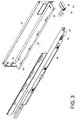
FIG. 3 is an exploded perspective view showing how the drawer frame member inFIG. 2 is mounted to the second rail of the slide assembly via an engaging member; -
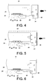
FIG. 4 is a plan view showing how the engaging member inFIG. 3 corresponds to an engaging portion of the second rail while the drawer frame member is being mounted to the second rail; -
FIG. 5 is a plan view showing how the second inclined surface of the leading second engaging block of the engaging member inFIG. 4 moves past the first inclined surface of the first-encountered first engaging block of the engaging portion while the drawer frame member is being mounted to the second rail; -
FIG. 6 is a plan view showing how the leading second engaging block of the engaging member inFIG. 5 interlocks with the first-encountered first engaging block of the engaging portion to fix the second rail and the drawer frame member to each other while the drawer frame member is being mounted to the second rail; -
FIG. 7 is a perspective view showing that the carrier inFIG. 2 has a pressing portion corresponding to a stop portion of the second rail; -
FIG. 8 is a perspective view showing the pressing portion of the carrier inFIG. 7 pressed against the stop portion of the second rail; -
FIG. 9 is a plan view showing how the pressing portion of the carrier of the drawer frame member inFIG. 7 is pressed against the stop portion of the second rail; -
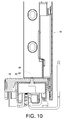
FIG. 10 is a sectional view ofFIG. 2 , showing how the engaging member is locked to the carrier of the drawer frame member by a screw and how the screw is fitted into a recess of the second rail; and -
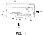
FIG. 11 schematically shows how an operating member is operated to disengage the engaging member inFIG. 6 from the engaging portion of the second rail. - Referring to
FIG. 1 , adrawer 10 is mounted to acabinet 14 via a pair ofslide assemblies 12. Theslide assemblies 12 allow thedrawer 10 to be pulled out of and pushed back into thecabinet 14. Thedrawer 10 includes a pair ofdrawer frame members 16, afront panel 18, arear panel 20, and abottom panel 22. Thedrawer frame members 16 are mounted on theslide assemblies 12 respectively to form a quick-release mechanism for drawer slide parts. -
FIG. 2 shows one of thedrawer frame members 16 mounted on thecorresponding slide assembly 12. As shown in the drawing, theslide assembly 12 includes afirst rail 24 and asecond rail 26 which can be displaced with respect to thefirst rail 24. Theslide assembly 12 further includes athird rail 28 movably connected between thefirst rail 24 and thesecond rail 26 in order to increase the distance by which thesecond rail 26 can be pulled out with respect to thefirst rail 24. Thedrawer frame member 16 is mounted on thesecond rail 26 via acarrier 30. - As shown in
FIG. 3 , thesecond rail 26 includes anengaging portion 32. In practice, theengaging portion 32 can be either a component attached to thesecond rail 26 or integrally formed with thesecond rail 26. Additionally, anengaging member 34 is mounted on thedrawer frame member 16 and corresponds to theengaging portion 32. More specifically, thecarrier 30 of thedrawer frame member 16 has afront portion 36 and arear portion 38 opposite thefront portion 36, and theengaging member 34 is mounted at thefront portion 36 of thecarrier 30. Theengaging member 34 is fixed to thefront portion 36 of thecarrier 30 by a fixing means 40 such as a screw. The fixing means 40 corresponds to arecess 42 in an end portion of thesecond rail 26. - As shown in
FIG. 4 to FIG. 6 , theengaging portion 32 includes a plurality of firstengaging blocks 44, and theengaging member 34 has abase 46 mounted on thecarrier 30, anelastic arm 48 extending from thebase 46, and a plurality of secondengaging blocks 50 on theelastic arm 48. Each firstengaging block 44 has a front end provided with a firstinclined surface 52 while each secondengaging block 50 has a front end provided with a secondinclined surface 54. To mount thecarrier 30 of thedrawer frame member 16 to thesecond rail 26, a portion of thecarrier 30 is put astride thesecond rail 26, and an external force F1 is applied to thecarrier 30 to move thecarrier 30 along thesecond rail 26 toward a mounting position. During the process, theengaging member 34 approaches theengaging portion 32 of thesecond rail 26 until the leading secondengaging block 50 of theengaging member 34 is pressed against the first-encountered firstengaging block 44 of theengaging portion 32. As application of the external force F1 continues, the secondinclined surface 54 of the leading secondengaging block 50 of theengaging member 34 pushes the firstinclined surface 52 of the first-encountered firstengaging block 44 such that theelastic arm 48 is forced aside, allowing the leading secondengaging block 50 to move past and interlock with the first-encountered firstengaging block 44. Consequently, thesecond rail 26 and thedrawer frame member 16 are fixed to each other. - Referring to
FIG. 7 to FIG. 9 , therear portion 38 of thecarrier 30 has apressing portion 56, thesecond rail 26 has astop portion 58, and thepressing portion 56 corresponds to thestop portion 58. When thecarrier 30 subjected to the external force F1 moved along thesecond rail 26 to the mounting position, thepressing portion 56 is pressed against and stopped by thestop portion 58. More specifically, thepressing portion 56 is a groove, and thestop portion 58 is a protruding stop plate. Once thecarrier 30 moves along thesecond rail 26 to the mounting position, the stop plate is fitted in the groove and thus fixed in place, as shown inFIG. 8 andFIG. 9 . After thedrawer frame member 16 is mounted to thesecond rail 26 via thecarrier 30, both thefront portion 36 and therear portion 38 of thecarrier 30 are securely fixed to thesecond rail 26. - Referring to
FIG. 10 , when thedrawer frame member 16 is mounted on thesecond rail 26, the fixing means 40 happens to fit in therecess 42 of thesecond rail 26 and is restrained in therecess 42, thereby preventing lateral vibrations caused by pulling or pushing the drawer 10 (seeFIG. 1 ) from disengaging the interlocked first and second engagingblocks 44 and 50 (seeFIG. 6 ). This technical feature lends enhanced stability to the mechanism of the present invention. - In addition, referring to
FIG. 11 , theelastic arm 48 of the engagingmember 34 has an operatingmember 60. When the drawer 10 (seeFIG. 1 ) needs to be pulled out in order to be cleaned or the like, the user can apply a lateral external force F2 to the operatingmember 60 singlehandedly, or more particularly with four fingers (i.e., excluding the thumb), to pull theelastic arm 48 open, thus separating the interlocked first and second engagingblocks drawer frame member 16 in the palm of the same hand, the user applies an external force F3 to thedrawer frame member 16 in a direction facing away from the mounting position, in order to move thecarrier 30 along thesecond rail 26 toward a pulled-out position, thereby separating thedrawer frame member 16 from thesecond rail 26. - The singlehanded detaching operation described above is made possible by the fact that the engaging
member 34 is mounted on thedrawer frame member 16. The present invention, therefore, provides convenience of operation by allowing the user to detach the drawer 10 (seeFIG. 1 ) from the left andright slide assemblies 12 with both hands simultaneously. - While the present invention has been disclosed by way of the foregoing preferred embodiment, the embodiment is not intended to be restrictive of the scope of the invention. The scope of patent protection sought by the applicant is defined by the appended claims.
Claims (9)
- A quick-release mechanism for drawer slide parts, comprising:a rail (26) and a drawer frame member (16),characterized inthat the rail (26) includes an engaging portion (32);that the drawer frame member (16) includes a carrier (30) mountable on the rail (26); andthat the quick-release mechanism further comprises an engaging member (34) mounted on the drawer frame member (16),wherein once the drawer frame member (16) is mounted on the rail (26), the engaging member (34) is engaged with the engaging portion (32) to fix the rail (26) and the drawer frame member (16) to each other.
- The quick-release mechanism as claimed in claim 1, further comprising another rail (24), wherein the rail (26) is displaceable with respect to said another rail (24).
- The quick-release mechanism as claimed in claim 1 or 2, wherein the carrier (30) has a front portion (36), and the engaging member (34) is mounted at the front portion (36) of the carrier (30).
- The quick-release mechanism as claimed in claim 3, wherein the carrier (30) has a rear portion (38) opposite the front portion (36), the rear portion (38) of the carrier (30) has a pressing portion (56), the rail (26) has a stop portion (58), and the pressing portion (56) is configured to be pressed against and stopped
- The quick-release mechanism as claimed in any one of claims 1-4, wherein the engaging portion (32) includes a plurality of first engaging blocks (44); the engaging member (34) has a base (46) mounted on the carrier (30), an elastic arm (48) extending from the base (46), and a plurality of second engaging blocks (50) on the elastic arm (48); and one of the first engaging blocks (44) interlocks with one of the second engaging blocks (50) to fix the second rail (26) and the drawer frame member (16) to each other.
- The quick-release mechanism as claimed in claim 1 or 2, wherein the rail (26) includes the engaging portion (32) and a stop portion (58), the engaging portion (32) of the rail (26) including a plurality of first engaging blocks (44); the drawer frame member (16) is mountable on the rail (26) via the carrier (30), the carrier (30) having a front portion (36) and a rear portion (38), the rear portion (38) of the carrier (30) having a pressing portion (56); the engaging member (34) includes a base (46) mounted on the carrier (30), an elastic arm (48) extending from the base (46), and a plurality of second engaging blocks (50) on the elastic arm (48); once the drawer frame member (16) is mounted on the second rail (26), one of the first engaging blocks (44) interlocks with one of the second engaging blocks (50), and the pressing portion (56) is pressed against the stop portion (58), thereby fixing the second rail (26) and the drawer frame member (16) to each other.
- The quick-release mechanism as claimed in any one of claims 1-6, wherein the engaging member (34) is fixed to the carrier (30) by a fixing means (40), the second rail (26) has an end portion provided with a recess (42), and the fixing means (40) is fitted in the recess (42).
- The quick-release mechanism as claimed in claim 5 or 6, wherein each said first engaging block (44) has a front end provided with a first inclined surface (52), each said second engaging block (50) has a front end provided with a second inclined surface (54), and the second inclined surface (54) of the one of the second engaging blocks (50) moves past the first inclined surface (52) of the one of the first engaging blocks (44) in order for the one of the first engaging blocks (44) to interlock with the one of the second engaging blocks (50).
- The quick-release mechanism for drawer slide parts as claimed in any one claims 5, 6, and 8, wherein the elastic arm (48) has an operating member (60) operable to disengage the one of the first engaging blocks (44) from the one of the second engaging blocks (50).
Applications Claiming Priority (1)
| Application Number | Priority Date | Filing Date | Title |
|---|---|---|---|
| TW104137458A TWI548370B (en) | 2015-11-12 | 2015-11-12 | Quick release mechanism for drawer slide parts |
Publications (2)
| Publication Number | Publication Date |
|---|---|
| EP3167756A1 true EP3167756A1 (en) | 2017-05-17 |
| EP3167756B1 EP3167756B1 (en) | 2019-11-20 |
Family
ID=56507419
Family Applications (1)
| Application Number | Title | Priority Date | Filing Date |
|---|---|---|---|
| EP16180290.5A Active EP3167756B1 (en) | 2015-11-12 | 2016-07-20 | Quick-release mechanism for drawer slide parts |
Country Status (4)
| Country | Link |
|---|---|
| US (1) | US9693627B2 (en) |
| EP (1) | EP3167756B1 (en) |
| JP (1) | JP6505053B2 (en) |
| TW (1) | TWI548370B (en) |
Cited By (2)
| Publication number | Priority date | Publication date | Assignee | Title |
|---|---|---|---|---|
| US11464333B2 (en) * | 2018-02-01 | 2022-10-11 | Julius Blum Gmbh | Loading rail for a pull-out guide for a drawer |
| WO2024016038A1 (en) | 2022-07-21 | 2024-01-25 | Julius Blum Gmbh | Assembly comprising at least one drawer pull-out guide |
Families Citing this family (13)
| Publication number | Priority date | Publication date | Assignee | Title |
|---|---|---|---|---|
| TWI548369B (en) * | 2015-10-06 | 2016-09-11 | King Slide Works Co Ltd | Mounting part for slide rail assembly |
| TWI568381B (en) * | 2015-12-21 | 2017-02-01 | 川湖科技股份有限公司 | Slide rail assembly and guiding mechanism thereof |
| USD838516S1 (en) * | 2016-11-30 | 2019-01-22 | Tal Klumeck | Safety drawer |
| TWI616164B (en) * | 2017-03-07 | 2018-03-01 | 川湖科技股份有限公司 | Coupling mechanism and slide rail assembly for furniture part |
| TWI616163B (en) * | 2017-03-07 | 2018-03-01 | 川湖科技股份有限公司 | Coupling mechanism and slide rail assembly for furniture part |
| AT17935U1 (en) * | 2017-08-17 | 2023-08-15 | Blum Gmbh Julius | drawer slide |
| US10314396B2 (en) * | 2017-09-27 | 2019-06-11 | Nan Juen International Co., Ltd. | Quick detachable slide rail and drawer mounting structure |
| TWI642387B (en) * | 2017-11-13 | 2018-12-01 | 川湖科技股份有限公司 | Slide rail rack system and carried object thereof |
| CN108151431A (en) * | 2017-12-31 | 2018-06-12 | 无锡海达尔精密滑轨股份有限公司 | A kind of mounting connection structure of sliding rail |
| US10499736B2 (en) * | 2018-03-29 | 2019-12-10 | Hardware Resources, Inc. | Apparatus and method for pullout cage mounting and adjustment |
| AT521105B1 (en) * | 2018-04-06 | 2023-11-15 | Blum Gmbh Julius | Drawer rail for a drawer pull-out guide |
| DE102018108647A1 (en) * | 2018-04-11 | 2019-10-17 | Paul Hettich Gmbh & Co. Kg | Pull-out guide and drawer series |
| CN111887628A (en) * | 2020-08-14 | 2020-11-06 | 广东东泰五金精密制造有限公司 | Integrated drawer side plate structure of optimizing |
Citations (3)
| Publication number | Priority date | Publication date | Assignee | Title |
|---|---|---|---|---|
| EP0421458A1 (en) * | 1989-10-06 | 1991-04-10 | Julius Blum Gesellschaft m.b.H. | Drawer |
| US8807672B2 (en) | 2011-05-05 | 2014-08-19 | Julius Blum Gmbh | Drawer pull-out guide element |
| US20140314347A1 (en) * | 2012-12-12 | 2014-10-23 | Nan Juen International Co., Ltd. | Adjustable coupling device for connection between a sliding rail assembly and a sliding box |
Family Cites Families (17)
| Publication number | Priority date | Publication date | Assignee | Title |
|---|---|---|---|---|
| JPS5820562U (en) * | 1981-07-30 | 1983-02-08 | 株式会社東芝 | Structure to prevent case mounting screws from falling off |
| DE8431503U1 (en) * | 1984-10-26 | 1985-01-31 | Paul Hettich GmbH & Co, 4983 Kirchlengern | DRAWER |
| JP3470630B2 (en) * | 1999-02-26 | 2003-11-25 | コクヨ株式会社 | Drawer mounting structure |
| DE19944640A1 (en) * | 1999-09-17 | 2001-03-22 | Hettich Paul Gmbh & Co | Pull-out guide set |
| ATE526850T1 (en) * | 2003-05-13 | 2011-10-15 | Grass Gmbh | FRONTAL LOCKING DEVICE FOR REleasably engaging a drawer in a drawer slide |
| DE202006006065U1 (en) * | 2006-04-13 | 2007-08-23 | Alfit Ag | Underfloor guide arrangement for furniture parts, in particular in the body of furniture |
| TWI326590B (en) * | 2007-05-15 | 2010-07-01 | King Slide Works Co Ltd | Fixing device for a drawer slide |
| US7695080B2 (en) | 2007-06-05 | 2010-04-13 | King Slide Works Co., Ltd. | Securing device for a drawer slide |
| TWI346532B (en) * | 2008-03-21 | 2011-08-11 | King Slide Works Co Ltd | Slide adjusting device for use in a drawer |
| TW200944157A (en) | 2008-04-18 | 2009-11-01 | King Slide Works Co Ltd | Positioning device for a drawer with a drawer slide |
| AT506879B1 (en) * | 2008-06-10 | 2011-07-15 | Blum Gmbh Julius | DEVICE FOR RELEASABLE DUPLICATION OF A DRAWER WITH A RAIL OF A DRAWER EXTRACTOR |
| DE102010017639A1 (en) * | 2010-06-29 | 2011-12-29 | Paul Hettich Gmbh & Co. Kg | Cupboard furniture with a pull-out part |
| AT510777B1 (en) * | 2010-11-23 | 2014-06-15 | Blum Gmbh Julius | COUPLING DEVICE FOR DRAWERS |
| JP5299501B2 (en) * | 2011-12-27 | 2013-09-25 | 住友電装株式会社 | Automotive electrical equipment group |
| DE202013004939U1 (en) * | 2013-05-29 | 2014-09-03 | Grass Gmbh | Device for positioning and fixing a movable furniture part |
| AT14476U1 (en) * | 2014-02-13 | 2015-11-15 | Blum Gmbh Julius | Pull-out guide for a movable furniture part |
| DE102014104136A1 (en) * | 2014-03-25 | 2015-10-01 | Paul Hettich Gmbh & Co. Kg | Pull-out guide for a drawer and method for attaching a drawer to a drawer slide |
-
2015
- 2015-11-12 TW TW104137458A patent/TWI548370B/en active
-
2016
- 2016-07-06 US US15/202,815 patent/US9693627B2/en active Active
- 2016-07-20 EP EP16180290.5A patent/EP3167756B1/en active Active
- 2016-07-21 JP JP2016143458A patent/JP6505053B2/en active Active
Patent Citations (3)
| Publication number | Priority date | Publication date | Assignee | Title |
|---|---|---|---|---|
| EP0421458A1 (en) * | 1989-10-06 | 1991-04-10 | Julius Blum Gesellschaft m.b.H. | Drawer |
| US8807672B2 (en) | 2011-05-05 | 2014-08-19 | Julius Blum Gmbh | Drawer pull-out guide element |
| US20140314347A1 (en) * | 2012-12-12 | 2014-10-23 | Nan Juen International Co., Ltd. | Adjustable coupling device for connection between a sliding rail assembly and a sliding box |
Non-Patent Citations (2)
| Title |
|---|
| NAN JUEN INTERNATIONAL CO LTD: "Wooden drawer slides NJ-A5601 - Quick-realease", 13 August 2013 (2013-08-13), www.repon.com.tw, XP055348499, Retrieved from the Internet <URL:http://www.repon.com.tw/pd_search2013/download/nja5601.pdf> [retrieved on 20170222] * |
| NAN JUEN INTERNATIONAL CO LTD: "Wooden drawer slides NJ-A5A02 - Quick-release & side/vertical adjustment", 20 December 2013 (2013-12-20), www.repon.com.tw, XP055348583, Retrieved from the Internet <URL:http://web.archive.org/save/_embed/http://www.repon.com.tw/pd_search2013/download/nja5a02.pdf> [retrieved on 20170222] * |
Cited By (4)
| Publication number | Priority date | Publication date | Assignee | Title |
|---|---|---|---|---|
| US11464333B2 (en) * | 2018-02-01 | 2022-10-11 | Julius Blum Gmbh | Loading rail for a pull-out guide for a drawer |
| WO2024016038A1 (en) | 2022-07-21 | 2024-01-25 | Julius Blum Gmbh | Assembly comprising at least one drawer pull-out guide |
| AT526385A1 (en) * | 2022-07-21 | 2024-02-15 | Blum Gmbh Julius | Arrangement with at least one drawer pull-out guide |
| EP4714299A2 (en) | 2022-07-21 | 2026-03-25 | Julius Blum GmbH | Arrangement with at least one drawer pull-out guide |
Also Published As
| Publication number | Publication date |
|---|---|
| TW201716002A (en) | 2017-05-16 |
| JP2017086865A (en) | 2017-05-25 |
| EP3167756B1 (en) | 2019-11-20 |
| TWI548370B (en) | 2016-09-11 |
| JP6505053B2 (en) | 2019-04-24 |
| US20170135476A1 (en) | 2017-05-18 |
| US9693627B2 (en) | 2017-07-04 |
Similar Documents
| Publication | Publication Date | Title |
|---|---|---|
| EP3167756B1 (en) | Quick-release mechanism for drawer slide parts | |
| EP3153065B1 (en) | Mounting part for slide rail assembly | |
| US8146756B2 (en) | Universal toolless rack mount bracket | |
| EP3148304B1 (en) | Slide rail assembly and bracket device thereof | |
| US9918404B1 (en) | Server sliding rail mounting bracket assembly | |
| JP5410851B2 (en) | Guide rail fixing device | |
| US10123616B2 (en) | Tall cabinet quick release structure | |
| TWI598024B (en) | Slide rail assembly and bracket thereof | |
| EP3398481B1 (en) | Slide rail assembly | |
| US6456501B1 (en) | Quick release mechanism for sliding rail | |
| EP3378353B1 (en) | Synchronization system for slide rail assembly | |
| US20160198855A1 (en) | Slide rail assembly and mounting device thereof | |
| TWI631557B (en) | Quick-releasing mechanism and related electronic apparatus | |
| GB2490983A (en) | Slide assembly with locking mechanism | |
| US20150137673A1 (en) | Securing mechanism | |
| US7658457B2 (en) | Inner sliding rail mounting structure for sliding track assembly for drawer | |
| TWM498443U (en) | Quick release fixing mechanism and related electronic device | |
| EP3041328B1 (en) | Slide rail assembly | |
| TW201442670A (en) | Sliding rail | |
| US9755687B2 (en) | Housing mounting mechanism for portable electronic device | |
| EP3045074A1 (en) | Slide rail assembly and mounting device thereof | |
| RU2646962C1 (en) | Device for automatic chassis unlocking | |
| US8724305B2 (en) | Electronic device with quick-release supporting apparatus | |
| CN106820680B (en) | Quick-dismantling slide rail assembly | |
| CN215126769U (en) | Fastener device capable of releasing object to be fixed |
Legal Events
| Date | Code | Title | Description |
|---|---|---|---|
| PUAI | Public reference made under article 153(3) epc to a published international application that has entered the european phase |
Free format text: ORIGINAL CODE: 0009012 |
|
| STAA | Information on the status of an ep patent application or granted ep patent |
Free format text: STATUS: THE APPLICATION HAS BEEN PUBLISHED |
|
| AK | Designated contracting states |
Kind code of ref document: A1 Designated state(s): AL AT BE BG CH CY CZ DE DK EE ES FI FR GB GR HR HU IE IS IT LI LT LU LV MC MK MT NL NO PL PT RO RS SE SI SK SM TR |
|
| AX | Request for extension of the european patent |
Extension state: BA ME |
|
| STAA | Information on the status of an ep patent application or granted ep patent |
Free format text: STATUS: REQUEST FOR EXAMINATION WAS MADE |
|
| 17P | Request for examination filed |
Effective date: 20170720 |
|
| RBV | Designated contracting states (corrected) |
Designated state(s): AL AT BE BG CH CY CZ DE DK EE ES FI FR GB GR HR HU IE IS IT LI LT LU LV MC MK MT NL NO PL PT RO RS SE SI SK SM TR |
|
| STAA | Information on the status of an ep patent application or granted ep patent |
Free format text: STATUS: EXAMINATION IS IN PROGRESS |
|
| 17Q | First examination report despatched |
Effective date: 20180111 |
|
| GRAP | Despatch of communication of intention to grant a patent |
Free format text: ORIGINAL CODE: EPIDOSNIGR1 |
|
| STAA | Information on the status of an ep patent application or granted ep patent |
Free format text: STATUS: GRANT OF PATENT IS INTENDED |
|
| INTG | Intention to grant announced |
Effective date: 20190613 |
|
| RAP1 | Party data changed (applicant data changed or rights of an application transferred) |
Owner name: KING SLIDE TECHNOLOGY CO., LTD. Owner name: KING SLIDE WORKS CO., LTD. |
|
| RIN1 | Information on inventor provided before grant (corrected) |
Inventor name: CHEN, KEN-CHING Inventor name: SU, FANG-CHENG Inventor name: HUANG, CI-BIN Inventor name: LIANG, HSIU-CHIANG Inventor name: WANG, CHUN-CHIANG |
|
| GRAS | Grant fee paid |
Free format text: ORIGINAL CODE: EPIDOSNIGR3 |
|
| GRAA | (expected) grant |
Free format text: ORIGINAL CODE: 0009210 |
|
| STAA | Information on the status of an ep patent application or granted ep patent |
Free format text: STATUS: THE PATENT HAS BEEN GRANTED |
|
| AK | Designated contracting states |
Kind code of ref document: B1 Designated state(s): AL AT BE BG CH CY CZ DE DK EE ES FI FR GB GR HR HU IE IS IT LI LT LU LV MC MK MT NL NO PL PT RO RS SE SI SK SM TR |
|
| REG | Reference to a national code |
Ref country code: GB Ref legal event code: FG4D |
|
| REG | Reference to a national code |
Ref country code: CH Ref legal event code: EP |
|
| REG | Reference to a national code |
Ref country code: IE Ref legal event code: FG4D |
|
| REG | Reference to a national code |
Ref country code: DE Ref legal event code: R096 Ref document number: 602016024557 Country of ref document: DE |
|
| REG | Reference to a national code |
Ref country code: AT Ref legal event code: REF Ref document number: 1203173 Country of ref document: AT Kind code of ref document: T Effective date: 20191215 |
|
| REG | Reference to a national code |
Ref country code: NL Ref legal event code: MP Effective date: 20191120 |
|
| REG | Reference to a national code |
Ref country code: LT Ref legal event code: MG4D |
|
| PG25 | Lapsed in a contracting state [announced via postgrant information from national office to epo] |
Ref country code: NL Free format text: LAPSE BECAUSE OF FAILURE TO SUBMIT A TRANSLATION OF THE DESCRIPTION OR TO PAY THE FEE WITHIN THE PRESCRIBED TIME-LIMIT Effective date: 20191120 Ref country code: GR Free format text: LAPSE BECAUSE OF FAILURE TO SUBMIT A TRANSLATION OF THE DESCRIPTION OR TO PAY THE FEE WITHIN THE PRESCRIBED TIME-LIMIT Effective date: 20200221 Ref country code: LT Free format text: LAPSE BECAUSE OF FAILURE TO SUBMIT A TRANSLATION OF THE DESCRIPTION OR TO PAY THE FEE WITHIN THE PRESCRIBED TIME-LIMIT Effective date: 20191120 Ref country code: FI Free format text: LAPSE BECAUSE OF FAILURE TO SUBMIT A TRANSLATION OF THE DESCRIPTION OR TO PAY THE FEE WITHIN THE PRESCRIBED TIME-LIMIT Effective date: 20191120 Ref country code: BG Free format text: LAPSE BECAUSE OF FAILURE TO SUBMIT A TRANSLATION OF THE DESCRIPTION OR TO PAY THE FEE WITHIN THE PRESCRIBED TIME-LIMIT Effective date: 20200220 Ref country code: NO Free format text: LAPSE BECAUSE OF FAILURE TO SUBMIT A TRANSLATION OF THE DESCRIPTION OR TO PAY THE FEE WITHIN THE PRESCRIBED TIME-LIMIT Effective date: 20200220 Ref country code: LV Free format text: LAPSE BECAUSE OF FAILURE TO SUBMIT A TRANSLATION OF THE DESCRIPTION OR TO PAY THE FEE WITHIN THE PRESCRIBED TIME-LIMIT Effective date: 20191120 Ref country code: SE Free format text: LAPSE BECAUSE OF FAILURE TO SUBMIT A TRANSLATION OF THE DESCRIPTION OR TO PAY THE FEE WITHIN THE PRESCRIBED TIME-LIMIT Effective date: 20191120 |
|
| PG25 | Lapsed in a contracting state [announced via postgrant information from national office to epo] |
Ref country code: IS Free format text: LAPSE BECAUSE OF FAILURE TO SUBMIT A TRANSLATION OF THE DESCRIPTION OR TO PAY THE FEE WITHIN THE PRESCRIBED TIME-LIMIT Effective date: 20200320 Ref country code: HR Free format text: LAPSE BECAUSE OF FAILURE TO SUBMIT A TRANSLATION OF THE DESCRIPTION OR TO PAY THE FEE WITHIN THE PRESCRIBED TIME-LIMIT Effective date: 20191120 Ref country code: RS Free format text: LAPSE BECAUSE OF FAILURE TO SUBMIT A TRANSLATION OF THE DESCRIPTION OR TO PAY THE FEE WITHIN THE PRESCRIBED TIME-LIMIT Effective date: 20191120 |
|
| PG25 | Lapsed in a contracting state [announced via postgrant information from national office to epo] |
Ref country code: AL Free format text: LAPSE BECAUSE OF FAILURE TO SUBMIT A TRANSLATION OF THE DESCRIPTION OR TO PAY THE FEE WITHIN THE PRESCRIBED TIME-LIMIT Effective date: 20191120 |
|
| PG25 | Lapsed in a contracting state [announced via postgrant information from national office to epo] |
Ref country code: RO Free format text: LAPSE BECAUSE OF FAILURE TO SUBMIT A TRANSLATION OF THE DESCRIPTION OR TO PAY THE FEE WITHIN THE PRESCRIBED TIME-LIMIT Effective date: 20191120 Ref country code: CZ Free format text: LAPSE BECAUSE OF FAILURE TO SUBMIT A TRANSLATION OF THE DESCRIPTION OR TO PAY THE FEE WITHIN THE PRESCRIBED TIME-LIMIT Effective date: 20191120 Ref country code: EE Free format text: LAPSE BECAUSE OF FAILURE TO SUBMIT A TRANSLATION OF THE DESCRIPTION OR TO PAY THE FEE WITHIN THE PRESCRIBED TIME-LIMIT Effective date: 20191120 Ref country code: PT Free format text: LAPSE BECAUSE OF FAILURE TO SUBMIT A TRANSLATION OF THE DESCRIPTION OR TO PAY THE FEE WITHIN THE PRESCRIBED TIME-LIMIT Effective date: 20200412 Ref country code: DK Free format text: LAPSE BECAUSE OF FAILURE TO SUBMIT A TRANSLATION OF THE DESCRIPTION OR TO PAY THE FEE WITHIN THE PRESCRIBED TIME-LIMIT Effective date: 20191120 Ref country code: ES Free format text: LAPSE BECAUSE OF FAILURE TO SUBMIT A TRANSLATION OF THE DESCRIPTION OR TO PAY THE FEE WITHIN THE PRESCRIBED TIME-LIMIT Effective date: 20191120 |
|
| REG | Reference to a national code |
Ref country code: AT Ref legal event code: MK05 Ref document number: 1203173 Country of ref document: AT Kind code of ref document: T Effective date: 20191120 |
|
| REG | Reference to a national code |
Ref country code: DE Ref legal event code: R097 Ref document number: 602016024557 Country of ref document: DE |
|
| PG25 | Lapsed in a contracting state [announced via postgrant information from national office to epo] |
Ref country code: SM Free format text: LAPSE BECAUSE OF FAILURE TO SUBMIT A TRANSLATION OF THE DESCRIPTION OR TO PAY THE FEE WITHIN THE PRESCRIBED TIME-LIMIT Effective date: 20191120 Ref country code: SK Free format text: LAPSE BECAUSE OF FAILURE TO SUBMIT A TRANSLATION OF THE DESCRIPTION OR TO PAY THE FEE WITHIN THE PRESCRIBED TIME-LIMIT Effective date: 20191120 |
|
| PLBE | No opposition filed within time limit |
Free format text: ORIGINAL CODE: 0009261 |
|
| STAA | Information on the status of an ep patent application or granted ep patent |
Free format text: STATUS: NO OPPOSITION FILED WITHIN TIME LIMIT |
|
| 26N | No opposition filed |
Effective date: 20200821 |
|
| PG25 | Lapsed in a contracting state [announced via postgrant information from national office to epo] |
Ref country code: AT Free format text: LAPSE BECAUSE OF FAILURE TO SUBMIT A TRANSLATION OF THE DESCRIPTION OR TO PAY THE FEE WITHIN THE PRESCRIBED TIME-LIMIT Effective date: 20191120 Ref country code: PL Free format text: LAPSE BECAUSE OF FAILURE TO SUBMIT A TRANSLATION OF THE DESCRIPTION OR TO PAY THE FEE WITHIN THE PRESCRIBED TIME-LIMIT Effective date: 20191120 Ref country code: SI Free format text: LAPSE BECAUSE OF FAILURE TO SUBMIT A TRANSLATION OF THE DESCRIPTION OR TO PAY THE FEE WITHIN THE PRESCRIBED TIME-LIMIT Effective date: 20191120 |
|
| PG25 | Lapsed in a contracting state [announced via postgrant information from national office to epo] |
Ref country code: IT Free format text: LAPSE BECAUSE OF FAILURE TO SUBMIT A TRANSLATION OF THE DESCRIPTION OR TO PAY THE FEE WITHIN THE PRESCRIBED TIME-LIMIT Effective date: 20191120 |
|
| PG25 | Lapsed in a contracting state [announced via postgrant information from national office to epo] |
Ref country code: MC Free format text: LAPSE BECAUSE OF FAILURE TO SUBMIT A TRANSLATION OF THE DESCRIPTION OR TO PAY THE FEE WITHIN THE PRESCRIBED TIME-LIMIT Effective date: 20191120 |
|
| REG | Reference to a national code |
Ref country code: CH Ref legal event code: PL |
|
| REG | Reference to a national code |
Ref country code: BE Ref legal event code: MM Effective date: 20200731 |
|
| PG25 | Lapsed in a contracting state [announced via postgrant information from national office to epo] |
Ref country code: FR Free format text: LAPSE BECAUSE OF NON-PAYMENT OF DUE FEES Effective date: 20200731 Ref country code: LI Free format text: LAPSE BECAUSE OF NON-PAYMENT OF DUE FEES Effective date: 20200731 Ref country code: LU Free format text: LAPSE BECAUSE OF NON-PAYMENT OF DUE FEES Effective date: 20200720 Ref country code: CH Free format text: LAPSE BECAUSE OF NON-PAYMENT OF DUE FEES Effective date: 20200731 |
|
| PG25 | Lapsed in a contracting state [announced via postgrant information from national office to epo] |
Ref country code: BE Free format text: LAPSE BECAUSE OF NON-PAYMENT OF DUE FEES Effective date: 20200731 |
|
| PG25 | Lapsed in a contracting state [announced via postgrant information from national office to epo] |
Ref country code: TR Free format text: LAPSE BECAUSE OF FAILURE TO SUBMIT A TRANSLATION OF THE DESCRIPTION OR TO PAY THE FEE WITHIN THE PRESCRIBED TIME-LIMIT Effective date: 20191120 Ref country code: MT Free format text: LAPSE BECAUSE OF FAILURE TO SUBMIT A TRANSLATION OF THE DESCRIPTION OR TO PAY THE FEE WITHIN THE PRESCRIBED TIME-LIMIT Effective date: 20191120 Ref country code: CY Free format text: LAPSE BECAUSE OF FAILURE TO SUBMIT A TRANSLATION OF THE DESCRIPTION OR TO PAY THE FEE WITHIN THE PRESCRIBED TIME-LIMIT Effective date: 20191120 |
|
| PG25 | Lapsed in a contracting state [announced via postgrant information from national office to epo] |
Ref country code: MK Free format text: LAPSE BECAUSE OF FAILURE TO SUBMIT A TRANSLATION OF THE DESCRIPTION OR TO PAY THE FEE WITHIN THE PRESCRIBED TIME-LIMIT Effective date: 20191120 |
|
| PGFP | Annual fee paid to national office [announced via postgrant information from national office to epo] |
Ref country code: GB Payment date: 20250508 Year of fee payment: 10 |
|
| PGFP | Annual fee paid to national office [announced via postgrant information from national office to epo] |
Ref country code: IE Payment date: 20250507 Year of fee payment: 10 |
|
| PGFP | Annual fee paid to national office [announced via postgrant information from national office to epo] |
Ref country code: DE Payment date: 20250512 Year of fee payment: 10 |