EP3167532B1 - Resonatorausgleich in systemen zur drahtlosen stromübertragung - Google Patents
Resonatorausgleich in systemen zur drahtlosen stromübertragung Download PDFInfo
- Publication number
- EP3167532B1 EP3167532B1 EP15738810.9A EP15738810A EP3167532B1 EP 3167532 B1 EP3167532 B1 EP 3167532B1 EP 15738810 A EP15738810 A EP 15738810A EP 3167532 B1 EP3167532 B1 EP 3167532B1
- Authority
- EP
- European Patent Office
- Prior art keywords
- windings
- inductance
- resonator
- winding
- coil
- Prior art date
- Legal status (The legal status is an assumption and is not a legal conclusion. Google has not performed a legal analysis and makes no representation as to the accuracy of the status listed.)
- Active
Links
- 238000012546 transfer Methods 0.000 title claims description 88
- 238000004804 winding Methods 0.000 claims description 357
- 238000005259 measurement Methods 0.000 claims description 63
- 239000011159 matrix material Substances 0.000 claims description 49
- 238000000034 method Methods 0.000 claims description 41
- 238000009826 distribution Methods 0.000 claims description 30
- 239000004020 conductor Substances 0.000 claims description 17
- 230000004048 modification Effects 0.000 claims description 12
- 238000012986 modification Methods 0.000 claims description 12
- 238000000638 solvent extraction Methods 0.000 claims description 9
- 230000008878 coupling Effects 0.000 description 88
- 238000010168 coupling process Methods 0.000 description 88
- 238000005859 coupling reaction Methods 0.000 description 88
- 230000006870 function Effects 0.000 description 76
- 239000003990 capacitor Substances 0.000 description 70
- 238000010586 diagram Methods 0.000 description 48
- XAGFODPZIPBFFR-UHFFFAOYSA-N aluminium Chemical compound [Al] XAGFODPZIPBFFR-UHFFFAOYSA-N 0.000 description 34
- 229910052782 aluminium Inorganic materials 0.000 description 34
- 229910000859 α-Fe Inorganic materials 0.000 description 27
- 238000006073 displacement reaction Methods 0.000 description 26
- 239000000696 magnetic material Substances 0.000 description 21
- 238000004519 manufacturing process Methods 0.000 description 11
- 238000005457 optimization Methods 0.000 description 10
- 229910000831 Steel Inorganic materials 0.000 description 9
- 239000010959 steel Substances 0.000 description 9
- 230000000694 effects Effects 0.000 description 7
- 238000003860 storage Methods 0.000 description 7
- 239000000463 material Substances 0.000 description 6
- 229910052727 yttrium Inorganic materials 0.000 description 6
- 238000006243 chemical reaction Methods 0.000 description 5
- 238000004891 communication Methods 0.000 description 5
- 238000004590 computer program Methods 0.000 description 4
- 230000001939 inductive effect Effects 0.000 description 4
- WJZHMLNIAZSFDO-UHFFFAOYSA-N manganese zinc Chemical compound [Mn].[Zn] WJZHMLNIAZSFDO-UHFFFAOYSA-N 0.000 description 4
- QELJHCBNGDEXLD-UHFFFAOYSA-N nickel zinc Chemical compound [Ni].[Zn] QELJHCBNGDEXLD-UHFFFAOYSA-N 0.000 description 4
- RYGMFSIKBFXOCR-UHFFFAOYSA-N Copper Chemical compound [Cu] RYGMFSIKBFXOCR-UHFFFAOYSA-N 0.000 description 3
- 229910052802 copper Inorganic materials 0.000 description 3
- 239000010949 copper Substances 0.000 description 3
- 230000004907 flux Effects 0.000 description 3
- 230000006698 induction Effects 0.000 description 3
- 230000008569 process Effects 0.000 description 3
- 239000007787 solid Substances 0.000 description 3
- XEEYBQQBJWHFJM-UHFFFAOYSA-N Iron Chemical compound [Fe] XEEYBQQBJWHFJM-UHFFFAOYSA-N 0.000 description 2
- PXHVJJICTQNCMI-UHFFFAOYSA-N Nickel Chemical compound [Ni] PXHVJJICTQNCMI-UHFFFAOYSA-N 0.000 description 2
- BQCADISMDOOEFD-UHFFFAOYSA-N Silver Chemical compound [Ag] BQCADISMDOOEFD-UHFFFAOYSA-N 0.000 description 2
- 230000008901 benefit Effects 0.000 description 2
- 238000009529 body temperature measurement Methods 0.000 description 2
- 239000000919 ceramic Substances 0.000 description 2
- 238000013461 design Methods 0.000 description 2
- PCHJSUWPFVWCPO-UHFFFAOYSA-N gold Chemical compound [Au] PCHJSUWPFVWCPO-UHFFFAOYSA-N 0.000 description 2
- 229910052737 gold Inorganic materials 0.000 description 2
- 239000010931 gold Substances 0.000 description 2
- 230000017525 heat dissipation Effects 0.000 description 2
- 230000001965 increasing effect Effects 0.000 description 2
- 238000012544 monitoring process Methods 0.000 description 2
- 230000003287 optical effect Effects 0.000 description 2
- 230000004044 response Effects 0.000 description 2
- 229910052709 silver Inorganic materials 0.000 description 2
- 239000004332 silver Substances 0.000 description 2
- 229920006362 Teflon® Polymers 0.000 description 1
- 230000001594 aberrant effect Effects 0.000 description 1
- 239000000853 adhesive Substances 0.000 description 1
- 230000001070 adhesive effect Effects 0.000 description 1
- 238000013459 approach Methods 0.000 description 1
- 238000003491 array Methods 0.000 description 1
- 230000005540 biological transmission Effects 0.000 description 1
- 239000003985 ceramic capacitor Substances 0.000 description 1
- 230000008859 change Effects 0.000 description 1
- 230000000295 complement effect Effects 0.000 description 1
- PMHQVHHXPFUNSP-UHFFFAOYSA-M copper(1+);methylsulfanylmethane;bromide Chemical compound Br[Cu].CSC PMHQVHHXPFUNSP-UHFFFAOYSA-M 0.000 description 1
- 238000006880 cross-coupling reaction Methods 0.000 description 1
- 238000013500 data storage Methods 0.000 description 1
- 230000003247 decreasing effect Effects 0.000 description 1
- 239000003989 dielectric material Substances 0.000 description 1
- 239000012777 electrically insulating material Substances 0.000 description 1
- 230000014509 gene expression Effects 0.000 description 1
- 231100001261 hazardous Toxicity 0.000 description 1
- 238000010438 heat treatment Methods 0.000 description 1
- 229910052742 iron Inorganic materials 0.000 description 1
- 239000004973 liquid crystal related substance Substances 0.000 description 1
- 230000007246 mechanism Effects 0.000 description 1
- 230000000116 mitigating effect Effects 0.000 description 1
- 229910052759 nickel Inorganic materials 0.000 description 1
- 230000010355 oscillation Effects 0.000 description 1
- 238000013021 overheating Methods 0.000 description 1
- TWNQGVIAIRXVLR-UHFFFAOYSA-N oxo(oxoalumanyloxy)alumane Chemical compound O=[Al]O[Al]=O TWNQGVIAIRXVLR-UHFFFAOYSA-N 0.000 description 1
- 238000005192 partition Methods 0.000 description 1
- 230000035699 permeability Effects 0.000 description 1
- 239000004033 plastic Substances 0.000 description 1
- 238000012545 processing Methods 0.000 description 1
- 230000009466 transformation Effects 0.000 description 1
- 230000000007 visual effect Effects 0.000 description 1
Images


Classifications
-
- H—ELECTRICITY
- H02—GENERATION; CONVERSION OR DISTRIBUTION OF ELECTRIC POWER
- H02J—CIRCUIT ARRANGEMENTS OR SYSTEMS FOR SUPPLYING OR DISTRIBUTING ELECTRIC POWER; SYSTEMS FOR STORING ELECTRIC ENERGY
- H02J50/00—Circuit arrangements or systems for wireless supply or distribution of electric power
- H02J50/10—Circuit arrangements or systems for wireless supply or distribution of electric power using inductive coupling
- H02J50/12—Circuit arrangements or systems for wireless supply or distribution of electric power using inductive coupling of the resonant type
-
- H—ELECTRICITY
- H01—ELECTRIC ELEMENTS
- H01F—MAGNETS; INDUCTANCES; TRANSFORMERS; SELECTION OF MATERIALS FOR THEIR MAGNETIC PROPERTIES
- H01F38/00—Adaptations of transformers or inductances for specific applications or functions
- H01F38/14—Inductive couplings
-
- B—PERFORMING OPERATIONS; TRANSPORTING
- B60—VEHICLES IN GENERAL
- B60L—PROPULSION OF ELECTRICALLY-PROPELLED VEHICLES; SUPPLYING ELECTRIC POWER FOR AUXILIARY EQUIPMENT OF ELECTRICALLY-PROPELLED VEHICLES; ELECTRODYNAMIC BRAKE SYSTEMS FOR VEHICLES IN GENERAL; MAGNETIC SUSPENSION OR LEVITATION FOR VEHICLES; MONITORING OPERATING VARIABLES OF ELECTRICALLY-PROPELLED VEHICLES; ELECTRIC SAFETY DEVICES FOR ELECTRICALLY-PROPELLED VEHICLES
- B60L53/00—Methods of charging batteries, specially adapted for electric vehicles; Charging stations or on-board charging equipment therefor; Exchange of energy storage elements in electric vehicles
- B60L53/10—Methods of charging batteries, specially adapted for electric vehicles; Charging stations or on-board charging equipment therefor; Exchange of energy storage elements in electric vehicles characterised by the energy transfer between the charging station and the vehicle
- B60L53/12—Inductive energy transfer
- B60L53/122—Circuits or methods for driving the primary coil, e.g. supplying electric power to the coil
-
- B—PERFORMING OPERATIONS; TRANSPORTING
- B60—VEHICLES IN GENERAL
- B60L—PROPULSION OF ELECTRICALLY-PROPELLED VEHICLES; SUPPLYING ELECTRIC POWER FOR AUXILIARY EQUIPMENT OF ELECTRICALLY-PROPELLED VEHICLES; ELECTRODYNAMIC BRAKE SYSTEMS FOR VEHICLES IN GENERAL; MAGNETIC SUSPENSION OR LEVITATION FOR VEHICLES; MONITORING OPERATING VARIABLES OF ELECTRICALLY-PROPELLED VEHICLES; ELECTRIC SAFETY DEVICES FOR ELECTRICALLY-PROPELLED VEHICLES
- B60L53/00—Methods of charging batteries, specially adapted for electric vehicles; Charging stations or on-board charging equipment therefor; Exchange of energy storage elements in electric vehicles
- B60L53/10—Methods of charging batteries, specially adapted for electric vehicles; Charging stations or on-board charging equipment therefor; Exchange of energy storage elements in electric vehicles characterised by the energy transfer between the charging station and the vehicle
- B60L53/12—Inductive energy transfer
- B60L53/126—Methods for pairing a vehicle and a charging station, e.g. establishing a one-to-one relation between a wireless power transmitter and a wireless power receiver
-
- H—ELECTRICITY
- H01—ELECTRIC ELEMENTS
- H01F—MAGNETS; INDUCTANCES; TRANSFORMERS; SELECTION OF MATERIALS FOR THEIR MAGNETIC PROPERTIES
- H01F27/00—Details of transformers or inductances, in general
- H01F27/28—Coils; Windings; Conductive connections
- H01F27/2871—Pancake coils
-
- H02J5/005—
-
- H—ELECTRICITY
- H02—GENERATION; CONVERSION OR DISTRIBUTION OF ELECTRIC POWER
- H02J—CIRCUIT ARRANGEMENTS OR SYSTEMS FOR SUPPLYING OR DISTRIBUTING ELECTRIC POWER; SYSTEMS FOR STORING ELECTRIC ENERGY
- H02J50/00—Circuit arrangements or systems for wireless supply or distribution of electric power
- H02J50/005—Mechanical details of housing or structure aiming to accommodate the power transfer means, e.g. mechanical integration of coils, antennas or transducers into emitting or receiving devices
-
- H—ELECTRICITY
- H02—GENERATION; CONVERSION OR DISTRIBUTION OF ELECTRIC POWER
- H02J—CIRCUIT ARRANGEMENTS OR SYSTEMS FOR SUPPLYING OR DISTRIBUTING ELECTRIC POWER; SYSTEMS FOR STORING ELECTRIC ENERGY
- H02J50/00—Circuit arrangements or systems for wireless supply or distribution of electric power
- H02J50/70—Circuit arrangements or systems for wireless supply or distribution of electric power involving the reduction of electric, magnetic or electromagnetic leakage fields
-
- H—ELECTRICITY
- H02—GENERATION; CONVERSION OR DISTRIBUTION OF ELECTRIC POWER
- H02J—CIRCUIT ARRANGEMENTS OR SYSTEMS FOR SUPPLYING OR DISTRIBUTING ELECTRIC POWER; SYSTEMS FOR STORING ELECTRIC ENERGY
- H02J50/00—Circuit arrangements or systems for wireless supply or distribution of electric power
- H02J50/80—Circuit arrangements or systems for wireless supply or distribution of electric power involving the exchange of data, concerning supply or distribution of electric power, between transmitting devices and receiving devices
-
- H—ELECTRICITY
- H02—GENERATION; CONVERSION OR DISTRIBUTION OF ELECTRIC POWER
- H02J—CIRCUIT ARRANGEMENTS OR SYSTEMS FOR SUPPLYING OR DISTRIBUTING ELECTRIC POWER; SYSTEMS FOR STORING ELECTRIC ENERGY
- H02J7/00—Circuit arrangements for charging or depolarising batteries or for supplying loads from batteries
- H02J7/0029—Circuit arrangements for charging or depolarising batteries or for supplying loads from batteries with safety or protection devices or circuits
- H02J7/00309—Overheat or overtemperature protection
-
- H02J7/025—
-
- B—PERFORMING OPERATIONS; TRANSPORTING
- B60—VEHICLES IN GENERAL
- B60L—PROPULSION OF ELECTRICALLY-PROPELLED VEHICLES; SUPPLYING ELECTRIC POWER FOR AUXILIARY EQUIPMENT OF ELECTRICALLY-PROPELLED VEHICLES; ELECTRODYNAMIC BRAKE SYSTEMS FOR VEHICLES IN GENERAL; MAGNETIC SUSPENSION OR LEVITATION FOR VEHICLES; MONITORING OPERATING VARIABLES OF ELECTRICALLY-PROPELLED VEHICLES; ELECTRIC SAFETY DEVICES FOR ELECTRICALLY-PROPELLED VEHICLES
- B60L2210/00—Converter types
- B60L2210/10—DC to DC converters
-
- B—PERFORMING OPERATIONS; TRANSPORTING
- B60—VEHICLES IN GENERAL
- B60L—PROPULSION OF ELECTRICALLY-PROPELLED VEHICLES; SUPPLYING ELECTRIC POWER FOR AUXILIARY EQUIPMENT OF ELECTRICALLY-PROPELLED VEHICLES; ELECTRODYNAMIC BRAKE SYSTEMS FOR VEHICLES IN GENERAL; MAGNETIC SUSPENSION OR LEVITATION FOR VEHICLES; MONITORING OPERATING VARIABLES OF ELECTRICALLY-PROPELLED VEHICLES; ELECTRIC SAFETY DEVICES FOR ELECTRICALLY-PROPELLED VEHICLES
- B60L2210/00—Converter types
- B60L2210/30—AC to DC converters
-
- B—PERFORMING OPERATIONS; TRANSPORTING
- B60—VEHICLES IN GENERAL
- B60L—PROPULSION OF ELECTRICALLY-PROPELLED VEHICLES; SUPPLYING ELECTRIC POWER FOR AUXILIARY EQUIPMENT OF ELECTRICALLY-PROPELLED VEHICLES; ELECTRODYNAMIC BRAKE SYSTEMS FOR VEHICLES IN GENERAL; MAGNETIC SUSPENSION OR LEVITATION FOR VEHICLES; MONITORING OPERATING VARIABLES OF ELECTRICALLY-PROPELLED VEHICLES; ELECTRIC SAFETY DEVICES FOR ELECTRICALLY-PROPELLED VEHICLES
- B60L2210/00—Converter types
- B60L2210/40—DC to AC converters
-
- B—PERFORMING OPERATIONS; TRANSPORTING
- B60—VEHICLES IN GENERAL
- B60L—PROPULSION OF ELECTRICALLY-PROPELLED VEHICLES; SUPPLYING ELECTRIC POWER FOR AUXILIARY EQUIPMENT OF ELECTRICALLY-PROPELLED VEHICLES; ELECTRODYNAMIC BRAKE SYSTEMS FOR VEHICLES IN GENERAL; MAGNETIC SUSPENSION OR LEVITATION FOR VEHICLES; MONITORING OPERATING VARIABLES OF ELECTRICALLY-PROPELLED VEHICLES; ELECTRIC SAFETY DEVICES FOR ELECTRICALLY-PROPELLED VEHICLES
- B60L2270/00—Problem solutions or means not otherwise provided for
- B60L2270/10—Emission reduction
- B60L2270/14—Emission reduction of noise
- B60L2270/147—Emission reduction of noise electro magnetic [EMI]
-
- Y—GENERAL TAGGING OF NEW TECHNOLOGICAL DEVELOPMENTS; GENERAL TAGGING OF CROSS-SECTIONAL TECHNOLOGIES SPANNING OVER SEVERAL SECTIONS OF THE IPC; TECHNICAL SUBJECTS COVERED BY FORMER USPC CROSS-REFERENCE ART COLLECTIONS [XRACs] AND DIGESTS
- Y02—TECHNOLOGIES OR APPLICATIONS FOR MITIGATION OR ADAPTATION AGAINST CLIMATE CHANGE
- Y02T—CLIMATE CHANGE MITIGATION TECHNOLOGIES RELATED TO TRANSPORTATION
- Y02T10/00—Road transport of goods or passengers
- Y02T10/60—Other road transportation technologies with climate change mitigation effect
- Y02T10/70—Energy storage systems for electromobility, e.g. batteries
-
- Y—GENERAL TAGGING OF NEW TECHNOLOGICAL DEVELOPMENTS; GENERAL TAGGING OF CROSS-SECTIONAL TECHNOLOGIES SPANNING OVER SEVERAL SECTIONS OF THE IPC; TECHNICAL SUBJECTS COVERED BY FORMER USPC CROSS-REFERENCE ART COLLECTIONS [XRACs] AND DIGESTS
- Y02—TECHNOLOGIES OR APPLICATIONS FOR MITIGATION OR ADAPTATION AGAINST CLIMATE CHANGE
- Y02T—CLIMATE CHANGE MITIGATION TECHNOLOGIES RELATED TO TRANSPORTATION
- Y02T10/00—Road transport of goods or passengers
- Y02T10/60—Other road transportation technologies with climate change mitigation effect
- Y02T10/7072—Electromobility specific charging systems or methods for batteries, ultracapacitors, supercapacitors or double-layer capacitors
-
- Y—GENERAL TAGGING OF NEW TECHNOLOGICAL DEVELOPMENTS; GENERAL TAGGING OF CROSS-SECTIONAL TECHNOLOGIES SPANNING OVER SEVERAL SECTIONS OF THE IPC; TECHNICAL SUBJECTS COVERED BY FORMER USPC CROSS-REFERENCE ART COLLECTIONS [XRACs] AND DIGESTS
- Y02—TECHNOLOGIES OR APPLICATIONS FOR MITIGATION OR ADAPTATION AGAINST CLIMATE CHANGE
- Y02T—CLIMATE CHANGE MITIGATION TECHNOLOGIES RELATED TO TRANSPORTATION
- Y02T10/00—Road transport of goods or passengers
- Y02T10/60—Other road transportation technologies with climate change mitigation effect
- Y02T10/72—Electric energy management in electromobility
-
- Y—GENERAL TAGGING OF NEW TECHNOLOGICAL DEVELOPMENTS; GENERAL TAGGING OF CROSS-SECTIONAL TECHNOLOGIES SPANNING OVER SEVERAL SECTIONS OF THE IPC; TECHNICAL SUBJECTS COVERED BY FORMER USPC CROSS-REFERENCE ART COLLECTIONS [XRACs] AND DIGESTS
- Y02—TECHNOLOGIES OR APPLICATIONS FOR MITIGATION OR ADAPTATION AGAINST CLIMATE CHANGE
- Y02T—CLIMATE CHANGE MITIGATION TECHNOLOGIES RELATED TO TRANSPORTATION
- Y02T90/00—Enabling technologies or technologies with a potential or indirect contribution to GHG emissions mitigation
- Y02T90/10—Technologies relating to charging of electric vehicles
- Y02T90/12—Electric charging stations
-
- Y—GENERAL TAGGING OF NEW TECHNOLOGICAL DEVELOPMENTS; GENERAL TAGGING OF CROSS-SECTIONAL TECHNOLOGIES SPANNING OVER SEVERAL SECTIONS OF THE IPC; TECHNICAL SUBJECTS COVERED BY FORMER USPC CROSS-REFERENCE ART COLLECTIONS [XRACs] AND DIGESTS
- Y02—TECHNOLOGIES OR APPLICATIONS FOR MITIGATION OR ADAPTATION AGAINST CLIMATE CHANGE
- Y02T—CLIMATE CHANGE MITIGATION TECHNOLOGIES RELATED TO TRANSPORTATION
- Y02T90/00—Enabling technologies or technologies with a potential or indirect contribution to GHG emissions mitigation
- Y02T90/10—Technologies relating to charging of electric vehicles
- Y02T90/14—Plug-in electric vehicles
Definitions
- This disclosure relates to wireless power transfer systems and methods.
- Energy can be transferred from a power source to a receiving device using a variety of known techniques such as radiative (far-field) techniques.
- radiative techniques using low-directionality antennas can transfer a small portion of the supplied radiated power, namely, that portion in the direction of, and overlapping with, the receiving device used for pick up. In this example, most of the energy is radiated away in directions other than the direction of the receiving device, and typically the transferred energy is insufficient to power or charge the receiving device.
- directional antennas are used to confine and preferentially direct the radiated energy towards the receiving device. In this case, an uninterruptible line-of-sight and potentially complicated tracking and steering mechanisms are used.
- non-radiative (near-field) techniques For example, techniques known as traditional induction schemes do not (intentionally) radiate power, but use an oscillating current passing through a primary coil, to generate an oscillating magnetic near-field that induces currents in a near-by receiving or secondary coil.
- Traditional induction schemes can transfer modest to large amounts of power over very short distances. In these schemes, the offset tolerances between the power source and the receiving device are very small. Electric transformers and proximity chargers use these traditional induction schemes.
- US 2014/0111151 A1 discloses an inductance compensation techniques to equalize and/or compensate inductance, including self-inductance and mutual inductance between strands, to balance currents in a multi-strand coil of a wireless power transfer transmitter device used in wireless power transfer systems.
- the disclosure features systems for wireless power transfer that include: a resonator including a coil with at least two windings, each of the at least two windings featuring a plurality of loops formed by a conductive material and extending in a plane, where corresponding portions of each of the at least two windings are oriented in parallel, where at least one of the windings has a length that differs from a length of another one of the windings, and where the at least two windings are electrically connected in parallel; and at least one inductor having an inductance value, where the at least one inductor is connected in series to at least one of the windings, and where the inductance value is selected so that when the coil carries a current during operation of the system, the at least one inductor maintains a distribution of current flows among the at least two windings such that for each of the at least two windings, an actual current flow in the winding differs from a target current flow for the winding by 10% or
- Embodiments of the systems can include any one or more of the following features.
- Corresponding portions of each of the at least two windings can be oriented in parallel along at least 80% of a length of at least one of the windings.
- the loops of each winding can be interleaved.
- the loops of each winding can be concentric and form a spiral.
- the systems can include an electronic processor coupled to the at least two windings and configured to control electrical currents in each of the windings based on the target current flows for the at least two windings.
- the electronic processor can be configured to control electrical currents in each of the windings by: determining a target inductance value for the at least one inductor based on a figure of merit related to the target current flows; and adjusting the inductance value of the at least one inductor to match the target inductance value.
- the electronic processor can be configured to determine the target inductance value by: (i) for each one of the windings, determining a self-inductance value of the one winding based on a measurement of inductance of the one winding when it is electrically disconnected from all other windings, and determining a plurality of cross-inductance values of the one winding, where each cross-inductance value is based on a measurement of inductance of the one winding when it is electrically disconnected from another one of the windings; (ii) determining the target current flows for each of the windings based on the self-inductance values and the cross-inductance values; and (iii) determining the target inductance value based on the target current flows for each of the windings.
- the electronic processor can be configured to determine the target current flows by: constructing an inductance matrix based on the self-inductance values and the cross-inductance values of each of the windings; calculating an adjusted inductance matrix by adding to the inductance matrix an inductance modification matrix comprising elements that correspond to changes in inductance of each of the windings due to the at least one inductor; calculating an inverse matrix of the adjusted inductance matrix; and determining the target current flows based on the inverse matrix.
- the inductance modification matrix can be a diagonal matrix, and diagonal elements of the inductance modification matrix can be inductance values of respective members of the at least one inductor connected to the windings.
- the disclosure features methods that include: controlling electrical currents in each of at least two windings of a resonator coil for wireless power transfer of a system for wireless power transfer, where each of the at least two windings includes a plurality of loops formed by a conductive material and extending in a plane, where corresponding portions of each of the at least two windings are oriented in parallel, where at least one of the windings has a length that differs from a length of another one of the windings, where the at least two windings are electrically connected in parallel, and where at least one inductor having an inductance value is connected in series to at least one of the windings; and maintaining a distribution of current flows among the at least two windings when the coil carries a current such that for each of the at least two windings, an actual current flow in the winding differs from a target current flow for the winding by 10% or less by adjusting an adjustable inductance value of the at least one inductor by an electronic processor during operation of
- Embodiments of the methods can include any one or more of the following features.
- Corresponding portions of each of the at least two windings can be oriented in parallel along at least 80% of a length of at least one of the windings.
- the loops of each winding can be interleaved.
- the loops of each winding can be concentric and form a spiral.
- the methods can include controlling electrical currents in each of the windings to maintain the distribution of current flows by: determining a target inductance value for the at least one inductor based on a figure of merit related to the target current flows; and adjusting the inductance value of the at least one inductor to match the target inductance value.
- the methods can include determining the target inductance value by: (i) for each one of the windings, determining a self-inductance value of the one winding based on a measurement of inductance of the one winding when it is electrically disconnected from all other windings, and determining a plurality of cross-inductance values of the one winding, where each cross-inductance value is based on a measurement of inductance of the one winding when it is electrically disconnected from another one of the windings; (ii) determining the target current flows for each of the windings based on the self-inductance values and the cross-inductance values; and (iii) determining the target inductance value based on the target current flows for each of the windings.
- the methods can include determining the target current flows by: constructing an inductance matrix based on the self-inductance values and the cross-inductance values of each of the windings; calculating an adjusted inductance matrix by adding to the inductance matrix an inductance modification matrix featuring elements that correspond to changes in inductance of each of the windings due to the at least one inductor; calculating an inverse matrix of the adjusted inductance matrix; and determining the target current flows based on the inverse matrix.
- the inductance modification matrix can be a diagonal matrix, and diagonal elements of the inductance modification matrix can be inductance values of respective members of the at least one inductor connected to the windings.
- Embodiments of the systems, methods, and coils can also include any of the other features disclosed herein, including features disclosed in connection with different embodiments, in any combination as appropriate.
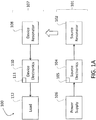
- FIG. 1A is a schematic diagram of an embodiment of a wireless power transfer system.
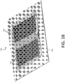
- FIG. 1B is a schematic diagram of a resonator for wireless power transfer.
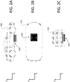
- FIGS. 2A-2C are schematic diagrams of a wireless power transfer system integrated into a vehicle. Winding overlaps the at least some of the other windings can be equally spaced along a circumference of the one winding.
- the at least two windings can include n windings, each one winding of the n windings can spatially overlap each of the other n-1 windings along the length of the one winding, and each one winding of the n windings can include n-1 points of overlap with the other windings, each one of the points corresponding to overlap of the one winding with a different one of the other windings.
- the quantity n can be greater than two (e.g., greater than three).
- the at least two windings can include n windings, and at least one winding of the n windings can include more than n -1 points of overlap with the other windings so that the at least one winding spatially overlaps at least some of the other n -1 windings more than once.
- the at least two windings can include n windings, and at least one winding of the n windings can include fewer than n -1 points of overlap with the other windings so that the at least one winding does not spatially overlap all of the other n -1 windings.
- Embodiments of the systems, methods, and coils can also include any of the other features disclosed herein, including features disclosed in connection with different embodiments, in any combination as appropriate.
- the wireless power transfer systems disclosed herein use one or more source resonators to generate oscillating magnetic fields.
- the oscillating magnetic fields are captured by, and induce electrical currents and voltages in, one or more receiving resonators.
- the receiving resonators can be coupled to loads, and the electrical currents and voltages can be used to drive the loads to do useful work.
- the receiving resonators can also act as relay resonators, further transmitting power wirelessly by generating additional oscillating magnetic fields.
- Wireless power transfer systems can be integrated into a variety of devices and used for a wide range of power-demanding applications.
- such systems can be integrated into electric vehicles and used to power and/or charge the vehicles.
- Such systems can also be used to power electronic devices, including fixed and portable devices, and can be integrated into a diverse range of structures including furniture (e.g., desks, tables) and structural features (e.g., floors, walls, columns, streets).
- the systems can provide power in quantities that range from very small amounts to significant quantities for high-power applications.
- the systems disclosed herein may provide power greater than 1 kW, 3 kW, 5 kW, 10 kW, 20 kW, 50 kW, or more from one or more source resonators to one or more receiving resonators connected to electrical devices.
- FIG. 1A shows a schematic diagram of an embodiment of a wireless power transfer system 100 that includes a wireless power source 101 and device 107.
- Wireless power source 101 includes a source resonator 102 coupled to source electronics 104, which are connected to a power supply 106.
- Source electronics 104 can include a variety of components including an AC/DC converter, an amplifier, and an impedance matching network.
- Power supply 106 can include one or more of AC mains, solar panels, and one or more batteries. Not all of the components of power source 101 need to be present for operation, and in some embodiments, certain components shown in FIG. 1A can be integrated (source electronics 104 and power supply 106 can be integrated into a single component, for example).
- Device 107 includes a device resonator 108 coupled to device electronics 110 to provide power to a load 112.
- Device electronics 110 can include a variety of components, such as a rectifier and/or an impedance matching network.
- Load 112 generally corresponds to any of a variety of power-dissipating electrical components, such as a battery and/or an electromechanical device. Not all of the components of device 107 need to be present for operation, and in some embodiments, certain components shown in FIG. 1A can be integrated (device electronics 110 and load 112 can be integrated into a single component, for example).
- Source electronics 104 and device electronics 110 can each include one or more electronic processors (processors 105 and 111, respectively).
- Electronic processors 105 and 111 can perform a variety of monitoring, computation, and control functions. For example, as will be described in more detail subsequently, processors 105 and/or 111 can measure electrical parameters of various system components (by directing suitable control signals to various sensors), calculate various performance-related metrics and attributes based on measurement signals received from the sensors, and transmit control signals to various system components based on the calculated metrics and attributes.
- processors 105 and 111 can be configured to perform any of the monitoring, computational, and control functions disclosed herein.
- source electronics 104 and/or device electronics 111 can include dedicated electrical circuits (e.g., application-specific integrated circuits) and logic units (e.g., programmable logic arrays) that can be configured to perform any one or more of these functions.
- dedicated electrical circuits e.g., application-specific integrated circuits
- logic units e.g., programmable logic arrays
- Processors 105 and/or 111 can be coupled to one or more components of system 100 in various configurations. In some embodiments, processors 105 and/or 111 are coupled to system components via a direct electrical connection. In certain embodiments, processors 105 and/or 111 are coupled to system components via wireless communication (e.g., radio-frequency, Bluetooth communication). The coupling between the processors and the system components can be different for different system components. For example, processor 105 can be directly connected to power supply 106 and source resonator 102, and coupled wirelessly to device resonator 108 and/or device electronics 110.
- wireless communication e.g., radio-frequency, Bluetooth communication
- processor 105 can direct power supply 106 to provide power to source resonator 102.
- processor 105 can increase the power output of power supply 106, thereby increasing the power delivered to source resonator 102.
- the power output can be delivered at an operating frequency corresponding to a frequency of the oscillating magnetic field that is generated by source resonator 102.
- processor 105 can tune a resonant frequency of source resonator 102 and/or a resonant frequency of device resonator 108.
- processor 105 can tune the resonant frequencies of source resonator 102 and/or device resonator 108 to be substantially the same (e.g., within 0.5%, within 1%, within 2%) to increase the efficiency of power transfer.
- processors 105 and/or 111 can tune the resonant frequencies by adjusting capacitance values of components in source resonator 102 and/or source electronics 104. Resonant frequencies can also be tuned by adjusting capacitance values of components in device resonator 108 and/or device electronics 110. For example, to tune the resonance frequency of source resonator 102, processor 105 can adjust a capacitance of a capacitor connected to a coil in source resonator 102. The adjustment can be based on a measurement of the resonance frequency by processor 105 and/or based on a communication signal transmitted from source resonator 102 and/or device resonator 108 to processor 105 (e.g., transmitted wirelessly).
- processor 105 can tune the resonant frequency of source resonator 102 to be substantially the same (e.g., within 0.5%, within 1%, within 2%) as the operating frequency of power supply 106. In some embodiments, processor 105 can tune the resonant frequency of source resonator 102 to be different from the operating frequency by 7% to 13% (e.g., 10% to 15%, 13% to 19%). Similar considerations apply to the tuning of the resonance frequency of device resonator 108 (e.g., by processor 111 and/or processor 105).
- processors 105 and/or 111 can control an impedance matching network in system 100 to adjust impedance matching conditions in the system, and thereby control the efficiency of power transfer.
- processor 105 can tune the capacitance of capacitors or networks of capacitors in an impedance matching network connected between power supply 106 and source resonator 102 (e.g., as part of source electronics 104).
- processor 105 can tune the inductance of inductors or networks of inductors in an impedance matching network.
- the optimum impedance conditions can be calculated by processor 105 and/or can be received from an external device.
- processor 111 can control impedance matching conditions by tuning the capacitance and/or inductance of capacitors and/or inductors, respectively, in an impedance matching network connected between device resonator 108 and load 112 (e.g., as part of device electronics 110). Additional aspects of frequency tuning and impedance matching networks are disclosed, for example, in U.S. Patent Application Publication No. 2015/0051750 .
- wireless energy transfer from one coil (e.g., a resonator coil) to another coil (e.g., another resonator coil) refers to transferring energy to do useful work (e.g., electrical work, mechanical work, etc.) such as powering electronic devices, vehicles, lighting a light bulb or charging batteries.
- useful work e.g., electrical work, mechanical work, etc.
- wireless power transfer from one coil (e.g., resonator coil) to another resonator (e.g., another resonator coil) refers to transferring power to do useful work (e.g., electrical work, mechanical work, etc.) such as powering electronic devices, vehicles, lighting a light bulb or charging batteries.
- wireless energy transfer and wireless power transfer refer to the transfer (or equivalently, the transmission) of energy to provide operating power that would otherwise be provided through a wired connection to a power source, such as a connection to a main voltage source.
- a power source such as a connection to a main voltage source.
- FIG. 1B is a schematic diagram showing a portion of a resonator 150 used for wireless power transfer.
- Resonator 150 includes a coil 152, a magnetic member 154, and a shield 156.
- Coil 152 includes one or more loops and can be connected to one or more capacitors and/or inductors, as well as other electrical components (not shown).
- Coil 152 is formed of one or more conductive materials, such as copper, silver, gold, and Litz wire. As an example, Litz wire can be used for operation at frequencies of lower than 1 MHz (e.g., 85 kHz).
- the coil 210 can be formed of a solid core wire, or one or more conducting layers (e.g., copper layers) formed on a printed circuit board (PCB). For example, solid core wire or conducting layers can be used at operation frequencies of 1 MHz or higher.
- PCB printed circuit board
- Magnetic member 154 is positioned between coil 152 and shield 154. That is, in FIG. 1A , coil 152 is positioned on one side of magnetic member 154 and shield 156 is positioned on the opposite side of magnetic member 156.
- magnetic member 154 guides magnetic flux induced by current flowing in the loops of coil 152. The presence of magnetic member 154 can lead to an increase in the magnetic flux density generated by coil 152 in a region adjacent to coil 152 (i.e., in a plane above or below the plane of coil 152) when oscillating electrical currents circulate in coil 152, relative to the flux density in the absence of magnetic member 154.
- magnetic member 154 can include one or more magnetic elements formed from magnetic materials such as manganese-zinc (MnZn) and/or nickel-zinc (NiZn) ferrites.
- MnZn manganese-zinc
- NiZn nickel-zinc
- the gaps between elements can be filled with a dielectric material such as an adhesive.
- magnetic members While magnetic materials are generally available in small sizes, some applications for wireless power transfer utilize magnetic members with a large areal size. For example, a car battery charging application may use magnetic members of large areal size (e.g., 30 cm ⁇ 30 cm) to transfer high power of 1 kW or more (e.g., 2 kW or more, 3 kW or more, 5 kW or more, 6 kW or more). Magnetic members featuring a single monolithic piece of material can be utilized when such a piece of material is available. However, it can be difficult and/or expensive to manufacture a monolithic piece of magnetic material such as MnZn or NiZn ferrites with a large areal size (e.g., 30 cm ⁇ 30 cm) for high power transfer. Moreover, MnZn and NiZn ferrites can be brittle, and accordingly, large-area pieces of these materials can be highly susceptible to breakage.
- MnZn and NiZn ferrites can be brittle, and accordingly, large-area pieces of these materials can be highly susceptible to break
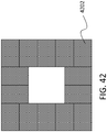
- ferrite materials can be manufactured in pieces of small areal size (e.g., 5 cm ⁇ 5cm), and several such pieces can be joined together to form a larger combined magnetic member.
- the smaller magnetic elements can behave functionally in a collective manner very similar to a larger magnetic member when they are joined.
- the multiple magnetic elements can be contained in a holder made from thermally conducting and electrically insulating materials (e.g., plastic, Teflon®, aluminum oxide, aluminum nitride, etc.)
- Shield 156 which generally corresponds to a sheet of electrically conductive material, is typically positioned in proximity to coil 152.
- Shield 156 can be formed from one or more conductive materials, which can be the same as, or different from, the conductive materials used to form coil 152.
- shield 156 can be formed from a sheet of a material such as copper, silver, gold, iron, steel, nickel and/or aluminum.
- Shield 156 acts to shield coil 152 from loss-inducing objects (e.g., metallic objects).
- shield 156 can increase coupling of resonator 150 to another resonator by guiding magnetic field lines in the vicinity of the resonator. For example, energy loss from aberrant coupling to loss-inducing objects can be reduced by using shield 156 to guide magnetic field lines away from the loss-inducing objects.
- FIGS. 2A-2C are schematic diagrams showing a wireless power transfer system 204 integrated into a vehicle 202.
- FIG. 2A shows a side view of vehicle 202 in the X-Z coordinate plane
- FIG. 2B shows a top view of vehicle 202 in the X-Y coordinate plane
- FIG. 2C shows a front view of vehicle 202 in the Y-Z coordinate plane.
- the X-axis corresponds to the "front-to-back" direction of the vehicle
- the Y-axis corresponds to the "side-to-side” direction of the vehicle
- the Z-axis corresponds to the "top-to-bottom" direction of the vehicle.
- source and device resonators can be relatively large to accommodate significant power transfer between the resonators.
- the source resonator can have a maximum dimension in the X-Y plane of 30 cm or more (e.g., 40 cm or more, 50 cm or more, 60 cm or more, 70 cm or more, 80 cm or more, 90 cm or more, 100 cm or more).
- the device resonator can have a maximum dimension in the X-Y plane of 20 cm or more (e.g., 30 cm or more, 40 cm or more, 50 cm or more, 60 cm or more, 70 cm or more, 80 cm or more, 90 cm or more, 100 cm or more).
- a maximum dimension of the source resonator can be smaller than a maximum dimension of the device resonator by 10 cm or more (e.g., by 15 cm or more, by 20 cm or more, by 30 cm or more).
- the source and device resonator can each have a variety of different cross-sectional shapes, including square, rectangular, circular, elliptical, and more generally, regular polygonal.
- the resonators can have different shapes.
- the source resonator can have a square cross-sectional shape
- the device resonator can have a rectangular cross-sectional shape.
- the resonant frequency f of a source or receiver resonator is typically determined by the resonator's capacitance and inductance values.
- any one of a source, receiver, and/or repeater resonator can have a Q-factor that is a high Q-factor where Q>100 (e.g., Q>100, Q>200, Q>300, Q>500, Q>1000).
- wireless power transfer systems can include a power source having one or more source resonators, and at least one of the source resonators can have a Q-factor of Q 1 >100 (e.g., Q 1 >100, Q 1 >200, Q 1 >300, Q 1 >500, Q 1 >1000).
- the wireless power transfer system can include a power receiver having one or more receiver resonators, and at least one of the receiver resonators can have a Q-factor of Q 2 >100 (e.g., Q 2 >100, Q 2 >200, Q 2 >300, Q 2 >500, Q 2 >1000).
- the system can include at least one repeater resonator having a Q-factor of Q 3 >100 (e.g., Q 3 >100, Q 3 >200, Q 3 >300, Q 3 >500, Q 3 >1000).
- Utilizing high Q-factor resonators can lead to large energy coupling between some or all of the resonators in a wireless power transfer system.
- the high Q factors can lead to strong coupling between resonators such that the "coupling time" between the resonators is shorter than the "loss time” of the resonators.
- energy can be transferred efficiently between resonators at a faster rate than the energy loss rate due to losses (e.g., heating loss, radiative loss) of the resonators.
- a resonator coil can be offset from a conductive shield (e.g., an aluminum shield) to decrease losses and increase coupling to another resonator.
- FIGS. 3A-3B are schematic diagrams showing a source resonator coil 302 in proximity to a magnetic material 304, with a gap between magnetic material 304 and a conductive shield 306. In FIG. 3A , there is no gap between magnetic material 304 and shield 306. In FIG. 3B , there is a 40 mm gap 308 between magnetic material 304 and shield 306 (an aluminum shield).
- a coupling rate k is measured to be approximately 0.077 for source resonator 302 shown in FIG. 3A , and approximately 0.083 for source resonator 302 shown in FIG. 3B .
- the thickness of magnetic material 304 in proximity to (or even attached to) a resonator can be varied to adjust the coupling k to another resonator.
- the source resonator coil and magnetic material are spaced from the aluminum shield by a gap of 40 mm, as in FIG. 3B discussed previously.
- Measurements of k are taken for a source resonator coil 402 having different thicknesses of magnetic material (e.g., "ferrite"), and under conditions when a vehicle chassis is present and not present.
- Table 1 Presence of Vehicle Chassis Ferrite thickness Coupling k Chassis present 5 mm 0.060 Chassis not present 5 mm 0.075 Chassis not present 12 mm 0.083
- a device configured to receive power wirelessly can be house both a device resonator and device electronics an integrated manner.
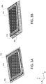
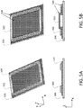
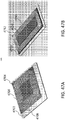
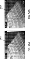
- FIG. 5A is a schematic diagram showing an embodiment of a device configured to wirelessly receive power in which a device resonator coil 502, a magnetic material 504, and a conductive (e.g., aluminum) shield 506 are stacked onto one another.
- FIG. 5B shows a schematic diagram of another embodiment of a device configured to wirelessly receive power.
- the device of FIG. 5B has a "top-hat" configuration, in which a center portion of magnetic material 508 is stepped in the Z-direction to form an empty region between magnetic material 508 and shield 506.
- Device electronics 510 are positioned within the empty region and coil 502 is wound around the stepped edges of magnetic material 508. By enclosing device electronics 510 within the device resonator as shown in FIG. 5B , the compactness of the device can be significantly increased.
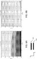
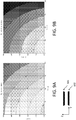
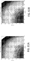
- FIGS. 6A and 6B are plots that show measurements of the coupling k between a source resonator and a receiver resonator 604 as a function of relative displacement between the centers of the resonators in both the X- and Z-directions.
- the receiver resonator is similar to the resonator shown in FIG. 5A and the source resonator is similar to the resonator shown in FIG. 3B .
- the plot in FIG. 6A shows measurements of the coupling k in the absence of a vehicle chassis, while the plot in FIG. 6B shows measurements in the presence of an aluminum vehicle chassis. It is evident from FIGS. 6A and 6B that the vehicle chassis reduces the value of the coupling k by approximately 20%.
- FIGS. 7A and 7B are plots showing figure-of-merit (Uo) measurements as a function of relative displacement between the centers of a source resonator 602 and receiver resonator 604, in the X- and Z-directions.
- the receiver resonator is similar to the resonator shown in FIG. 5A and the source resonator is similar to the resonator shown in FIG. 3B .
- the plot in FIG. 7A shows measurements of Uo in the absence of a vehicle chassis, while the plot in FIG. 7B shows measurements in the presence of an aluminum vehicle chassis.
- the quality factor of the source resonator is approximately 1000 while the quality factor of the receiver resonator is approximately 380.
- the quality factor of the source resonator is approximately 1000, while the quality factor of the receiver resonator is approximately 460.
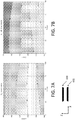
- FIGS. 8A and 8B are plots showing measurements of the coupling k as a function of relative displacement between the centers of a source resonator 602 and a receiver resonator 604 in the Y- and Z-directions.
- the receiver resonator is similar to the resonator shown in FIG. 5A and the source resonator is similar to the resonator shown in FIG. 3B .
- the plot in FIG. 8A shows measurements of k in the absence of a vehicle chassis, while the plot in FIG. 8B shows measurements in the presence of an aluminum vehicle chassis. It is evident that the vehicle chassis reduces the coupling k by approximately 20%.
- FIGS. 9A and 9B are plots showing figure-of-merit (Uo) measurements as a function of relative displacement between the centers of a source resonator 602 and a receiver resonator 604 in the Y- and Z-directions.
- the receiver resonator is similar to the resonator shown in FIG. 5A and the source resonator is similar to the resonator shown in FIG. 3B .
- the plot in FIG. 9A shows measurements of Uo in the absence of a vehicle chassis, while the plot in FIG. 9B shows measurements in the presence of an aluminum vehicle chassis.
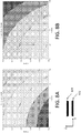
- FIGS. 10A and 10B are plots showing measurements of the coupling k as a function of relative displacement between centers of a source resonator 602 and receiver resonator 604 in the X- and Z-directions.
- the receiver resonator is similar to the resonator shown in FIG. 5B (i.e., a "top hat" configuration) and the source resonator is similar to the resonator shown in FIG. 3B .
- the plot in FIG. 10A shows measurements of k in the absence of a vehicle chassis, while the plot in FIG. 10B shows measurements in the presence of an aluminum vehicle chassis.
- the measured values of k in FIGS. 10A and 10B do not differ substantially from the measured values shown in the plots of FIGS. 6A and 6B , respectively.
- FIGS. 11A and 11B are plots showing figure-of-merit (Uo) measurements as a function of relative displacement between centers of a source resonator 602 and receiver resonator 604 in the X- and Z-directions.
- the receiver resonator is similar to the resonator shown in FIG. 5B (i.e., a "top hat" configuration) and the source resonator is similar to the resonator shown in FIG. 3B .
- the plot in FIG. 11A shows measurements of Uo in the absence of a vehicle chassis, while the plot in FIG. 11B shows measurements in the presence of an aluminum vehicle chassis.
- the quality factor Q for the source resonator is 1000 while the quality factor Q for the receiver resonator is 450.
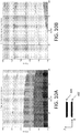
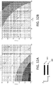
- FIGS. 12A and 12B are plots showing measurements of the coupling k as a function of relative displacement between centers of a source resonator 602 and receiver resonator 604 in the Y- and Z-directions.
- the receiver resonator is similar to the resonator shown in FIG. 5B (i.e., a "top hat" configuration) and the source resonator is similar to the resonator shown in FIG. 3B .
- the plot in FIG. 12A shows measurements of k in the absence of a vehicle chassis, while the plot in FIG. 12B shows measurements in the presence of an aluminum vehicle chassis.
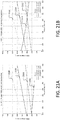
- FIGS. 13A and 13B are plots showing figure-of-merit (Uo) measurements as a function of relative displacement between centers of a source resonator 602 and receiver resonator 604 in the Y- and Z-directions.
- the receiver resonator is similar to the resonator shown in FIG. 5B (i.e., a "top hat" configuration) and the source resonator is similar to the resonator shown in FIG. 3B .
- the plot in FIG. 13A shows measurements of Uo in the absence of a vehicle chassis, while the plot in FIG. 13B shows measurements in the presence of an aluminum vehicle chassis.
- the quality factor Q for the source resonator is 1000 while the quality factor Q for the receiver resonator is 450.
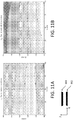
- FIGS. 14A and 14B are plots showing measurements of the coupling k as a function of relative displacement between centers of a source resonator 602 and receiver resonator 604 in the X- and Z-directions.
- the receiver resonator is similar to the resonator shown in FIG. 5B (i.e., a "top hat" configuration) and the source resonator is similar to the resonator shown in FIG. 3B .
- the plot in FIG. 14A shows measurements of k in the presence of an aluminum vehicle chassis, while the plot in FIG. 14B shows measurements of k in the presence of a steel (e.g., ST1008 steel) vehicle chassis. It is evident from FIGS. 14A and 14B that replacing the aluminum chassis with a steel chassis does not have a significant effect on the coupling k.
- a steel e.g., ST1008 steel
- FIGS. 15A and 15B are plots showing measurements of the quality factor Qo as a function of relative displacement between centers of a source resonator 602 and a receiver resonator 604 in the X- and Z-directions.
- the receiver resonator is similar to the resonator shown in FIG. 5B (i.e., a "top hat” configuration) and the source resonator is similar to the resonator shown in FIG. 3B .
- the plot in FIG. 15A shows source resonator Q 0,src measurements in the presence of a steel vehicle chassis.
- the plot in FIG. 15B shows receiver ("device") resonator Q 0,dev measurements in the presence of a steel vehicle chassis. Both source resonator Q 0,src and receiver resonator Q 0,dev are significantly reduced compared to measured values in the presence of an aluminum vehicle chassis or no vehicle chassis.
- FIGS. 16A and 16B are plots showing figure-of-merit (Uo) measurements as a function of relative displacement between centers of a source resonator 602 and a receiver resonator 604 in the X- and Z-directions.
- the receiver resonator is similar to the resonator shown in FIG. 5B (i.e., a "top hat” configuration) and the source resonator is similar to the resonator shown in FIG. 3B .
- the plot in FIG. 16A shows Uo measurements in the presence of an aluminum vehicle chassis, while the plot in FIG. 16B shows Uo measurements in the presence of a steel (“ST1008”) vehicle chassis.
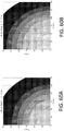
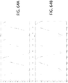
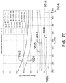
- FIGS. 60A and 60B are plots showing measured values of the coupling k between source and device resonators that are similar to those shown in FIGS. 44 and 46 , respectively, as a function of relative displacements between the centers of the resonators in the X- and Y-directions.
- the source and device resonators are spaced from one another by 15 cm in the Z-direction.
- the plot in FIG. 60A shows measurements of k in the presence of a vehicle chassis, while the plot in FIG. 60B shows measurements of k with no vehicle chassis present.
- FIGS. 61A and 61B are plots showing measured values of the coupling k between the same source and device resonators as in FIGS. 60A and 60B as a function of relative displacements between the centers of the resonators in the X- and Y-directions.
- the source and device resonators are spaced from one another by 10 cm in the Z-direction.
- the plot in FIG. 61A shows measurements of k in the presence of a vehicle chassis, while the plot in FIG. 61B shows measurements of k with no vehicle chassis present. The presence of the vehicle chassis reduces the coupling k by between 1% and 8%.
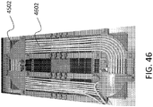
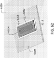
- FIG. 62 shows a schematic diagram of a receiver resonator that includes a resonator coil 6202, a magnetic member 6204, a first conductive shield 6206, and a second conductive shield 6208.
- the receiver resonator is positioned in proximity to a vehicle chassis 6210 formed of steel (e.g., ST1008).
- Second conductive shield 6208 is formed of aluminum, and is square in shape with a side length 6212.
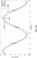
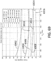
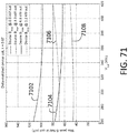
- FIG. 63 is a plot showing measured Q-factor values for the source resonator (curve 6302) and receiver resonator (curve 6304) as a function of the side length 6212 of second shield 6208.
- the source and receiver resonators are displaced from one another by 10 cm in both the X- and Y-directions, and by 10 cm in the Z-direction, a relative offset at which the effect of the vehicle chassis on the source resonator is greatest.
- the side length 6212 of second shield 6208 is preferably 80 cm or larger to mitigate the lossy effect of the steel vehicle chassis 6210.
- impedance matching networks and configurations can be used in the wireless power transfer systems disclosed herein to ensure that power is transferred efficiently between source and receiver resonators.
- Various features and aspects of impedance matching networks are discussed, for example, in U.S. Patent Application Publication No. 2012/0242225 , the entire contents of which are incorporated herein by reference.
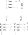
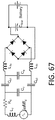
- FIG. 17A is a schematic diagram showing an example of an impedance matching network for a source resonator that implements a "balanced LCL" matching scheme.
- FIG. 17B is a schematic diagram showing an example of an impedance matching network for a receiver resonator that implements a "balanced series” matching scheme.
- These impedance matching networks can be used, for example, at power levels greater than 3 kW, and even greater than 7 kW.
- a wireless power transfer system can include a source resonator with a quality factor Q 0,src of approximately 1000 and a receiver resonator with a quality factor Q 0,dev of approximately 450.
- the maximum coupling k value for this system can be approximately 0.12.
- the minimum coupling k value for a source and receiver resonator of a wireless power transfer system (referring to FIGS. 6A-6B , 7A-7B , 10A-10B , 11A-11B , and 14A-14B ) can be approximately 0.08.
- the minimum coupling k value for a source and receiver resonator of a wireless power transfer system in the Y-Z plane (referring to FIGS. 8A-8B , 9A-9B , 12A-12B , and 13A-13B ) can be approximately 0.06.
- the impedance matching point of the receiver resonator may be chosen such that the maximum power dissipated in the device, including the impedance matching network and diodes, is less than 300 W (e.g., less than 275 W, less than 250 W, less than 225 W, less than 200 W).
- Impedance matching networks can generally include a variety of different electronic components.
- the capacitor voltage rating can determine the target inductances of the resonator coils.
- Other types of less expensive capacitors can also be used in certain embodiments, including film capacitors for example.
- FIGS. 18A and 18B are plots of measured device-side load impedance as a function of output voltage for a device with a receiver resonator as shown in FIG. 5B , in the presence of an aluminum vehicle chassis.
- FIG. 18A shows measured device-side load impedance for a power level of 3.7 kW
- FIG. 18B shows measured device-side load impedance for a power level of 7.4 kW.
- FIGS. 19A and 19B are plots of amplifier-to-battery efficiency as a function of output voltage for a device with a receiver resonator as shown in FIG. 5B , in the presence of an aluminum vehicle chassis.
- FIG. 19A shows amplifier-to-battery efficiency for coupling k values of 0.12 (curve 1902), 0.08 (curve 1904), and 0.06 (curve 1906) for a power level of 3.7 kW.
- FIG. 19B shows amplifier-to-battery efficiency for coupling k values of 0.12 (curve 1908), 0.08 (curve 1910), and 0.06 (curve 1912) for a power level of 7.4 kW.
- efficiency values at the lower of the coupling k values can be improved by matching to a lower figure-of-merit U d .
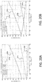
- FIGS. 20A and 20B are plots of power dissipated in a source (with a resonator corresponding to the source resonator shown in FIG. 3B ) and a device (with a receiver resonator corresponding to the receiver resonator shown in FIG. 5B ) as a function of output voltage, in the presence of an aluminum vehicle chassis.
- FIG. 20A shows power dissipated in the source for coupling k values of 0.12 (curve 2002), 0.08 (curve 2004), 0.06 (curve 2006), and in the device (curve 2008) at a power level of 3.7 kW.
- FIG. 20B shows power dissipated in the source for coupling k values of 0.12 (curve 2010), 0.08 (curve 2012), 0.06 (curve 2014) and in the device (curve 2016) at a power level of 7.4 kW.
- FIGS. 21A and 21B are plots of the voltage (V rms ) measured across one or more capacitors in an impedance matching network for a system that includes a source (with a resonator corresponding to the source resonator shown in FIG. 3B ) and a device (with a receiver resonator corresponding to the receiver resonator shown in FIG. 5B ) as a function of output voltage, in the presence of an aluminum vehicle chassis. Voltages in FIGS. 21A and 21B are measured across capacitors C 1a and C 1b shown in FIGS. 17A and 17B .
- FIG. 21A and 21B are plots of the voltage (V rms ) measured across one or more capacitors in an impedance matching network for a system that includes a source (with a resonator corresponding to the source resonator shown in FIG. 3B ) and a device (with a receiver resonator corresponding to the receiver resonator shown in FIG. 5B )
- FIG. 21A shows the RMS voltage across capacitor C 1 for a source with coupling k values of 0.12 (curve 2104), 0.08 (curve 2106), and 0.06 (curve 2108), and for a device (curve 2102) at a power level of 3.7 kW.
- FIG. 21B shows the RMS voltage across capacitor C 1 for a source with coupling k values of 0.12 (curve 2112), 0.08 (curve 2114), and 0.06 (curve 2116), and for a device (curve 2110) at a power level of 7.4 kW.
- FIGS. 22A and 22B are plots of the magnetic field (mT) measured in the magnetic member attached to the resonators in a wireless power transfer system (i.e., attached to a source resonator such as the resonator shown in FIG. 3B and attached to a receiver resonator as shown in FIG. 5B ), as a function of output voltage, in the presence of an aluminum vehicle chassis.
- the magnetic member is formed from 5 mm ferrite pieces.
- FIG. 22A shows the magnetic field in the magnetic member of a source resonator for coupling k values of 0.12 (curve 2204), 0.08 (curve 2206), and 0.06 (curve 2208), and in a receiver resonator (curve 2202) at a power level of 3.7 kW.
- FIG. 22BB shows the magnetic field in the magnetic member of a source resonator for coupling k values of 0.12 (curve 2212), 0.08 (curve 2214), and 0.06 (curve 2216), and in a receiver resonator (curve 2210) at a power level of 7.4 kW.
- FIG. 23 shows a schematic circuit diagram of an embodiment of device electronics 110.
- the device electronics include a device resonator coil 2302 with series tuning, represented by series capacitors 2304 and 2306.
- the device electronics can include a half-wave or full-wave rectification stage 2310, one or more filters 2312, and/or a DC-to-DC converter 2314.
- the DC-DC converter can be used to tune the load impedance that the device sees to achieve an improved and/or optimal impedance matching value.
- Load 112 can correspond to a variety of electronic devices such as, for example, a battery 2316.
- DC-DC converter 2314 can be a boost converter to minimize the voltage across capacitors C 1a and C 1b .
- DC-DC converter 2314 can be a buck converter to reduce losses in the rectification diodes.
- FIGS. 24A and 24B are plots showing the DC-DC boost conversion ratio for a device with a receiver resonator (such as the receiver resonator shown in FIG. 5B ) as a function of output voltage, in the presence of an aluminum vehicle chassis.
- FIG. 24A shows the DC-DC conversion ratio for a device with a receiver resonator having coupling k values of 0.12 (curve 2402), 0.08 (curve 2404), and 0.06 (curve 2406) at a power level of 3.7 kW.
- FIG. 24A shows the DC-DC conversion ratio for a device with a receiver resonator having coupling k values of 0.12 (curve 2402), 0.08 (curve 2404), and 0.06 (curve 2406) at a power level of 3.7 kW.
- FIG. 24B shows the DC-DC conversion ratio for a device with a receiver resonator having coupling k values of 0.12 (curve 2402), 0.08 (curve 2404), and 0.06 (curve 2406) at a power level of 7.4 kW.
- a DC-DC boost conversion ratio of approximately 4:1 can be optimal for operation at both 3.7 kW and 7.4 kW for various positional offsets between the source and device resonators as well as output voltages.
- FIGS. 25A and 25B are plots showing the amplifier-to-converter efficiency for a device with a receiver resonator (such as the receiver resonator shown in FIG. 5B ) as a function of output voltage, in the presence of an aluminum vehicle chassis.
- FIG. 25A shows the efficiency for a device with a receiver resonator having coupling k values of 0.12 (curve 2502), 0.08 (curve 2504), and 0.06 (curve 2506) at a power level of 3.7 kW.
- FIG. 25B shows the efficiency for a device with a receiver resonator having coupling k values of 0.12 (curve 2502), 0.08 (curve 2504), and 0.06 (curve 2506) at a power level of 7.4 kW.
- FIGS. 26A and 26B are plots showing power dissipated in a source that includes a source resonator (such as the source resonator shown in FIG. 3B ) and in a device that includes a receiver resonator (such as the receiver resonator shown in FIG. 5B ) as a function of output voltage in the presence of an aluminum vehicle chassis.
- FIG. 26A shows the power dissipated in a source for coupling k values of 0.12 (curve 2602), 0.08 (curve 2604), and 0.06 (curve 2606), and in a device for coupling k values of 0.12 (curve 2608), 0.08 (curve 2610), and 0.06 (curve 2612) at a power level of 3.7 kW.
- FIG. 26B shows the power dissipated in a source for coupling k values of 0.12 (curve 2614), 0.08 (curve 2616), and 0.06 (curve 2618), and in a device for coupling k values of 0.12 (curve 2620), 0.08 (curve 2622), and 0.06 (curve 2624) at a power level of 7.4 kW.
- FIGS. 27A and 27B are plots showing measured voltages across one or more matching network capacitors in a source that includes a source resonator (such as the source resonator shown in FIG. 3B ) and in a device that includes a receiver resonator (such as the receiver resonator shown in FIG. 5B ) as a function of output voltage in the presence of an aluminum vehicle chassis.
- a source resonator such as the source resonator shown in FIG. 3B
- a receiver resonator such as the receiver resonator shown in FIG. 5B
- FIG. 27A shows the voltage across one or more matching network capacitors in a source for coupling k values of 0.12 (curve 2702), 0.08 (curve 2704), and 0.06 (curve 2706), and across one or more matching network capacitors in a device for coupling k values of 0.12 (curve 2708), 0.08 (curve 2710), and 0.06 (curve 2712) at a power level of 3.7 kW.
- FIG. 27A shows the voltage across one or more matching network capacitors in a source for coupling k values of 0.12 (curve 2702), 0.08 (curve 2704), and 0.06 (curve 2706), and across one or more matching network capacitors in a device for coupling k values of 0.12 (curve 2708), 0.08 (curve 2710), and 0.06 (curve 2712) at a power level of 3.7 kW.
- FIG. 27B shows the voltage across one or more matching network capacitors in a source for coupling k values of 0.12 (curve 2714), 0.08 (curve 2716), and 0.06 (curve 2718), and across one or more matching network capacitors in a device for coupling k values of 0.12 (curve 2720), 0.08 (curve 2722), and 0.06 (curve 2724) at a power level of 7.4 kW.
- FIGS. 28A and 28B are plots of the magnetic field (mT) measured in a magnetic member attached to the source and receiver resonators in a wireless power transfer system, where the source resonator is similar to the resonator shown in FIG. 3B and the receiver resonator is similar to the resonator shown in FIG. 5B , as a function of output voltage, in the presence of an aluminum vehicle chassis.
- FIG. 1 the magnetic field
- FIG. 28A shows the magnetic field measured in the magnetic member of the source for coupling k values of 0.12 (curve 2802), 0.08 (curve 2804), and 0.06 (curve 2806), and in the magnetic member of the device for coupling k values of 0.12 (curve 2808), 0.08 (curve 2810), and 0.06 (curve 2812) at a power level of 3.7 kW.
- FIG. 28A shows the magnetic field measured in the magnetic member of the source for coupling k values of 0.12 (curve 2802), 0.08 (curve 2804), and 0.06 (curve 2806), and in the magnetic member of the device for coupling k values of 0.12 (curve 2808), 0.08 (curve 2810), and 0.06 (curve 2812) at a power level of 3.7 kW.
- FIG. 28B shows the magnetic field measured in the magnetic member of the source for coupling k values of 0.12 (curve 2814), 0.08 (curve 2816), and 0.06 (curve 2818), and in the magnetic member of the device for coupling k values of 0.12 (curve 2820), 0.08 (curve 2822), and 0.06 (curve 2824) at a power level of 7.4 kW.
- wireless power transfer systems can include a switchable, multi-tapped transformer to variably tune the impedance of source and/or receiver resonators.
- wireless power transfer systems can include a DC-DC converter to modulate the output impedance.
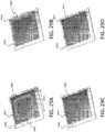
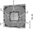
- FIGS. 29A-29D are schematic diagrams showing exemplary embodiments of resonator coils for wireless power transfer systems.
- the resonator winding length 2914 and span 2916 varies.
- the size of magnetic member 2904 is 50 cm x 50 cm x 5 mm
- the size of shield 2902 is 60 cm x 60 cm.
- Magnetic member 2904 is formed from ferrite
- shield 2902 is formed from aluminum.
- FIG. 29A shows a resonator coil 2906 with a minimum length of 400 mm and minimum span of 50 mm.
- FIG. 29B shows a resonator coil 2908 with a maximum length of 500 mm and minimum span of 50 mm.
- FIG. 29C shows a resonator coil 2910 with a minimum length of 400 mm and maximum span of 175 mm.
- FIG. 29D shows a resonator coil 2912 with a maximum length of 500 mm and maximum span of 175 mm.
- the resonators shown in FIGS. 29A-29D can be used as source resonators (such as the source resonator shown in FIG. 3B ).
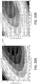
- the receiver resonator dimensions are 25 mm by 50 mm.
- the dark region 3002 with greater coupling k indicates that a winding length of 500 mm and winding span of 130 mm result in higher coupling for certain source resonator coil dimensions.
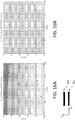
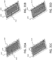
- FIGS. 31A-31D are schematic diagrams showing exemplary embodiments of resonator coils for wireless power transfer systems.
- the winding gap-to-edge distance 3114 and span 3116 vary.
- the size of magnetic member 3104 is 20 cm x 45 cm x 5 mm, and the size of shield 3102 is 25 cm x 50 cm.
- Magnetic member 3104 is formed from ferrite, and shield 3102 is formed from aluminum.
- FIG. 31A shows a resonator coil 3106 with a minimum gap-to-edge distance of 0 mm and a minimum span of 25 mm.
- FIG. 31B shows a resonator coil 3108 with a maximum gap-to-edge distance of 20 mm and a minimum span of 25 mm.
- FIG. 31C shows a resonator coil 3110 with a minimum gap-to-edge distance of 0 mm and a maximum span of 50 mm.
- FIG. 31D shows a resonator coil 3112 with a maximum gap-to-edge distance of 20 mm and a maximum span of 50 mm.
- the resonators shown in FIGS. 31A-31D can be used as receiver resonators in devices, for example.
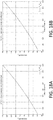
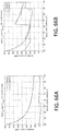
- FIG. 32A is a plot of coupling k as a function of resonator coil winding gap-to-edge distance and span for the resonators of FIGS. 31A-31D . Highest coupling is achieved for resonator coils with a winding gap-to-edge distance of 0 mm and a span of 50 mm.
- FIG. 32B is a plot of figure-of-merit Uo as a function of resonator coil winding gap-to-edge distance and span for the resonators of FIGS. 31A-31D .
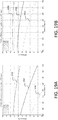
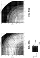
- FIGS. 33A and 33B are plots of the coupling k between a source resonator of the type shown in FIGS. 29A-29D and a device resonator of the type shown in FIGS. 31A-31D , as a function of relative offset between the resonators in the X- and Y-directions.
- FIG. 33A shows the coupling k for a relative offset between the resonators in the Z-direction of 10 cm
- FIG. 33B shows the coupling k for a relative offset between the resonators in the Z-direction of 15 cm.
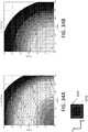
- FIGS. 34A and 34B are plots of the figure-of-merit Uo for a wireless power transfer system that includes a source resonator of the type shown in FIGS. 29A-29D , and a device resonator of the type shown in FIGS. 31A-31D , as a function of relative offset between the resonators in the X- and Y-directions.
- FIG. 34A shows the figure-of-merit Uo for a relative offset between the resonators in the Z-direction of 10 cm
- FIG. 34B shows the figure-of-merit Uo for a relative offset between the resonators in the Z-direction of 15 cm.
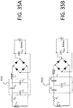
- FIGS. 35A and 35B are schematic diagrams of matching networks for use in device electronics 110.
- FIG. 35A shows a delta capacitor matching network 3502
- FIG. 35B shows a wye capacitor matching network 3504.
- the two capacitor networks are equivalent to each other through a "delta-wye" transformation.
- Delta and wye networks that match a device to an effective impedance that stays relatively flat as a battery voltage and output power vary can be desirable.
- wireless power transfer systems can include a matching network of either topology.
- the implementation of either a delta or wye matching network is guided by the network that uses the fewest capacitors of a given voltage rating, making that network the cheaper of the two to implement.
- FIG. 36 is a plot of the total minimum number of capacitors for delta (3602) and wye (3604) impedance matching networks in a device.
- the device matching point U d can affect the overall efficiency and determine how the power dissipated is distributed between the source and the device. A higher U d value means less power is dissipated in the device and more power is dissipated in the source.
- FIG. 37 is a schematic diagram showing an embodiment of an impedance matching network topology for use in device electronics 110.
- This topology provides additional degrees of freedom in the impedance matching of the device as compared to topologies with fewer component positions. Note that components in positions C b1 and C b2 provide a balancing of the impedance matching network shown in FIG. 35A . Additional aspects of the impedance matching network topology shown in FIG. 37 are disclosed, for example, in U.S. Patent No. 8,461,719 , the entire contents of which are incorporated herein by reference.
- FIG. 38 is a plot of the figure-of-merit U as function of output voltage in a device that includes a receiving resonator with a delta-type impedance matching network (as shown in FIG. 35A ).
- Curve 3802 shows the figure-of-merit U dR which is the resistive component of the device matching impedance for power output of 7.0 kW.
- Curve 3804 shows the figure of merit U dR which is the resistive component of the device matching impedance for power output of 3.5 kW.
- Curve 3806 shows the figure-of-merit U dX which is the reactive component of the device matching impedance for power output of 7.0 kW.
- Curve 3808 shows the figure of merit U dX which is the reactive component of the device matching impedance for power output of 3.5 kW.
- the reactive component of the device matching impedance is generally smaller than the resistive component, and thus the device resonator is not significantly detuned off resonance. Furthermore, in these conditions, current in the source does not increase excessively to drive an off-resonance device resonator.
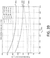
- FIG. 39 is a plot showing the power dissipated in source and receiver resonators that are matched using a delta-type impedance matching network, as a function of output voltage.
- the system of source and receiver resonators has a coupling k of 0.08.
- Curve 3902 shows the power dissipated in the source resonator coil and one or more capacitors of the matching network at a power output of 7.0 kW.
- Curve 3904 shows the power dissipated in the source resonator coil and one or more capacitors of the matching network at a power output of 3.5 kW.
- Curve 3906 shows the power dissipated in the receiver resonator coil and one or more source-side capacitors of the matching network at a power output of 7.0 kW.
- Curve 3908 shows the power dissipated in the receiver resonator coil and one or more device-side capacitors of the matching network at a power output of 3.5 kW.
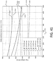
- FIG. 40 is a plot showing the maximum magnetic field in the source and device resonators as a function of output voltage for a wireless power transfer system that includes source and device resonators with a coupling k of 0.08.
- Curve 4002 shows the maximum magnetic field in the source resonator at a power output of 7.0 kW.
- Curve 4004 shows the maximum magnetic field in the source resonator at a power output of 3.5 kW.
- Curve 4006 shows the maximum magnetic field in the device resonator at a power output of 7.0 kW.
- Curve 4008 shows the maximum magnetic field in the device resonator at a power output of 3.5 kW.
- FIG. 41 is a plot showing the voltage across one or more capacitors of a delta-matching network in a receiver resonator of a device (curves 4102-4112) and in a source resonator (curves 4114-4116) as function of output voltage.
- Curve 4102 shows the voltage across capacitor C a in FIG. 37 at a power output of 7.0 kW.
- Curve 4104 shows the voltage across capacitor C a in FIG. 37 at a power output of 3.5 kW.
- Curve 4106 shows the voltage across capacitor C b in FIG. 37 at a power output of 7.0 kW.
- Curve 4108 shows the voltage across capacitor C b in FIG. 37 at a power output of 3.5 kW.
- Curve 4110 shows the voltage across capacitor C c in FIG.
- Curve 4112 shows the voltage across capacitor C c in FIG. 37 at a power output of 3.5 kW.
- Curve 4114 shows the voltage across a source capacitor at a power output of 7.0 kW.
- Curve 4116 shows the voltage across a source capacitor at a power output of 3.5 kW.
- Optimizing impedance matching networks for particular resonator configurations and power delivery specifications involves selecting electronic components for the network.
- one component that is selected is the inductance value L 3 .
- L 3 is too small, the diodes in the rectifier may conduct for only a fraction of an oscillation period, so to transfer a fixed amount of power, the peak current through the diodes would have to be higher, leading to more power dissipation in the diodes.
- the electrical current through L 3 would also peak higher and have more harmonic content, leading to losses in the inductor.
- large values of L 3 can add too much ESR to the impedance matching network. As such, the value of L 3 is chosen to balance these competing effects.
- the peak current is 34.5 A.
- the peak current is 26.7 A.
- the peak current is 19.9 A.
- the peak current is 15.3 A.
- the network configuration can be optimized.
- the device matching point U d affects the overall efficiency of wireless power transfer and how power is dissipated between the source and the device. Higher values of U d mean that more power is dissipated in the source and less is dissipated in the device.
- the optimum configuration for an impedance matching network is generally the configuration that uses the smallest number of capacitors, while satisfying the optimization condition to within an acceptable tolerance.
- FIGS. 66A and 66B are plots showing the number of capacitors in a device's impedance matching network as a function of the inductance of the device's receiving resonator coil inductance, for 800 E series capacitors (American Technical Ceramics Corp.) ( FIG. 66A ) and film capacitors (available from EPCOS, Kunststoff, Germany). Each plot shows results for both delta- and wye-matching networks.
- FIG. 66A corresponds to capacitors at 2000 V peak voltage and 6.6 kW, with a target U d of 50.
- FIG. 66B corresponds to capacitors at 600 V RMS voltage and 6.6 kW, with a target U d of 50.
- FIG. 67 is a schematic diagram of an optimized device impedance matching network.
- C a 28.6 nF (achieved with 5 x 5.1 nF + 1 x 3.0 nF 800 E capacitors)
- C 3 51.0 nF (achieved with 10 x 5.1 nF 800 E series capacitors).
- the total number of capacitors used in the optimized network is 32.
- the optimized network is sufficiently small geometrically that it fits within the empty volume of the "top hat" resonator shown in FIG. 5B .
- FIG. 68 is a plot showing the figure of merit U d as a function of output voltage for an optimized impedance matching network, at a coupling k value of 0.07.
- Curves 6902, 6904, 6906, and 6908 show the power dissipated in the source's resonator coil windings, shield, ferrite magnetic member, and capacitors at 7.0 kW output power.
- Curves 6910, 6912, 6914, and 6916 show the power dissipated in the source's resonator coil windings, shield, ferrite magnetic member, and capacitors at 3.5 kW output power.
- Curves 7002, 7004, 7006, and 7008 show the power dissipated in the device's receiver coil windings, shield, ferrite magnetic member, and capacitors at 7.0 kW output power.
- Curves 7010, 7012, 7014, and 7016 show the power dissipated in the device's receiver coil windings, shield, ferrite magnetic member, and capacitors at 3.5 kW output power.
- Curves 7102 and 7104 show the magnetic field in the magnetic member of the source resonator at 6.6 kW and 3.3 kW power output, respectively.
- Curves 7106 and 7108 show the magnetic field in the magnetic member of the device's receiver resonator at 6.6 kW and 3.3 kW power output, respectively.
- Curves 7202 and 7204 show the voltages across C a at 6.6 kW and 3.3 kW output power, respectively.
- Curves 7206 and 7208 show the voltages across C b at 6.6 kW and 3.3 kW output power, respectively.
- Curves 7210 and 7212 show the voltages across C c at 6.6 kW and 3.3 kW output power, respectively.
- Curves 7302 and 7304 show the current through the source resonator coil at 6.6 kW and 3.3 kW output power, respectively.
- Curves 7306 and 7308 show the current through the device's receiver resonator coil at 6.6 kW and 3.3 kW output power, respectively.
- FIG. 42 is a schematic diagram showing an embodiment of a magnetic member formed from an array of tiles 4202 of magnetic material (e.g., ferrite).
- the ferrite tiles 4202 can have dimensions of about 150 mm by 100 mm, and a thickness of about 5 mm or 8 mm or greater.
- the ferrite tiles 4202 can be arranged such that there are equal gaps of about 0.4 mm between adjacent tiles.
- the maximum dimensions of the magnetic member can be approximately 500 mm by 500 mm.
- the central region of the magnetic member can be left empty (as in FIG. 42 ) or filled with additional magnetic material.
- the magnetic member can be spaced from an aluminum shield 4302 by about 40 mm in a resonator, as shown in FIG. 43 .
- the magnetic member shown in FIGS. 42 and 43 is typically used in a source resonator.
- FIG. 44 shows an image of an embodiment of a source resonator coil 4402 affixed to a magnetic member 4202 positioned over, and spaced from, an aluminum shield 4302.
- the source resonator coil has similar outer dimensions to those of the magnetic member (i.e., about 500 mm x 500 mm), the resonator coil windings span 4404 is approximately 130 mm, and the coil windings have an inner dimension 406 of approximately 240 mm square.
- higher resonator Q values can be achieved by winding multiple resonator coils in parallel within a resonator.
- three coils are wound in parallel with a minimum of 5 loops in each coil to achieve a targeted inductance value.
- FIGS. 45A and 45B are a schematic diagram and an image, respectively, that show an embodiment of a magnetic member formed from an array of ferrite tiles 4502.
- the ferrite tiles 4502 can have dimensions of about 150 mm by 100 mm, with a thickness of about 5 mm or 8 mm or greater.
- the ferrite tiles 4502 can be arranged such that there are equal gaps of about 0.4 mm between the tiles.
- the maximum dimensions of the magnetic member can be approximately 200 mm by 450 mm.
- the magnetic member shown in FIGS. 45A and 45B is typically used in a device's receiver resonator.
- FIG. 46 is an image of an embodiment of a device receiver resonator coil 4602 affixed to a magnetic member 4502.
- the device receiver resonator coil has similar outer dimensions to the magnetic member shown in FIG. 42 (i.e., about 200 mm by 450 mm).
- the receiver resonator coil in FIG. 42 includes a single wire that forms seven loops on the surface of the magnetic member of FIG. 45 .
- the inductance of the receiver resonator coil 4602 is approximately 33.1 ⁇ H and its quality factor is approximately 591.
- FIG. 47A is a schematic diagram of an embodiment of a source resonator coil 4706 affixed to a magnetic member 4704.
- magnetic member 4704 can have dimensions of about 50 cm by 50 cm, and a thickness of about 5 mm, about 8 mm, or greater.
- Coil 4706 and magnetic member 4704 are positioned over, and spaced from, a shield 4702.
- shield 4702 is formed from a conductive material such as aluminum, and has dimensions of about 60 cm by 60 cm).
- gap 4708 between magnetic member 4704 and shield 4702 can be about 50 mm.
- the inductance of coil 4706 can be about 19.9 ⁇ H and its quality factor can be about 1150.
- coil 4706 can include at least three sets of coil windings wound in parallel, each formed from a different wire or conductive material.
- the windings can be connected in parallel to yield a high-Q resonator coil.
- each coil winding can include at least five loops to achieve the target inductance.
- FIG. 47B is a schematic diagram showing an embodiment of a device receiver resonator coil 4716 affixed to magnetic member 4712.
- magnetic member 4712 can have dimensions of about 45 cm by 20 cm, and a thickness of about 5 mm, about 8 mm, or greater.
- a central region of magnetic member 4712 can be stepped such that it protrudes into the region internal to coil 4716, as shown in FIG. 5B .
- the thickness of the magnetic material in the center of the resonator coil can be less than the thickness of the magnetic material elsewhere.
- Coil 4716 and magnetic member 4712 are affixed to a shield 4710 formed of conductive material (e.g., aluminum) and having dimensions of, for example, about 50 cm by 25 cm.
- the inductance of coil 4716 can be 33.3 ⁇ H and its quality factor can be about 443.
- FIG. 48A is a schematic diagram showing an embodiment of a source resonator affixed to a magnetic member 4802 formed from ferrite tiles with dimensions of about 10 cm by 10 cm in each corner, and tiles with dimensions of about 15 cm by 10 cm outside the corners.
- the quality factor of this resonator is approximately 1220.
- FIG. 48B is a schematic diagram showing an embodiment of a source resonator affixed to a magnetic member 4804 formed from ferrite tiles with dimensions of about 15 cm by 10 cm. The quality factor of this resonator is approximately 1050.
- FIG. 49 is an image showing an embodiment of a source resonator 4902 that includes three parallel windings 4904, 4906, and 4908 that are wound in a coil shape and electrically connected in parallel over a magnetic member.
- windings may be electrically connected in parallel instead of series in order to reduce the overall voltage that can occur across the coil. While three windings are shown in FIG. 49 , more generally any number of windings can wound in parallel to form a coil and electrically connected in parallel.
- the windings can have the same or different wire diameters, and the overall shape of the coil formed by the parallel windings can be any of the different shapes disclosed herein.
- two sets of loops - each corresponding to a coil winding - are physically "parallel" if the sets of loops have complementary and corresponding shapes, and the distance between the conductive material forming one set of loops and the conductive material forming the other set of loops is the same between corresponding portions of the sets of loops along 80% or more of the lengths of the conductive materials.
- Two windings may be considered to be physically parallel if the magnetic coupling between the loops of the two windings is greater than 90%.
- sets of parallel loops are frequently interleaved such that corresponding portions of the conductors that form the loops are parallel to one another.
- excess current can flow in the innermost coil winding. This can occur, for example, because the innermost winding typically has a shorter overall length within the coil than middle and outer windings. This is due to the geometry of the windings within the coil - the innermost winding, because it typically has a smaller average loop diameter than the other windings, has a shorter total length, and therefore a smaller total resistance and inductance than the other windings. As a result, excess current can flow in the innermost coil winding relative to the other windings. More generally, because each winding is typically of a different length, the currents that flow in each of the windings are different, and some (or even all) of these may exceed design specifications and/or safety guidelines.
- excess current in any one coil winding may result in decreased efficiency during wireless power transfer due to greater heat dissipation in the winding with excess current.
- heat dissipation increases proportionally with the square of current flow in each parallelized coil winding.
- various methods for balancing currents in multiple parallel windings are disclosed. The general objective underlying these methods is to control current flow in multiple coil windings so that the actual currents that flow in the windings are equal to a predetermined or selected distribution of currents, within an acceptable tolerance range.
- the predetermined distribution of currents is expressed as a percentage of total current flow through the windings that make up the coil. For example, for a coil that includes three parallel windings, the predetermined distribution of current can correspond to 33.3% (i.e., one third) of the total current carried by the coil flowing through each winding.
- the predetermined current distribution corresponds to an equal partitioning of the total current among the windings.
- the predetermined current distribution corresponds to a partitioning of 25% of the total coil current carried by each of the four windings.
- the predetermined distribution does not correspond to an equal partitioning of currents among the windings.
- it can be advantageous to partition the total coil current unequally among the coil's parallel windings.
- the methods and systems disclosed herein can be used flexibly to achieve both equal and non-equal predetermined current distributions among parallel windings of a coil.
- coil windings may be twisted "crossed-over" with one another.
- FIG. 49 shows three such twists at locations 4910, 4912, and 4914.
- the coil windings are crossed in the following manner: at location 4910, winding 4908 is crossed with winding 4906; at location 4912, winding 4908 is crossed with winding 4904; and at location 4914, winding 4906 is crossed with winding 4904.
- three such twists may be sufficient to approximately balance currents throughout the coil.
- the windings of the three coils may be crossed or twisted throughout the coil (e.g., include any number of crossings or twists) to further balance the current in the windings as well as to ensure that each wire is of similar length.
- the twists in the windings may each be separated by a 1/3 of the distance around the coil. More generally, for a coil with n coil windings, the windings can be spaced by 1 / n of the total length of a single winding loop, measured along the loop.
- the crossings between the windings are used to approximately equalize the lengths of the windings.
- each winding has a similar resistance and inductance value, and therefore, an approximately equal portion of the total coil current flows through each of the windings.
- FIG. 50 is a plot showing the magnetic field in the magnetic member of a source resonator (such as the source resonator shown in FIG. 47A ).
- the magnetic member is formed of ferrite of 5 mm thickness.
- the maximum magnetic field is 170 mT at 198 A of current.
- FIG. 51 is a plot showing the magnetic field in the magnetic member of a source resonator (such as the source resonator shown in FIG. 47A ).
- the magnetic member is formed of ferrite of 8 mm thickness.
- the maximum magnetic field is 107 mT at 198 A of current.
- FIG. 52 is a plot showing the magnetic field in the magnetic member of a source resonator (such as the source resonator shown in FIG. 47A ).
- the magnetic member is formed from ferrite tiles of dimension 15 cm by 10 cm by 8 mm.
- the maximum magnetic field is 101 mT at 198 A of current.
- FIG. 53 is a plot showing the magnetic field in the magnetic member of a device resonator (such as the device resonator shown in FIG. 47B ).
- the magnetic member is formed of ferrite of thickness 8 mm.
- FIGS. 54A and 54B are plots showing the magnetic field at a distance of 1 cm above a source resonator having the configuration shown in FIG. 47A .
- FIG. 55 is a plot showing the magnetic field at a distance of 1 cm above a source resonator having the configuration shown in FIG. 47A , plotted on a logarithmic scale.
- currents in parallel windings that form a resonator coil can be balanced by crossing the windings (e.g., using twists) at points along the length of the windings.
- Other methods can also be used to balance currents in multiple parallel coil windings.
- the currents in each of the parallel windings 5602, 5604, 5606 can be balanced using one or more inductors.
- FIGS. 57A and 57B show schematic circuit diagrams of a set of inductors 5702, 5704, 5706 connected in series and used to balance currents in a resonator coil with parallel windings 5602, 5604, and 5606. In some embodiments, as shown in FIG.
- one or more (or even all) of inductors 5702, 5704, 5706 can be tunable.
- the series connected inductors add inductance to the respective windings to which they are connected. By adding suitable amounts of inductance to some or all of the windings, the effective inductance of each winding can be adjusted to achieve a predetermined or target current distribution among the various windings of a coil.
- inductors 5702, 5704, and 5706 can be adjusted based on the measured inductances to balance currents in the parallel windings.
- Inductors 5702, 5704, are 5706 may be referred to as L 1 ⁇ , L 2 ⁇ and L 3 ⁇ , respectively, in the following discussion.
- a variety of adjustable inductors can be used for inductors 5702, 5704, and 5706. Suitable adjustable inductors are disclosed, for example, in U.S. Patent Application Publication No. 2015/0051750 .
- the methods discussed below can be performed during the manufacturing phase of a resonator, so that inductors with suitable inductance values can be included in a resonator at time of fabrication. That is, the methods can be performed with the goal of selecting and/or adjusting inductors connected in series with parallel coil windings so that when manufacturing of the resonator is complete, the inductances of the coil windings have been adjusted to achieve a particular predetermined partitioning of the total coil current among the windings. As discussed above, the partitioning can correspond to a nominally equal distribution of current among the windings, but can also correspond to an unequal distribution of current.
- the methods according to the invention are performed post-manufacture by an electronic processor that is part of, or connected to, the resonator.
- the electronic processor can be configured to determine As discussed above, in some embodiments, currents in parallel windings that form a resonator coil can be balanced by crossing the windings (e.g., using twists) at points along the length of the windings. Other methods can also be used to balance currents in multiple parallel coil windings. In particular, referring to FIG. 56 for example, the currents in each of the parallel windings 5602, 5604, 5606 can be balanced using one or more inductors. FIGS.
- 57A and 57B show schematic circuit diagrams of a set of inductors 5702, 5704, 5706 connected in series and used to balance currents in a resonator coil with parallel windings 5602, 5604, and 5606.
- one or more (or even all) of inductors 5702, 5704, 5706 can be tunable.
- the series connected inductors add inductance to the respective windings to which they are connected. By adding suitable amounts of inductance to some or all of the windings, the effective inductance of each winding can be adjusted to achieve a predetermined or target current distribution among the various windings of a coil.
- inductors 5702, 5704, and 5706 can be adjusted based on the measured inductances to balance currents in the parallel windings.
- Inductors 5702, 5704, are 5706 may be referred to as L 1 ⁇ , L 2 ⁇ and L 3 ⁇ , respectively, in the following discussion.
- a variety of adjustable inductors can be used for inductors 5702, 5704, and 5706. Suitable adjustable inductors are disclosed, for example, in U.S. Patent Application Publication No. 2015/0051750 , the entire contents of which are incorporated herein by reference.
- the methods discussed below can be performed during the manufacturing phase of a resonator, so that inductors with suitable inductance values can be included in a resonator at time of fabrication. That is, the methods can be performed with the goal of selecting and/or adjusting inductors connected in series with parallel coil windings so that when manufacturing of the resonator is complete, the inductances of the coil windings have been adjusted to achieve a particular predetermined partitioning of the total coil current among the windings. As discussed above, the partitioning can correspond to a nominally equal distribution of current among the windings, but can also correspond to an unequal distribution of current.
- the methods can also be performed post-manufacture by an electronic processor that is part of, or connected to, the resonator.
- the electronic processor can be configured to determine suitable inductance values of adjustable inductors once in a single optimization sequence.
- the processor can be configured to repeat the steps discussed below multiple times (e.g., at predetermined time intervals and/or in response to a user signal) for purposes such as calibration and re-calibration, in response to changes in the operating environment and/or parameters of a resonator.
- the discussion below describes various steps that an electronic processor can perform. It should be appreciated that these steps can be performed pre- and/or post-fabrication of a resonator coil, and also that certain steps can be performed during the design phase by a human.
- FIG. 74 is a flow chart 7400 that includes a series of steps for balancing currents in parallel windings of a resonator coil.
- FIG. 74 the three parallel windings 1, 2, and 3 above are referenced. More generally, however, it should be understood that the methods disclosed herein can be used to balance currents in any number of parallel windings that form a resonator coil.
- the electronic processor determines the inductance matrix L of the three connected windings, represented by inductance values L 1 , L 2 , and L 3 .
- L 1 ⁇ L 2 ⁇ L 3 to accommodate parallel windings in which L 1 is the innermost winding, L 2 is the middle winding, and L 3 is the outermost winding.
- the components of the inductance matrix L can be obtained directly by measuring the coupling between the windings (e.g., using an inductance sensor connected to the electronic processor, not shown in FIG. 56 ).
- the electronic processor is configured to receive coupling (i.e., inductance) measurements from the sensor, and to determine values of the diagonal elements in matrix L based on the measurements.
- the diagonal elements in L correspond to each winding's inductance measured when the other windings are open-circuited by the electronic processor.
- L 1 21.9 ⁇ H
- L 2 23.0 ⁇ H
- L 3 23.7 ⁇ H
- l 1,2 5.24 ⁇ H
- l 1,3 635 ⁇ H
- l 2,3 5.61 ⁇ H
- This current repartition corresponds to the following relative repartition of the total current among the three windings: (48.45%, 25.36%, 26.19%).
- current I 1 is nearly twice as large as I 2 or I 3 .
- the electronic processor determines the desired or target current repartition among the windings.
- the target current repartition can be a set of stored values retrieved from a memory or data storage unit, a set of values supplied by a user, or a hard-coded or fixed implementation in circuitry.
- the target current repartition represents the performance condition that the electronic processor attempts to achieve by adjusting individual inductances coupled to the coil windings.
- the target repartition corresponds to an equal division of the total current among the windings. This example will be discussed in more detail below. More generally, however, the methods and systems disclosed herein can achieve any target repartition of the total current among the windings.
- flow chart 7400 involved three windings 1, 2, and 3 and an even current repartition by way of example. More generally, however, the methods for current balancing shown in flow chart 7400 can be applied to coils with any number n of parallel windings, and to target a desired current repartition between these windings. Thus, for a coil with n parallel windings electrically connected in parallel, the following steps can be performed by the electronic processor to balance currents in each of the windings.
- the electronic processor determines the inductance matrix L of the n windings.
- the components of L can be obtained directly by measuring the coupling (i.e., inductances) between the windings.
- the diagonal elements in matrix L are each connected winding's inductance measured when the other windings are open-circuited.
- step 7404 the electronic processor determines the desired or target repartition of the total current among the coil windings.
- the added inductances L i ⁇ can be implemented so that they do not couple magnetically with any of the n windings nor with one another. Because there is no cross-coupling, the inductances L i ⁇ are added along the diagonal of the L matrix, leaving the other elements of L unchanged.
- combinations of inductances L i ⁇ , ... , L n ⁇ that yield approximately equal current repartition in the n windings may be more easily found with the addition of large inductor values.
- the added inductances L i ⁇ , ... , L n ⁇ can be much larger than the inductances of the windings.
- the added inductances L 1 ⁇ , ... , L n ⁇ are much larger than the most inductive winding, a near-perfect current splitting can result. However, this may not be useful from a practical standpoint.
- the number of windings n may be limited due to the space constraints placed on the overall size of the source resonator coil.
- the range of values for L 1 ⁇ , ... , L n ⁇ may be constrained to be less than or equal to the scaled inductance of the windings: L i ⁇ ⁇ a l i where a is a scalar between zero and the difference between the maximum inductance of a winding and the minimum inductance of a winding.
- the number of windings m to which additional inductance is added can be determined by the electronic processor.
- the number of windings to which additional inductance is added may be limited to be less than or equal to the total number of windings n.
- the number of windings m to which additional inductance is added can be determined before optimizing the current distribution over the n windings.
- different combinations of the number of windings m to which additional inductance is added can be iteratively selected during the current distribution optimization.
- the one winding where no inductor is added is the one that has the largest inductance.
- inductors can be added to the winding that have the lowest inductance and leave the n - m windings with the largest inductance without additional inductors for current balancing.
- an electronic processor can control the adding of inductors based on changes to the order of inductance of the windings depending on external factors (presence of a device, presence of lossy materials, etc.).
- the electronic processor can optimize the combination of additional inductances L 1 ⁇ , L 2 ⁇ , L 3 ⁇ that minimizes: I 1 ⁇ 1 ⁇ I 3 2
- I 3 ⁇ 1 ⁇ I 3 2 where ⁇ I I 1 ⁇ + I 2 ⁇ + I 3 ⁇ .
- the electronic processor can then compare the three configurations to determine which additional inductor, L 1 ⁇ , L 2 ⁇ , or L 3 ⁇ , yields the best results in terms of current distribution (or another metric).
- a single inductor 5702 can be used to yield approximately equal current repartition among multiple parallel coil windings.
- the optimization can be performed iteratively by the electronic processor until the current distribution in each of the windings is within 20% (e.g., within 15%, within 10%, within 5%) of a target current distribution, which can be (but need not be) an equal current distribution among the windings.
- a target current distribution which can be (but need not be) an equal current distribution among the windings.
- a slightly reduced current in outermost winding 5606 can be advantageous, since the longer length of winding 5606 yields a resistance that can be about 8% higher than the resistance of the other windings.
- one of the windings may be less effectively cooled compared to other windings and thus, current repartition may be changed accordingly.
- some windings may have a different than expected resistance or inductance at the time of manufacture and an electronic processor may be able to compensate for these differences.
- inductor L 1 ⁇ can include a pair of cores formed from magnetic material.
- an inductor with a planar E-core formed of ferrite can be used.
- Inductor L 1 ⁇ can be wound with the same Litz wire as the innermost winding (winding 5602) and can therefore simplify the connection.
- the following current repartition is achieved:
- the memory 7504 can store information about optimized parameters of the system.
- the information can include optimized impedance matching conditions for various levels of power output from the power source.
- the memory 7504 can store information such as resonant frequencies of resonator and magnetic properties (e.g., magnetic permeability depending on power levels) of magnetic components in the system, which can be used by the processor 7502 for determining signals to be sent out to control various elements in the system.
- the memory can also store a set of values corresponding to a target current repartition.
- the storage device 7506 can be a computer-readable medium, such as a floppy disk device, a hard disk device, an optical disk device, or a tape device, a flash memory or other similar solid state memory device, or an array of devices, including devices in a storage area network or other configurations.
- the storage device 7506 can store instructions that can be executed by processor 7502 described above. In certain embodiments, the storage device 7506 can store information described in relation to memory 7504.
- electronic controller 7503 can include a graphics processing unit to display graphical information (e.g., using a GUI or text interface) on an external input/output device, such as display 7516.
- the graphical information can be displayed by a display device (e.g., a CRT (cathode ray tube) or LCD (liquid crystal display) monitor) for displaying information.
- a display device e.g., a CRT (cathode ray tube) or LCD (liquid crystal display) monitor
- input devices e.g., keyboard, pointing device, touch screen, speech recognition device
- the user can monitor the display 7516 to analyze the power transfer conditions of the system.
- the user can adjust parameters (e.g., power transfer level, capacitor values in impedance matching networks, operation frequency of power source, resonant frequencies of resonators) by inputting information through the input devices.
- parameters e.g., power transfer level, capacitor values in impedance matching networks, operation frequency of power source, resonant frequencies of resonators
- the electronic controller 7503 can control the system as described above.
- the electronic controller 7503 can monitor hazardous conditions of the system. For example, the electronic controller 7503 can detect over-heating in the system and provide an alert (e.g., visual and/or audible alert) to the user through its graphical display or audio device.
- an alert e.g., visual and/or audible alert
- electronic controller 7503 can be used to control magnitudes and phases of currents flowing in one or more coils of the wireless power transfer system.
- processor 7502 can calculate and determine the magnitudes and phase of currents to be supplied to coils in a power transmitting apparatus. The determination can be based on the monitored power transfer efficiency and information stored in memory 7504 or storage unit 7506.
- a feedback signal can be received and processed by the electronic controller 7503.
- the electronic controller 7503 can include a wireless communication device (e.g., radio-frequency, Bluetooth receiver) to receive information from either or both of a power transmitting apparatus and a power receiving apparatus (which can have its own wireless communication device).
- the received information can be processed by processor 7502, which can further send out control signals to adjust parameters of the system as described above.
- the control signals can be used to adjust the magnitudes and phases of currents flowing in one or more coils of resonators in the system to increase the power transfer efficiency.
- Various embodiments of the systems and techniques described here can be realized by one or more computer programs that are executable and/or interpretable on the electronic controller 7503.
- These computer programs include machine instructions for a programmable processor, and can be implemented in a high-level procedural and/or object-oriented programming language, and/or in assembly/machine language.
- computer programs can contain the instructions that can be stored in memory 7504 and storage unit 7506 and executed by processor 7502 as described above.
- computer-readable medium refers to any computer program product, apparatus and/or device (e.g., magnetic discs, optical disks, memory, Programmable Logic Devices (PLDs)) used to provide machine instructions and/or data to a programmable processor, including a machine-readable medium that receives machine instructions.
- PLDs Programmable Logic Devices
- electronic controller 7503 can be implemented in a computing system to implement the operations described above.
- the computing system can include a back end component (e.g., as a data server), or a middleware component (e.g., an application server), or a front end component (e.g., a client computer having a graphical user-interface), or any combination therefor, to allow a user to utilized the operations of the electronic controller 7503.
- a back end component e.g., as a data server
- middleware component e.g., an application server
- a front end component e.g., a client computer having a graphical user-interface
- the electronic controller 7503 or one or more of its elements can be integrated in a vehicle.
- the electronic controller 7503 can be utilized to control and/or monitor wireless power charging of a battery installed in the vehicle.
- the display 7516 can be installed adjacent to the driving wheel of the vehicle so that a user may monitor conditions of the power charging and/or control parameters of the power charging as described in relation to FIG. 75 .
- the display 7516 can also visualize information traffic information and road maps based on Global Positioning System (GPS) information. Any of the elements such as the processor 7502, memory 7504 and storage device 7506 can be installed in the space behind the display 7516, which can visualize the data process by those elements.
- GPS Global Positioning System
Claims (15)
- System zur drahtlosen Stromübertragung, aufweisend:einen Resonator, der eine Spule mit mindestens zwei Wicklungen (5602, 5604, 5606) aufweist, wobei jede der mindestens zwei Wicklungen mehrere Schleifen aufweist, die durch ein leitendes Material gebildet sind und sich in einer Ebene erstrecken, wobei entsprechende Abschnitte aller der mindestens zwei Wicklungen parallel ausgerichtet sind, wobei mindestens eine der Wicklungen eine Länge aufweist, die sich von einer Länge einer anderen Wicklung unterscheidet, und wobei die mindestens zwei Wicklungen elektrisch parallel geschaltet sind; undmindestens eine Induktivität (5702, 5704, 5706), die einen Induktivitätswert aufweist, wobei die mindestens eine Induktivität mit mindestens einer der Wicklungen in Reihe geschaltet ist,wobei der Induktivitätswert so gewählt ist, dass, wenn die Spule während des Betriebs des Systems einen Strom führt, die mindestens eine Induktivität eine Verteilung der Stromflüsse zwischen den mindestens zwei Wicklungen aufrechterhält, so dass sich für jede der mindestens zwei Wicklungen ein Ist-Stromfluss in der Wicklung von einem Soll-Stromfluss für die Wicklung um 10% oder weniger unterscheidet,dadurch gekennzeichnet, dass:
die mindestens eine Induktivität einen einstellbaren Induktivitätswert aufweist, der während des Betriebs des Systems durch einen elektronischen Prozessor einstellbar ist. - System nach Anspruch 1, wobei entsprechende Abschnitte aller der mindestens zwei Wicklungen entlang mindestens 80% einer Länge mindestens einer der Wicklungen parallel ausgerichtet sind.
- System nach Anspruch 1, wobei die Schleifen jeder Wicklung verschachtelt sind.
- System nach Anspruch 1, wobei die Schleifen jeder Wicklung konzentrisch sind und eine Spirale bilden.
- System nach Anspruch 1, ferner aufweisend einen elektronischen Prozessor (105, 111, 7502), der mit den mindestens zwei Wicklungen gekoppelt ist und dazu ausgelegt ist, elektrische Ströme in den einzelnen Wicklungen basierend auf den Soll-Stromflüssen für die mindestens zwei Wicklungen zu steuern.
- System nach Anspruch 5, wobei der elektronische Prozessor dazu ausgelegt ist, elektrische Ströme in den einzelnen Wicklungen zu steuern durch:Bestimmen eines Soll-Induktivitätswerts für die mindestens einen Induktivität basierend auf einer Gütezahl, die mit den Soll-Stromflüssen in Beziehung steht; undEinstellen des Induktivitätswerts der mindestens einen Induktivität, um dem Soll-Induktivitätswert zu entsprechen.
- System nach Anspruch 6, wobei der elektronische Prozessor dazu ausgelegt ist, den Soll-Induktivitätswert zu bestimmen durch:(i) für jede der Wicklungen:Bestimmen eines Selbstinduktivitätswerts der einen Wicklung basierend auf einer Messung der Induktivität der einen Wicklung, wenn sie elektrisch von allen anderen Wicklungen getrennt ist; undBestimmen von mehreren Gegeninduktivitätswerten der einen Wicklung, wobei jeder Gegeninduktivitätswert auf einer Messung der Induktivität der einen Wicklung basiert, wenn sie von einer anderen der Wicklungen elektrisch getrennt ist;(ii) Bestimmen der Soll-Stromflüsse für jede der Wicklungen basierend auf den Selbstinduktivitätswerten und den Gegeninduktivitätswerten; und(iii) Bestimmen des Soll-Induktivitätswerts basierend auf den Soll-Stromflüssen für jede der Wicklungen.
- System nach Anspruch 7, wobei der elektronische Prozessor dazu ausgelegt ist, den Soll-Stromfluss zu bestimmen durch:Konstruieren einer Induktivitätsmatrix basierend auf den Selbstinduktivitätswerten und den Gegeninduktivitätswerten jeder der Wicklungen;Berechnen einer Matrix von eingestellten Induktivitäten durch Addieren, zu der Induktivitätsmatrix, einer Induktivität-Modifizierungs-Matrix, die Elemente aufweist, die Änderungen der Induktivität jeder der Wicklungen aufgrund der mindestens einen Induktivität entsprechen;Berechnen einer inversen Matrix der Matrix von eingestellten Induktivitäten; und Bestimmen der Soll-Stromflüsse basierend auf der inversen Matrix.
- System nach Anspruch 8, wobei die Induktivitäts-Modifizierungs-Matrix eine diagonale Matrix ist, und wobei Diagonalelemente der Induktivitäts-Modifizierungs-Matrix Induktivitätswerte von jeweiligen Elementen der mindestens einen Induktivität, die mit den Wicklungen verbunden ist, sind.
- System nach einem der vorhergehenden Ansprüche, wobei die Verteilung von Strömen keiner gleichmäßigen Verteilung von Strömen zwischen den Wicklungen entspricht.
- Verfahren, aufweisend:Steuern elektrischer Ströme in jeder von mindestens zwei Wicklungen (5602, 5604, 5606) einer Resonatorspule zur drahtlose Stromübertragung eines Systems zur drahtlosen Stromübertragung,wobei jede der mindestens zwei Wicklungen mehrere Schleifen aufweist, die durch ein leitendes Material gebildet sind und sich in einer Ebene erstrecken, wobei entsprechende Abschnitte jeder der mindestens zwei Wicklungen parallel ausgerichtet sind, wobei mindestens eine der Wicklungen eine Länge aufweist, die sich von einer Länge einer anderen der Wicklungen unterscheidet, wobei die mindestens zwei Wicklungen elektrisch parallel geschaltet sind, und wobei mindestens eine Induktivität (5702, 5704, 5706), die einen Induktivitätswert aufweist, mit mindestens einer der Wicklungen in Reihe geschaltet ist; undAufrechterhalten einer Verteilung der Stromflüsse zwischen den mindestens zwei Wicklungen, wenn die Spule einen Strom führt, so dass sich für jede der mindestens zwei Wicklungen ein Ist-Stromfluss in der Wicklung von einem Soll-Stromfluss für die Wicklung um 10% oder weniger unterscheidet, durch Einstellen eines einstellbaren Induktivitätswerts der mindestens einen Induktivität durch einen elektronischen Prozessor während des Betriebs des Systems.
- Verfahren nach Anspruch 11, ferner aufweisend Steuern, durch einen Prozessor des Systems zur drahtlosen Stromübertragung, von elektrischen Strömen in jeder der Wicklungen, um die Verteilung der Stromflüsse aufrechtzuerhalten durch:Bestimmen eines Soll-Induktivitätswerts für die mindestens eine Induktivität basierend auf einer Gütezahl, die mit den Soll-Stromflüssen in Beziehung steht; undEinstellen des Induktivitätswerts der mindestens einen Induktivität, um dem Soll-Induktivitätswert zu entsprechen.
- Verfahren nach Anspruch 12, ferner aufweisend Bestimmen, durch den Prozessor, des Soll-Induktivitätswerts durch:(i) für jede der Wicklungen:Bestimmen eines Selbstinduktivitätswerts der einen Wicklung basierend auf einer Messung der Induktivität der einen Wicklung, wenn sie elektrisch von allen anderen Wicklungen getrennt ist; und
Bestimmen von mehreren Gegeninduktivitätswerten der einen Wicklung, wobei jeder Gegeninduktivitätswert auf einer Messung der Induktivität der einen Wicklung basiert, wenn sie von einer anderen der Wicklungen elektrisch getrennt ist;(ii) Bestimmen der Soll-Stromflüsse für jede der Wicklungen basierend auf den Selbstinduktivitätswerten und den Gegeninduktivitätswerten; und(iii) Bestimmen des Soll-Induktivitätswerts basierend auf den Soll-Stromflüssen für jede der Wicklungen. - Verfahren nach Anspruch 13, ferner aufweisend Bestimmen, durch den Prozessor, der Soll-Stromflüsse durch:Konstruieren einer Induktivitätsmatrix basierend auf den Selbstinduktivitätswerten und den Gegeninduktivitätswerten jeder der Wicklungen;Berechnen einer Matrix von eingestellten Induktivitäten durch Addieren, zu der Induktivitätsmatrix, einer Induktivitäts-Modifizierungs-Matrix, die Elemente aufweist, die Änderungen der Induktivität jeder der Wicklungen aufgrund der mindestens einen Induktivität entsprechen;Berechnen einer inversen Matrix der Matrix von eingestellten Induktivitäten; und Bestimmen der Soll-Stromflüsse basierend auf der inversen Matrix.
- Verfahren nach Anspruch 14, wobei die Induktivitäts-Modifizierungs-Matrix eine Diagonalmatrix ist und wobei Diagonalelemente der Induktivitäts-Modifizierungs-Matrix Induktivitätswerte von jeweiligen Elementen der mindestens einen Induktivität, die mit den Wicklungen verbunden ist, sind.
Applications Claiming Priority (3)
| Application Number | Priority Date | Filing Date | Title |
|---|---|---|---|
| US201462022133P | 2014-07-08 | 2014-07-08 | |
| US201462051647P | 2014-09-17 | 2014-09-17 | |
| PCT/US2015/039612 WO2016007674A1 (en) | 2014-07-08 | 2015-07-08 | Resonator balancing in wireless power transfer systems |
Publications (2)
| Publication Number | Publication Date |
|---|---|
| EP3167532A1 EP3167532A1 (de) | 2017-05-17 |
| EP3167532B1 true EP3167532B1 (de) | 2018-10-17 |
Family
ID=53673321
Family Applications (1)
| Application Number | Title | Priority Date | Filing Date |
|---|---|---|---|
| EP15738810.9A Active EP3167532B1 (de) | 2014-07-08 | 2015-07-08 | Resonatorausgleich in systemen zur drahtlosen stromübertragung |
Country Status (5)
| Country | Link |
|---|---|
| US (1) | US9842688B2 (de) |
| EP (1) | EP3167532B1 (de) |
| JP (1) | JP6518316B2 (de) |
| CN (1) | CN107258046B (de) |
| WO (1) | WO2016007674A1 (de) |
Families Citing this family (22)
| Publication number | Priority date | Publication date | Assignee | Title |
|---|---|---|---|---|
| US9793720B2 (en) | 2014-04-16 | 2017-10-17 | The Regents Of The University Of Michigan | Wireless power transfer using multiple near-field plates |
| US10114120B2 (en) | 2014-04-16 | 2018-10-30 | The Regents Of The University Of Michigan | Unidirectional near-field focusing using near-field plates |
| US9837860B2 (en) * | 2014-05-05 | 2017-12-05 | Witricity Corporation | Wireless power transmission systems for elevators |
| JP6172185B2 (ja) * | 2015-03-11 | 2017-08-02 | トヨタ自動車株式会社 | 受電装置および送電装置 |
| JP2017034029A (ja) * | 2015-07-30 | 2017-02-09 | 日本特殊陶業株式会社 | 共振器 |
| TWI565187B (zh) * | 2015-09-15 | 2017-01-01 | 至美科技股份有限公司 | Llc充電器及其控制方法與發射-接收變壓器 |
| US10714960B2 (en) * | 2015-12-22 | 2020-07-14 | Intel Corporation | Uniform wireless charging device |
| KR101847256B1 (ko) * | 2016-01-11 | 2018-05-28 | 한국전자통신연구원 | 무선전력 수신장치, 그를 포함하는 무선전력 전송 시스템 및 수신단의 유효부하저항 변환비율을 자동으로 제어하는 방법 |
| US9837923B2 (en) * | 2016-04-27 | 2017-12-05 | General Electric Company | Integrated power converter and transformer |
| JP6532086B2 (ja) * | 2016-04-28 | 2019-06-19 | 昭和飛行機工業株式会社 | 外部磁気遮蔽式の非接触給電装置 |
| US10726991B2 (en) | 2016-05-18 | 2020-07-28 | Nissan Motor Co., Ltd. | Coil unit for contactless power supply |
| WO2018097739A1 (en) | 2016-11-25 | 2018-05-31 | Auckland Uniservices Limited | Current distribution and thermal regulation in inductive power transfer coupling structures |
| US10984946B2 (en) | 2016-12-20 | 2021-04-20 | Witricity Corporation | Reducing magnetic flux density proximate to a wireless charging pad |
| JP7285784B2 (ja) | 2017-03-17 | 2023-06-02 | エフィシエント パワー コンヴァーション コーポレーション | 大面積スケーラブル高共振ワイヤレス電力コイル |
| US10469119B2 (en) * | 2017-05-25 | 2019-11-05 | Spigen Korea Co., Ltd. | Magnetic mount for electronic devices |
| US11283296B2 (en) | 2017-05-26 | 2022-03-22 | Nucurrent, Inc. | Crossover inductor coil and assembly for wireless transmission |
| US10819156B2 (en) | 2017-12-05 | 2020-10-27 | Witricity Corporation | Flush-mount wireless charging power-transfer system |
| US10855118B2 (en) * | 2018-06-22 | 2020-12-01 | Apple Inc. | Electric shielding structures |
| US11283303B2 (en) | 2020-07-24 | 2022-03-22 | Nucurrent, Inc. | Area-apportioned wireless power antenna for maximized charging volume |
| CN112260540B (zh) * | 2020-10-19 | 2021-10-08 | 山东大学 | 一种谐振直流变换器并联均流方法及系统 |
| US11695302B2 (en) * | 2021-02-01 | 2023-07-04 | Nucurrent, Inc. | Segmented shielding for wide area wireless power transmitter |
| US20230261570A1 (en) * | 2022-02-11 | 2023-08-17 | Applied Materials, Inc. | Tunable integrated voltage regulator |
Family Cites Families (584)
| Publication number | Priority date | Publication date | Assignee | Title |
|---|---|---|---|---|
| US645576A (en) | 1897-09-02 | 1900-03-20 | Nikola Tesla | System of transmission of electrical energy. |
| US787412A (en) | 1900-05-16 | 1905-04-18 | Nikola Tesla | Art of transmitting electrical energy through the natural mediums. |
| GB190508200A (en) | 1905-04-17 | 1906-04-17 | Nikola Tesla | Improvements relating to the Transmission of Electrical Energy. |
| US1119732A (en) | 1907-05-04 | 1914-12-01 | Nikola Tesla | Apparatus for transmitting electrical energy. |
| US2133494A (en) | 1936-10-24 | 1938-10-18 | Harry F Waters | Wirelessly energized electrical appliance |
| US3535543A (en) | 1969-05-01 | 1970-10-20 | Nasa | Microwave power receiving antenna |
| US3517350A (en) | 1969-07-07 | 1970-06-23 | Bell Telephone Labor Inc | Energy translating device |
| GB1303835A (de) | 1970-01-30 | 1973-01-24 | ||
| US3871176A (en) | 1973-03-08 | 1975-03-18 | Combustion Eng | Large sodium valve actuator |
| US4088999A (en) | 1976-05-21 | 1978-05-09 | Nasa | RF beam center location method and apparatus for power transmission system |
| US4095998A (en) | 1976-09-30 | 1978-06-20 | The United States Of America As Represented By The Secretary Of The Army | Thermoelectric voltage generator |
| JPS5374078A (en) | 1976-12-14 | 1978-07-01 | Bridgestone Tire Co Ltd | Device for warning pressure reducing of inner pressure of tire |
| US4280129A (en) | 1978-09-09 | 1981-07-21 | Wells Donald H | Variable mutual transductance tuned antenna |
| US4450431A (en) | 1981-05-26 | 1984-05-22 | Hochstein Peter A | Condition monitoring system (tire pressure) |
| US4588978A (en) | 1984-06-21 | 1986-05-13 | Transensory Devices, Inc. | Remote switch-sensing system |
| DE301127T1 (de) | 1987-07-31 | 1989-08-24 | Texas Instruments Deutschland Gmbh, 8050 Freising, De | Transponder-anordnung. |
| DE3815114A1 (de) | 1988-05-04 | 1989-11-16 | Bosch Gmbh Robert | Vorrichtung zur uebertragung und auswertung von messsignalen fuer den reifendurck von kraftfahrzeugen |
| DE3824972A1 (de) | 1988-07-22 | 1989-01-12 | Roland Hiering | Weihnachtsbaum-, dekorations-, kunstwerk- und schmuckbeleuchtung |
| JPH0297005A (ja) | 1988-10-03 | 1990-04-09 | Tokyo Cosmos Electric Co Ltd | 可変インダクタンス |
| JP2820706B2 (ja) | 1989-03-02 | 1998-11-05 | 株式会社日本自動車部品総合研究所 | 電磁結合用のコイルを有する電力供給装置 |
| US5034658A (en) | 1990-01-12 | 1991-07-23 | Roland Hierig | Christmas-tree, decorative, artistic and ornamental object illumination apparatus |
| US5027709A (en) | 1990-04-26 | 1991-07-02 | Slagle Glenn B | Magnetic induction mine arming, disarming and simulation system |
| JPH04265875A (ja) | 1991-02-21 | 1992-09-22 | Seiko Instr Inc | 平面型グラジオメータ |
| US5293308A (en) | 1991-03-26 | 1994-03-08 | Auckland Uniservices Limited | Inductive power distribution system |
| US6738697B2 (en) | 1995-06-07 | 2004-05-18 | Automotive Technologies International Inc. | Telematics system for vehicle diagnostics |
| US5118997A (en) | 1991-08-16 | 1992-06-02 | General Electric Company | Dual feedback control for a high-efficiency class-d power amplifier circuit |
| NL9101590A (nl) | 1991-09-20 | 1993-04-16 | Ericsson Radio Systems Bv | Stelsel voor het laden van een oplaadbare accu van een draagbare eenheid in een rek. |
| US5341083A (en) | 1991-09-27 | 1994-08-23 | Electric Power Research Institute, Inc. | Contactless battery charging system |
| GB2262634B (en) | 1991-12-18 | 1995-07-12 | Apple Computer | Power connection scheme |
| US5216402A (en) | 1992-01-22 | 1993-06-01 | Hughes Aircraft Company | Separable inductive coupler |
| US5229652A (en) | 1992-04-20 | 1993-07-20 | Hough Wayne E | Non-contact data and power connector for computer based modules |
| WO1993023908A1 (en) | 1992-05-10 | 1993-11-25 | Auckland Uniservices Limited | A non-contact power distribution system |
| US5437057A (en) | 1992-12-03 | 1995-07-25 | Xerox Corporation | Wireless communications using near field coupling |
| US5287112A (en) | 1993-04-14 | 1994-02-15 | Texas Instruments Incorporated | High speed read/write AVI system |
| GB9310545D0 (en) | 1993-05-21 | 1993-07-07 | Era Patents Ltd | Power coupling |
| JP3207294B2 (ja) | 1993-06-02 | 2001-09-10 | 株式会社安川電機 | 自在油圧装置 |
| JP3409145B2 (ja) | 1993-07-26 | 2003-05-26 | 任天堂株式会社 | 小型電気機器 |
| US5541604A (en) | 1993-09-03 | 1996-07-30 | Texas Instruments Deutschland Gmbh | Transponders, Interrogators, systems and methods for elimination of interrogator synchronization requirement |
| AU8006494A (en) | 1993-10-21 | 1995-05-08 | John Talbot Boys | A flux concentrator for an inductive power transfer system |
| US5408209A (en) | 1993-11-02 | 1995-04-18 | Hughes Aircraft Company | Cooled secondary coils of electric automobile charging transformer |
| US5565763A (en) | 1993-11-19 | 1996-10-15 | Lockheed Martin Corporation | Thermoelectric method and apparatus for charging superconducting magnets |
| US5493691A (en) | 1993-12-23 | 1996-02-20 | Barrett; Terence W. | Oscillator-shuttle-circuit (OSC) networks for conditioning energy in higher-order symmetry algebraic topological forms and RF phase conjugation |
| US5957956A (en) | 1994-06-21 | 1999-09-28 | Angeion Corp | Implantable cardioverter defibrillator having a smaller mass |
| US6459218B2 (en) | 1994-07-13 | 2002-10-01 | Auckland Uniservices Limited | Inductively powered lamp unit |
| EP0786165A1 (de) | 1994-07-13 | 1997-07-30 | Auckland Uniservices Limited | Induktiv gespeiste beleuchtung |
| US5522856A (en) | 1994-09-20 | 1996-06-04 | Vitatron Medical, B.V. | Pacemaker with improved shelf storage capacity |
| JPH08191259A (ja) | 1995-01-11 | 1996-07-23 | Sony Chem Corp | 非接触式icカードシステム用送受信装置 |
| US5710413A (en) | 1995-03-29 | 1998-01-20 | Minnesota Mining And Manufacturing Company | H-field electromagnetic heating system for fusion bonding |
| US5697956A (en) | 1995-06-02 | 1997-12-16 | Pacesetter, Inc. | Implantable stimulation device having means for optimizing current drain |
| WO1997000144A1 (fr) | 1995-06-16 | 1997-01-03 | Daicel Chemical Industries, Ltd. | Procede de differenciation entre generateurs de gaz pour coussins gonflables utilises et inutilises lors de la mise a la ferraille de voitures |
| US5703461A (en) | 1995-06-28 | 1997-12-30 | Kabushiki Kaisha Toyoda Jidoshokki Seisakusho | Inductive coupler for electric vehicle charger |
| US5703950A (en) | 1995-06-30 | 1997-12-30 | Intermec Corporation | Method and apparatus for controlling country specific frequency allocation |
| US5630835A (en) | 1995-07-24 | 1997-05-20 | Cardiac Control Systems, Inc. | Method and apparatus for the suppression of far-field interference signals for implantable device data transmission systems |
| EP0782214B1 (de) | 1995-12-22 | 2004-10-06 | Texas Instruments France | Ringantennen für Resonanzschaltkreise |
| JPH09182323A (ja) | 1995-12-28 | 1997-07-11 | Rohm Co Ltd | 非接触式電力伝達装置 |
| DE69711963T2 (de) | 1996-01-30 | 2002-11-28 | Sumitomo Wiring Systems | Verbindungssystem und -verfahren für ein elektrisch betriebenes Fahrzeug |
| US6066163A (en) | 1996-02-02 | 2000-05-23 | John; Michael Sasha | Adaptive brain stimulation method and system |
| US6108579A (en) | 1996-04-15 | 2000-08-22 | Pacesetter, Inc. | Battery monitoring apparatus and method for programmers of cardiac stimulating devices |
| JPH09298847A (ja) | 1996-04-30 | 1997-11-18 | Sony Corp | 非接触充電器 |
| US5926949A (en) | 1996-05-30 | 1999-07-27 | Commscope, Inc. Of North Carolina | Method of making coaxial cable |
| US5821728A (en) | 1996-07-22 | 1998-10-13 | Schwind; John P. | Armature induction charging of moving electric vehicle batteries |
| JPH1092673A (ja) | 1996-07-26 | 1998-04-10 | Tdk Corp | 非接触電力伝送装置 |
| US5836943A (en) | 1996-08-23 | 1998-11-17 | Team Medical, L.L.C. | Electrosurgical generator |
| US6832735B2 (en) | 2002-01-03 | 2004-12-21 | Nanoproducts Corporation | Post-processed nanoscale powders and method for such post-processing |
| US6569397B1 (en) | 2000-02-15 | 2003-05-27 | Tapesh Yadav | Very high purity fine powders and methods to produce such powders |
| US5742471A (en) | 1996-11-25 | 1998-04-21 | The Regents Of The University Of California | Nanostructure multilayer dielectric materials for capacitors and insulators |
| JPH10164837A (ja) | 1996-11-26 | 1998-06-19 | Sony Corp | 電源装置 |
| WO1998050993A1 (en) | 1997-05-06 | 1998-11-12 | Auckland Uniservices Limited | Inductive power transfer across an extended gap |
| US7068991B2 (en) | 1997-05-09 | 2006-06-27 | Parise Ronald J | Remote power recharge for electronic equipment |
| US6176433B1 (en) | 1997-05-15 | 2001-01-23 | Hitachi, Ltd. | Reader/writer having coil arrangements to restrain electromagnetic field intensity at a distance |
| WO1999008359A1 (en) | 1997-08-08 | 1999-02-18 | Meins Jurgen G | Method and apparatus for supplying contactless power |
| JPH1175329A (ja) | 1997-08-29 | 1999-03-16 | Hitachi Ltd | 非接触icカードシステム |
| US6167309A (en) | 1997-09-15 | 2000-12-26 | Cardiac Pacemakers, Inc. | Method for monitoring end of life for battery |
| US5993996A (en) | 1997-09-16 | 1999-11-30 | Inorganic Specialists, Inc. | Carbon supercapacitor electrode materials |
| NZ329195A (en) | 1997-11-17 | 2000-07-28 | Auckland Uniservices Ltd | Loosely coupled inductive power transfer using resonant pickup circuit, inductor core chosen to saturate under overload conditions |
| JPH11188113A (ja) | 1997-12-26 | 1999-07-13 | Nec Corp | 電力伝送システムおよび電力伝送方法ならびにその電力伝送システムを備えた電気刺激装置 |
| JPH11285156A (ja) | 1998-03-30 | 1999-10-15 | Nippon Electric Ind Co Ltd | 非接触充電器 |
| US5999308A (en) | 1998-04-01 | 1999-12-07 | Massachusetts Institute Of Technology | Methods and systems for introducing electromagnetic radiation into photonic crystals |
| US5891180A (en) | 1998-04-29 | 1999-04-06 | Medtronic Inc. | Interrogation of an implantable medical device using audible sound communication |
| US5986895A (en) | 1998-06-05 | 1999-11-16 | Astec International Limited | Adaptive pulse width modulated resonant Class-D converter |
| US6047214A (en) | 1998-06-09 | 2000-04-04 | North Carolina State University | System and method for powering, controlling, and communicating with multiple inductively-powered devices |
| US6255635B1 (en) | 1998-07-10 | 2001-07-03 | Ameritherm, Inc. | System and method for providing RF power to a load |
| US6631072B1 (en) | 1998-12-05 | 2003-10-07 | Energy Storage Systems Pty Ltd | Charge storage device |
| US6615074B2 (en) | 1998-12-22 | 2003-09-02 | University Of Pittsburgh Of The Commonwealth System Of Higher Education | Apparatus for energizing a remote station and related method |
| EP2275166A3 (de) | 1999-03-24 | 2014-05-21 | Second Sight Medical Products, Inc. | Sehprothese |
| FR2792134B1 (fr) | 1999-04-07 | 2001-06-22 | St Microelectronics Sa | Detection de distance entre un transpondeur electromagnetique et une borne |
| FR2792135B1 (fr) | 1999-04-07 | 2001-11-02 | St Microelectronics Sa | Fonctionnement en complage tres proche d'un systeme a transpondeur electromagnetique |
| US6252762B1 (en) | 1999-04-21 | 2001-06-26 | Telcordia Technologies, Inc. | Rechargeable hybrid battery/supercapacitor system |
| US6127799A (en) | 1999-05-14 | 2000-10-03 | Gte Internetworking Incorporated | Method and apparatus for wireless powering and recharging |
| DE50015873D1 (de) | 1999-06-11 | 2010-04-08 | Abb Research Ltd | System für eine eine vielzahl von aktoren aufweisende maschine |
| ATE364252T1 (de) | 1999-06-11 | 2007-06-15 | Abb Research Ltd | System für eine vielzahl von näherungssensoren aufweisende maschine sowie näherungssensor und primärwicklung hierzu |
| US6673250B2 (en) | 1999-06-21 | 2004-01-06 | Access Business Group International Llc | Radio frequency identification system for a fluid treatment system |
| US7518267B2 (en) | 2003-02-04 | 2009-04-14 | Access Business Group International Llc | Power adapter for a remote device |
| US6731071B2 (en) | 1999-06-21 | 2004-05-04 | Access Business Group International Llc | Inductively powered lamp assembly |
| US7612528B2 (en) | 1999-06-21 | 2009-11-03 | Access Business Group International Llc | Vehicle interface |
| US7522878B2 (en) | 1999-06-21 | 2009-04-21 | Access Business Group International Llc | Adaptive inductive power supply with communication |
| US7126450B2 (en) | 1999-06-21 | 2006-10-24 | Access Business Group International Llc | Inductively powered apparatus |
| US6825620B2 (en) | 1999-06-21 | 2004-11-30 | Access Business Group International Llc | Inductively coupled ballast circuit |
| US7385357B2 (en) | 1999-06-21 | 2008-06-10 | Access Business Group International Llc | Inductively coupled ballast circuit |
| US6436299B1 (en) | 1999-06-21 | 2002-08-20 | Amway Corporation | Water treatment system with an inductively coupled ballast |
| US7212414B2 (en) | 1999-06-21 | 2007-05-01 | Access Business Group International, Llc | Adaptive inductive power supply |
| US6232841B1 (en) | 1999-07-01 | 2001-05-15 | Rockwell Science Center, Llc | Integrated tunable high efficiency power amplifier |
| US6207887B1 (en) | 1999-07-07 | 2001-03-27 | Hi-2 Technology, Inc. | Miniature milliwatt electric power generator |
| US6803744B1 (en) | 1999-11-01 | 2004-10-12 | Anthony Sabo | Alignment independent and self aligning inductive power transfer system |
| DE19958265A1 (de) | 1999-12-05 | 2001-06-21 | Iq Mobil Electronics Gmbh | Drahtloses Energieübertragungssystem mit erhöhter Ausgangsspannung |
| US6650227B1 (en) | 1999-12-08 | 2003-11-18 | Hid Corporation | Reader for a radio frequency identification system having automatic tuning capability |
| US6450946B1 (en) | 2000-02-11 | 2002-09-17 | Obtech Medical Ag | Food intake restriction with wireless energy transfer |
| DE50113148D1 (de) | 2000-03-02 | 2007-11-29 | Abb Research Ltd | Näherungssensor und baukastensystem zur bildung von näherungssensoren |
| AU4415201A (en) | 2000-03-09 | 2001-09-17 | Abb Research Ltd | System for generating electric energy from a magnetic field |
| US6184651B1 (en) | 2000-03-20 | 2001-02-06 | Motorola, Inc. | Contactless battery charger with wireless control link |
| US6561975B1 (en) | 2000-04-19 | 2003-05-13 | Medtronic, Inc. | Method and apparatus for communicating with medical device systems |
| JP4140169B2 (ja) | 2000-04-25 | 2008-08-27 | 松下電工株式会社 | 非接触電力伝達装置 |
| DE10029147A1 (de) | 2000-06-14 | 2001-12-20 | Ulf Tiemens | Anlage zur Versorgung von Spielzeugen mit elektrischer Energie mit Hilfe eines Senders, der elektromagnetische Wellen aussendet, und eines Empfängers mit Antenne |
| US6452465B1 (en) | 2000-06-27 | 2002-09-17 | M-Squared Filters, Llc | High quality-factor tunable resonator |
| JP4135299B2 (ja) | 2000-06-27 | 2008-08-20 | 松下電工株式会社 | 非接触電力伝達装置 |
| AU2001284768B2 (en) | 2000-08-11 | 2006-07-13 | Escort Memory Systems | RFID passive repeater system and apparatus |
| GB2370509A (en) | 2000-08-29 | 2002-07-03 | Don Edward Casey | Subcutaneously implanted photovoltaic power supply |
| US6591139B2 (en) | 2000-09-06 | 2003-07-08 | Advanced Bionics Corporation | Low-power, high-modulation-index amplifier for use in battery-powered device |
| DE20016655U1 (de) | 2000-09-25 | 2002-02-14 | Ic Haus Gmbh | System zur drahtlosen Energie- und Datenübertragung |
| JP3851504B2 (ja) | 2000-11-16 | 2006-11-29 | 矢崎総業株式会社 | 自動車用スライドドア給電装置 |
| EP1368815B1 (de) | 2001-03-02 | 2010-01-27 | Koninklijke Philips Electronics N.V. | Induktives kopplungssystem mit kapazitiver parallelkompensation der gegenseitigen induktanz zwischen den primär- und sekundärwicklungen |
| US7282889B2 (en) | 2001-04-19 | 2007-10-16 | Onwafer Technologies, Inc. | Maintenance unit for a sensor apparatus |
| JP3629553B2 (ja) | 2001-05-08 | 2005-03-16 | インターナショナル・ビジネス・マシーンズ・コーポレーション | 電源供給システム、コンピュータ装置、電池、異常充電の保護方法、およびプログラム |
| US6917431B2 (en) | 2001-05-15 | 2005-07-12 | Massachusetts Institute Of Technology | Mach-Zehnder interferometer using photonic band gap crystals |
| SE519705C2 (sv) | 2001-08-22 | 2003-04-01 | Ericsson Telefon Ab L M | En avstämbar ferroelektrisk resonatoranordning |
| EP1294074A2 (de) | 2001-09-15 | 2003-03-19 | ABB Research Ltd. | Magnetfelderzeugungssystem und Anordnung zur drahtlosen Versorgung einer Vielzahl Sensoren und/oder Aktoren |
| JP4478366B2 (ja) | 2001-12-11 | 2010-06-09 | ソニー株式会社 | 非接触通信システム |
| CN103108477A (zh) | 2002-02-19 | 2013-05-15 | 通达商业集团国际公司 | 用于气体放电灯的起动器组件 |
| US6847190B2 (en) | 2002-02-26 | 2005-01-25 | Linvatec Corporation | Method and apparatus for charging sterilizable rechargeable batteries |
| AU2003209961A1 (en) | 2002-03-01 | 2003-09-16 | The Provost, Fellows And Scholars Of The College Of The Holy And Undivided Trinity Of Queen Elizabet | A semiconductor photodetector |
| JP3671919B2 (ja) | 2002-03-05 | 2005-07-13 | 日立電線株式会社 | 同軸ケーブル及び同軸多心ケーブル |
| US20040093041A1 (en) | 2002-03-15 | 2004-05-13 | Macdonald Stuart G. | Biothermal power source for implantable devices |
| US7340304B2 (en) | 2002-03-15 | 2008-03-04 | Biomed Soutions, Llc | Biothermal power source for implantable devices |
| US6683256B2 (en) | 2002-03-27 | 2004-01-27 | Ta-San Kao | Structure of signal transmission line |
| JP3719510B2 (ja) | 2002-04-08 | 2005-11-24 | アルプス電気株式会社 | 非接触式充電器を有する保管庫 |
| US7239110B2 (en) | 2002-05-13 | 2007-07-03 | Splashpower Limited | Primary units, methods and systems for contact-less power transfer |
| GB0210886D0 (en) | 2002-05-13 | 2002-06-19 | Zap Wireless Technologies Ltd | Improvements relating to contact-less power transfer |
| GB2388716B (en) | 2002-05-13 | 2004-10-20 | Splashpower Ltd | Improvements relating to contact-less power transfer |
| EP1506554A1 (de) | 2002-05-13 | 2005-02-16 | Splashpower Limited | Verbesserung bezüglich der übertragung elektromagnetischer energie |
| US6906495B2 (en) | 2002-05-13 | 2005-06-14 | Splashpower Limited | Contact-less power transfer |
| DE10221484B4 (de) | 2002-05-15 | 2012-10-11 | Hans-Joachim Laue | Vorrichtung zur Energieversorgung einer Datenerfassungs- und Datenübertragungseinheit sowie Datenerfassungs- und Übertragungseinheit |
| US6844702B2 (en) | 2002-05-16 | 2005-01-18 | Koninklijke Philips Electronics N.V. | System, method and apparatus for contact-less battery charging with dynamic control |
| AU2003245887A1 (en) | 2002-05-24 | 2003-12-12 | Telefonaktiebolaget Lm Ericsson (Publ) | Method for authenticating a user to a service of a service provider |
| US7471062B2 (en) | 2002-06-12 | 2008-12-30 | Koninklijke Philips Electronics N.V. | Wireless battery charging |
| US6960968B2 (en) | 2002-06-26 | 2005-11-01 | Koninklijke Philips Electronics N.V. | Planar resonator for wireless power transfer |
| SG112842A1 (en) | 2002-06-28 | 2005-07-28 | Tunity Pte Ltd | Passive range extender/booster for rfid tag/reader |
| US20040026998A1 (en) | 2002-07-24 | 2004-02-12 | Henriott Jay M. | Low voltage electrified furniture unit |
| US7147604B1 (en) | 2002-08-07 | 2006-12-12 | Cardiomems, Inc. | High Q factor sensor |
| WO2004015885A1 (en) | 2002-08-12 | 2004-02-19 | Mobilewise, Inc. | Wireless power supply system for small devices |
| US6856291B2 (en) | 2002-08-15 | 2005-02-15 | University Of Pittsburgh- Of The Commonwealth System Of Higher Education | Energy harvesting circuits and associated methods |
| US6772011B2 (en) | 2002-08-20 | 2004-08-03 | Thoratec Corporation | Transmission of information from an implanted medical device |
| US6609023B1 (en) | 2002-09-20 | 2003-08-19 | Angel Medical Systems, Inc. | System for the detection of cardiac events |
| US6858970B2 (en) | 2002-10-21 | 2005-02-22 | The Boeing Company | Multi-frequency piezoelectric energy harvester |
| US7622891B2 (en) | 2002-10-28 | 2009-11-24 | Access Business Group International Llc | Contact-less power transfer |
| AU2003290877A1 (en) | 2002-11-13 | 2004-06-03 | Roger L. Clark | Oscillator module incorporating looped-stub resonator |
| JP2004166459A (ja) | 2002-11-15 | 2004-06-10 | Mitsui Eng & Shipbuild Co Ltd | 非接触給電装置 |
| US20090072782A1 (en) | 2002-12-10 | 2009-03-19 | Mitch Randall | Versatile apparatus and method for electronic devices |
| US6791500B2 (en) | 2002-12-12 | 2004-09-14 | Research In Motion Limited | Antenna with near-field radiation control |
| GB0229141D0 (en) | 2002-12-16 | 2003-01-15 | Splashpower Ltd | Improvements relating to contact-less power transfer |
| JP3643581B2 (ja) | 2002-12-20 | 2005-04-27 | 東光株式会社 | マルチ出力電源装置のトランス |
| US20040189246A1 (en) | 2002-12-23 | 2004-09-30 | Claudiu Bulai | System and method for inductive charging a wireless mouse |
| JP2004229144A (ja) | 2003-01-24 | 2004-08-12 | Citizen Electronics Co Ltd | 表面実装アンテナ |
| CN1922700A (zh) | 2003-02-04 | 2007-02-28 | 通达商业集团国际公司 | 感应线圈组件 |
| DE10304584A1 (de) | 2003-02-05 | 2004-08-19 | Abb Research Ltd. | Anordnung zur drahtlosen Versorgung eines Systems mit einer Vielzahl Sensoren und/oder Aktoren mit elektrischer Energie |
| US20070176840A1 (en) | 2003-02-06 | 2007-08-02 | James Pristas | Multi-receiver communication system with distributed aperture antenna |
| DE10312284B4 (de) | 2003-03-19 | 2005-12-22 | Sew-Eurodrive Gmbh & Co. Kg | Übertragerkopf, System zur berührungslosen Energieübertragung und Verwendung eines Übertragerkopfes |
| KR100488524B1 (ko) | 2003-04-09 | 2005-05-11 | 삼성전자주식회사 | 로봇충전장치 |
| FI115264B (fi) | 2003-04-17 | 2005-03-31 | Ailocom Oy | Langaton tehonsiirto |
| US20050004637A1 (en) | 2003-05-16 | 2005-01-06 | Ruchika Singhal | Explantation of implantable medical device |
| JP2004348496A (ja) | 2003-05-23 | 2004-12-09 | Hitachi Ltd | 通信システム |
| US6967462B1 (en) | 2003-06-05 | 2005-11-22 | Nasa Glenn Research Center | Charging of devices by microwave power beaming |
| US7243509B2 (en) | 2003-06-06 | 2007-07-17 | David Lam Trinh | Thermal therapeutic method |
| SE0301786D0 (sv) | 2003-06-16 | 2003-06-16 | Abb Ab | Industrial Robot |
| US6798716B1 (en) | 2003-06-19 | 2004-09-28 | Bc Systems, Inc. | System and method for wireless electrical power transmission |
| WO2005004754A2 (en) | 2003-06-30 | 2005-01-20 | Js Vascular, Inc. | Subcutaneous implantable non-thrombogenic mechanical devices |
| US7613497B2 (en) | 2003-07-29 | 2009-11-03 | Biosense Webster, Inc. | Energy transfer amplification for intrabody devices |
| JP3874744B2 (ja) | 2003-08-01 | 2007-01-31 | 三井化学株式会社 | 小型高感度アンテナ |
| AU2003904086A0 (en) | 2003-08-04 | 2003-08-21 | Cochlear Limited | Implant battery short circuit protection |
| US7737359B2 (en) | 2003-09-05 | 2010-06-15 | Newire Inc. | Electrical wire and method of fabricating the electrical wire |
| GB0320960D0 (en) | 2003-09-08 | 2003-10-08 | Splashpower Ltd | Improvements relating to improving flux patterns of inductive charging pads |
| US7233137B2 (en) | 2003-09-30 | 2007-06-19 | Sharp Kabushiki Kaisha | Power supply system |
| GB2406730A (en) | 2003-09-30 | 2005-04-06 | Ocuity Ltd | Directional display. |
| JP3982476B2 (ja) | 2003-10-01 | 2007-09-26 | ソニー株式会社 | 通信システム |
| US20050075696A1 (en) | 2003-10-02 | 2005-04-07 | Medtronic, Inc. | Inductively rechargeable external energy source, charger, system and method for a transcutaneous inductive charger for an implantable medical device |
| WO2005034345A1 (en) | 2003-10-06 | 2005-04-14 | Philips Intellectual Property & Standards Gmbh | Resonator structure and method of producing it |
| US6839035B1 (en) | 2003-10-07 | 2005-01-04 | A.C.C. Systems | Magnetically coupled antenna range extender |
| US7379774B2 (en) | 2003-10-17 | 2008-05-27 | Alfred E. Mann Foundation For Scientific Research | Method and apparatus for efficient power/data transmission |
| CN1868106A (zh) | 2003-10-17 | 2006-11-22 | 法尔弗莱电力科技公司 | 用于一无线电源的方法及装置 |
| US7084605B2 (en) | 2003-10-29 | 2006-08-01 | University Of Pittsburgh | Energy harvesting circuit |
| JP4501416B2 (ja) | 2003-11-17 | 2010-07-14 | Tdk株式会社 | Icカード用充電装置及びパスケース |
| US7872444B2 (en) | 2003-12-11 | 2011-01-18 | Symbol Technologies, Inc. | Opportunistic power supply charge system for portable unit |
| US7375492B2 (en) | 2003-12-12 | 2008-05-20 | Microsoft Corporation | Inductively charged battery pack |
| US7375493B2 (en) | 2003-12-12 | 2008-05-20 | Microsoft Corporation | Inductive battery charger |
| US7378817B2 (en) | 2003-12-12 | 2008-05-27 | Microsoft Corporation | Inductive power adapter |
| SE0303445L (sv) | 2003-12-17 | 2005-06-18 | Abb Research Ltd | Verktyg för en industrirobot |
| US20050151511A1 (en) | 2004-01-14 | 2005-07-14 | Intel Corporation | Transferring power between devices in a personal area network |
| US8432167B2 (en) | 2004-02-09 | 2013-04-30 | Baker Hughes Incorporated | Method and apparatus of using magnetic material with residual magnetization in transient electromagnetic measurement |
| US7288918B2 (en) | 2004-03-02 | 2007-10-30 | Distefano Michael Vincent | Wireless battery charger via carrier frequency signal |
| US7035076B1 (en) | 2005-08-15 | 2006-04-25 | Greatbatch-Sierra, Inc. | Feedthrough filter capacitor assembly with internally grounded hermetic insulator |
| NO320439B1 (no) | 2004-04-30 | 2005-12-05 | Geir Olav Gyland | Anordning og fremgangsmate for kontaktlos energioverforing |
| USD541322S1 (en) | 2004-05-05 | 2007-04-24 | Russell Finex Limited | Resonator |
| GB2414120B (en) | 2004-05-11 | 2008-04-02 | Splashpower Ltd | Controlling inductive power transfer systems |
| GB2414121B (en) | 2004-05-11 | 2008-04-02 | Splashpower Ltd | Controlling inductive power transfer systems |
| US7642557B2 (en) | 2004-05-11 | 2010-01-05 | Los Alamos National Security, Llc | Non-contact pumping of light emitters via non-radiative energy transfer |
| DE102004023815A1 (de) | 2004-05-13 | 2005-12-08 | Vacuumschmelze Gmbh & Co. Kg | Antennenanordnung und Verwendung der Antennenanordnung |
| US7283867B2 (en) | 2004-06-10 | 2007-10-16 | Ndi Medical, Llc | Implantable system and methods for acquisition and processing of electrical signals from muscles and/or nerves and/or central nervous system tissue |
| JP4611127B2 (ja) | 2004-06-14 | 2011-01-12 | パナソニック株式会社 | 電気機械信号選択素子 |
| US20050288740A1 (en) | 2004-06-24 | 2005-12-29 | Ethicon Endo-Surgery, Inc. | Low frequency transcutaneous telemetry to implanted medical device |
| US20050288739A1 (en) | 2004-06-24 | 2005-12-29 | Ethicon, Inc. | Medical implant having closed loop transcutaneous energy transfer (TET) power transfer regulation circuitry |
| US7191007B2 (en) | 2004-06-24 | 2007-03-13 | Ethicon Endo-Surgery, Inc | Spatially decoupled twin secondary coils for optimizing transcutaneous energy transfer (TET) power transfer characteristics |
| US7599744B2 (en) | 2004-06-24 | 2009-10-06 | Ethicon Endo-Surgery, Inc. | Transcutaneous energy transfer primary coil with a high aspect ferrite core |
| US7599743B2 (en) | 2004-06-24 | 2009-10-06 | Ethicon Endo-Surgery, Inc. | Low frequency transcutaneous energy transfer to implanted medical device |
| WO2006004730A1 (en) | 2004-06-30 | 2006-01-12 | Stheno Corporation | Systems and methods for automated resonant circuit tuning |
| DE102004035851B4 (de) | 2004-07-23 | 2006-11-16 | Bruker Biospin Ag | Resonatorsystem zur Erzeugung eines Hochfrequenz-Magnetfelds |
| KR20040072581A (ko) | 2004-07-29 | 2004-08-18 | (주)제이씨 프로텍 | 전자기파 증폭중계기 및 이를 이용한 무선전력변환장치 |
| US7151357B2 (en) | 2004-07-30 | 2006-12-19 | Kye Systems Corporation | Pulse frequency modulation for induction charge device |
| US7462951B1 (en) | 2004-08-11 | 2008-12-09 | Access Business Group International Llc | Portable inductive power station |
| JP2006074848A (ja) | 2004-08-31 | 2006-03-16 | Hokushin Denki Kk | 非接触電力伝送装置 |
| WO2006029007A2 (en) | 2004-09-02 | 2006-03-16 | E-Soc | Device for brain stimulation using rf energy harvesting |
| US20060066443A1 (en) | 2004-09-15 | 2006-03-30 | Tagsys Sa | Self-adjusting RF assembly |
| US20090038623A1 (en) | 2004-09-21 | 2009-02-12 | Pavad Medical, Inc. | Inductive power transfer system for palatal implant |
| US7156201B2 (en) | 2004-11-04 | 2007-01-02 | Advanced Ultrasonic Solutions, Inc. | Ultrasonic rod waveguide-radiator |
| SE0402945D0 (sv) | 2004-11-30 | 2004-11-30 | Abb Research Ltd | Industrial robot |
| US20060132045A1 (en) | 2004-12-17 | 2006-06-22 | Baarman David W | Heating system and heater |
| US20060185809A1 (en) | 2005-02-23 | 2006-08-24 | Abb. | Actuator system for use in control of a sheet or web forming process |
| MX2007009837A (es) | 2005-02-24 | 2007-08-23 | Powercast Corp | Metodo, dispositivo y sistema para la transmision de energia. |
| US7262700B2 (en) | 2005-03-10 | 2007-08-28 | Microsoft Corporation | Inductive powering surface for powering portable devices |
| EP1861858B1 (de) | 2005-03-14 | 2009-09-02 | Philips Intellectual Property & Standards GmbH | System, induktive bestromungseinrichtung, bestrombare last und verfahren zur ermöglichung eines drahtlosen stromtransfers |
| KR100554889B1 (ko) | 2005-03-21 | 2006-03-03 | 주식회사 한림포스텍 | 무접점 충전 시스템 |
| US20060214626A1 (en) | 2005-03-25 | 2006-09-28 | Nilson Lee A | Battery charging assembly for use on a locomotive |
| US8042631B2 (en) | 2005-04-04 | 2011-10-25 | Delphi Technologies, Inc. | Electric vehicle having multiple-use APU system |
| US7963941B2 (en) | 2005-04-12 | 2011-06-21 | Wilk Peter J | Intra-abdominal medical method and associated device |
| US20060238365A1 (en) | 2005-04-24 | 2006-10-26 | Elio Vecchione | Short-range wireless power transmission and reception |
| US7376407B2 (en) | 2005-04-28 | 2008-05-20 | Microtune (Texas), L.P. | System and method for dynamic impedance tuning to minimize return loss |
| US20080012569A1 (en) | 2005-05-21 | 2008-01-17 | Hall David R | Downhole Coils |
| ZA200709820B (en) | 2005-05-24 | 2009-04-29 | Powercast Corp | Power transmission network |
| EP1891741A4 (de) | 2005-06-08 | 2011-08-24 | Powercast Corp | Stromversorgungsvorrichtungen mit hf-energiegewinnung |
| US7321290B2 (en) | 2005-10-02 | 2008-01-22 | Visible Assets, Inc. | Radio tag and system |
| CA2511051A1 (en) | 2005-06-28 | 2006-12-29 | Roger J. Soar | Contactless battery charging apparel |
| US20070010295A1 (en) | 2005-07-08 | 2007-01-11 | Firefly Power Technologies, Inc. | Power transmission system, apparatus and method with communication |
| AU2006269374C1 (en) | 2005-07-12 | 2010-03-25 | Massachusetts Institute Of Technology | Wireless non-radiative energy transfer |
| US7825543B2 (en) | 2005-07-12 | 2010-11-02 | Massachusetts Institute Of Technology | Wireless energy transfer |
| WO2008118178A1 (en) | 2007-03-27 | 2008-10-02 | Massachusetts Institute Of Technology | Wireless energy transfer |
| US20070016089A1 (en) | 2005-07-15 | 2007-01-18 | Fischell David R | Implantable device for vital signs monitoring |
| US7528725B2 (en) | 2005-07-15 | 2009-05-05 | Allflex U.S.A., Inc. | Passive dynamic antenna tuning circuit for a radio frequency identification reader |
| US20070021140A1 (en) | 2005-07-22 | 2007-01-25 | Keyes Marion A Iv | Wireless power transmission systems and methods |
| US20070024246A1 (en) | 2005-07-27 | 2007-02-01 | Flaugher David J | Battery Chargers and Methods for Extended Battery Life |
| DE102005036290B4 (de) | 2005-08-02 | 2009-04-30 | Gebrüder Frei GmbH & Co. KG | Bedienungssystem |
| KR100691255B1 (ko) | 2005-08-08 | 2007-03-12 | (주)제이씨 프로텍 | 소형ㆍ경량의 무선 전력 송수신 장치 |
| US20070042729A1 (en) | 2005-08-16 | 2007-02-22 | Baaman David W | Inductive power supply, remote device powered by inductive power supply and method for operating same |
| US8838215B2 (en) | 2006-03-01 | 2014-09-16 | Angel Medical Systems, Inc. | Systems and methods of medical monitoring according to patient state |
| JP4155408B2 (ja) | 2005-09-29 | 2008-09-24 | ソニー・エリクソン・モバイルコミュニケーションズ株式会社 | 充電装置および充電システム |
| US20080281169A1 (en) | 2005-10-07 | 2008-11-13 | Koninklijke Philips Electronics N. V. | Ear-Thermometer With Ear Identification |
| US7382636B2 (en) | 2005-10-14 | 2008-06-03 | Access Business Group International Llc | System and method for powering a load |
| JP4852970B2 (ja) | 2005-10-26 | 2012-01-11 | パナソニック電工株式会社 | 給電システム |
| US7798817B2 (en) | 2005-11-04 | 2010-09-21 | Georgia Tech Research Corporation | Integrated circuit interconnects with coaxial conductors |
| US8233985B2 (en) | 2005-11-04 | 2012-07-31 | Kenergy, Inc. | MRI compatible implanted electronic medical device with power and data communication capability |
| JP2009516959A (ja) | 2005-11-21 | 2009-04-23 | パワーキャスト コーポレイション | 無線周波数(rf)電力ポータル |
| WO2007063500A2 (en) | 2005-12-02 | 2007-06-07 | Koninklijke Philips Electronics N.V. | Coupling system |
| US7521890B2 (en) | 2005-12-27 | 2009-04-21 | Power Science Inc. | System and method for selective transfer of radio frequency power |
| US9130602B2 (en) | 2006-01-18 | 2015-09-08 | Qualcomm Incorporated | Method and apparatus for delivering energy to an electrical or electronic device via a wireless link |
| US8447234B2 (en) | 2006-01-18 | 2013-05-21 | Qualcomm Incorporated | Method and system for powering an electronic device via a wireless link |
| EP1992077B1 (de) | 2006-01-18 | 2018-03-21 | QUALCOMM Incorporated | Verfahren und vorrichtung zur energieversorgung einer elektrischen oder elektronischen vorrichtung über eine drahtlose verbindung |
| US8169185B2 (en) | 2006-01-31 | 2012-05-01 | Mojo Mobility, Inc. | System and method for inductive charging of portable devices |
| KR100792308B1 (ko) | 2006-01-31 | 2008-01-07 | 엘에스전선 주식회사 | 코일 어레이를 구비한 무접점 충전장치, 무접점 충전시스템 및 충전 방법 |
| US7952322B2 (en) | 2006-01-31 | 2011-05-31 | Mojo Mobility, Inc. | Inductive power source and charging system |
| JP2007266892A (ja) | 2006-03-28 | 2007-10-11 | Sumida Corporation | コイルアンテナ |
| US7738965B2 (en) | 2006-04-28 | 2010-06-15 | Medtronic, Inc. | Holster for charging pectorally implanted medical devices |
| DE102007014712B4 (de) | 2006-05-30 | 2012-12-06 | Sew-Eurodrive Gmbh & Co. Kg | Anlage |
| US7795708B2 (en) | 2006-06-02 | 2010-09-14 | Honeywell International Inc. | Multilayer structures for magnetic shielding |
| US7671736B2 (en) | 2006-06-23 | 2010-03-02 | Securaplane Technologies Inc. | Wireless electromagnetic parasitic power transfer |
| US7916092B2 (en) | 2006-08-02 | 2011-03-29 | Schlumberger Technology Corporation | Flexible circuit for downhole antenna |
| US9129741B2 (en) | 2006-09-14 | 2015-09-08 | Qualcomm Incorporated | Method and apparatus for wireless power transmission |
| CN101517666B (zh) | 2006-09-18 | 2012-01-04 | 皇家飞利浦电子股份有限公司 | 用于实现电磁能量传递的装置、系统和方法 |
| DE102006044057A1 (de) | 2006-09-20 | 2008-04-10 | Abb Patent Gmbh | System zur drahtlosen Versorgung einer Vielzahl von Sensoren und/oder Aktoren und/oder anderer Elektronik |
| KR100836634B1 (ko) | 2006-10-24 | 2008-06-10 | 주식회사 한림포스텍 | 무선 데이타 통신과 전력 전송이 가능한 무접점 충전장치,충전용 배터리팩 및 무접점 충전장치를 이용한 휴대용단말기 |
| US9619621B2 (en) | 2006-10-24 | 2017-04-11 | Kent Dicks | Systems and methods for medical data interchange via remote command execution |
| EP2078330A2 (de) | 2006-10-25 | 2009-07-15 | Laszlo Farkas | Ein drahtloses hochleistungs-resonanzenergietransfersystem überträgt energie über einen luftspalt |
| RU2009119727A (ru) | 2006-10-26 | 2010-12-10 | Конинклейке Филипс Электроникс Н.В. (Nl) | Индуктивная система питания и способ ее работы |
| WO2008050292A2 (en) | 2006-10-26 | 2008-05-02 | Koninklijke Philips Electronics N.V. | Floor covering and inductive power system |
| EP2121307A1 (de) | 2006-11-15 | 2009-11-25 | PILKINGTON Automotive Deutschland GmbH | Verglasung |
| US8339096B2 (en) | 2006-11-20 | 2012-12-25 | Semiconductor Energy Laboratory Co., Ltd. | Wireless power receiving device |
| US8320991B2 (en) | 2006-12-01 | 2012-11-27 | Medtronic Navigation Inc. | Portable electromagnetic navigation system |
| US20080154331A1 (en) | 2006-12-21 | 2008-06-26 | Varghese John | Device for multicentric brain modulation, repair and interface |
| KR101441873B1 (ko) | 2007-01-12 | 2014-11-04 | 코핀 코포레이션 | 헤드 장착 단안식 디스플레이 장치 |
| US8503968B2 (en) | 2007-01-19 | 2013-08-06 | Samsung Electronics Co., Ltd. | Method and system for power saving in wireless communications |
| JP4308858B2 (ja) | 2007-02-16 | 2009-08-05 | セイコーエプソン株式会社 | 送電制御装置、受電制御装置、無接点電力伝送システム、送電装置、受電装置および電子機器 |
| JP4413236B2 (ja) | 2007-02-16 | 2010-02-10 | セイコーエプソン株式会社 | 受電制御装置、送電制御装置、無接点電力伝送システム、受電装置、送電装置および電子機器 |
| JP4930093B2 (ja) | 2007-02-21 | 2012-05-09 | セイコーエプソン株式会社 | 送電制御装置、受電制御装置、無接点電力伝送システム、送電装置、受電装置および電子機器 |
| US8378522B2 (en) | 2007-03-02 | 2013-02-19 | Qualcomm, Incorporated | Maximizing power yield from wireless power magnetic resonators |
| US8378523B2 (en) | 2007-03-02 | 2013-02-19 | Qualcomm Incorporated | Transmitters and receivers for wireless energy transfer |
| US9774086B2 (en) | 2007-03-02 | 2017-09-26 | Qualcomm Incorporated | Wireless power apparatus and methods |
| JP4649430B2 (ja) | 2007-03-20 | 2011-03-09 | セイコーエプソン株式会社 | 非接触電力伝送装置 |
| US20080255901A1 (en) | 2007-03-26 | 2008-10-16 | John Stuart Carroll | Kiosk systems and methods |
| FR2914512A1 (fr) | 2007-03-27 | 2008-10-03 | Delachaux Sa Sa | Systeme d'alimentation electrique et de transmission de donnees sans contact electrique. |
| US7602142B2 (en) | 2007-04-02 | 2009-10-13 | Visteon Global Technologies, Inc. | System for inductive power transfer |
| US20080272860A1 (en) | 2007-05-01 | 2008-11-06 | M/A-Com, Inc. | Tunable Dielectric Resonator Circuit |
| US8749334B2 (en) | 2007-05-10 | 2014-06-10 | Auckland Uniservices Ltd. | Multi power sourced electric vehicle |
| US8140167B2 (en) | 2007-05-31 | 2012-03-20 | Enteromedics, Inc. | Implantable therapy system with external component having multiple operating modes |
| US8805530B2 (en) | 2007-06-01 | 2014-08-12 | Witricity Corporation | Power generation for implantable devices |
| TWI339548B (en) | 2007-06-01 | 2011-03-21 | Ind Tech Res Inst | Inductor devices |
| US9124120B2 (en) | 2007-06-11 | 2015-09-01 | Qualcomm Incorporated | Wireless power system and proximity effects |
| US8106739B2 (en) | 2007-06-12 | 2012-01-31 | Advanced Magnetic Solutions United | Magnetic induction devices and methods for producing them |
| US9634730B2 (en) | 2007-07-09 | 2017-04-25 | Qualcomm Incorporated | Wireless energy transfer using coupled antennas |
| KR100819753B1 (ko) | 2007-07-13 | 2008-04-08 | 주식회사 한림포스텍 | 배터리팩 솔루션을 위한 무접점충전시스템 및 그 제어방법 |
| US20090033564A1 (en) | 2007-08-02 | 2009-02-05 | Nigel Power, Llc | Deployable Antennas for Wireless Power |
| EP2176630A1 (de) | 2007-08-06 | 2010-04-21 | Premark FEG L.L.C. | Ofen mit drahtlosem temperatursensor zur überwachung der speisentemperatur |
| EP2176939B1 (de) | 2007-08-09 | 2017-09-13 | Qualcomm Incorporated | Erhöhung des q-faktors eines resonators |
| WO2009023646A2 (en) | 2007-08-13 | 2009-02-19 | Nigelpower, Llc | Long range low frequency resonator and materials |
| US20090067198A1 (en) | 2007-08-29 | 2009-03-12 | David Jeffrey Graham | Contactless power supply |
| JP4561796B2 (ja) | 2007-08-31 | 2010-10-13 | ソニー株式会社 | 受電装置、および電力伝送システム |
| US7999414B2 (en) | 2007-09-01 | 2011-08-16 | Maquet Gmbh & Co. Kg | Apparatus and method for wireless energy and/or data transmission between a source device and at least one target device |
| WO2009033043A2 (en) | 2007-09-05 | 2009-03-12 | University Of Florida Research Foundation, Inc. | Planar near-field wireless power charger and high-speed data communication platform |
| US8461817B2 (en) | 2007-09-11 | 2013-06-11 | Powercast Corporation | Method and apparatus for providing wireless power to a load device |
| EP2188867A4 (de) | 2007-09-13 | 2014-12-10 | Qualcomm Inc | Antennen für drahtlose energieanwendungen |
| CN104283332B (zh) | 2007-09-17 | 2018-08-07 | 高通股份有限公司 | 无线功率磁谐振器中的高效率和功率转移 |
| WO2009037821A1 (ja) | 2007-09-17 | 2009-03-26 | Hideo Kikuchi | 誘導電力伝送回路 |
| KR101515727B1 (ko) | 2007-09-19 | 2015-04-27 | 퀄컴 인코포레이티드 | 무선 전력 자기 공진기로부터의 전력 수율의 최대화 |
| US8890472B2 (en) | 2007-09-26 | 2014-11-18 | Alex Mashinsky | Self-charging electric vehicles and aircraft, and wireless energy distribution system |
| JP2009081943A (ja) | 2007-09-26 | 2009-04-16 | Seiko Epson Corp | 送電制御装置、送電装置、送電側装置および無接点電力伝送システム |
| WO2009043034A1 (en) | 2007-09-27 | 2009-04-02 | University Of Florida Research Foundation, Inc. | Method and apparatus for providing a wireless multiple-frequency mr coil |
| US7973635B2 (en) | 2007-09-28 | 2011-07-05 | Access Business Group International Llc | Printed circuit board coil |
| KR101312215B1 (ko) | 2007-10-11 | 2013-09-27 | 퀄컴 인코포레이티드 | 자기 기계 시스템을 이용하는 무선 전력 전송 |
| CA2739852C (en) | 2007-10-16 | 2022-11-29 | Peter Forsell | A method and apparatus for supplying energy to a medical device |
| US8193769B2 (en) | 2007-10-18 | 2012-06-05 | Powermat Technologies, Ltd | Inductively chargeable audio devices |
| JP4453741B2 (ja) | 2007-10-25 | 2010-04-21 | トヨタ自動車株式会社 | 電動車両および車両用給電装置 |
| US8175660B2 (en) | 2007-10-30 | 2012-05-08 | Qualcomm Incorporated | Wireless energy transfer |
| US7868586B2 (en) | 2007-10-31 | 2011-01-11 | Intermec Ip Corp. | System, devices, and method for selectively wirelessly energizing passive wireless data communications devices |
| US8228025B2 (en) | 2007-11-09 | 2012-07-24 | City University Of Hong Kong | Electronic control method for a planar inductive battery charging apparatus |
| US7843288B2 (en) | 2007-11-15 | 2010-11-30 | Samsung Electronics Co., Ltd. | Apparatus and system for transmitting power wirelessly |
| US8729734B2 (en) | 2007-11-16 | 2014-05-20 | Qualcomm Incorporated | Wireless power bridge |
| WO2009070730A2 (en) | 2007-11-27 | 2009-06-04 | University Of Florida Research Foundation, Inc. | Method and apparatus for high efficiency scalable near-field wireless power transfer |
| CN107086677A (zh) | 2007-11-28 | 2017-08-22 | 高通股份有限公司 | 使用寄生天线的无线功率射程增加 |
| JP4974171B2 (ja) | 2007-12-07 | 2012-07-11 | ソニーモバイルコミュニケーションズ株式会社 | 非接触無線通信装置、非接触無線通信アンテナの共振周波数の調整方法及び携帯端末装置 |
| TWI361540B (en) | 2007-12-14 | 2012-04-01 | Darfon Electronics Corp | Energy transferring system and method thereof |
| US20090160261A1 (en) | 2007-12-19 | 2009-06-25 | Nokia Corporation | Wireless energy transfer |
| US9293927B2 (en) | 2007-12-21 | 2016-03-22 | Cynetic Designs Ltd. | Inductively coupled power and data transmission system |
| US20090161078A1 (en) | 2007-12-21 | 2009-06-25 | Oculon Optoelectronics, Inc. | Projector, and mobile device and computer device having the same |
| JP2009158598A (ja) | 2007-12-25 | 2009-07-16 | Panasonic Electric Works Co Ltd | 平面コイル及びこれを用いた非接触電力伝送機器 |
| CN101965671B (zh) | 2008-01-07 | 2014-12-03 | 捷通国际有限公司 | 具有占空比控制的感应电源 |
| US9128687B2 (en) | 2008-01-10 | 2015-09-08 | Qualcomm Incorporated | Wireless desktop IT environment |
| US8294300B2 (en) | 2008-01-14 | 2012-10-23 | Qualcomm Incorporated | Wireless powering and charging station |
| JP4604094B2 (ja) | 2008-01-23 | 2010-12-22 | トヨタ自動車株式会社 | 車両用給電装置および車両用窓材 |
| US8487479B2 (en) | 2008-02-24 | 2013-07-16 | Qualcomm Incorporated | Ferrite antennas for wireless power transfer |
| US8344552B2 (en) | 2008-02-27 | 2013-01-01 | Qualcomm Incorporated | Antennas and their coupling characteristics for wireless power transfer via magnetic coupling |
| US8855554B2 (en) | 2008-03-05 | 2014-10-07 | Qualcomm Incorporated | Packaging and details of a wireless power device |
| JP5188211B2 (ja) | 2008-03-07 | 2013-04-24 | キヤノン株式会社 | 給電装置及び給電方法 |
| US8421267B2 (en) | 2008-03-10 | 2013-04-16 | Qualcomm, Incorporated | Packaging and details of a wireless power device |
| RU2010141703A (ru) | 2008-03-13 | 2012-04-20 | Эксесс Бизнес Груп Интернейшнл Ллс (Us) | Индуктивная система питания с первичной обмоткой с множеством катушек |
| US9337902B2 (en) * | 2008-03-17 | 2016-05-10 | Powermat Technologies Ltd. | System and method for providing wireless power transfer functionality to an electrical device |
| US8629576B2 (en) | 2008-03-28 | 2014-01-14 | Qualcomm Incorporated | Tuning and gain control in electro-magnetic power systems |
| JP2009251895A (ja) | 2008-04-04 | 2009-10-29 | Sony Corp | 電力交換装置、電力交換方法、プログラム、および電力交換システム |
| US7999506B1 (en) | 2008-04-09 | 2011-08-16 | SeventhDigit Corporation | System to automatically recharge vehicles with batteries |
| WO2009126963A2 (en) | 2008-04-11 | 2009-10-15 | University Of Florida Research Foundation, Inc. | Power control duty cycle throttling scheme for planar wireless power transmission system |
| KR101589836B1 (ko) | 2008-04-21 | 2016-01-28 | 퀄컴 인코포레이티드 | 근거리 효율적인 무선 전력 송신 |
| US9603512B2 (en) | 2008-04-25 | 2017-03-28 | Karl Storz Imaging, Inc. | Wirelessly powered medical devices and instruments |
| JP4544338B2 (ja) | 2008-04-28 | 2010-09-15 | ソニー株式会社 | 送電装置、受電装置、送電方法、プログラム、および電力伝送システム |
| KR101094253B1 (ko) | 2008-04-28 | 2011-12-19 | 정춘길 | 무선 전력 수신 장치, 이와 관련된 무선 전력 송신 장치, 그리고, 무선 전력 송수신 시스템 |
| JP4544339B2 (ja) | 2008-04-28 | 2010-09-15 | ソニー株式会社 | 送電装置、送電方法、プログラム、および電力伝送システム |
| WO2009132383A1 (en) | 2008-04-28 | 2009-11-05 | Cochlear Limited | Magnetic inductive systems and devices |
| US8193766B2 (en) | 2008-04-30 | 2012-06-05 | Medtronic, Inc. | Time remaining to charge an implantable medical device, charger indicator, system and method therefore |
| US20090273242A1 (en) | 2008-05-05 | 2009-11-05 | Nigelpower, Llc | Wireless Delivery of power to a Fixed-Geometry power part |
| JP4557045B2 (ja) | 2008-05-12 | 2010-10-06 | ソニー株式会社 | 送電装置、送電方法、プログラム、および電力伝送システム |
| US8878393B2 (en) | 2008-05-13 | 2014-11-04 | Qualcomm Incorporated | Wireless power transfer for vehicles |
| US9130407B2 (en) | 2008-05-13 | 2015-09-08 | Qualcomm Incorporated | Signaling charging in wireless power environment |
| EP2281322B1 (de) | 2008-05-14 | 2016-03-23 | Massachusetts Institute of Technology | Drahtlose energieübertragung mit interferenzverstärkung |
| TW200950257A (en) | 2008-05-20 | 2009-12-01 | Darfon Electronics Corp | Wireless charging module and electronic apparatus |
| KR100976231B1 (ko) | 2008-05-23 | 2010-08-17 | 고려대학교 산학협력단 | 무선 전력 공급 제어 시스템 |
| WO2009155000A2 (en) | 2008-05-27 | 2009-12-23 | University Of Florida Research Foundation, Inc. | Method and apparatus for producing substantially uniform magnetic field |
| US20090299918A1 (en) | 2008-05-28 | 2009-12-03 | Nigelpower, Llc | Wireless delivery of power to a mobile powered device |
| US8674551B2 (en) | 2008-06-06 | 2014-03-18 | University Of Florida Research Foundation, Inc. | Method and apparatus for contactless power transfer |
| JP4725604B2 (ja) | 2008-06-25 | 2011-07-13 | セイコーエプソン株式会社 | 送電制御装置、送電装置、受電制御装置、受電装置及び電子機器 |
| US8466654B2 (en) | 2008-07-08 | 2013-06-18 | Qualcomm Incorporated | Wireless high power transfer under regulatory constraints |
| US8212414B2 (en) | 2008-07-10 | 2012-07-03 | Lockheed Martin Corporation | Resonant, contactless radio frequency power coupling |
| US9853488B2 (en) | 2008-07-11 | 2017-12-26 | Charge Fusion Technologies, Llc | Systems and methods for electric vehicle charging and power management |
| US7835417B2 (en) | 2008-07-15 | 2010-11-16 | Octrolix Bv | Narrow spectrum light source |
| WO2010009429A1 (en) | 2008-07-17 | 2010-01-21 | Qualcomm Incorporated | Adaptive matching and tuning of hf wireless power transmit antenna |
| US20100015918A1 (en) | 2008-07-18 | 2010-01-21 | Ferro Solutions, Inc. | Wireless transfer of information using magneto-electric devices |
| US8278784B2 (en) | 2008-07-28 | 2012-10-02 | Qualcomm Incorporated | Wireless power transmission for electronic devices |
| US8111042B2 (en) | 2008-08-05 | 2012-02-07 | Broadcom Corporation | Integrated wireless resonant power charging and communication channel |
| US20100034238A1 (en) | 2008-08-05 | 2010-02-11 | Broadcom Corporation | Spread spectrum wireless resonant power delivery |
| US7893564B2 (en) | 2008-08-05 | 2011-02-22 | Broadcom Corporation | Phased array wireless resonant power delivery system |
| US8901880B2 (en) | 2008-08-19 | 2014-12-02 | Qualcomm Incorporated | Wireless power transmission for portable wireless power charging |
| US20100045114A1 (en) | 2008-08-20 | 2010-02-25 | Sample Alanson P | Adaptive wireless power transfer apparatus and method thereof |
| US8299652B2 (en) | 2008-08-20 | 2012-10-30 | Intel Corporation | Wireless power transfer apparatus and method thereof |
| US20100081379A1 (en) | 2008-08-20 | 2010-04-01 | Intel Corporation | Wirelessly powered speaker |
| US8432070B2 (en) | 2008-08-25 | 2013-04-30 | Qualcomm Incorporated | Passive receivers for wireless power transmission |
| KR101247436B1 (ko) | 2008-08-26 | 2013-03-25 | 퀄컴 인코포레이티드 | 동시 무선 전력 송신 및 근접장 통신 |
| US8947041B2 (en) | 2008-09-02 | 2015-02-03 | Qualcomm Incorporated | Bidirectional wireless power transmission |
| JP4911148B2 (ja) | 2008-09-02 | 2012-04-04 | ソニー株式会社 | 非接触給電装置 |
| US8581542B2 (en) | 2008-09-08 | 2013-11-12 | Qualcomm Incorporated | Receive antenna arrangement for wireless power |
| WO2010029125A1 (en) | 2008-09-12 | 2010-03-18 | Advanced Automotive Antennas, S.L. | Flush-mounted low-profile resonant hole antenna |
| US8232793B2 (en) | 2008-09-12 | 2012-07-31 | University Of Florida Research Foundation, Inc. | Method and apparatus of load detection for a planar wireless power system |
| US8532724B2 (en) | 2008-09-17 | 2013-09-10 | Qualcomm Incorporated | Transmitters for wireless power transmission |
| JP4743244B2 (ja) | 2008-09-18 | 2011-08-10 | トヨタ自動車株式会社 | 非接触受電装置 |
| EP2330716B1 (de) | 2008-09-19 | 2018-09-05 | Toyota Jidosha Kabushiki Kaisha | Kontaktfreies stromaufnahmegerät und fahrzeug damit |
| US8304935B2 (en) | 2008-09-27 | 2012-11-06 | Witricity Corporation | Wireless energy transfer using field shaping to reduce loss |
| US8928276B2 (en) | 2008-09-27 | 2015-01-06 | Witricity Corporation | Integrated repeaters for cell phone applications |
| US20120228954A1 (en) | 2008-09-27 | 2012-09-13 | Kesler Morris P | Tunable wireless energy transfer for clothing applications |
| US20120248886A1 (en) | 2008-09-27 | 2012-10-04 | Kesler Morris P | Multi-resonator wireless energy transfer to mobile devices |
| US8772973B2 (en) | 2008-09-27 | 2014-07-08 | Witricity Corporation | Integrated resonator-shield structures |
| US8922066B2 (en) | 2008-09-27 | 2014-12-30 | Witricity Corporation | Wireless energy transfer with multi resonator arrays for vehicle applications |
| US20120235566A1 (en) | 2008-09-27 | 2012-09-20 | Aristeidis Karalis | Tunable wireless energy transfer for lighting applications |
| US8471410B2 (en) | 2008-09-27 | 2013-06-25 | Witricity Corporation | Wireless energy transfer over distance using field shaping to improve the coupling factor |
| US8901778B2 (en) | 2008-09-27 | 2014-12-02 | Witricity Corporation | Wireless energy transfer with variable size resonators for implanted medical devices |
| US8669676B2 (en) | 2008-09-27 | 2014-03-11 | Witricity Corporation | Wireless energy transfer across variable distances using field shaping with magnetic materials to improve the coupling factor |
| US8723366B2 (en) | 2008-09-27 | 2014-05-13 | Witricity Corporation | Wireless energy transfer resonator enclosures |
| US9318922B2 (en) | 2008-09-27 | 2016-04-19 | Witricity Corporation | Mechanically removable wireless power vehicle seat assembly |
| US8461721B2 (en) | 2008-09-27 | 2013-06-11 | Witricity Corporation | Wireless energy transfer using object positioning for low loss |
| US8686598B2 (en) | 2008-09-27 | 2014-04-01 | Witricity Corporation | Wireless energy transfer for supplying power and heat to a device |
| US20170053736A9 (en) | 2008-09-27 | 2017-02-23 | Witricity Corporation | Wireless energy transfer converters |
| US9035499B2 (en) | 2008-09-27 | 2015-05-19 | Witricity Corporation | Wireless energy transfer for photovoltaic panels |
| US20120112535A1 (en) | 2008-09-27 | 2012-05-10 | Aristeidis Karalis | Wireless energy transfer for vehicles |
| US20120228953A1 (en) | 2008-09-27 | 2012-09-13 | Kesler Morris P | Tunable wireless energy transfer for furniture applications |
| US8552592B2 (en) | 2008-09-27 | 2013-10-08 | Witricity Corporation | Wireless energy transfer with feedback control for lighting applications |
| US20120091820A1 (en) | 2008-09-27 | 2012-04-19 | Campanella Andrew J | Wireless power transfer within a circuit breaker |
| US9105959B2 (en) | 2008-09-27 | 2015-08-11 | Witricity Corporation | Resonator enclosure |
| US8643326B2 (en) | 2008-09-27 | 2014-02-04 | Witricity Corporation | Tunable wireless energy transfer systems |
| US20120091949A1 (en) | 2008-09-27 | 2012-04-19 | Campanella Andrew J | Wireless energy transfer for energizing power tools |
| US8692410B2 (en) | 2008-09-27 | 2014-04-08 | Witricity Corporation | Wireless energy transfer with frequency hopping |
| US8400017B2 (en) | 2008-09-27 | 2013-03-19 | Witricity Corporation | Wireless energy transfer for computer peripheral applications |
| US20120313742A1 (en) | 2008-09-27 | 2012-12-13 | Witricity Corporation | Compact resonators for wireless energy transfer in vehicle applications |
| US8629578B2 (en) | 2008-09-27 | 2014-01-14 | Witricity Corporation | Wireless energy transfer systems |
| US20120091796A1 (en) | 2008-09-27 | 2012-04-19 | Kesler Morris P | Wireless powered projector |
| US20100277121A1 (en) | 2008-09-27 | 2010-11-04 | Hall Katherine L | Wireless energy transfer between a source and a vehicle |
| US20120248888A1 (en) | 2008-09-27 | 2012-10-04 | Kesler Morris P | Wireless energy transfer with resonator arrays for medical applications |
| US9601261B2 (en) | 2008-09-27 | 2017-03-21 | Witricity Corporation | Wireless energy transfer using repeater resonators |
| US20120112536A1 (en) | 2008-09-27 | 2012-05-10 | Aristeidis Karalis | Wireless energy transfer for vehicles |
| US8598743B2 (en) | 2008-09-27 | 2013-12-03 | Witricity Corporation | Resonator arrays for wireless energy transfer |
| US8482158B2 (en) | 2008-09-27 | 2013-07-09 | Witricity Corporation | Wireless energy transfer using variable size resonators and system monitoring |
| US20120091794A1 (en) | 2008-09-27 | 2012-04-19 | Campanella Andrew J | Wirelessly powered laptop and desktop environment |
| US20120235504A1 (en) | 2008-09-27 | 2012-09-20 | Kesler Morris P | Tunable wireless energy transfer for sensors |
| US20110043049A1 (en) | 2008-09-27 | 2011-02-24 | Aristeidis Karalis | Wireless energy transfer with high-q resonators using field shaping to improve k |
| US8476788B2 (en) | 2008-09-27 | 2013-07-02 | Witricity Corporation | Wireless energy transfer with high-Q resonators using field shaping to improve K |
| US9093853B2 (en) | 2008-09-27 | 2015-07-28 | Witricity Corporation | Flexible resonator attachment |
| US9160203B2 (en) | 2008-09-27 | 2015-10-13 | Witricity Corporation | Wireless powered television |
| US20100259110A1 (en) | 2008-09-27 | 2010-10-14 | Kurs Andre B | Resonator optimizations for wireless energy transfer |
| US20120256494A1 (en) | 2008-09-27 | 2012-10-11 | Kesler Morris P | Tunable wireless energy transfer for medical applications |
| US8907531B2 (en) | 2008-09-27 | 2014-12-09 | Witricity Corporation | Wireless energy transfer with variable size resonators for medical applications |
| US9065423B2 (en) | 2008-09-27 | 2015-06-23 | Witricity Corporation | Wireless energy distribution system |
| US8466583B2 (en) | 2008-09-27 | 2013-06-18 | Witricity Corporation | Tunable wireless energy transfer for outdoor lighting applications |
| US8946938B2 (en) | 2008-09-27 | 2015-02-03 | Witricity Corporation | Safety systems for wireless energy transfer in vehicle applications |
| US8497601B2 (en) | 2008-09-27 | 2013-07-30 | Witricity Corporation | Wireless energy transfer converters |
| US20110074346A1 (en) | 2009-09-25 | 2011-03-31 | Hall Katherine L | Vehicle charger safety system and method |
| US8947186B2 (en) | 2008-09-27 | 2015-02-03 | Witricity Corporation | Wireless energy transfer resonator thermal management |
| US9577436B2 (en) | 2008-09-27 | 2017-02-21 | Witricity Corporation | Wireless energy transfer for implantable devices |
| US8933594B2 (en) | 2008-09-27 | 2015-01-13 | Witricity Corporation | Wireless energy transfer for vehicles |
| US20120228952A1 (en) | 2008-09-27 | 2012-09-13 | Hall Katherine L | Tunable wireless energy transfer for appliances |
| US20120062345A1 (en) | 2008-09-27 | 2012-03-15 | Kurs Andre B | Low resistance electrical conductor |
| US8912687B2 (en) | 2008-09-27 | 2014-12-16 | Witricity Corporation | Secure wireless energy transfer for vehicle applications |
| US8963488B2 (en) | 2008-09-27 | 2015-02-24 | Witricity Corporation | Position insensitive wireless charging |
| US8957549B2 (en) | 2008-09-27 | 2015-02-17 | Witricity Corporation | Tunable wireless energy transfer for in-vehicle applications |
| US20120235502A1 (en) | 2008-09-27 | 2012-09-20 | Kesler Morris P | Multi-resonator wireless energy transfer for implanted medical devices |
| US9184595B2 (en) | 2008-09-27 | 2015-11-10 | Witricity Corporation | Wireless energy transfer in lossy environments |
| US20120091819A1 (en) | 2008-09-27 | 2012-04-19 | Konrad Kulikowski | Computer that wirelessly powers accessories |
| US20120119569A1 (en) | 2008-09-27 | 2012-05-17 | Aristeidis Karalis | Multi-resonator wireless energy transfer inside vehicles |
| US9246336B2 (en) | 2008-09-27 | 2016-01-26 | Witricity Corporation | Resonator optimizations for wireless energy transfer |
| US20120248981A1 (en) | 2008-09-27 | 2012-10-04 | Aristeidis Karalis | Multi-resonator wireless energy transfer for lighting |
| US8324759B2 (en) | 2008-09-27 | 2012-12-04 | Witricity Corporation | Wireless energy transfer using magnetic materials to shape field and reduce loss |
| US8692412B2 (en) | 2008-09-27 | 2014-04-08 | Witricity Corporation | Temperature compensation in a wireless transfer system |
| US20120242159A1 (en) | 2008-09-27 | 2012-09-27 | Herbert Toby Lou | Multi-resonator wireless energy transfer for appliances |
| JP2012504387A (ja) | 2008-09-27 | 2012-02-16 | ウィトリシティ コーポレーション | 無線エネルギー伝達システム |
| US20120086284A1 (en) | 2008-09-27 | 2012-04-12 | Capanella Andrew J | Wireless transmission of solar generated power |
| US8901779B2 (en) | 2008-09-27 | 2014-12-02 | Witricity Corporation | Wireless energy transfer with resonator arrays for medical applications |
| US20120091797A1 (en) | 2008-09-27 | 2012-04-19 | Kesler Morris P | Energized tabletop |
| US8587153B2 (en) | 2008-09-27 | 2013-11-19 | Witricity Corporation | Wireless energy transfer using high Q resonators for lighting applications |
| US20120248887A1 (en) | 2008-09-27 | 2012-10-04 | Kesler Morris P | Multi-resonator wireless energy transfer for sensors |
| US8937408B2 (en) | 2008-09-27 | 2015-01-20 | Witricity Corporation | Wireless energy transfer for medical applications |
| US20120119698A1 (en) | 2008-09-27 | 2012-05-17 | Aristeidis Karalis | Wireless energy transfer for vehicles |
| US20120112691A1 (en) | 2008-09-27 | 2012-05-10 | Kurs Andre B | Wireless energy transfer for vehicles |
| US8487480B1 (en) | 2008-09-27 | 2013-07-16 | Witricity Corporation | Wireless energy transfer resonator kit |
| US8461720B2 (en) | 2008-09-27 | 2013-06-11 | Witricity Corporation | Wireless energy transfer using conducting surfaces to shape fields and reduce loss |
| US9106203B2 (en) | 2008-09-27 | 2015-08-11 | Witricity Corporation | Secure wireless energy transfer in medical applications |
| US20120086867A1 (en) | 2008-09-27 | 2012-04-12 | Kesler Morris P | Modular upgrades for wirelessly powered televisions |
| US20120235501A1 (en) | 2008-09-27 | 2012-09-20 | Kesler Morris P | Multi-resonator wireless energy transfer for medical applications |
| US8461722B2 (en) | 2008-09-27 | 2013-06-11 | Witricity Corporation | Wireless energy transfer using conducting surfaces to shape field and improve K |
| US20120112538A1 (en) | 2008-09-27 | 2012-05-10 | Kesler Morris P | Wireless energy transfer for vehicle applications |
| US8587155B2 (en) | 2008-09-27 | 2013-11-19 | Witricity Corporation | Wireless energy transfer using repeater resonators |
| US8410636B2 (en) | 2008-09-27 | 2013-04-02 | Witricity Corporation | Low AC resistance conductor designs |
| US8441154B2 (en) | 2008-09-27 | 2013-05-14 | Witricity Corporation | Multi-resonator wireless energy transfer for exterior lighting |
| US8569914B2 (en) | 2008-09-27 | 2013-10-29 | Witricity Corporation | Wireless energy transfer using object positioning for improved k |
| EP2345100B1 (de) | 2008-10-01 | 2018-12-05 | Massachusetts Institute of Technology | Effiziente nahfeld-drahtlosenergieübertragung anhand adiabatischer systemveränderungen |
| KR101025743B1 (ko) | 2008-10-13 | 2011-04-04 | 한국전자통신연구원 | 중거리 무선 전력 전송 기술을 이용한 인공 망막 구동 장치 |
| JP5375032B2 (ja) | 2008-11-04 | 2013-12-25 | 株式会社豊田自動織機 | 非接触電力伝送装置及び非接触電力伝送装置の設計方法 |
| US8947042B2 (en) | 2008-11-13 | 2015-02-03 | Qualcomm Incorporated | Wireless power and data transfer for electronic devices |
| KR101440591B1 (ko) | 2008-11-17 | 2014-09-17 | 삼성전자 주식회사 | 높은 큐의 영차 근접 자기장 공진기를 이용한 무선 전력 전송 장치 |
| JP5308127B2 (ja) | 2008-11-17 | 2013-10-09 | 株式会社豊田中央研究所 | 給電システム |
| US8810194B2 (en) | 2008-11-20 | 2014-08-19 | Qualcomm Incorporated | Retrofitting wireless power and near-field communication in electronic devices |
| US8929957B2 (en) | 2008-11-21 | 2015-01-06 | Qualcomm Incorporated | Reduced jamming between receivers and wireless power transmitters |
| EP2426808B1 (de) | 2008-12-12 | 2013-06-05 | Hanrim Postech Co., Ltd. | Kontaktlose Kraftübertragungsvorrichtung |
| KR101455825B1 (ko) | 2008-12-18 | 2014-10-30 | 삼성전자 주식회사 | 무선 전력전송용 공진기 |
| US8054039B2 (en) | 2008-12-19 | 2011-11-08 | GM Global Technology Operations LLC | System and method for charging a plug-in electric vehicle |
| JP5285418B2 (ja) | 2008-12-24 | 2013-09-11 | 株式会社豊田自動織機 | 共鳴型非接触電力供給装置 |
| JP5135204B2 (ja) | 2008-12-26 | 2013-02-06 | 株式会社日立製作所 | 非接触電力伝送システム、および該非接触電力伝送システムにおける負荷装置 |
| US20100181964A1 (en) | 2009-01-22 | 2010-07-22 | Mark Huggins | Wireless power distribution system and method for power tools |
| US9136914B2 (en) | 2009-01-22 | 2015-09-15 | Qualcomm Incorporated | Impedance change detection in wireless power transmission |
| US8497658B2 (en) | 2009-01-22 | 2013-07-30 | Qualcomm Incorporated | Adaptive power control for wireless charging of devices |
| WO2010091202A1 (en) | 2009-02-04 | 2010-08-12 | Graham David S | Wireless power transfer with lighting |
| EP2394345B1 (de) | 2009-02-05 | 2019-08-07 | Auckland UniServices Limited | Induktive leistungsübertragungsvorrichtung |
| CN105109359B (zh) | 2009-02-05 | 2018-10-16 | 奥克兰联合服务有限公司 | 感应式电力传输设备 |
| US9130394B2 (en) | 2009-02-05 | 2015-09-08 | Qualcomm Incorporated | Wireless power for charging devices |
| US20100201310A1 (en) | 2009-02-06 | 2010-08-12 | Broadcom Corporation | Wireless power transfer system |
| US8427330B2 (en) | 2009-02-06 | 2013-04-23 | Broadcom Corporation | Efficiency indicator for increasing efficiency of wireless power transfer |
| US8427100B2 (en) | 2009-02-06 | 2013-04-23 | Broadcom Corporation | Increasing efficiency of wireless power transfer |
| JP5262785B2 (ja) | 2009-02-09 | 2013-08-14 | 株式会社豊田自動織機 | 非接触電力伝送装置 |
| JP2010183814A (ja) | 2009-02-09 | 2010-08-19 | Toyota Industries Corp | 非接触電力伝送装置 |
| US20100201312A1 (en) | 2009-02-10 | 2010-08-12 | Qualcomm Incorporated | Wireless power transfer for portable enclosures |
| US20100201201A1 (en) | 2009-02-10 | 2010-08-12 | Qualcomm Incorporated | Wireless power transfer in public places |
| US9312924B2 (en) | 2009-02-10 | 2016-04-12 | Qualcomm Incorporated | Systems and methods relating to multi-dimensional wireless charging |
| US9407327B2 (en) | 2009-02-13 | 2016-08-02 | Qualcomm Incorporated | Wireless power for chargeable and charging devices |
| US8682261B2 (en) | 2009-02-13 | 2014-03-25 | Qualcomm Incorporated | Antenna sharing for wirelessly powered devices |
| CA2752573A1 (en) | 2009-02-13 | 2010-08-19 | Witricity Corporation | Wireless energy transfer in lossy environments |
| US8760113B2 (en) | 2009-02-24 | 2014-06-24 | Qualcomm Incorporated | Wireless power charging timing and charging control |
| JP4815499B2 (ja) | 2009-02-27 | 2011-11-16 | 東光株式会社 | 非接触電力伝送回路 |
| JP4849142B2 (ja) | 2009-02-27 | 2012-01-11 | ソニー株式会社 | 電力供給装置および電力伝送システム |
| US20100225270A1 (en) | 2009-03-08 | 2010-09-09 | Qualcomm Incorporated | Wireless power transfer for chargeable devices |
| WO2010104569A1 (en) | 2009-03-09 | 2010-09-16 | Neurds Inc. | System and method for wireless power transfer in implantable medical devices |
| US9873347B2 (en) | 2009-03-12 | 2018-01-23 | Wendell Brown | Method and apparatus for automatic charging of an electrically powered vehicle |
| US8338991B2 (en) | 2009-03-20 | 2012-12-25 | Qualcomm Incorporated | Adaptive impedance tuning in wireless power transmission |
| US8803474B2 (en) | 2009-03-25 | 2014-08-12 | Qualcomm Incorporated | Optimization of wireless power devices |
| JP5521665B2 (ja) | 2009-03-26 | 2014-06-18 | セイコーエプソン株式会社 | コイルユニット、それを用いた送電装置及び受電装置 |
| US8686684B2 (en) | 2009-03-27 | 2014-04-01 | Microsoft Corporation | Magnetic inductive charging with low far fields |
| US8452235B2 (en) | 2009-03-28 | 2013-05-28 | Qualcomm, Incorporated | Tracking receiver devices with wireless power systems, apparatuses, and methods |
| JP5621203B2 (ja) | 2009-03-30 | 2014-11-12 | 富士通株式会社 | 無線電力供給システム、無線電力供給方法 |
| JP5689587B2 (ja) | 2009-03-31 | 2015-03-25 | 富士通株式会社 | 電力伝送装置 |
| JP5365306B2 (ja) | 2009-03-31 | 2013-12-11 | 富士通株式会社 | 無線電力供給システム |
| JP5353376B2 (ja) | 2009-03-31 | 2013-11-27 | 富士通株式会社 | 無線電力装置、無線電力受信方法 |
| JP5556044B2 (ja) | 2009-03-31 | 2014-07-23 | 富士通株式会社 | 無線送電システム、無線電力受電装置、および無線電力送電装置 |
| JP5515368B2 (ja) | 2009-03-31 | 2014-06-11 | 富士通株式会社 | 無線電力供給方法及び無線電力供給システム |
| JP5417942B2 (ja) | 2009-03-31 | 2014-02-19 | 富士通株式会社 | 送電装置、送受電装置および送電方法 |
| JP5417941B2 (ja) | 2009-03-31 | 2014-02-19 | 富士通株式会社 | 送電装置 |
| US8536736B2 (en) | 2009-04-03 | 2013-09-17 | International Business Machines Corporation | Wireless power infrastructure |
| US8970180B2 (en) | 2009-04-07 | 2015-03-03 | Qualcomm Incorporated | Wireless power transmission scheduling |
| JP2010252468A (ja) | 2009-04-14 | 2010-11-04 | Sony Corp | 送電装置および方法、受電装置および方法、並びに、電力伝送システム |
| US9013141B2 (en) | 2009-04-28 | 2015-04-21 | Qualcomm Incorporated | Parasitic devices for wireless power transfer |
| US20100276995A1 (en) | 2009-04-29 | 2010-11-04 | Thomas Louis Marzetta | Security for wireless transfer of electrical power |
| KR101083630B1 (ko) | 2009-05-22 | 2011-11-17 | 정춘길 | 무접점 방식의 배터리 충전을 위한 제어모듈 배치 구조 |
| US8655272B2 (en) * | 2009-07-07 | 2014-02-18 | Nokia Corporation | Wireless charging coil filtering |
| WO2011011681A2 (en) * | 2009-07-24 | 2011-01-27 | Access Business Group International Llc | Power supply |
| JP2011050140A (ja) | 2009-08-26 | 2011-03-10 | Sony Corp | 非接触給電装置、非接触受電装置、非接触給電方法、非接触受電方法および非接触給電システム |
| JP5484843B2 (ja) | 2009-09-24 | 2014-05-07 | パナソニック株式会社 | 非接触充電システム |
| US8575944B2 (en) | 2009-11-03 | 2013-11-05 | Robert Bosch Gmbh | Foreign object detection in inductive coupled devices |
| KR101706616B1 (ko) | 2009-11-09 | 2017-02-14 | 삼성전자주식회사 | 로드 임피던스 결정 장치, 무선 전력 전송 장치 및 그 방법 |
| CN104953626B (zh) | 2009-11-17 | 2018-12-07 | 苹果公司 | 局部计算环境中的无线电力使用 |
| US8547057B2 (en) | 2009-11-17 | 2013-10-01 | Qualcomm Incorporated | Systems and methods for selective wireless power transfer |
| US8427101B2 (en) | 2009-11-18 | 2013-04-23 | Nokia Corporation | Wireless energy repeater |
| JP5580333B2 (ja) | 2009-11-18 | 2014-08-27 | 株式会社東芝 | 無線電力伝送装置 |
| TWI502842B (zh) | 2009-11-19 | 2015-10-01 | Access Business Group Int Llc | 多用途無線電力系統及其無線電力供應器與遠端裝置 |
| TWM384453U (en) | 2010-03-02 | 2010-07-11 | Winharbor Technology Co Ltd | Pull-resistant illuminating/heat generating structure capable of being charged in wireless manner |
| CN106972642A (zh) | 2010-03-10 | 2017-07-21 | 无线电力公司 | 无线能量转移转换器 |
| CN102473512B (zh) | 2010-04-07 | 2014-04-23 | 松下电器产业株式会社 | 无线电力传输系统 |
| US10343535B2 (en) | 2010-04-08 | 2019-07-09 | Witricity Corporation | Wireless power antenna alignment adjustment system for vehicles |
| US9561730B2 (en) | 2010-04-08 | 2017-02-07 | Qualcomm Incorporated | Wireless power transmission in electric vehicles |
| US20110278943A1 (en) | 2010-05-11 | 2011-11-17 | Searete Llc, A Limited Liability Corporation Of The State Of Delaware | System including wearable power receiver and wearable power-output device |
| IT1400748B1 (it) | 2010-06-30 | 2013-07-02 | St Microelectronics Srl | Apparato per il trasferimento wireless di energia fra due dispositivi e contemporaneo trasferimento di dati. |
| CN102474137B (zh) | 2010-06-30 | 2015-04-15 | 松下电器产业株式会社 | 发电装置及发电系统 |
| JP6094762B2 (ja) | 2010-09-14 | 2017-03-15 | ウィトリシティ コーポレーション | 無線エネルギー分配システム |
| US8551163B2 (en) | 2010-10-07 | 2013-10-08 | Everheart Systems Inc. | Cardiac support systems and methods for chronic use |
| JP5710220B2 (ja) * | 2010-11-15 | 2015-04-30 | 株式会社シバタ | 非接触式電力伝送装置、並びにこれに用いられる給電装置、受電装置及び電磁誘導用コイル |
| US9094055B2 (en) | 2011-04-19 | 2015-07-28 | Qualcomm Incorporated | Wireless power transmitter tuning |
| JP6124882B2 (ja) | 2011-06-06 | 2017-05-10 | ワイトリシティ コーポレーションWitricity Corporation | 埋め込み型装置用の無線エネルギー伝達 |
| US20130007949A1 (en) | 2011-07-08 | 2013-01-10 | Witricity Corporation | Wireless energy transfer for person worn peripherals |
| US20130038402A1 (en) | 2011-07-21 | 2013-02-14 | Witricity Corporation | Wireless power component selection |
| US20130020878A1 (en) | 2011-07-21 | 2013-01-24 | Witricity Corporation | Wireless power component selection |
| CN108110907B (zh) | 2011-08-04 | 2022-08-02 | 韦特里西提公司 | 可调谐无线电源架构 |
| ES2558182T3 (es) | 2011-09-09 | 2016-02-02 | Witricity Corporation | Detección de objetos extraños en sistemas de transferencia de energía inalámbricos |
| US20130062966A1 (en) | 2011-09-12 | 2013-03-14 | Witricity Corporation | Reconfigurable control architectures and algorithms for electric vehicle wireless energy transfer systems |
| US20130069753A1 (en) | 2011-09-16 | 2013-03-21 | Witricity Corporation | High frequency pcb coils |
| US9728997B2 (en) * | 2011-09-21 | 2017-08-08 | Samsung Electronics Co., Ltd. | Wireless power transmission system |
| US9318257B2 (en) | 2011-10-18 | 2016-04-19 | Witricity Corporation | Wireless energy transfer for packaging |
| CA2852924A1 (en) | 2011-10-18 | 2013-04-25 | Witricity Corporation | Wireless energy transfer for photovoltaic panels |
| KR20140085591A (ko) | 2011-11-04 | 2014-07-07 | 위트리시티 코포레이션 | 무선 에너지 전송 모델링 툴 |
| US9270342B2 (en) | 2011-12-16 | 2016-02-23 | Qualcomm Incorporated | System and method for low loss wireless power transmission |
| US20130175874A1 (en) | 2012-01-09 | 2013-07-11 | Witricity Corporation | Wireless energy transfer for promotional items |
| US9306635B2 (en) | 2012-01-26 | 2016-04-05 | Witricity Corporation | Wireless energy transfer with reduced fields |
| WO2013142840A1 (en) | 2012-03-23 | 2013-09-26 | Witricity Corporation | Integrated repeaters for cell phone applications |
| US9343922B2 (en) | 2012-06-27 | 2016-05-17 | Witricity Corporation | Wireless energy transfer for rechargeable batteries |
| JP6309517B2 (ja) | 2012-06-27 | 2018-04-11 | ワイトリシティ コーポレーションWitricity Corporation | 充電式バッテリに対する無線エネルギー伝送 |
| US9472338B2 (en) | 2012-09-11 | 2016-10-18 | Qualcomm Incorporated | Wireless power transfer system coil arrangements and method of operation |
| CN102883525B (zh) * | 2012-09-25 | 2015-06-10 | 清华大学 | 用于无线能量传输的双层蜗状pcb线圈及其设计方法 |
| US9376026B2 (en) * | 2012-10-19 | 2016-06-28 | Qualcomm Incorporated | System and method for inductance compensation in wireless power transfer |
| CN103208866B (zh) * | 2013-04-23 | 2015-09-16 | 中国科学院电工研究所 | 一种无线电力传输装置的设计方法 |
| KR101987315B1 (ko) * | 2013-12-24 | 2019-09-30 | 삼성전자주식회사 | 무선 전력 전송 장치 및 에너지 충전 장치 |
| JP6588190B2 (ja) * | 2014-03-28 | 2019-10-09 | 株式会社デンソー | 無線給電装置 |
-
2015
- 2015-07-08 US US14/794,714 patent/US9842688B2/en active Active
- 2015-07-08 JP JP2017501225A patent/JP6518316B2/ja active Active
- 2015-07-08 WO PCT/US2015/039612 patent/WO2016007674A1/en active Application Filing
- 2015-07-08 EP EP15738810.9A patent/EP3167532B1/de active Active
- 2015-07-08 CN CN201580048080.0A patent/CN107258046B/zh active Active
Non-Patent Citations (1)
| Title |
|---|
| None * |
Also Published As
| Publication number | Publication date |
|---|---|
| WO2016007674A1 (en) | 2016-01-14 |
| US9842688B2 (en) | 2017-12-12 |
| EP3167532A1 (de) | 2017-05-17 |
| CN107258046A (zh) | 2017-10-17 |
| US20160012967A1 (en) | 2016-01-14 |
| JP6518316B2 (ja) | 2019-05-22 |
| JP2017526323A (ja) | 2017-09-07 |
| CN107258046B (zh) | 2020-07-17 |
Similar Documents
| Publication | Publication Date | Title |
|---|---|---|
| EP3167532B1 (de) | Resonatorausgleich in systemen zur drahtlosen stromübertragung | |
| US10186373B2 (en) | Wireless power transfer systems with shield openings | |
| US20160013661A1 (en) | Resonators for wireless power transfer systems | |
| US20180096788A1 (en) | Wireless power transfer systems with shaped magnetic components | |
| US11469598B2 (en) | Device having a multimode antenna with variable width of conductive wire | |
| US9742199B2 (en) | Contactless power supply system and contactless extension plug | |
| US9948129B2 (en) | Single structure multi mode antenna for wireless power transmission using magnetic field coupling having an internal switch circuit | |
| JP5836287B2 (ja) | 電力伝送装置 | |
| US20190097461A1 (en) | Single structure multi mode antenna for wireless power transmission incorporating a selection circuit | |
| US10636563B2 (en) | Method of fabricating a single structure multi mode antenna for wireless power transmission using magnetic field coupling | |
| US11205849B2 (en) | Multi-coil antenna structure with tunable inductance | |
| US9941743B2 (en) | Single structure multi mode antenna having a unitary body construction for wireless power transmission using magnetic field coupling | |
| US9941590B2 (en) | Single structure multi mode antenna for wireless power transmission using magnetic field coupling having magnetic shielding | |
| US9960628B2 (en) | Single structure multi mode antenna having a single layer structure with coils on opposing sides for wireless power transmission using magnetic field coupling | |
| US9960629B2 (en) | Method of operating a single structure multi mode antenna for wireless power transmission using magnetic field coupling | |
| US20170040690A1 (en) | Single layer multi mode antenna for wireless power transmission using magnetic field coupling | |
| Kim et al. | Modified helical coils structure for uniform magnetic flux density | |
| JP2016041007A (ja) | 電力伝送装置 |
Legal Events
| Date | Code | Title | Description |
|---|---|---|---|
| STAA | Information on the status of an ep patent application or granted ep patent |
Free format text: STATUS: THE INTERNATIONAL PUBLICATION HAS BEEN MADE |
|
| PUAI | Public reference made under article 153(3) epc to a published international application that has entered the european phase |
Free format text: ORIGINAL CODE: 0009012 |
|
| STAA | Information on the status of an ep patent application or granted ep patent |
Free format text: STATUS: REQUEST FOR EXAMINATION WAS MADE |
|
| 17P | Request for examination filed |
Effective date: 20170208 |
|
| AK | Designated contracting states |
Kind code of ref document: A1 Designated state(s): AL AT BE BG CH CY CZ DE DK EE ES FI FR GB GR HR HU IE IS IT LI LT LU LV MC MK MT NL NO PL PT RO RS SE SI SK SM TR |
|
| AX | Request for extension of the european patent |
Extension state: BA ME |
|
| DAV | Request for validation of the european patent (deleted) | ||
| DAX | Request for extension of the european patent (deleted) | ||
| STAA | Information on the status of an ep patent application or granted ep patent |
Free format text: STATUS: EXAMINATION IS IN PROGRESS |
|
| 17Q | First examination report despatched |
Effective date: 20180130 |
|
| GRAP | Despatch of communication of intention to grant a patent |
Free format text: ORIGINAL CODE: EPIDOSNIGR1 |
|
| STAA | Information on the status of an ep patent application or granted ep patent |
Free format text: STATUS: GRANT OF PATENT IS INTENDED |
|
| INTG | Intention to grant announced |
Effective date: 20180706 |
|
| GRAJ | Information related to disapproval of communication of intention to grant by the applicant or resumption of examination proceedings by the epo deleted |
Free format text: ORIGINAL CODE: EPIDOSDIGR1 |
|
| STAA | Information on the status of an ep patent application or granted ep patent |
Free format text: STATUS: EXAMINATION IS IN PROGRESS |
|
| GRAR | Information related to intention to grant a patent recorded |
Free format text: ORIGINAL CODE: EPIDOSNIGR71 |
|
| GRAS | Grant fee paid |
Free format text: ORIGINAL CODE: EPIDOSNIGR3 |
|
| STAA | Information on the status of an ep patent application or granted ep patent |
Free format text: STATUS: GRANT OF PATENT IS INTENDED |
|
| INTC | Intention to grant announced (deleted) | ||
| GRAA | (expected) grant |
Free format text: ORIGINAL CODE: 0009210 |
|
| STAA | Information on the status of an ep patent application or granted ep patent |
Free format text: STATUS: THE PATENT HAS BEEN GRANTED |
|
| INTG | Intention to grant announced |
Effective date: 20180905 |
|
| AK | Designated contracting states |
Kind code of ref document: B1 Designated state(s): AL AT BE BG CH CY CZ DE DK EE ES FI FR GB GR HR HU IE IS IT LI LT LU LV MC MK MT NL NO PL PT RO RS SE SI SK SM TR |
|
| REG | Reference to a national code |
Ref country code: GB Ref legal event code: FG4D |
|
| REG | Reference to a national code |
Ref country code: CH Ref legal event code: EP |
|
| REG | Reference to a national code |
Ref country code: IE Ref legal event code: FG4D |
|
| REG | Reference to a national code |
Ref country code: DE Ref legal event code: R096 Ref document number: 602015018347 Country of ref document: DE Ref country code: AT Ref legal event code: REF Ref document number: 1055117 Country of ref document: AT Kind code of ref document: T Effective date: 20181115 |
|
| REG | Reference to a national code |
Ref country code: SE Ref legal event code: TRGR |
|
| REG | Reference to a national code |
Ref country code: NL Ref legal event code: FP |
|
| REG | Reference to a national code |
Ref country code: LT Ref legal event code: MG4D |
|
| REG | Reference to a national code |
Ref country code: AT Ref legal event code: MK05 Ref document number: 1055117 Country of ref document: AT Kind code of ref document: T Effective date: 20181017 |
|
| PG25 | Lapsed in a contracting state [announced via postgrant information from national office to epo] |
Ref country code: PL Free format text: LAPSE BECAUSE OF FAILURE TO SUBMIT A TRANSLATION OF THE DESCRIPTION OR TO PAY THE FEE WITHIN THE PRESCRIBED TIME-LIMIT Effective date: 20181017 Ref country code: LT Free format text: LAPSE BECAUSE OF FAILURE TO SUBMIT A TRANSLATION OF THE DESCRIPTION OR TO PAY THE FEE WITHIN THE PRESCRIBED TIME-LIMIT Effective date: 20181017 Ref country code: AT Free format text: LAPSE BECAUSE OF FAILURE TO SUBMIT A TRANSLATION OF THE DESCRIPTION OR TO PAY THE FEE WITHIN THE PRESCRIBED TIME-LIMIT Effective date: 20181017 Ref country code: HR Free format text: LAPSE BECAUSE OF FAILURE TO SUBMIT A TRANSLATION OF THE DESCRIPTION OR TO PAY THE FEE WITHIN THE PRESCRIBED TIME-LIMIT Effective date: 20181017 Ref country code: BG Free format text: LAPSE BECAUSE OF FAILURE TO SUBMIT A TRANSLATION OF THE DESCRIPTION OR TO PAY THE FEE WITHIN THE PRESCRIBED TIME-LIMIT Effective date: 20190117 Ref country code: IS Free format text: LAPSE BECAUSE OF FAILURE TO SUBMIT A TRANSLATION OF THE DESCRIPTION OR TO PAY THE FEE WITHIN THE PRESCRIBED TIME-LIMIT Effective date: 20190217 Ref country code: ES Free format text: LAPSE BECAUSE OF FAILURE TO SUBMIT A TRANSLATION OF THE DESCRIPTION OR TO PAY THE FEE WITHIN THE PRESCRIBED TIME-LIMIT Effective date: 20181017 Ref country code: NO Free format text: LAPSE BECAUSE OF FAILURE TO SUBMIT A TRANSLATION OF THE DESCRIPTION OR TO PAY THE FEE WITHIN THE PRESCRIBED TIME-LIMIT Effective date: 20190117 Ref country code: FI Free format text: LAPSE BECAUSE OF FAILURE TO SUBMIT A TRANSLATION OF THE DESCRIPTION OR TO PAY THE FEE WITHIN THE PRESCRIBED TIME-LIMIT Effective date: 20181017 Ref country code: LV Free format text: LAPSE BECAUSE OF FAILURE TO SUBMIT A TRANSLATION OF THE DESCRIPTION OR TO PAY THE FEE WITHIN THE PRESCRIBED TIME-LIMIT Effective date: 20181017 |
|
| PG25 | Lapsed in a contracting state [announced via postgrant information from national office to epo] |
Ref country code: RS Free format text: LAPSE BECAUSE OF FAILURE TO SUBMIT A TRANSLATION OF THE DESCRIPTION OR TO PAY THE FEE WITHIN THE PRESCRIBED TIME-LIMIT Effective date: 20181017 Ref country code: AL Free format text: LAPSE BECAUSE OF FAILURE TO SUBMIT A TRANSLATION OF THE DESCRIPTION OR TO PAY THE FEE WITHIN THE PRESCRIBED TIME-LIMIT Effective date: 20181017 Ref country code: PT Free format text: LAPSE BECAUSE OF FAILURE TO SUBMIT A TRANSLATION OF THE DESCRIPTION OR TO PAY THE FEE WITHIN THE PRESCRIBED TIME-LIMIT Effective date: 20190217 Ref country code: GR Free format text: LAPSE BECAUSE OF FAILURE TO SUBMIT A TRANSLATION OF THE DESCRIPTION OR TO PAY THE FEE WITHIN THE PRESCRIBED TIME-LIMIT Effective date: 20190118 |
|
| REG | Reference to a national code |
Ref country code: DE Ref legal event code: R097 Ref document number: 602015018347 Country of ref document: DE |
|
| PG25 | Lapsed in a contracting state [announced via postgrant information from national office to epo] |
Ref country code: DK Free format text: LAPSE BECAUSE OF FAILURE TO SUBMIT A TRANSLATION OF THE DESCRIPTION OR TO PAY THE FEE WITHIN THE PRESCRIBED TIME-LIMIT Effective date: 20181017 Ref country code: CZ Free format text: LAPSE BECAUSE OF FAILURE TO SUBMIT A TRANSLATION OF THE DESCRIPTION OR TO PAY THE FEE WITHIN THE PRESCRIBED TIME-LIMIT Effective date: 20181017 Ref country code: IT Free format text: LAPSE BECAUSE OF FAILURE TO SUBMIT A TRANSLATION OF THE DESCRIPTION OR TO PAY THE FEE WITHIN THE PRESCRIBED TIME-LIMIT Effective date: 20181017 |
|
| PLBE | No opposition filed within time limit |
Free format text: ORIGINAL CODE: 0009261 |
|
| STAA | Information on the status of an ep patent application or granted ep patent |
Free format text: STATUS: NO OPPOSITION FILED WITHIN TIME LIMIT |
|
| PG25 | Lapsed in a contracting state [announced via postgrant information from national office to epo] |
Ref country code: RO Free format text: LAPSE BECAUSE OF FAILURE TO SUBMIT A TRANSLATION OF THE DESCRIPTION OR TO PAY THE FEE WITHIN THE PRESCRIBED TIME-LIMIT Effective date: 20181017 Ref country code: SM Free format text: LAPSE BECAUSE OF FAILURE TO SUBMIT A TRANSLATION OF THE DESCRIPTION OR TO PAY THE FEE WITHIN THE PRESCRIBED TIME-LIMIT Effective date: 20181017 Ref country code: EE Free format text: LAPSE BECAUSE OF FAILURE TO SUBMIT A TRANSLATION OF THE DESCRIPTION OR TO PAY THE FEE WITHIN THE PRESCRIBED TIME-LIMIT Effective date: 20181017 Ref country code: SK Free format text: LAPSE BECAUSE OF FAILURE TO SUBMIT A TRANSLATION OF THE DESCRIPTION OR TO PAY THE FEE WITHIN THE PRESCRIBED TIME-LIMIT Effective date: 20181017 |
|
| 26N | No opposition filed |
Effective date: 20190718 |
|
| PG25 | Lapsed in a contracting state [announced via postgrant information from national office to epo] |
Ref country code: SI Free format text: LAPSE BECAUSE OF FAILURE TO SUBMIT A TRANSLATION OF THE DESCRIPTION OR TO PAY THE FEE WITHIN THE PRESCRIBED TIME-LIMIT Effective date: 20181017 |
|
| PG25 | Lapsed in a contracting state [announced via postgrant information from national office to epo] |
Ref country code: MC Free format text: LAPSE BECAUSE OF FAILURE TO SUBMIT A TRANSLATION OF THE DESCRIPTION OR TO PAY THE FEE WITHIN THE PRESCRIBED TIME-LIMIT Effective date: 20181017 |
|
| REG | Reference to a national code |
Ref country code: CH Ref legal event code: PL |
|
| PG25 | Lapsed in a contracting state [announced via postgrant information from national office to epo] |
Ref country code: TR Free format text: LAPSE BECAUSE OF FAILURE TO SUBMIT A TRANSLATION OF THE DESCRIPTION OR TO PAY THE FEE WITHIN THE PRESCRIBED TIME-LIMIT Effective date: 20181017 |
|
| REG | Reference to a national code |
Ref country code: BE Ref legal event code: MM Effective date: 20190731 |
|
| PG25 | Lapsed in a contracting state [announced via postgrant information from national office to epo] |
Ref country code: CH Free format text: LAPSE BECAUSE OF NON-PAYMENT OF DUE FEES Effective date: 20190731 Ref country code: LI Free format text: LAPSE BECAUSE OF NON-PAYMENT OF DUE FEES Effective date: 20190731 Ref country code: LU Free format text: LAPSE BECAUSE OF NON-PAYMENT OF DUE FEES Effective date: 20190708 Ref country code: BE Free format text: LAPSE BECAUSE OF NON-PAYMENT OF DUE FEES Effective date: 20190731 |
|
| PG25 | Lapsed in a contracting state [announced via postgrant information from national office to epo] |
Ref country code: IE Free format text: LAPSE BECAUSE OF NON-PAYMENT OF DUE FEES Effective date: 20190708 |
|
| PG25 | Lapsed in a contracting state [announced via postgrant information from national office to epo] |
Ref country code: CY Free format text: LAPSE BECAUSE OF FAILURE TO SUBMIT A TRANSLATION OF THE DESCRIPTION OR TO PAY THE FEE WITHIN THE PRESCRIBED TIME-LIMIT Effective date: 20181017 |
|
| PG25 | Lapsed in a contracting state [announced via postgrant information from national office to epo] |
Ref country code: MT Free format text: LAPSE BECAUSE OF FAILURE TO SUBMIT A TRANSLATION OF THE DESCRIPTION OR TO PAY THE FEE WITHIN THE PRESCRIBED TIME-LIMIT Effective date: 20181017 Ref country code: HU Free format text: LAPSE BECAUSE OF FAILURE TO SUBMIT A TRANSLATION OF THE DESCRIPTION OR TO PAY THE FEE WITHIN THE PRESCRIBED TIME-LIMIT; INVALID AB INITIO Effective date: 20150708 |
|
| PG25 | Lapsed in a contracting state [announced via postgrant information from national office to epo] |
Ref country code: MK Free format text: LAPSE BECAUSE OF FAILURE TO SUBMIT A TRANSLATION OF THE DESCRIPTION OR TO PAY THE FEE WITHIN THE PRESCRIBED TIME-LIMIT Effective date: 20181017 |
|
| PGFP | Annual fee paid to national office [announced via postgrant information from national office to epo] |
Ref country code: NL Payment date: 20230726 Year of fee payment: 9 |
|
| PGFP | Annual fee paid to national office [announced via postgrant information from national office to epo] |
Ref country code: GB Payment date: 20230727 Year of fee payment: 9 |
|
| PGFP | Annual fee paid to national office [announced via postgrant information from national office to epo] |
Ref country code: SE Payment date: 20230727 Year of fee payment: 9 Ref country code: FR Payment date: 20230725 Year of fee payment: 9 Ref country code: DE Payment date: 20230727 Year of fee payment: 9 |