EP3167144B1 - Coring tools exhibiting reduced rotational eccentricity and related methods - Google Patents
Coring tools exhibiting reduced rotational eccentricity and related methods Download PDFInfo
- Publication number
- EP3167144B1 EP3167144B1 EP15819474.6A EP15819474A EP3167144B1 EP 3167144 B1 EP3167144 B1 EP 3167144B1 EP 15819474 A EP15819474 A EP 15819474A EP 3167144 B1 EP3167144 B1 EP 3167144B1
- Authority
- EP
- European Patent Office
- Prior art keywords
- stabilizer
- coring
- coring tool
- core sample
- tool
- Prior art date
- Legal status (The legal status is an assumption and is not a legal conclusion. Google has not performed a legal analysis and makes no representation as to the accuracy of the status listed.)
- Active
Links
Images


Classifications
-
- E—FIXED CONSTRUCTIONS
- E21—EARTH OR ROCK DRILLING; MINING
- E21B—EARTH OR ROCK DRILLING; OBTAINING OIL, GAS, WATER, SOLUBLE OR MELTABLE MATERIALS OR A SLURRY OF MINERALS FROM WELLS
- E21B17/00—Drilling rods or pipes; Flexible drill strings; Kellies; Drill collars; Sucker rods; Cables; Casings; Tubings
- E21B17/10—Wear protectors; Centralising devices, e.g. stabilisers
- E21B17/1014—Flexible or expansible centering means, e.g. with pistons pressing against the wall of the well
-
- E—FIXED CONSTRUCTIONS
- E21—EARTH OR ROCK DRILLING; MINING
- E21B—EARTH OR ROCK DRILLING; OBTAINING OIL, GAS, WATER, SOLUBLE OR MELTABLE MATERIALS OR A SLURRY OF MINERALS FROM WELLS
- E21B10/00—Drill bits
- E21B10/02—Core bits
-
- E—FIXED CONSTRUCTIONS
- E21—EARTH OR ROCK DRILLING; MINING
- E21B—EARTH OR ROCK DRILLING; OBTAINING OIL, GAS, WATER, SOLUBLE OR MELTABLE MATERIALS OR A SLURRY OF MINERALS FROM WELLS
- E21B17/00—Drilling rods or pipes; Flexible drill strings; Kellies; Drill collars; Sucker rods; Cables; Casings; Tubings
- E21B17/10—Wear protectors; Centralising devices, e.g. stabilisers
- E21B17/1014—Flexible or expansible centering means, e.g. with pistons pressing against the wall of the well
- E21B17/1021—Flexible or expansible centering means, e.g. with pistons pressing against the wall of the well with articulated arms or arcuate springs
-
- E—FIXED CONSTRUCTIONS
- E21—EARTH OR ROCK DRILLING; MINING
- E21B—EARTH OR ROCK DRILLING; OBTAINING OIL, GAS, WATER, SOLUBLE OR MELTABLE MATERIALS OR A SLURRY OF MINERALS FROM WELLS
- E21B25/00—Apparatus for obtaining or removing undisturbed cores, e.g. core barrels or core extractors
- E21B25/06—Apparatus for obtaining or removing undisturbed cores, e.g. core barrels or core extractors the core receiver having a flexible liner or inflatable retaining means
-
- E—FIXED CONSTRUCTIONS
- E21—EARTH OR ROCK DRILLING; MINING
- E21B—EARTH OR ROCK DRILLING; OBTAINING OIL, GAS, WATER, SOLUBLE OR MELTABLE MATERIALS OR A SLURRY OF MINERALS FROM WELLS
- E21B25/00—Apparatus for obtaining or removing undisturbed cores, e.g. core barrels or core extractors
- E21B25/08—Coating, freezing, consolidating cores; Recovering uncontaminated cores or cores at formation pressure
-
- E—FIXED CONSTRUCTIONS
- E21—EARTH OR ROCK DRILLING; MINING
- E21B—EARTH OR ROCK DRILLING; OBTAINING OIL, GAS, WATER, SOLUBLE OR MELTABLE MATERIALS OR A SLURRY OF MINERALS FROM WELLS
- E21B25/00—Apparatus for obtaining or removing undisturbed cores, e.g. core barrels or core extractors
- E21B25/10—Formed core retaining or severing means
Definitions
- This disclosure relates generally to coring tools for procuring core samples of earth formations. More specifically, disclosed embodiments relate to coring tools including stabilizers that may increase the accuracy with which core samples procured using the coring tools reflect the actual characteristics of the earth formations from which the core sample were cut and reduce the likelihood that the core samples will become prematurely lodged within the coring tools.
- a core sample of the earth formation may be procured.
- a coring tool which may include a coring bit configured to remove earth material around a columnar core sample, may be placed at the bottom of a borehole and rotated under load to form a core sample.
- the core sample may be received into an inner barrel within the coring tool, which may be configured to contain the core sample during retrieval and reduce (e.g., minimize) contamination until the core sample can be analyzed.
- the core sample is returned to the surface, the core sample, any fluids entrapped within the core sample, and any fluids that escaped the core sample but were captured by the coring tool may be analyzed to determine the characteristics exhibited by the earth formation.
- an entrance to the inner barrel may be sealed shut while advancing the coring tool into the borehole to reduce the likelihood that materials other than the core sample (e.g., drilling fluid and particles suspended within the drilling fluid) enter the inner barrel and contaminate the core sample.
- the entrance to the inner barrel may be sealed shut by, for example, an activation module that is intended to block the entrance to the inner barrel while the coring tool is advanced into the borehole and to unblock the entrance to the inner barrel when a core sample is introduced into the inner barrel.
- the inner barrel may be substantially emptied of material and then filled, and potentially pressurized, with a presaturation fluid (i.e., a fluid of known composition that will not contaminate the core sample) before the coring tool is introduced into the borehole.
- a presaturation fluid i.e., a fluid of known composition that will not contaminate the core sample
- the presaturation fluid may be selected such that a sponge material lining the interior of the inner barrel is not wettable by the presaturation fluid.
- the sponge material may be a material that is wettable by a fluid of interest expected to be found within the core sample, such as oil or other hydrocarbons.
- the outer barrel may be configured to apply axial and rotational force to the coring bit.
- An inner barrel may be located within the outer barrel and may be configured to receive a core sample within the inner barrel.
- a sponge material may line an inner surface of the inner barrel and may be configured to absorb a fluid from the core sample.
- a stabilizer may be connected to the outer barrel. At least one blade of the stabilizer may be rotatable with respect to the outer barrel and may be configured to remain at least substantially rotationally stationary relative to the earth formation during coring.
- methods of procuring core samples of earth formations utilizing coring tools may involve positioning a coring bit connected to an outer barrel within a borehole.
- the coring bit may include a cutting structure configured to cut a core sample, and the outer barrel may be configured to apply axial and rotational force to the coring bit.
- the outer barrel and coring bit may be rotated under load to advance the coring bit into an underlying earth formation and form a core sample.
- At least a portion of the core sample may be received within an inner barrel located within the outer barrel as the inner barrel remains at least substantially rotationally stationary relative to the earth formation.
- the inner barrel may include a sponge material lining an inner surface of the inner barrel, the sponge material being configured to absorb a fluid from the core sample.
- the coring tool may be stabilized utilizing a stabilizer connected to the outer barrel as at least one blade of the stabilizer remains at least substantially rotationally stationary relative to the earth formation during coring.
- Disclosed embodiments relate generally to coring tools including stabilizers that may increase the accuracy with which a core sample procured using the coring tools reflects the actual characteristics of the earth formation from which the core sample was cut, and that may reduce the likelihood that the core sample will become prematurely lodged within the coring tool. More specifically, disclosed are embodiments of stabilizers for coring tools that may reduce rotational eccentricity of coring bits or tools, resulting in core samples being cut more smoothly and closer to their intended diameter.
- the coring tool 100 may include a coring bit 102 at a lowest longitudinal end 104 of the coring tool 100.
- the coring bit 102 may include a cutting structure 106 configured to cut a core sample from an earth formation.
- the cutting structure 106 may be, for example, a set of radially and longitudinally extending blades projecting from a remainder of the coring bit 102 with cutting elements secured to the blades or a matrix material impregnated with abrasive cutting particles.
- the cutting structure 106 may include an inner gage 108 surrounding a central cavity 110 within the coring bit 102.
- the cutting structure 106 may be configured to cut around a periphery of a core sample, and the central cavity 110 may be configured to receive the core sample as the coring bit 102 is advanced into the earth formation.
- the cutting structure 106 may further include an outer gage 112 defining a radially outermost portion of the coring bit 102.
- the outer gage 112 may be configured to cut a sidewall of a wellbore being drilled by the coring tool 100as a core sample is taken.
- the coring tool 100 may further include an outer barrel 114 connected to the coring bit 102.
- the outer barrel 114 may be configured to apply axial and rotational force to the coring bit when forming a core sample.
- the outer barrel 114 may be attached to a drill string proximate a lowest longitudinal end of the drill string, and axial and rotational force may be applied to the drill string and transmitted to the coring bit 102.
- the outer barrel 114 may be, for example, a tubular member extending longitudinally above the coring bit 102.
- the outer barrel 114 may be physically secured to the coring bit 102 by, for example, a shank 116 interposed between and attached to the outer barrel 114 and the coring bit 102.
- An inner barrel 118 may be located within the outer barrel 114.
- the inner barrel 118 may be configured to receive a core sample within the inner barrel 118 for storage and preservation as the coring tool 100 is retrieved from a wellbore.
- the inner barrel 118 may be, for example, a tubular member connected to the outer barrel 114 in a manner allowing the inner barrel 118 to remain rotationally stationary while the outer barrel 114 rotates around the inner barrel 118.
- An inner surface 120 of the inner barrel 118 may surround a central bore 122 into which a core sample may be received as the coring tool 100 is advanced into an earth formation.
- a sponge material 128 may line the inner surface 120 of the inner barrel 118.
- the sponge material 128 may be configured of a material selected to absorb a fluid expected to be found within the core sample, such as, for example, hydrocarbons (e.g., oil).
- the sponge material 128 may be, for example, a porous body characterized by an open network of pores into which fluid may infiltrate.
- the sponge material 128 may be, for example, a foam (e.g., a polyurethane foam), felt, or any other material into which fluids may infiltrate (e.g., using capillary action to draw the fluid into the material), which may be preferentially wetted by hydrocarbons, such as oil.
- the sampling of fluids within the sponge material 128 after procuring a core sample may more accurately reflect the concentration of a particular fluid of interest.
- the sponge material 128 may be provided, for example, in sections that are individually inserted into the inner barrel 118 and attached to the inner barrel 118 adjacent to one another until they line an entire longitudinal length of the inner barrel 118 above a selected point.
- the coring tool 100 may include a stabilizer 124 located within a longitudinal extent of the coring tool 100.
- the stabilizer 124 may be located within a bottom half of a longitudinal extent of the coring tool 100. More specifically, the stabilizer 124 may be located within a bottom third of the longitudinal extent of the coring tool 100. As another example, the stabilizer 124 may be located within an upper half of the longitudinal extent of the coring tool 100.
- the stabilizer 124 may be rotatably connected to the outer barrel 114.
- the stabilizer 124 may be connected to the outer barrel 114 in a manner that enables the stabilizer 124 to remain at least substantially, rotationally stationary while the outer barrel 114 and coring bit 102 rotate during a coring process.
- the stabilizer 124 may be configured to reduce eccentric rotation of the coring bit 102.
- the coring bit 102 When the coring bit 102 is rotated within a wellbore, the coring bit 102 may tend to rotate about an axis of rotation that is offset from a longitudinal axis 126 extending along a radial centerline of the coring tool 100.
- imbalanced cutting forces acting on the cutting structure 106, earth formations of varying compositions being impacted by different portions of the cutting structure 106, and misaligned axial forces acting on the coring bit 102 may cause the coring bit 102 to rotate unintentionally about an axis of rotation that is offset from the longitudinal axis 126 of the coring tool 100.
- Eccentric rotation of the coring bit 102 may cause the inner gage 108 of the cutting structure 106 to cut a core sample that is significantly smaller in diameter than desired, leaving a larger-than-intended annular space between a periphery of the core sample and the sponge material 128 lining the inner surface 120 of the inner barrel 118.
- the stabilizer 124 may be configured to reduce eccentric rotation of the coring bit 102.
- the stabilizer 124 may press against the wall of a borehole to counteract the tendency of the coring bit 102 to rotate eccentrically.
- the stabilizer may reduce lateral vibrations and other lateral movements (i.e., vibrations and movements in a direction at least substantially perpendicular to the longitudinal axis 126), which may enable use of a sponge 128 exhibiting a small inner diameter to increase efficiency and accuracy of fluid capture by the sponge 128.
- another stabilizer 130 may be connected to the drill string to which the coring bit 102 is connected, the other stabilizer 130 being located longitudinally farther from the coring bit 102 than the stabilizer 124.
- the other stabilizer 130 may be located above a longitudinal upper extent of the coring tool 100.
- the other stabilizer 130 may be configured to further reduce eccentric rotation of the coring bit 102, lateral vibration of the coring bit 102, and other lateral movement of the coring bit 102.
- the other stabilizer 130 may be configured in a manner at least substantially similar to the stabilizer 124, with differences between the stabilizers 124 and 130 in certain embodiments being discussed in greater detail below.
- the stabilizer 124 may include longitudinally and radially extending blades 132 configured to contact and ride on a wall of a borehole.
- the blades 132 of the stabilizer 124 may extend longitudinally at least substantially parallel (i.e., parallel within manufacturing tolerances) to the longitudinal axis 126 of the coring tool 100, which may enable detritus suspended within drilling fluid to more easily flow past the blades 132 and reduce adhesion, accumulation, and balling of formation cuttings on the blades 132.
- a central axis 134 geometrically equidistant from the lateral ends of each blade 132 may be at least substantially parallel to the longitudinal axis 126 of the coring tool 100. Orienting the blades 132 at least substantially parallel to the longitudinal axis 126 of the coring tool 100 may further reduce the likelihood that the stabilizer 124 will contact and become lodged against borehole outcroppings when travelling axially along the borehole because the periphery of the blades 132 does not extend around an entire circumference of the stabilizer 124, leaving gaps through which such outcroppings may pass.
- An outer diameter D 1 of the stabilizer 124 may be, for example, at least substantially equal to an outer diameter D 2 of the coring bit 102 at the outer gage 112, which may enable the stabilizer 124 to better reduce eccentric rotation of the coring bit 102.
- the outer diameter D 1 of the stabilizer 124 may be equal to the outer diameter D 2 of the coring bit 102 at the outer gage 112 in some embodiments. In other embodiments, the outer diameter D 1 of the stabilizer 124 may be less than the outer diameter D 2 of the coring bit 102 at the outer gage 112.
- the outer diameter D 1 of the stabilizer 124 may be between about 98% and about 100% of the outer diameter D 2 of the coring bit 102 at the outer gage 112.
- the outer diameter D 1 of the stabilizer 124 may be, for example, between about 99% and about 100% (e.g., about 100%) of the outer diameter D 2 of the coring bit 102 at the outer gage 112. As another example, the outer diameter D 1 of the stabilizer 124 may within about 0.125 inch ( ⁇ 3.2 mm) of the outer diameter D 2 of the coring bit 102 at the outer gage 112. More specifically, the outer diameter D 1 of the stabilizer 124 may be, for example, about 0.04 inch ( ⁇ 1.0 mm) or less (e.g., about 0.02 inch ( ⁇ 0.5 mm)) smaller than the outer diameter D 2 of the coring bit 102 at the outer gage 112.
- the outer diameter D 1 of the stabilizer 124 may between about 8.46 inches ( ⁇ 21.49 cm) and about 8.5 inches ( ⁇ 21.59 cm). More specifically, the outer diameter D 1 of the stabilizer 124 may be, for example, between about 8.48 inches ( ⁇ 21.53 cm) and about 8.5 inches ( ⁇ 21.59 cm) (e.g., about 8.49 inches ( ⁇ 21.56 cm)).
- the stabilizer 124 may include bearings 136 configured to transmit radial and axial loads between the stabilizer 124 and the outer barrel 114 while enabling the stabilizer to remain at least substantially rotationally stationary while the outer barrel 114 rotates.
- the stabilizer 124 may include radial bearings 136A (e.g., concentric annular members including rubbing bearing surfaces or ball bearings) extending around a circumference of the outer barrel 114 and axial bearings 136B (e.g., longitudinally stacked annular members including rubbing bearing surfaces or ball or roller bearings) at upper and lower ends of the stabilizer 124.
- the blades 134 of the stabilizer 124 may be extensible to maintain contact against a wall of a borehole, and may even actively press against the wall of the borehole.
- the blades 134 may include an extension mechanism 138 enabling the blades 134 to extend and retract radially to maintain contact against a wall of a borehole.
- the extension mechanism 138 may be, for example, a spring-loaded bias or an electronically controlled hydraulic or mechanical drive system configured to extend the blades 134 radially outward to maintain contact against the wall of a borehole.
- the stabilizer 124 may be located proximate the lowest longitudinal end 104 of the coring tool 100, while remaining longitudinally above the coring bit 102, which proximity may enable the stabilizer 124 to better reduce eccentric rotation of the coring bit 102.
- the stabilizer 124 may be located "proximate" the lowest longitudinal end 102 of the coring tool 100, what is meant is that the stabilizer 124 is the next direct component in the drill string connected to the coring bit 102 (e.g., on the outer barrel 114), or the next component in the drill string after a shank 116 between the stabilizer 124 and the coring bit 102.
- the stabilizer 124 may be located about 5 feet ( ⁇ 1.5 m) or less from the lowest longitudinal end 104 of the coring tool 100. More specifically, the stabilizer may be located about 2 feet ( ⁇ 0.6 m) or less (e.g., about 1 foot ( ⁇ 0.3 m) or less) from the lowest longitudinal end 104 of the coring tool 100.
- the other stabilizer 130 may be of at least substantially the same design and dimensions as the stabilizer 124 in some embodiments.
- an outer diameter D 3 of the other stabilizer 130 may be at least substantially equal to the outer diameter D 2 of the coring bit 102 at the outer gage 112. More specifically, the outer diameter D 3 of the other stabilizer 130 may be equal to the outer diameter D 1 of the stabilizer 124.
- the other stabilizer 130 may be different from the stabilizer 124.
- the outer diameter D 3 of the other stabilizer 130 may be less than the outer diameter D 2 of the coring bit 102 at the outer gage 112. More specifically, the outer diameter D 3 of the other stabilizer 130 may be less than the outer diameter D 1 of the stabilizer 124.
- the outer diameter D 3 of the other stabilizer 130 may be between about 0.1 inch ( ⁇ 2.5 mm) and about 1.0 inch ( ⁇ 25.4 mm) (e.g., about 0.5 inch ( ⁇ 12.7 mm)) less than the outer diameter D 1 of the stabilizer 124.
- a distance d between the stabilizer 124 and the other stabilizer 130 may be about 50 feet ( ⁇ 15.2 m) or less.
- the longitudinal distance d between the stabilizer 124 and the other stabilizer 130 may be about 30 feet ( ⁇ 9.1 m) or less.
- the longitudinal distance d between the stabilizer 124 and the other stabilizer 130 may be between about 10 feet ( ⁇ 3.0 m) and about 20 feet ( ⁇ 6.1 m) (e.g., about 15 feet ( ⁇ 4.6 m)).
- a distance between the stabilizer 124 and an upper extent of the coring tool 124 may be, for example, less than 30 feet ( ⁇ 9.1 m).
- the distance between the stabilizer 124 and the upper extent of the coring tool 100 may be less than 10 feet ( ⁇ 3.0 m). As a specific, nonlimiting example, the distance between the stabilizer 124 and the upper extent of the coring tool 100 may be less than 5 feet ( ⁇ 1.5 m).
- the other stabilizer 130 may be rotatable with respect to the coring bit 102 such that the other stabilizer 130 may remain rotationally stationary while the coring bit 102 rotates. In other embodiments, the other stabilizer 130 may not be rotatable with respect to the coring bit 102 such that rotation of the drill string to rotate coring bit 102 results in corresponding synchronous rotation of the other stabilizer 130.
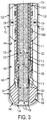
- FIG. 3 another enlarged cross-sectional view of the portion of the coring tool 100 of FIG. 1 is shown after procuring a core sample 140.
- the coring tool 100 may be introduced into a borehole 142 and positioned at a bottom of the borehole 142. Axial and rotational force may be applied to a drill string 144 of which the coring tool 100 is a part, and the coring bit 102 may rotate and be driven into the underlying earth formation 146.
- the cutting structure 106 may cut and remove earth material surrounding a central, columnar core sample 140, which may be received into the central bore 122 of the inner barrel 118 as the coring tool 100 advances.
- the stabilizer 124, and the other stabilizer 130 may remain rotationally stationary as the coring bit 102 rotates.
- Blades 132 of the stabilizer 124 may remain in contact with a wall 148 of the borehole 142.
- the blades 132 may remain rotationally stationary and may slide longitudinally along the wall 148 of the borehole 142 as the coring tool 100 advances axially to cut the core sample 140 from the underlying earth formation 146.
- the blades 132 of the stabilizer 124 may remain in contact with the wall 148 of the borehole 142.
- the blades 132 may extend radially outward to contact, and may press against, the wall 148 of the borehole 142.
- the stabilizer 124 may counteract forces urging the coring bit 102 to wander, reducing eccentricity of rotation of the coring bit 102.
- the exterior surface of the resulting core sample 140 may be located closer to the sponge material 128 lining the inner surface 120 of the inner barrel 118.
- a diameter D 4 of the core sample 140 may be closer to the diameter D 5 of the central bore 122. More specifically, the diameter D 4 of the core sample 140 may about 0.08 inch ( ⁇ 2.0 mm) (e.g., of a radius about 0.04 inch ( ⁇ 1.0 mm)) smaller than the diameter D 5 of the central bore 122.
- Reducing the size of a gap between the core sample 140 and the sponge material 128 may enable the sponge material 128 to capture a greater proportion of fluid escaping from the core sample 140 and to capture that fluid proximate the longitudinal location along the length of the core sample 140 from which the fluid escaped, causing the core sample 140 and the fluid captured from the core sample 140 to more accurately reflect the local and total characteristics of the downhole earth formation 146.
Landscapes
- Engineering & Computer Science (AREA)
- Geology (AREA)
- Life Sciences & Earth Sciences (AREA)
- Mining & Mineral Resources (AREA)
- Environmental & Geological Engineering (AREA)
- Fluid Mechanics (AREA)
- Physics & Mathematics (AREA)
- General Life Sciences & Earth Sciences (AREA)
- Geochemistry & Mineralogy (AREA)
- Mechanical Engineering (AREA)
- Sampling And Sample Adjustment (AREA)
- Investigation Of Foundation Soil And Reinforcement Of Foundation Soil By Compacting Or Drainage (AREA)
- Earth Drilling (AREA)
Description
- This application claims the benefit of the filing date of United States Patent Application Serial No.
14/328,318, filed July 10, 2014 U.S. Provisional Patent Application No. 61/847,944, filed July 18, 2013 - This disclosure relates generally to coring tools for procuring core samples of earth formations. More specifically, disclosed embodiments relate to coring tools including stabilizers that may increase the accuracy with which core samples procured using the coring tools reflect the actual characteristics of the earth formations from which the core sample were cut and reduce the likelihood that the core samples will become prematurely lodged within the coring tools.
- When evaluating whether a given earth formation contains valuable materials, such as fluid hydrocarbons, a core sample of the earth formation may be procured. For example, a coring tool, which may include a coring bit configured to remove earth material around a columnar core sample, may be placed at the bottom of a borehole and rotated under load to form a core sample. As the coring tool advances, the core sample may be received into an inner barrel within the coring tool, which may be configured to contain the core sample during retrieval and reduce (e.g., minimize) contamination until the core sample can be analyzed. When the core sample is returned to the surface, the core sample, any fluids entrapped within the core sample, and any fluids that escaped the core sample but were captured by the coring tool may be analyzed to determine the characteristics exhibited by the earth formation.
- To ensure that the core sample more accurately represents the actual characteristics of an earth formation at the end of a borehole, steps are taken to reduce the likelihood that contaminants enter the inner barrel that is to receive the core sample. For example, an entrance to the inner barrel may be sealed shut while advancing the coring tool into the borehole to reduce the likelihood that materials other than the core sample (e.g., drilling fluid and particles suspended within the drilling fluid) enter the inner barrel and contaminate the core sample. The entrance to the inner barrel may be sealed shut by, for example, an activation module that is intended to block the entrance to the inner barrel while the coring tool is advanced into the borehole and to unblock the entrance to the inner barrel when a core sample is introduced into the inner barrel. As a further example, the inner barrel may be substantially emptied of material and then filled, and potentially pressurized, with a presaturation fluid (i.e., a fluid of known composition that will not contaminate the core sample) before the coring tool is introduced into the borehole. The presaturation fluid may be selected such that a sponge material lining the interior of the inner barrel is not wettable by the presaturation fluid. The sponge material, however, may be a material that is wettable by a fluid of interest expected to be found within the core sample, such as oil or other hydrocarbons.
-
- In some embodiments, coring tools configured to procure core samples of earth formations may include a coring bit comprising a cutting structure configured to cut a core sample and an outer barrel connected to the coring bit. The outer barrel may be configured to apply axial and rotational force to the coring bit. An inner barrel may be located within the outer barrel and may be configured to receive a core sample within the inner barrel. A sponge material may line an inner surface of the inner barrel and may be configured to absorb a fluid from the core sample. A stabilizer may be connected to the outer barrel. At least one blade of the stabilizer may be rotatable with respect to the outer barrel and may be configured to remain at least substantially rotationally stationary relative to the earth formation during coring.
- In other embodiments, methods of procuring core samples of earth formations utilizing coring tools may involve positioning a coring bit connected to an outer barrel within a borehole. The coring bit may include a cutting structure configured to cut a core sample, and the outer barrel may be configured to apply axial and rotational force to the coring bit. The outer barrel and coring bit may be rotated under load to advance the coring bit into an underlying earth formation and form a core sample. At least a portion of the core sample may be received within an inner barrel located within the outer barrel as the inner barrel remains at least substantially rotationally stationary relative to the earth formation. The inner barrel may include a sponge material lining an inner surface of the inner barrel, the sponge material being configured to absorb a fluid from the core sample. The coring tool may be stabilized utilizing a stabilizer connected to the outer barrel as at least one blade of the stabilizer remains at least substantially rotationally stationary relative to the earth formation during coring.
- While this disclosure concludes with claims particularly pointing out and distinctly claiming specific embodiments, various features and advantages of embodiments within the scope of this disclosure may be more readily ascertained from the following description when read in conjunction with the accompanying drawings, in which:
-
FIG. 1 is a cross-sectional side view of a coring tool for procuring a core sample of an earth formation; -
FIG. 2 is an enlarged cross-sectional side view of a portion of the coring tool ofFIG. 1 ; and -
FIG. 3 is another enlarged cross-sectional view of the portion of the coring tool ofFIG. 1 after procuring a core sample. - The illustrations presented in this disclosure are not meant to be actual views of any particular stabilizer, coring tool, or component thereof, but are merely idealized representations employed to describe illustrative embodiments. Thus, the drawings are not necessarily to scale.
- Disclosed embodiments relate generally to coring tools including stabilizers that may increase the accuracy with which a core sample procured using the coring tools reflects the actual characteristics of the earth formation from which the core sample was cut, and that may reduce the likelihood that the core sample will become prematurely lodged within the coring tool. More specifically, disclosed are embodiments of stabilizers for coring tools that may reduce rotational eccentricity of coring bits or tools, resulting in core samples being cut more smoothly and closer to their intended diameter.
- Referring to
FIG. 1 , a cross-sectional side view of acoring tool 100 for procuring a core sample of an earth formation is shown. Thecoring tool 100 may include acoring bit 102 at a lowestlongitudinal end 104 of thecoring tool 100. Thecoring bit 102 may include acutting structure 106 configured to cut a core sample from an earth formation. Thecutting structure 106 may be, for example, a set of radially and longitudinally extending blades projecting from a remainder of thecoring bit 102 with cutting elements secured to the blades or a matrix material impregnated with abrasive cutting particles. Thecutting structure 106 may include aninner gage 108 surrounding acentral cavity 110 within thecoring bit 102. Thecutting structure 106 may be configured to cut around a periphery of a core sample, and thecentral cavity 110 may be configured to receive the core sample as thecoring bit 102 is advanced into the earth formation. Thecutting structure 106 may further include anouter gage 112 defining a radially outermost portion of thecoring bit 102. Theouter gage 112 may be configured to cut a sidewall of a wellbore being drilled by the coring tool 100as a core sample is taken. - The
coring tool 100 may further include anouter barrel 114 connected to thecoring bit 102. Theouter barrel 114 may be configured to apply axial and rotational force to the coring bit when forming a core sample. For example, theouter barrel 114 may be attached to a drill string proximate a lowest longitudinal end of the drill string, and axial and rotational force may be applied to the drill string and transmitted to thecoring bit 102. Theouter barrel 114 may be, for example, a tubular member extending longitudinally above thecoring bit 102. Theouter barrel 114 may be physically secured to thecoring bit 102 by, for example, ashank 116 interposed between and attached to theouter barrel 114 and thecoring bit 102. - An
inner barrel 118 may be located within theouter barrel 114. Theinner barrel 118 may be configured to receive a core sample within theinner barrel 118 for storage and preservation as thecoring tool 100 is retrieved from a wellbore. Theinner barrel 118 may be, for example, a tubular member connected to theouter barrel 114 in a manner allowing theinner barrel 118 to remain rotationally stationary while theouter barrel 114 rotates around theinner barrel 118. Aninner surface 120 of theinner barrel 118 may surround acentral bore 122 into which a core sample may be received as thecoring tool 100 is advanced into an earth formation. - A
sponge material 128 may line theinner surface 120 of theinner barrel 118. Thesponge material 128 may be configured of a material selected to absorb a fluid expected to be found within the core sample, such as, for example, hydrocarbons (e.g., oil). Thesponge material 128 may be, for example, a porous body characterized by an open network of pores into which fluid may infiltrate. Thesponge material 128 may be, for example, a foam (e.g., a polyurethane foam), felt, or any other material into which fluids may infiltrate (e.g., using capillary action to draw the fluid into the material), which may be preferentially wetted by hydrocarbons, such as oil. In embodiments where thesponge material 128 exhibits preferential wettability to hydrocarbons such as oil, the sampling of fluids within thesponge material 128 after procuring a core sample may more accurately reflect the concentration of a particular fluid of interest. Thesponge material 128 may be provided, for example, in sections that are individually inserted into theinner barrel 118 and attached to theinner barrel 118 adjacent to one another until they line an entire longitudinal length of theinner barrel 118 above a selected point. - In accordance with embodiments of the present disclosure, the
coring tool 100 may include astabilizer 124 located within a longitudinal extent of thecoring tool 100. For example, thestabilizer 124 may be located within a bottom half of a longitudinal extent of thecoring tool 100. More specifically, thestabilizer 124 may be located within a bottom third of the longitudinal extent of thecoring tool 100. As another example, thestabilizer 124 may be located within an upper half of the longitudinal extent of thecoring tool 100. - The
stabilizer 124 may be rotatably connected to theouter barrel 114. In other words, thestabilizer 124 may be connected to theouter barrel 114 in a manner that enables thestabilizer 124 to remain at least substantially, rotationally stationary while theouter barrel 114 andcoring bit 102 rotate during a coring process. Thestabilizer 124 may be configured to reduce eccentric rotation of thecoring bit 102. When thecoring bit 102 is rotated within a wellbore, thecoring bit 102 may tend to rotate about an axis of rotation that is offset from alongitudinal axis 126 extending along a radial centerline of thecoring tool 100. For example, imbalanced cutting forces acting on the cuttingstructure 106, earth formations of varying compositions being impacted by different portions of the cuttingstructure 106, and misaligned axial forces acting on thecoring bit 102 may cause thecoring bit 102 to rotate unintentionally about an axis of rotation that is offset from thelongitudinal axis 126 of thecoring tool 100. Eccentric rotation of thecoring bit 102 may cause theinner gage 108 of the cuttingstructure 106 to cut a core sample that is significantly smaller in diameter than desired, leaving a larger-than-intended annular space between a periphery of the core sample and thesponge material 128 lining theinner surface 120 of theinner barrel 118. Fluids escaping from the core sample may travel axially along the annular space, eventually being captured by thesponge material 128 at a different longitudinal position or escaping the inner barrel to circulate with drilling fluid pumped downhole to lubricate, cool, and remove cuttings from thecoring tool 100. In other words, eccentric rotation of thecoring bit 102 may result less accurate representation of both local and total earth formation characteristics. Thestabilizer 124 may be configured to reduce eccentric rotation of thecoring bit 102. For example, thestabilizer 124 may press against the wall of a borehole to counteract the tendency of thecoring bit 102 to rotate eccentrically. In addition, the stabilizer may reduce lateral vibrations and other lateral movements (i.e., vibrations and movements in a direction at least substantially perpendicular to the longitudinal axis 126), which may enable use of asponge 128 exhibiting a small inner diameter to increase efficiency and accuracy of fluid capture by thesponge 128. - In some embodiments, another
stabilizer 130 may be connected to the drill string to which thecoring bit 102 is connected, theother stabilizer 130 being located longitudinally farther from thecoring bit 102 than thestabilizer 124. For example, theother stabilizer 130 may be located above a longitudinal upper extent of thecoring tool 100. Theother stabilizer 130 may be configured to further reduce eccentric rotation of thecoring bit 102, lateral vibration of thecoring bit 102, and other lateral movement of thecoring bit 102. Theother stabilizer 130 may be configured in a manner at least substantially similar to thestabilizer 124, with differences between thestabilizers - Referring to
FIG. 2 , an enlarged cross-sectional side view of a portion of thecoring tool 100 ofFIG. 1 is shown. Thestabilizer 124 may include longitudinally and radially extendingblades 132 configured to contact and ride on a wall of a borehole. Theblades 132 of thestabilizer 124 may extend longitudinally at least substantially parallel (i.e., parallel within manufacturing tolerances) to thelongitudinal axis 126 of thecoring tool 100, which may enable detritus suspended within drilling fluid to more easily flow past theblades 132 and reduce adhesion, accumulation, and balling of formation cuttings on theblades 132. More specifically, acentral axis 134 geometrically equidistant from the lateral ends of eachblade 132 may be at least substantially parallel to thelongitudinal axis 126 of thecoring tool 100. Orienting theblades 132 at least substantially parallel to thelongitudinal axis 126 of thecoring tool 100 may further reduce the likelihood that thestabilizer 124 will contact and become lodged against borehole outcroppings when travelling axially along the borehole because the periphery of theblades 132 does not extend around an entire circumference of thestabilizer 124, leaving gaps through which such outcroppings may pass. - An outer diameter D1 of the
stabilizer 124 may be, for example, at least substantially equal to an outer diameter D2 of thecoring bit 102 at theouter gage 112, which may enable thestabilizer 124 to better reduce eccentric rotation of thecoring bit 102. The outer diameter D1 of thestabilizer 124 may be equal to the outer diameter D2 of thecoring bit 102 at theouter gage 112 in some embodiments. In other embodiments, the outer diameter D1 of thestabilizer 124 may be less than the outer diameter D2 of thecoring bit 102 at theouter gage 112. For example, the outer diameter D1 of thestabilizer 124 may be between about 98% and about 100% of the outer diameter D2 of thecoring bit 102 at theouter gage 112. More specifically, the outer diameter D1 of thestabilizer 124 may be, for example, between about 99% and about 100% (e.g., about 100%) of the outer diameter D2 of thecoring bit 102 at theouter gage 112. As another example, the outer diameter D1 of thestabilizer 124 may within about 0.125 inch (∼3.2 mm) of the outer diameter D2 of thecoring bit 102 at theouter gage 112. More specifically, the outer diameter D1 of thestabilizer 124 may be, for example, about 0.04 inch (∼1.0 mm) or less (e.g., about 0.02 inch (∼0.5 mm)) smaller than the outer diameter D2 of thecoring bit 102 at theouter gage 112. As yet another example, the outer diameter D1 of thestabilizer 124 may between about 8.46 inches (∼21.49 cm) and about 8.5 inches (∼21.59 cm). More specifically, the outer diameter D1 of thestabilizer 124 may be, for example, between about 8.48 inches (∼21.53 cm) and about 8.5 inches (∼21.59 cm) (e.g., about 8.49 inches (∼21.56 cm)). - The
stabilizer 124 may include bearings 136 configured to transmit radial and axial loads between thestabilizer 124 and theouter barrel 114 while enabling the stabilizer to remain at least substantially rotationally stationary while theouter barrel 114 rotates. For example, thestabilizer 124 may includeradial bearings 136A (e.g., concentric annular members including rubbing bearing surfaces or ball bearings) extending around a circumference of theouter barrel 114 andaxial bearings 136B (e.g., longitudinally stacked annular members including rubbing bearing surfaces or ball or roller bearings) at upper and lower ends of thestabilizer 124. - In some embodiments, the
blades 134 of thestabilizer 124 may be extensible to maintain contact against a wall of a borehole, and may even actively press against the wall of the borehole. For example, theblades 134 may include anextension mechanism 138 enabling theblades 134 to extend and retract radially to maintain contact against a wall of a borehole. Theextension mechanism 138 may be, for example, a spring-loaded bias or an electronically controlled hydraulic or mechanical drive system configured to extend theblades 134 radially outward to maintain contact against the wall of a borehole. - In some embodiments, the
stabilizer 124 may be located proximate the lowestlongitudinal end 104 of thecoring tool 100, while remaining longitudinally above thecoring bit 102, which proximity may enable thestabilizer 124 to better reduce eccentric rotation of thecoring bit 102. When it is said that thestabilizer 124 may be located "proximate" the lowestlongitudinal end 102 of thecoring tool 100, what is meant is that thestabilizer 124 is the next direct component in the drill string connected to the coring bit 102 (e.g., on the outer barrel 114), or the next component in the drill string after ashank 116 between thestabilizer 124 and thecoring bit 102. For example, thestabilizer 124 may be located about 5 feet (∼1.5 m) or less from the lowestlongitudinal end 104 of thecoring tool 100. More specifically, the stabilizer may be located about 2 feet (∼0.6 m) or less (e.g., about 1 foot (∼0.3 m) or less) from the lowestlongitudinal end 104 of thecoring tool 100. - Returning to
FIG. 1 , theother stabilizer 130 may be of at least substantially the same design and dimensions as thestabilizer 124 in some embodiments. For example, an outer diameter D3 of theother stabilizer 130 may be at least substantially equal to the outer diameter D2 of thecoring bit 102 at theouter gage 112. More specifically, the outer diameter D3 of theother stabilizer 130 may be equal to the outer diameter D1 of thestabilizer 124. In other embodiments, theother stabilizer 130 may be different from thestabilizer 124. For example, the outer diameter D3 of theother stabilizer 130 may be less than the outer diameter D2 of thecoring bit 102 at theouter gage 112. More specifically, the outer diameter D3 of theother stabilizer 130 may be less than the outer diameter D1 of thestabilizer 124. As a specific, nonlimiting example, the outer diameter D3 of theother stabilizer 130 may be between about 0.1 inch (∼2.5 mm) and about 1.0 inch (∼25.4 mm) (e.g., about 0.5 inch (∼12.7 mm)) less than the outer diameter D1 of thestabilizer 124. - A distance d between the
stabilizer 124 and theother stabilizer 130 may be about 50 feet (∼15.2 m) or less. For example, the longitudinal distance d between thestabilizer 124 and theother stabilizer 130 may be about 30 feet (∼9.1 m) or less. More specifically, the longitudinal distance d between thestabilizer 124 and theother stabilizer 130 may be between about 10 feet (∼3.0 m) and about 20 feet (∼6.1 m) (e.g., about 15 feet (∼4.6 m)). A distance between thestabilizer 124 and an upper extent of thecoring tool 124 may be, for example, less than 30 feet (∼9.1 m). More specifically, the distance between thestabilizer 124 and the upper extent of thecoring tool 100 may be less than 10 feet (∼3.0 m). As a specific, nonlimiting example, the distance between thestabilizer 124 and the upper extent of thecoring tool 100 may be less than 5 feet (∼1.5 m). - In some embodiments, the
other stabilizer 130 may be rotatable with respect to thecoring bit 102 such that theother stabilizer 130 may remain rotationally stationary while thecoring bit 102 rotates. In other embodiments, theother stabilizer 130 may not be rotatable with respect to thecoring bit 102 such that rotation of the drill string to rotatecoring bit 102 results in corresponding synchronous rotation of theother stabilizer 130. - Referring to
FIG. 3 , another enlarged cross-sectional view of the portion of thecoring tool 100 ofFIG. 1 is shown after procuring a core sample 140. Thecoring tool 100 may be introduced into aborehole 142 and positioned at a bottom of theborehole 142. Axial and rotational force may be applied to adrill string 144 of which thecoring tool 100 is a part, and thecoring bit 102 may rotate and be driven into theunderlying earth formation 146. The cuttingstructure 106 may cut and remove earth material surrounding a central, columnar core sample 140, which may be received into thecentral bore 122 of theinner barrel 118 as thecoring tool 100 advances. - The
stabilizer 124, and the other stabilizer 130 (seeFIG. 1 ) in some embodiments, may remain rotationally stationary as thecoring bit 102 rotates.Blades 132 of thestabilizer 124 may remain in contact with awall 148 of theborehole 142. Theblades 132 may remain rotationally stationary and may slide longitudinally along thewall 148 of the borehole 142 as thecoring tool 100 advances axially to cut the core sample 140 from theunderlying earth formation 146. Theblades 132 of thestabilizer 124 may remain in contact with thewall 148 of theborehole 142. For example, in embodiments where thestabilizer 124 includes anextension mechanism 138, theblades 132 may extend radially outward to contact, and may press against, thewall 148 of theborehole 142. As thecoring bit 102 is urged to wander, tending to misalign the axis of rotation of thecoring bit 102 from thelongitudinal axis 126 of thecoring tool 100, thestabilizer 124 may counteract forces urging thecoring bit 102 to wander, reducing eccentricity of rotation of thecoring bit 102. - The exterior surface of the resulting core sample 140 may be located closer to the
sponge material 128 lining theinner surface 120 of theinner barrel 118. For example, a diameter D4 of the core sample 140 may be closer to the diameter D5 of thecentral bore 122. More specifically, the diameter D4 of the core sample 140 may about 0.08 inch (∼2.0 mm) (e.g., of a radius about 0.04 inch (∼1.0 mm)) smaller than the diameter D5 of thecentral bore 122. Reducing the size of a gap between the core sample 140 and thesponge material 128 may enable thesponge material 128 to capture a greater proportion of fluid escaping from the core sample 140 and to capture that fluid proximate the longitudinal location along the length of the core sample 140 from which the fluid escaped, causing the core sample 140 and the fluid captured from the core sample 140 to more accurately reflect the local and total characteristics of thedownhole earth formation 146.
Claims (15)
- A coring tool (100) configured to procure a core sample (140) of an earth formation (146), comprising:a coring bit (102) comprising a cutting structure (106) configured to cut a core sample (140);an outer barrel (114) connected to the coring bit (102), the outer barrel (114) configured to apply axial and rotational force to the coring bit (102);an inner barrel (118) located within the outer barrel (114), the inner barrel (118) being configured to receive the core sample (140) within the inner barrel (118); anda sponge material (128) lining an inner surface (120) of the inner barrel (118), the sponge material (128) being configured to absorb a fluid from the core sample (140);the coring tool (100) characterized in that the coring tool (100) further comprises a stabilizer (124) connected to the outer barrel (114), at least one blade (132) of the stabilizer (124) being rotatable with respect to the outer barrel (114) and configured to remain at least substantially rotationally stationary relative to the earth formation (146) during coring.
- The coring tool (100) of claim 1, wherein the stabilizer (124) is located within a longitudinal extent of the coring tool (100).
- The coring tool (100) of claim 2, wherein the stabilizer (124) is located in a lower half of the coring tool (100).
- The coring tool (100) of claim 1, wherein the stabilizer (124) located above a longitudinal extent of the coring tool (100).
- The coring tool (100) of claim 1, wherein a distance between the stabilizer (124) and an upper extent of the coring tool (100) is less than 30 feet (∼9.1 m).
- The coring tool (100) of claim 1, further comprising another stabilizer (130) connected to the outer barrel (114), wherein a distance (d) between the stabilizer (124) and the other stabilizer (130) is about 50 feet (∼15.2 m) or less.
- The coring tool (100) of any one of claims 1 through 6, wherein an outer diameter (D1) of the stabilizer (124) is about 0.125 inch (∼3.2 mm) or less smaller than an outer diameter (D2) of the coring bit (102) at an outer gage (112) of the cutting structure (106).
- The coring tool (100) of any one of claims 1 through 6, wherein the at least one blade (132) of the stabilizer (124) extends at least substantially parallel to a longitudinal axis (126) of the coring tool (100).
- The coring tool (100) of any one of claims 1 through 6, wherein the at least one blade (132) of the stabilizer (124) is extensible to reduce the distance between the surface of the at least one blade (132) and a wall of a borehole (142).
- A method of procuring a core sample (140) of an earth formation (146) utilizing a coring tool (100), comprising:positioning a coring bit (102) connected to an outer barrel (114) within a borehole (142), the coring bit (102) comprising a cutting structure (106) configured to cut a core sample (140), the outer barrel (114) configured to apply axial and rotational force to the coring bit (102);rotating the outer barrel (114) and coring bit (102) under load to advance the coring bit (102) into an underlying earth formation (146) and form the core sample (140); andreceiving at least a portion of the core sample (140) within an inner barrel (118) located within the outer barrel (114) as the inner barrel (118) remains at least substantially rotationally stationary relative to the earth formation (146), the inner barrel (118) including a sponge material (128) lining an inner surface (120) of the inner barrel (118), the sponge material (128) being configured to absorb a fluid from the core sample (140);the method characterized in that the method further comprises stabilizing the coring tool (100) utilizing a stabilizer (124) connected to the outer barrel (114) as at least one blade (132) of the stabilizer (124) remains at least substantially rotationally stationary relative to the earth formation (146) during coring.
- The method of claim 10, further comprising flowing drilling fluid between blades (132) of the stabilizer (124), the blades (132) extending at least substantially parallel to a longitudinal axis (126) of the coring tool (100).
- The method of claim 10, further comprising selectively, radially extending the at least one blade (132) of the stabilizer (124) to reduce a distance between the at least one blade (132) and a wall of the borehole (142).
- The method of any one of claims 10 through 12, wherein stabilizing the coring tool (100) utilizing the stabilizer (124) comprises stabilizing the coring tool (100) utilizing the stabilizer (124), an outer diameter (D1) of the stabilizer (124) being about 0.125 inch (∼3.2 mm) or less smaller than an outer diameter (D2) of the coring bit (102) at an outer gage (112) of the cutting structure (106).
- The method of any one of claims 10 through 12, wherein stabilizing the coring tool (100) utilizing the stabilizer (124) comprises stabilizing the coring tool (100) utilizing the stabilizer (124) located within a longitudinal extent of the coring tool (100).
- The method of any one of claims 10 through 12, wherein stabilizing the coring tool (100) utilizing the stabilizer (124) comprises stabilizing the coring tool (100) utilizing the stabilizer (124) located above a longitudinal extent of the coring tool (100).
Applications Claiming Priority (2)
| Application Number | Priority Date | Filing Date | Title |
|---|---|---|---|
| US14/328,318 US9567813B2 (en) | 2013-07-18 | 2014-07-10 | Coring tools exhibiting reduced rotational eccentricity and related methods |
| PCT/US2015/039916 WO2016007840A1 (en) | 2014-07-10 | 2015-07-10 | Coring tools exhibiting reduced rotational eccentricity and related methods |
Publications (3)
| Publication Number | Publication Date |
|---|---|
| EP3167144A1 EP3167144A1 (en) | 2017-05-17 |
| EP3167144A4 EP3167144A4 (en) | 2018-03-21 |
| EP3167144B1 true EP3167144B1 (en) | 2020-01-15 |
Family
ID=55064952
Family Applications (1)
| Application Number | Title | Priority Date | Filing Date |
|---|---|---|---|
| EP15819474.6A Active EP3167144B1 (en) | 2014-07-10 | 2015-07-10 | Coring tools exhibiting reduced rotational eccentricity and related methods |
Country Status (3)
| Country | Link |
|---|---|
| US (2) | US9567813B2 (en) |
| EP (1) | EP3167144B1 (en) |
| WO (1) | WO2016007840A1 (en) |
Families Citing this family (13)
| Publication number | Priority date | Publication date | Assignee | Title |
|---|---|---|---|---|
| DE102013213232B4 (en) * | 2013-07-05 | 2022-07-07 | Olympus Winter & Ibe Gmbh | Side view endoscope |
| US9567813B2 (en) * | 2013-07-18 | 2017-02-14 | Baker Hughes Incorporated | Coring tools exhibiting reduced rotational eccentricity and related methods |
| US9765585B2 (en) * | 2013-07-18 | 2017-09-19 | Baker Hughes Incorporated | Coring tools and methods for making coring tools and procuring core samples |
| CN106289858B (en) * | 2016-07-22 | 2018-09-11 | 中国地质大学(武汉) | Collet formula undisturbed soil soil sampler |
| US10975644B2 (en) | 2016-12-06 | 2021-04-13 | Halliburton Energy Services, Inc. | Inner barrel assembly for recovery of reservoir fluids from a core sample |
| CN109655307B (en) * | 2019-01-30 | 2023-10-27 | 中国地质大学(武汉) | An undisturbed soil sampler |
| US11131147B1 (en) * | 2020-04-29 | 2021-09-28 | Coreall As | Core drilling apparatus and method for converting between a core drilling assembly and a full-diameter drilling assembly |
| CN112229671B (en) * | 2020-09-24 | 2021-09-21 | 锡林郭勒盟山金白音呼布矿业有限公司 | Equidistance face formula rock dust sampling tool |
| CN112252971B (en) * | 2020-09-30 | 2022-01-25 | 中国地质大学(武汉) | Spline type horizontal directional drilling engineering geological exploration steering control device |
| CN112252972B (en) * | 2020-09-30 | 2022-01-25 | 中国地质大学(武汉) | Eccentric ring type horizontal directional core drilling tool and direction control device thereof |
| CN113982515B (en) * | 2021-10-28 | 2022-07-15 | 中国地质大学(北京) | Pressure maintaining coring device |
| CN114215479B (en) * | 2021-11-24 | 2023-09-19 | 北京卫星制造厂有限公司 | Drilling tool |
| CN118582179B (en) * | 2024-08-06 | 2024-10-29 | 中国电建集团成都勘测设计研究院有限公司 | Flexible guide core drill |
Family Cites Families (15)
| Publication number | Priority date | Publication date | Assignee | Title |
|---|---|---|---|---|
| US4598777A (en) * | 1983-07-13 | 1986-07-08 | Diamond Oil Well Drilling Company | Method and apparatus for preventing contamination of a coring sponge |
| US4502553A (en) * | 1983-07-13 | 1985-03-05 | Diamond Oil Well Drilling | Sponge coring apparatus with reinforced sponge |
| US4638872A (en) * | 1985-04-01 | 1987-01-27 | Diamond Oil Well Drilling Company | Core monitoring device |
| US4606417A (en) | 1985-04-08 | 1986-08-19 | Webb Derrel D | Pressure equalized stabilizer apparatus for drill string |
| US5235285A (en) * | 1991-10-31 | 1993-08-10 | Schlumberger Technology Corporation | Well logging apparatus having toroidal induction antenna for measuring, while drilling, resistivity of earth formations |
| US5560439A (en) | 1995-04-17 | 1996-10-01 | Delwiche; Robert A. | Method and apparatus for reducing the vibration and whirling of drill bits and the bottom hole assembly in drilling used to drill oil and gas wells |
| IN188195B (en) | 1995-05-19 | 2002-08-31 | Validus Internat Company L L C | |
| BE1009968A5 (en) | 1996-01-15 | 1997-11-04 | Dresser Ind | Core core and method for its implementation. |
| US6009960A (en) * | 1998-01-27 | 2000-01-04 | Diamond Products International, Inc. | Coring tool |
| US6216804B1 (en) | 1998-07-29 | 2001-04-17 | James T. Aumann | Apparatus for recovering core samples under pressure |
| US6719070B1 (en) * | 2000-11-14 | 2004-04-13 | Baker Hughes Incorporated | Apparatus and methods for sponge coring |
| US7256582B2 (en) * | 2005-04-20 | 2007-08-14 | Baker Hughes Incorporated | Method and apparatus for improved current focusing in galvanic resistivity measurement tools for wireline and measurement-while-drilling applications |
| US8162080B2 (en) * | 2007-09-25 | 2012-04-24 | Baker Hughes Incorporated | Apparatus and methods for continuous coring |
| US20140166366A1 (en) | 2012-12-13 | 2014-06-19 | Smith International, Inc. | Single-trip lateral coring systems and methods |
| US9567813B2 (en) * | 2013-07-18 | 2017-02-14 | Baker Hughes Incorporated | Coring tools exhibiting reduced rotational eccentricity and related methods |
-
2014
- 2014-07-10 US US14/328,318 patent/US9567813B2/en active Active
-
2015
- 2015-07-10 WO PCT/US2015/039916 patent/WO2016007840A1/en not_active Ceased
- 2015-07-10 EP EP15819474.6A patent/EP3167144B1/en active Active
-
2017
- 2017-02-13 US US15/430,673 patent/US20170152714A1/en not_active Abandoned
Non-Patent Citations (1)
| Title |
|---|
| None * |
Also Published As
| Publication number | Publication date |
|---|---|
| US20170152714A1 (en) | 2017-06-01 |
| WO2016007840A1 (en) | 2016-01-14 |
| EP3167144A1 (en) | 2017-05-17 |
| US9567813B2 (en) | 2017-02-14 |
| EP3167144A4 (en) | 2018-03-21 |
| US20160010401A1 (en) | 2016-01-14 |
Similar Documents
| Publication | Publication Date | Title |
|---|---|---|
| EP3167144B1 (en) | Coring tools exhibiting reduced rotational eccentricity and related methods | |
| US9765585B2 (en) | Coring tools and methods for making coring tools and procuring core samples | |
| US8210284B2 (en) | Coring apparatus and methods to use the same | |
| US10494876B2 (en) | Earth-boring tools including rotatable bearing elements and related methods | |
| RU2713542C2 (en) | Drilling bit with extending calibrating platforms | |
| US9097102B2 (en) | Downhole coring tools and methods of coring | |
| WO2007084623A3 (en) | Hole coring system | |
| AU2012100921A4 (en) | Thrust bearing assembly for a wireline-operated directional core barrel drill | |
| US11708726B2 (en) | Horizontal directional reaming | |
| US9702196B2 (en) | Coring tool including core bit and drilling plug with alignment and torque transmission apparatus and related methods | |
| US11248419B2 (en) | Hybrid drill bit | |
| US10975683B2 (en) | Coring tools enabling measurement of dynamic responses of inner barrels and related methods | |
| AU2011101137A4 (en) | Thrust bearing assembly for a wireline-operated directional core barrel drill | |
| US9611846B2 (en) | Flow restrictor for a mud motor | |
| US20140182937A1 (en) | Roller cone drill bit | |
| US11319756B2 (en) | Hybrid reamer and stabilizer | |
| US20240003209A1 (en) | Core barrel and core drilling systems and methods |
Legal Events
| Date | Code | Title | Description |
|---|---|---|---|
| STAA | Information on the status of an ep patent application or granted ep patent |
Free format text: STATUS: THE INTERNATIONAL PUBLICATION HAS BEEN MADE |
|
| PUAI | Public reference made under article 153(3) epc to a published international application that has entered the european phase |
Free format text: ORIGINAL CODE: 0009012 |
|
| STAA | Information on the status of an ep patent application or granted ep patent |
Free format text: STATUS: REQUEST FOR EXAMINATION WAS MADE |
|
| 17P | Request for examination filed |
Effective date: 20170126 |
|
| AK | Designated contracting states |
Kind code of ref document: A1 Designated state(s): AL AT BE BG CH CY CZ DE DK EE ES FI FR GB GR HR HU IE IS IT LI LT LU LV MC MK MT NL NO PL PT RO RS SE SI SK SM TR |
|
| AX | Request for extension of the european patent |
Extension state: BA ME |
|
| DAV | Request for validation of the european patent (deleted) | ||
| DAX | Request for extension of the european patent (deleted) | ||
| A4 | Supplementary search report drawn up and despatched |
Effective date: 20180221 |
|
| RIC1 | Information provided on ipc code assigned before grant |
Ipc: E21B 49/02 20060101ALI20180215BHEP Ipc: E21B 25/00 20060101ALI20180215BHEP Ipc: E21B 10/02 20060101AFI20180215BHEP Ipc: G01N 1/08 20060101ALI20180215BHEP |
|
| GRAP | Despatch of communication of intention to grant a patent |
Free format text: ORIGINAL CODE: EPIDOSNIGR1 |
|
| STAA | Information on the status of an ep patent application or granted ep patent |
Free format text: STATUS: GRANT OF PATENT IS INTENDED |
|
| INTG | Intention to grant announced |
Effective date: 20190729 |
|
| GRAS | Grant fee paid |
Free format text: ORIGINAL CODE: EPIDOSNIGR3 |
|
| GRAA | (expected) grant |
Free format text: ORIGINAL CODE: 0009210 |
|
| STAA | Information on the status of an ep patent application or granted ep patent |
Free format text: STATUS: THE PATENT HAS BEEN GRANTED |
|
| RAP1 | Party data changed (applicant data changed or rights of an application transferred) |
Owner name: BAKER HUGHES, A GE COMPANY, LLC |
|
| AK | Designated contracting states |
Kind code of ref document: B1 Designated state(s): AL AT BE BG CH CY CZ DE DK EE ES FI FR GB GR HR HU IE IS IT LI LT LU LV MC MK MT NL NO PL PT RO RS SE SI SK SM TR |
|
| REG | Reference to a national code |
Ref country code: CH Ref legal event code: EP Ref country code: GB Ref legal event code: FG4D |
|
| REG | Reference to a national code |
Ref country code: IE Ref legal event code: FG4D |
|
| REG | Reference to a national code |
Ref country code: DE Ref legal event code: R096 Ref document number: 602015045735 Country of ref document: DE |
|
| REG | Reference to a national code |
Ref country code: AT Ref legal event code: REF Ref document number: 1225301 Country of ref document: AT Kind code of ref document: T Effective date: 20200215 |
|
| REG | Reference to a national code |
Ref country code: NL Ref legal event code: MP Effective date: 20200115 |
|
| REG | Reference to a national code |
Ref country code: NO Ref legal event code: T2 Effective date: 20200115 |
|
| REG | Reference to a national code |
Ref country code: LT Ref legal event code: MG4D |
|
| PG25 | Lapsed in a contracting state [announced via postgrant information from national office to epo] |
Ref country code: NL Free format text: LAPSE BECAUSE OF FAILURE TO SUBMIT A TRANSLATION OF THE DESCRIPTION OR TO PAY THE FEE WITHIN THE PRESCRIBED TIME-LIMIT Effective date: 20200115 Ref country code: FI Free format text: LAPSE BECAUSE OF FAILURE TO SUBMIT A TRANSLATION OF THE DESCRIPTION OR TO PAY THE FEE WITHIN THE PRESCRIBED TIME-LIMIT Effective date: 20200115 Ref country code: PT Free format text: LAPSE BECAUSE OF FAILURE TO SUBMIT A TRANSLATION OF THE DESCRIPTION OR TO PAY THE FEE WITHIN THE PRESCRIBED TIME-LIMIT Effective date: 20200607 Ref country code: RS Free format text: LAPSE BECAUSE OF FAILURE TO SUBMIT A TRANSLATION OF THE DESCRIPTION OR TO PAY THE FEE WITHIN THE PRESCRIBED TIME-LIMIT Effective date: 20200115 |
|
| PG25 | Lapsed in a contracting state [announced via postgrant information from national office to epo] |
Ref country code: GR Free format text: LAPSE BECAUSE OF FAILURE TO SUBMIT A TRANSLATION OF THE DESCRIPTION OR TO PAY THE FEE WITHIN THE PRESCRIBED TIME-LIMIT Effective date: 20200416 Ref country code: HR Free format text: LAPSE BECAUSE OF FAILURE TO SUBMIT A TRANSLATION OF THE DESCRIPTION OR TO PAY THE FEE WITHIN THE PRESCRIBED TIME-LIMIT Effective date: 20200115 Ref country code: SE Free format text: LAPSE BECAUSE OF FAILURE TO SUBMIT A TRANSLATION OF THE DESCRIPTION OR TO PAY THE FEE WITHIN THE PRESCRIBED TIME-LIMIT Effective date: 20200115 Ref country code: IS Free format text: LAPSE BECAUSE OF FAILURE TO SUBMIT A TRANSLATION OF THE DESCRIPTION OR TO PAY THE FEE WITHIN THE PRESCRIBED TIME-LIMIT Effective date: 20200515 Ref country code: BG Free format text: LAPSE BECAUSE OF FAILURE TO SUBMIT A TRANSLATION OF THE DESCRIPTION OR TO PAY THE FEE WITHIN THE PRESCRIBED TIME-LIMIT Effective date: 20200415 Ref country code: LV Free format text: LAPSE BECAUSE OF FAILURE TO SUBMIT A TRANSLATION OF THE DESCRIPTION OR TO PAY THE FEE WITHIN THE PRESCRIBED TIME-LIMIT Effective date: 20200115 |
|
| REG | Reference to a national code |
Ref country code: DE Ref legal event code: R097 Ref document number: 602015045735 Country of ref document: DE |
|
| PG25 | Lapsed in a contracting state [announced via postgrant information from national office to epo] |
Ref country code: SM Free format text: LAPSE BECAUSE OF FAILURE TO SUBMIT A TRANSLATION OF THE DESCRIPTION OR TO PAY THE FEE WITHIN THE PRESCRIBED TIME-LIMIT Effective date: 20200115 Ref country code: EE Free format text: LAPSE BECAUSE OF FAILURE TO SUBMIT A TRANSLATION OF THE DESCRIPTION OR TO PAY THE FEE WITHIN THE PRESCRIBED TIME-LIMIT Effective date: 20200115 Ref country code: DK Free format text: LAPSE BECAUSE OF FAILURE TO SUBMIT A TRANSLATION OF THE DESCRIPTION OR TO PAY THE FEE WITHIN THE PRESCRIBED TIME-LIMIT Effective date: 20200115 Ref country code: LT Free format text: LAPSE BECAUSE OF FAILURE TO SUBMIT A TRANSLATION OF THE DESCRIPTION OR TO PAY THE FEE WITHIN THE PRESCRIBED TIME-LIMIT Effective date: 20200115 Ref country code: RO Free format text: LAPSE BECAUSE OF FAILURE TO SUBMIT A TRANSLATION OF THE DESCRIPTION OR TO PAY THE FEE WITHIN THE PRESCRIBED TIME-LIMIT Effective date: 20200115 Ref country code: CZ Free format text: LAPSE BECAUSE OF FAILURE TO SUBMIT A TRANSLATION OF THE DESCRIPTION OR TO PAY THE FEE WITHIN THE PRESCRIBED TIME-LIMIT Effective date: 20200115 Ref country code: ES Free format text: LAPSE BECAUSE OF FAILURE TO SUBMIT A TRANSLATION OF THE DESCRIPTION OR TO PAY THE FEE WITHIN THE PRESCRIBED TIME-LIMIT Effective date: 20200115 Ref country code: SK Free format text: LAPSE BECAUSE OF FAILURE TO SUBMIT A TRANSLATION OF THE DESCRIPTION OR TO PAY THE FEE WITHIN THE PRESCRIBED TIME-LIMIT Effective date: 20200115 |
|
| REG | Reference to a national code |
Ref country code: AT Ref legal event code: MK05 Ref document number: 1225301 Country of ref document: AT Kind code of ref document: T Effective date: 20200115 |
|
| PLBE | No opposition filed within time limit |
Free format text: ORIGINAL CODE: 0009261 |
|
| STAA | Information on the status of an ep patent application or granted ep patent |
Free format text: STATUS: NO OPPOSITION FILED WITHIN TIME LIMIT |
|
| 26N | No opposition filed |
Effective date: 20201016 |
|
| PG25 | Lapsed in a contracting state [announced via postgrant information from national office to epo] |
Ref country code: IT Free format text: LAPSE BECAUSE OF FAILURE TO SUBMIT A TRANSLATION OF THE DESCRIPTION OR TO PAY THE FEE WITHIN THE PRESCRIBED TIME-LIMIT Effective date: 20200115 Ref country code: AT Free format text: LAPSE BECAUSE OF FAILURE TO SUBMIT A TRANSLATION OF THE DESCRIPTION OR TO PAY THE FEE WITHIN THE PRESCRIBED TIME-LIMIT Effective date: 20200115 |
|
| REG | Reference to a national code |
Ref country code: DE Ref legal event code: R119 Ref document number: 602015045735 Country of ref document: DE |
|
| PG25 | Lapsed in a contracting state [announced via postgrant information from national office to epo] |
Ref country code: SI Free format text: LAPSE BECAUSE OF FAILURE TO SUBMIT A TRANSLATION OF THE DESCRIPTION OR TO PAY THE FEE WITHIN THE PRESCRIBED TIME-LIMIT Effective date: 20200115 Ref country code: MC Free format text: LAPSE BECAUSE OF FAILURE TO SUBMIT A TRANSLATION OF THE DESCRIPTION OR TO PAY THE FEE WITHIN THE PRESCRIBED TIME-LIMIT Effective date: 20200115 Ref country code: PL Free format text: LAPSE BECAUSE OF FAILURE TO SUBMIT A TRANSLATION OF THE DESCRIPTION OR TO PAY THE FEE WITHIN THE PRESCRIBED TIME-LIMIT Effective date: 20200115 |
|
| REG | Reference to a national code |
Ref country code: CH Ref legal event code: PL |
|
| REG | Reference to a national code |
Ref country code: BE Ref legal event code: MM Effective date: 20200731 |
|
| PG25 | Lapsed in a contracting state [announced via postgrant information from national office to epo] |
Ref country code: CH Free format text: LAPSE BECAUSE OF NON-PAYMENT OF DUE FEES Effective date: 20200731 Ref country code: LU Free format text: LAPSE BECAUSE OF NON-PAYMENT OF DUE FEES Effective date: 20200710 Ref country code: LI Free format text: LAPSE BECAUSE OF NON-PAYMENT OF DUE FEES Effective date: 20200731 Ref country code: FR Free format text: LAPSE BECAUSE OF NON-PAYMENT OF DUE FEES Effective date: 20200731 |
|
| PG25 | Lapsed in a contracting state [announced via postgrant information from national office to epo] |
Ref country code: BE Free format text: LAPSE BECAUSE OF NON-PAYMENT OF DUE FEES Effective date: 20200731 Ref country code: DE Free format text: LAPSE BECAUSE OF NON-PAYMENT OF DUE FEES Effective date: 20210202 |
|
| PG25 | Lapsed in a contracting state [announced via postgrant information from national office to epo] |
Ref country code: IE Free format text: LAPSE BECAUSE OF NON-PAYMENT OF DUE FEES Effective date: 20200710 |
|
| PG25 | Lapsed in a contracting state [announced via postgrant information from national office to epo] |
Ref country code: TR Free format text: LAPSE BECAUSE OF FAILURE TO SUBMIT A TRANSLATION OF THE DESCRIPTION OR TO PAY THE FEE WITHIN THE PRESCRIBED TIME-LIMIT Effective date: 20200115 Ref country code: MT Free format text: LAPSE BECAUSE OF FAILURE TO SUBMIT A TRANSLATION OF THE DESCRIPTION OR TO PAY THE FEE WITHIN THE PRESCRIBED TIME-LIMIT Effective date: 20200115 Ref country code: CY Free format text: LAPSE BECAUSE OF FAILURE TO SUBMIT A TRANSLATION OF THE DESCRIPTION OR TO PAY THE FEE WITHIN THE PRESCRIBED TIME-LIMIT Effective date: 20200115 |
|
| PG25 | Lapsed in a contracting state [announced via postgrant information from national office to epo] |
Ref country code: MK Free format text: LAPSE BECAUSE OF FAILURE TO SUBMIT A TRANSLATION OF THE DESCRIPTION OR TO PAY THE FEE WITHIN THE PRESCRIBED TIME-LIMIT Effective date: 20200115 Ref country code: AL Free format text: LAPSE BECAUSE OF FAILURE TO SUBMIT A TRANSLATION OF THE DESCRIPTION OR TO PAY THE FEE WITHIN THE PRESCRIBED TIME-LIMIT Effective date: 20200115 |
|
| P01 | Opt-out of the competence of the unified patent court (upc) registered |
Effective date: 20230526 |
|
| PGFP | Annual fee paid to national office [announced via postgrant information from national office to epo] |
Ref country code: GB Payment date: 20250619 Year of fee payment: 11 |
|
| PGFP | Annual fee paid to national office [announced via postgrant information from national office to epo] |
Ref country code: NO Payment date: 20250623 Year of fee payment: 11 |