EP3167133B1 - Improved construction for check arm keeper for check arm assembly for vehicle door - Google Patents
Improved construction for check arm keeper for check arm assembly for vehicle door Download PDFInfo
- Publication number
- EP3167133B1 EP3167133B1 EP15819517.2A EP15819517A EP3167133B1 EP 3167133 B1 EP3167133 B1 EP 3167133B1 EP 15819517 A EP15819517 A EP 15819517A EP 3167133 B1 EP3167133 B1 EP 3167133B1
- Authority
- EP
- European Patent Office
- Prior art keywords
- plunger
- cartridge
- housing
- keeper
- cartridge housing
- Prior art date
- Legal status (The legal status is an assumption and is not a legal conclusion. Google has not performed a legal analysis and makes no representation as to the accuracy of the status listed.)
- Active
Links
- 238000010276 construction Methods 0.000 title description 2
- 230000006835 compression Effects 0.000 claims description 14
- 238000007906 compression Methods 0.000 claims description 14
- 239000002184 metal Substances 0.000 claims description 2
- 230000000087 stabilizing effect Effects 0.000 claims description 2
- 238000003780 insertion Methods 0.000 description 12
- 230000037431 insertion Effects 0.000 description 12
- 238000000034 method Methods 0.000 description 12
- 238000004519 manufacturing process Methods 0.000 description 5
- 238000010586 diagram Methods 0.000 description 3
- 230000000712 assembly Effects 0.000 description 2
- 238000000429 assembly Methods 0.000 description 2
- 238000002347 injection Methods 0.000 description 1
- 239000007924 injection Substances 0.000 description 1
- 239000000463 material Substances 0.000 description 1
- 230000004048 modification Effects 0.000 description 1
- 238000012986 modification Methods 0.000 description 1
- 230000000750 progressive effect Effects 0.000 description 1
Images




Classifications
-
- E—FIXED CONSTRUCTIONS
- E05—LOCKS; KEYS; WINDOW OR DOOR FITTINGS; SAFES
- E05C—BOLTS OR FASTENING DEVICES FOR WINGS, SPECIALLY FOR DOORS OR WINDOWS
- E05C17/00—Devices for holding wings open; Devices for limiting opening of wings or for holding wings open by a movable member extending between frame and wing; Braking devices, stops or buffers, combined therewith
- E05C17/02—Devices for holding wings open; Devices for limiting opening of wings or for holding wings open by a movable member extending between frame and wing; Braking devices, stops or buffers, combined therewith by mechanical means
- E05C17/04—Devices for holding wings open; Devices for limiting opening of wings or for holding wings open by a movable member extending between frame and wing; Braking devices, stops or buffers, combined therewith by mechanical means with a movable bar or equivalent member extending between frame and wing
- E05C17/12—Devices for holding wings open; Devices for limiting opening of wings or for holding wings open by a movable member extending between frame and wing; Braking devices, stops or buffers, combined therewith by mechanical means with a movable bar or equivalent member extending between frame and wing consisting of a single rod
- E05C17/20—Devices for holding wings open; Devices for limiting opening of wings or for holding wings open by a movable member extending between frame and wing; Braking devices, stops or buffers, combined therewith by mechanical means with a movable bar or equivalent member extending between frame and wing consisting of a single rod sliding through a guide
- E05C17/203—Devices for holding wings open; Devices for limiting opening of wings or for holding wings open by a movable member extending between frame and wing; Braking devices, stops or buffers, combined therewith by mechanical means with a movable bar or equivalent member extending between frame and wing consisting of a single rod sliding through a guide concealed, e.g. for vehicles
-
- E—FIXED CONSTRUCTIONS
- E05—LOCKS; KEYS; WINDOW OR DOOR FITTINGS; SAFES
- E05C—BOLTS OR FASTENING DEVICES FOR WINGS, SPECIALLY FOR DOORS OR WINDOWS
- E05C17/00—Devices for holding wings open; Devices for limiting opening of wings or for holding wings open by a movable member extending between frame and wing; Braking devices, stops or buffers, combined therewith
- E05C17/02—Devices for holding wings open; Devices for limiting opening of wings or for holding wings open by a movable member extending between frame and wing; Braking devices, stops or buffers, combined therewith by mechanical means
- E05C17/04—Devices for holding wings open; Devices for limiting opening of wings or for holding wings open by a movable member extending between frame and wing; Braking devices, stops or buffers, combined therewith by mechanical means with a movable bar or equivalent member extending between frame and wing
- E05C17/12—Devices for holding wings open; Devices for limiting opening of wings or for holding wings open by a movable member extending between frame and wing; Braking devices, stops or buffers, combined therewith by mechanical means with a movable bar or equivalent member extending between frame and wing consisting of a single rod
- E05C17/20—Devices for holding wings open; Devices for limiting opening of wings or for holding wings open by a movable member extending between frame and wing; Braking devices, stops or buffers, combined therewith by mechanical means with a movable bar or equivalent member extending between frame and wing consisting of a single rod sliding through a guide
- E05C17/203—Devices for holding wings open; Devices for limiting opening of wings or for holding wings open by a movable member extending between frame and wing; Braking devices, stops or buffers, combined therewith by mechanical means with a movable bar or equivalent member extending between frame and wing consisting of a single rod sliding through a guide concealed, e.g. for vehicles
- E05C17/206—Devices for holding wings open; Devices for limiting opening of wings or for holding wings open by a movable member extending between frame and wing; Braking devices, stops or buffers, combined therewith by mechanical means with a movable bar or equivalent member extending between frame and wing consisting of a single rod sliding through a guide concealed, e.g. for vehicles with elastomeric springs to hold wing open
-
- E—FIXED CONSTRUCTIONS
- E05—LOCKS; KEYS; WINDOW OR DOOR FITTINGS; SAFES
- E05D—HINGES OR SUSPENSION DEVICES FOR DOORS, WINDOWS OR WINGS
- E05D11/00—Additional features or accessories of hinges
- E05D11/06—Devices for limiting the opening movement of hinges
-
- E—FIXED CONSTRUCTIONS
- E05—LOCKS; KEYS; WINDOW OR DOOR FITTINGS; SAFES
- E05D—HINGES OR SUSPENSION DEVICES FOR DOORS, WINDOWS OR WINGS
- E05D11/00—Additional features or accessories of hinges
- E05D11/10—Devices for preventing movement between relatively-movable hinge parts
- E05D11/1028—Devices for preventing movement between relatively-movable hinge parts for maintaining the hinge in two or more positions, e.g. intermediate or fully open
- E05D11/1078—Devices for preventing movement between relatively-movable hinge parts for maintaining the hinge in two or more positions, e.g. intermediate or fully open the maintaining means acting parallel to the pivot
- E05D11/1085—Devices for preventing movement between relatively-movable hinge parts for maintaining the hinge in two or more positions, e.g. intermediate or fully open the maintaining means acting parallel to the pivot specially adapted for vehicles
-
- E—FIXED CONSTRUCTIONS
- E05—LOCKS; KEYS; WINDOW OR DOOR FITTINGS; SAFES
- E05Y—INDEXING SCHEME ASSOCIATED WITH SUBCLASSES E05D AND E05F, RELATING TO CONSTRUCTION ELEMENTS, ELECTRIC CONTROL, POWER SUPPLY, POWER SIGNAL OR TRANSMISSION, USER INTERFACES, MOUNTING OR COUPLING, DETAILS, ACCESSORIES, AUXILIARY OPERATIONS NOT OTHERWISE PROVIDED FOR, APPLICATION THEREOF
- E05Y2900/00—Application of doors, windows, wings or fittings thereof
- E05Y2900/50—Application of doors, windows, wings or fittings thereof for vehicles
- E05Y2900/53—Type of wing
- E05Y2900/531—Doors
Definitions
- This disclosure relates generally to check arm keepers for door check assemblies for vehicle doors.
- Vehicle doors are typically swung between fully closed and fully opened positions to permit ingress and egress of passengers to and from a vehicle.
- a door check assembly is typically employed to limit how far open the door can be swung and to provide intermediate positions at which the door can be held.
- a traditional door check assembly includes a check arm that has several detents and a check arm keeper that employs a spring-loaded plunger that engages a detent to hold the door in an intermediate position. Because vehicle doors are relatively heavy, and because of the geometries involved, the spring that is used to hold the plunger in the detent typically has a relatively high spring rate and is in a state of compression at all times when the keeper is engaged with the check arm.
- check arm keepers are relatively heavy. There is a continuing need to lighten components and assemblies in the automotive industry. Thus it would be advantageous to provide a check arm keeper with reduced weight.
- a door retaining device with a plunger cartridge, a plunger and a biasing member for said plunger, said cartridge can be mounted with a bayonet fixing in a keeper housing.
- a kit of parts for a check arm keeper for engagement with a check arm to hold a vehicle door in a selected position.
- the kit of parts includes a keeper housing and a plunger cartridge.
- the keeper housing has a mounting bracket and a cartridge-mounting portion.
- the plunger cartridge includes a plunger cartridge housing that is mountable to the keeper housing, a plunger that is slidable in the plunger cartridge housing, and a plunger-biasing member that is positioned in the plunger cartridge housing to urge the plunger out from the plunger cartridge housing.
- the plunger has a first engagement member and the plunger cartridge housing has a second engagement member.
- the first and second engagement members cooperate to retain the plunger in the plunger cartridge housing against a biasing force of the plunger-biasing member when the plunger cartridge is free from the keeper housing.
- Mounting of the plunger cartridge housing holds the plunger cartridge housing in a selected position relative to the keeper housing and drives the plunger to a position in which the first and second engagement members are spaced from one another.
- a method not forming part of the invention for assembling a check arm keeper for engagement with a check arm to hold a vehicle door in a selected position, comprising:
- a check arm keeper for engagement with a check arm to hold a vehicle door in a selected position.
- the check arm keeper includes a keeper housing, a plunger cartridge and a locking structure.
- the keeper housing has a generally hollow-cylindrical cartridge-mounting portion that defines an axis.
- the plunger cartridge includes a plunger cartridge housing that is mountable to the cartridge-mounting portion, a plunger that is slidable in the plunger cartridge housing, and a plunger-biasing member that is positioned in the plunger cartridge housing to urge the plunger out from the plunger cartridge housing.
- the locking structure includes a locking projection on one of an exterior surface of the plunger cartridge housing and an inner surface of the cartridge-mounting portion, and a locking groove in the other of the plunger cartridge housing and the inner surface of the cartridge-mounting portion.
- the locking groove has a first, axially extending portion and a second, circumferentially extending portion.
- the plunger cartridge housing has an axial end face with a tool engagement feature for receiving an axial force from a tool, that is generally centered on the plunger-biasing member, and wherein the plunger cartridge is insertable into the cartridge-mounting portion axially to drive the projection along the first portion of the groove, and is rotatable in the cartridge housing to drive the projection along the second portion of the groove while keeping the tool fixed in position in the tool engagement feature so as to maintain the axial force generally centered on the plunger-biasing member.
- a method for assembling a check arm keeper for engagement with a check arm to hold a vehicle door in a selected position, comprising:
- FIG. 1 shows a vehicle door check assembly 10, in accordance with an embodiment of the present invention.
- the check assembly 10 is used to control the opening and closing of a vehicle door 11 relative to a vehicle body 12.
- the vehicle body 12 may be any substantially fixed portion of the vehicle, such as the frame and the body panels, .
- the door check assembly 10 includes a check arm 13 and a check arm keeper 14.
- the check arm 13 may be of known construction and has a check arm body 16 that passes through the keeper 14.
- the body 16 may have at least one detent 17 thereon.
- a first end 18 of the check arm body 16 is pivotally connectable to the vehicle body 12 ( Figure 6 ) via a pin joint 19 ( Figure 1 ) with a mounting bracket 20.
- At a second end 22 ( Figure 1 ) of the check arm body 16 is an end stop 24 that engages the check arm keeper 14 to limit the maximum opening angle of the vehicle door 12 ( Figure 6 ).
- the check arm keeper 14 is mounted to the door 12, and includes a keeper housing 26 and at least one plunger cartridge 28. In the embodiment shown, two plunger cartridges are shown at 28a and 28b respectively.
- the check arm keeper 14 is shown in more detail in Figures 2-5 .
- the keeper housing 26 includes a mounting bracket portion 30 and at least one cartridge-mounting portion 32 that defines an axis A. Each cartridge-mounting portion 32 lockably receives one of the plunger cartridges 28. In the embodiment shown, there are two such cartridge-mounting portions, shown at 32a and 32b respectively, one for each plunger cartridge 28, with their axes A aligned with one another.
- the keeper housing 26 may be formed from a contiguous piece of sheet metal.
- the keeper housing 26 is formed in a progressive die process wherein first and second wings 36a and 36b are progressively folded over towards each other, and to form an interlocking seam 37 at their respective ends shown at 38a and 38b. Once their ends 38a and 38b overlap one another, they are pressed together so as to interlock with one another thereby forming a closed shape.
- any other suitable forming process may be used to form the keeper housing 26.
- the keeper housing 26 may have any other suitable structure.
- the keeper housing 26 may be formed from a polymeric material and may be injection molded.
- each plunger cartridge 28 may be mounted to the keeper housing 26 in facing relationship to one another.
- each plunger cartridge 28 includes a plunger cartridge housing 40, a plunger 42 and a plunger-biasing member 44.
- the plunger cartridge housing 40 is mountable to the keeper housing 26 ( Figure 3 ) by any suitable means.
- the associated cartridge-mounting portion 32 may be generally hollow-cylindrical and may have an inner surface 46.
- the plunger cartridge housing 40 may have a radially outer wall 48 that is received in the cartridge-mounting portion 32, and locks therewith to resist axial forces on the plunger cartridge housing 40 during use of the door check assembly 10.
- the locking engagement between the cartridge-mounting portion 32 and the plunger cartridge housing 40 is provided by any suitable locking structure.
- the locking structure may include one or more locking projections 50 that are engageable with one or more locking grooves 54.
- a plurality of cartridge locking projections 50 are shown in Figure 3 positioned on one of the exterior surface (shown at 52) of the radially outer wall 48 of the plunger cartridge housing 40 and the inner surface 46 of the cartridge-mounting portion 32.
- Each cartridge locking projection 50 is engageable with a cartridge locking groove 54 in the other of the exterior surface 52 of the radially outer wall 48 of the plunger cartridge housing 40 and the inner surface 46 of the cartridge-mounting portion 32.
- the projection 50 is provided on the inner surface 46 of the cartridge-mounting portion 32 and the groove 54 is provided on the plunger cartridge housing 40.
- the groove 54 has a first groove portion 54a that extends generally axially and a second groove portion 54b that extends generally circumferentially.
- the first (axial) groove portion 54a permits the axial insertion of the plunger cartridge housing 40 into the cartridge-mounting portion 32 by a selected amount.
- the second (circumferential) groove portion 54b permits the locking of the plunger cartridge housing 40 against axial forces. While the first and second groove portions 54a and 54b are shown to extend directly axially and directly circumferentially, it will be understood that they need not extend directly axially and circumferentially to function to permit the axial insertion of the plunger cartridge housing 40 into the cartridge-mounting portion 32 and the locking of the plunger cartridge housing 40 relative to the keeper housing 26 against axial forces.
- the plunger 42 is slidable in the plunger cartridge housing 40.
- the plunger-biasing member 44 is positioned in the plunger cartridge housing 40 to urge the plunger 42 out from the housing 40.
- the plunger 42 has a first engagement member 55 and the plunger cartridge housing 40 has a second engagement member 56.
- the first and second engagement members 55 and 56 are flexible enough to permit then to be moved past each other when the plunger 42 is inserted into the plunger cartridge housing 40, but cooperate to retain the plunger 42 in the plunger cartridge housing 40 against a biasing force of the plunger-biasing member 44 when the plunger cartridge is free from the keeper housing 26.
- the components of the plunger cartridge 28 i.e. the plunger cartridge housing 40, the plunger 42 and the biasing member 44
- the first engagement member 55 may be provided on a central projection 57 provided on the plunger 42, while the second engagement member 56 may be positioned in a projection receiving tube 58 provided on the plunger cartridge housing 40.
- the plunger-biasing member 44 is a helical coil compression spring 59
- the compression spring may be positioned in surrounding relationship with the central projection 57 and the projection receiving tube 58, thereby stabilizing the spring 59 during compression of the spring 59, which occurs when the plunger 42 is pushed into the plunger cartridge housing 40.
- a radially outer wall (shown at 60) of the plunger 42 may cooperate with the radially outer wall 48 of the plunger cartridge housing 40 to stabilize the spring 59 during compression thereof by surrounding the outside of the spring 59, while the central projection 57 and the receiving tube 58 stabilize the spring 59 from within the central aperture (shown at 61) of the spring 59. It will be further noted that, it is via engagement of the plunger radially outer wall 60 with the housing radially outer wall 48, and via engagement of the central projection 57 with the receiving tube 58 that sliding engagement is provided between the plunger 42 and the plunger cartridge housing 40.
- the plunger cartridge housing 40 has an axial end face 62 that has a tool engagement feature 64 ( Figure 4 ) having any suitable shape for receiving an axial force and a rotational force.
- An example shape that is generally a +- shape is shown in Figures 2 and 3 .
- a suitable tool (the tip of which is shown at 66 in Figure 3 ), may be inserted into the tool engagement feature 64 ( Figure 4 ), and may be driven axially (either manually by an assembly person or by a suitable machine) to drive the plunger cartridge housing 40 into the keeper housing 26, thereby compressing the biasing member 44.
- the tool engagement feature 64 permits the plunger cartridge housing 40 to then be rotated once inserted sufficiently so as to carry the locking projection 53 along the circumferential portion 54b of the locking groove 54, while still maintaining a generally centered compressive force on the biasing member 44.
- a tool is used to axially compress a plunger spring, while a cover plate is slid laterally in a slot in a housing to cover the compressed plunger spring. This can be an awkward operation because there is a point at which the tool and the cover plate both occupy the end of the plunger spring, but where neither of them is centered on the end of the plunger spring.
- the engagement of the tool 66 on the plunger cartridge housing 40 and the engagement of the plunger cartridge housing 40 on the plunger-biasing member 44 remains centered throughout the compression and locking of the plunger cartridge 28 in the keeper housing 26, thereby facilitating mounting of the cartridge 28 in the keeper housing 26.
- the plunger cartridge 28 is insertable into the cartridge-mounting portion 32 axially and a suitable axial force (shown at F1 in Figure 3 ) is used to drive the projections 50 axially along the first portion of the grooves 54.
- the plunger cartridge housing 40 is rotatable via rotary force F2 ( Figure 3 ), so as to drive the projections 50 along the second portions 54b of the grooves 54, all while keeping the tool 66 fixed in position in the tool engagement feature 64 so as to maintain an axial force that is generally centered on the plunger-biasing member 44.
- the tool 66 remains stationary relative to the plunger cartridge housing 40 and stationary relative to the spring 59 throughout the insertion and locking of the plunger cartridge 28 in the keeper housing 26.
- the tool that is used to compress the spring is moved laterally to make room for the cover plate to take over holding of the spring in the compressed state. This movement of the tool must be carried out carefully so that the spring does not break free of the tool and eject itself from the assembly, but it must be carried out sufficiently quickly to ensure that there is no interference between the tool and the cover plate being slid into place over end of the spring.
- the force exerted on the spring 59 is centered on the spring 59, or that the force exerted by the tool 66 is centered on the spring 59, it will be understood that the force may be exerted by the tool 66 on a plurality of discrete points on the plunger cartridge housing 40 (e.g. points around the periphery of the housing 40), whereby the net force resulting from the forces at the discrete points is generally centered on the spring 59.
- locking projections 52 and grooves 54 there may be any suitable number of locking projections 52 and grooves 54.
- the keeper housing 26 and the plunger cartridges 28 may be considered to be a kit of parts 100 that is used to form the check arm keeper 14. It will be noted that this kit of parts may be an intermediate stage of the manufacture of the check arm keeper 14 and in the manufacture of the door check assembly 10. In other words, the kit of parts 100 may exist as a separate keeper housing 26 and separate cartridges 28 only temporarily during the manufacture of the keeper 14 and during the manufacture of the check arm assembly 10, while the completed assembly 10 may be what is ultimately sold to a vehicle manufacturer. Nonetheless, manufacture of the assembly 10 by first providing the kit of parts 100 and then assembling the keeper 14 and the door check assembly 10 from the kit of parts 100 is advantageous in that the kit of parts 100 facilitates the process of assembling the keeper 14 and the door check assembly 10.
- the keeper 14 includes two plunger cartridges, however, it will be understood that a check arm keeper could be provided with a single plunger cartridge 28 that mounts in a keeper housing 26 that includes only one cartridge-mounting portion 32.
- FIG 6 is a flow diagram illustrating a method 200 of assembling a check arm keeper such as the check arm keeper 14 shown in Figures 2 , for engagement with a check arm such as check arm 13 to hold a vehicle door in a selected position.
- the method begins at 202.
- a keeper housing (such as keeper housing 26) is provided, and has a generally hollow-cylindrical cartridge-mounting portion (such as cartridge-mounting portion 32) that defines an axis.
- a plunger cartridge (such as plunger cartridge 28) is provided and includes a plunger cartridge housing (such as plunger cartridge housing 40) that is mountable to the cartridge-mounting portion, a plunger (such as plunger 42) that is slidable in the plunger cartridge housing, and a plunger-biasing member (such as biasing member 44) that is positioned in the plunger cartridge housing to urge the plunger out from the plunger cartridge housing.
- the plunger cartridge is inserted axially into the cartridge-mounting portion.
- a projection such as projection 50 on one of an exterior surface of the plunger cartridge housing and an inner surface of the cartridge-mounting portion is driven axially in an axially extending portion of a groove such as groove 54 in the other of the exterior surface of the plunger cartridge housing and the inner surface of the cartridge-mounting portion.
- An axially directed force is applied on the plunger cartridge housing that is substantially centered on the plunger-biasing member so as to cause compression of the plunger-biasing member axially.
- the plunger cartridge housing is rotated to drive the projection circumferentially in a circumferentially extending portion of the groove, so as to hold the plunger cartridge housing in a selected axial position relative to the keeper housing.
- the axially directed force is applied on the plunger cartridge housing and is substantially centered on the plunger-biasing member so as to maintain compression of the plunger-biasing member.
- FIG. 7 is a flow diagram illustrating another method 300 for assembling a check arm keeper such as the check arm keeper 14 for engagement with a check arm such as check arm 13 to hold a vehicle door in a selected position.
- the method starts at 302.
- a keeper housing such as keeper housing 26 is provided and has a generally hollow-cylindrical cartridge-mounting portion such as cartridge-mounting portion 32 that defines an axis.
- a plunger cartridge (such as plunger cartridge 28) is provided and includes a plunger cartridge housing such as plunger cartridge housing 40 that is mountable to the cartridge-mounting portion, a plunger such as plunger 42 that is slidable in the plunger cartridge housing, and a plunger-biasing member such as biasing member 44 that is positioned in the plunger cartridge housing to urge the plunger out from the plunger cartridge housing.
- a tool such as tool 66 is used to insert the plunger cartridge axially into the cartridge-mounting portion, wherein during said insertion a projection such as projection 50 on one of an exterior surface of the plunger cartridge housing and an inner surface of the cartridge-mounting portion is driven axially in an axially extending portion of a groove such as groove 54 in the other of the exterior surface of the plunger cartridge housing and the inner surface of the cartridge-mounting portion.
- An axially directed force is applied on the plunger cartridge housing on the plunger-biasing member so as to cause compression of the plunger-biasing member axially.
- the tool is used to rotate the plunger cartridge housing to drive the projection circumferentially in a circumferentially extending portion of the groove, so as to hold the plunger cartridge housing in a selected axial position relative to the keeper housing, and continuing to apply the axially directed force on the plunger cartridge housing while keeping the tool fixed in position relative to the plunger-biasing member and relative to the plunger cartridge housing.
- the method 300 ends at 312.
Landscapes
- Engineering & Computer Science (AREA)
- Mechanical Engineering (AREA)
- Lock And Its Accessories (AREA)
- Fluid-Damping Devices (AREA)
- Actuator (AREA)
Description
- This disclosure relates generally to check arm keepers for door check assemblies for vehicle doors.
- Vehicle doors are typically swung between fully closed and fully opened positions to permit ingress and egress of passengers to and from a vehicle. A door check assembly is typically employed to limit how far open the door can be swung and to provide intermediate positions at which the door can be held. A traditional door check assembly includes a check arm that has several detents and a check arm keeper that employs a spring-loaded plunger that engages a detent to hold the door in an intermediate position. Because vehicle doors are relatively heavy, and because of the geometries involved, the spring that is used to hold the plunger in the detent typically has a relatively high spring rate and is in a state of compression at all times when the keeper is engaged with the check arm.
- When assembling a typical check arm keeper, it is relatively difficult to compress the spring in the keeper housing and to enclose the housing so as to hold the spring in a compressed state, due at least in part to the high rate of the spring. It would be advantageous to provide a check arm keeper that is easier to assemble.
- Additionally, some check arm keepers are relatively heavy. There is a continuing need to lighten components and assemblies in the automotive industry. Thus it would be advantageous to provide a check arm keeper with reduced weight.
- From
EP 2 348 178 A2 a door retaining device is known, with a plunger cartridge, a plunger and a biasing member for said plunger, said cartridge can be mounted with a bayonet fixing in a keeper housing. - From
WO 2004/065736 A1 a door arrester is known. - In an aspect, a kit of parts is provided for a check arm keeper for engagement with a check arm to hold a vehicle door in a selected position. The kit of parts includes a keeper housing and a plunger cartridge. The keeper housing has a mounting bracket and a cartridge-mounting portion. The plunger cartridge includes a plunger cartridge housing that is mountable to the keeper housing, a plunger that is slidable in the plunger cartridge housing, and a plunger-biasing member that is positioned in the plunger cartridge housing to urge the plunger out from the plunger cartridge housing. The plunger has a first engagement member and the plunger cartridge housing has a second engagement member. The first and second engagement members cooperate to retain the plunger in the plunger cartridge housing against a biasing force of the plunger-biasing member when the plunger cartridge is free from the keeper housing. Mounting of the plunger cartridge housing holds the plunger cartridge housing in a selected position relative to the keeper housing and drives the plunger to a position in which the first and second engagement members are spaced from one another.
- Also, a method not forming part of the invention, disclosed for assembling a check arm keeper for engagement with a check arm to hold a vehicle door in a selected position, comprising:
- a) providing a keeper housing having a generally cylindrical cartridge-mounting portion that defines an axis;
- b) providing a plunger cartridge including a plunger cartridge housing that is mountable to the cartridge-mounting portion, a plunger that is slidable in the plunger cartridge housing, and a plunger-biasing member that is positioned in the plunger cartridge housing to urge the plunger out from the plunger cartridge housing;
- c) insertion of the plunger cartridge axially into the cartridge-mounting portion, wherein during said insertion a projection on one of an exterior surface of the plunger cartridge housing and an inner surface of the cartridge-mounting portion is driven axially in an axially extending portion of a groove in the other of the exterior surface of the plunger cartridge housing and the inner surface of the cartridge-mounting portion, and applying an axially directed force on the plunger cartridge housing that is substantially centered on the plunger-biasing member axially so as to cause compression of the plunger-biasing member axially; and
- d) rotating the plunger cartridge housing to drive the projection circumferentially in a circumferentially extending portion of the groove, so as to hold the plunger cartridge housing in a selected axial position relative to the keeper housing, and continuing to apply the axially directed force on the plunger cartridge housing that is substantially centered on the plunger-biasing member so as to maintain compression of the plunger-biasing member.
- Further, a check arm keeper, not forming part of the invention, is disclosed for engagement with a check arm to hold a vehicle door in a selected position. The check arm keeper includes a keeper housing, a plunger cartridge and a locking structure. The keeper housing has a generally hollow-cylindrical cartridge-mounting portion that defines an axis. The plunger cartridge includes a plunger cartridge housing that is mountable to the cartridge-mounting portion, a plunger that is slidable in the plunger cartridge housing, and a plunger-biasing member that is positioned in the plunger cartridge housing to urge the plunger out from the plunger cartridge housing. The locking structure includes a locking projection on one of an exterior surface of the plunger cartridge housing and an inner surface of the cartridge-mounting portion, and a locking groove in the other of the plunger cartridge housing and the inner surface of the cartridge-mounting portion. The locking groove has a first, axially extending portion and a second, circumferentially extending portion. The plunger cartridge housing has an axial end face with a tool engagement feature for receiving an axial force from a tool, that is generally centered on the plunger-biasing member, and wherein the plunger cartridge is insertable into the cartridge-mounting portion axially to drive the projection along the first portion of the groove, and is rotatable in the cartridge housing to drive the projection along the second portion of the groove while keeping the tool fixed in position in the tool engagement feature so as to maintain the axial force generally centered on the plunger-biasing member.
- Finally, a method, not forming part of the invention, is disclosed for assembling a check arm keeper for engagement with a check arm to hold a vehicle door in a selected position, comprising:
- a) providing a keeper housing having a generally hollow-cylindrical cartridge-mounting portion that defines an axis;
- b) providing a plunger cartridge including a plunger cartridge housing that is mountable to the cartridge-mounting portion, a plunger that is slidable in the plunger cartridge housing, and a plunger-biasing member that is positioned in the plunger cartridge housing to urge the plunger out from the plunger cartridge housing;
- c) using a tool to insert the plunger cartridge axially into the cartridge-mounting portion, wherein during said insertion a projection on one of an exterior surface of the plunger cartridge housing and an inner surface of the cartridge-mounting portion is driven axially in an axially extending portion of a groove in the other of the exterior surface of the plunger cartridge housing and the inner surface of the cartridge-mounting portion, and applying an axially directed force on the plunger cartridge housing on the plunger-biasing member so as to cause compression of the plunger-biasing member axially; and
- d) using the tool to rotate the plunger cartridge housing to drive the projection circumferentially in a circumferentially extending portion of the groove, so as to hold the plunger cartridge housing in a selected axial position relative to the keeper housing, and continuing to apply the axially directed force on the plunger cartridge housing while keeping the tool fixed in position relative to the plunger-biasing member and relative to the plunger cartridge housing.
- Other inventive aspects of the present disclosure will become readily apparent based on the teachings contained herein.
- The foregoing and other aspects will now be described by way of example only with reference to the attached drawings, in which:
-
Figure 1 is a perspective view of a check arm assembly for a vehicle door, in accordance with an embodiment of the present invention; -
Figure 2 is a perspective view of a check arm keeper that is part of the check arm assembly shown inFigure 1 ; -
Figure 3 is an exploded perspective view of a keeper housing and two plunger cartridges that are part of the check arm keeper shown inFigure 2 ; -
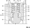
Figure 4 is a sectional elevation view of one of the plunger cartridges shown inFigure 3 ; -
Figure 5 is an elevation view of a vehicle incorporating the check arm assembly shown inFigure 1 ; and -
Figures 6 and7 are flow diagrams illustrating methods of assembly of the check arm keeper shown inFigure 2 . - Reference is made to
Figure 1 , which shows a vehicledoor check assembly 10, in accordance with an embodiment of the present invention. Thecheck assembly 10 is used to control the opening and closing of avehicle door 11 relative to avehicle body 12. Thevehicle body 12 may be any substantially fixed portion of the vehicle, such as the frame and the body panels, . - The
door check assembly 10 includes acheck arm 13 and acheck arm keeper 14. Thecheck arm 13 may be of known construction and has acheck arm body 16 that passes through thekeeper 14. Thebody 16 may have at least one detent 17 thereon. Afirst end 18 of thecheck arm body 16 is pivotally connectable to the vehicle body 12 (Figure 6 ) via a pin joint 19 (Figure 1 ) with amounting bracket 20. At a second end 22 (Figure 1 ) of thecheck arm body 16 is anend stop 24 that engages thecheck arm keeper 14 to limit the maximum opening angle of the vehicle door 12 (Figure 6 ). - The
check arm keeper 14 is mounted to thedoor 12, and includes a keeper housing 26 and at least oneplunger cartridge 28. In the embodiment shown, two plunger cartridges are shown at 28a and 28b respectively. Thecheck arm keeper 14 is shown in more detail inFigures 2-5 . With reference toFigure 3 , thekeeper housing 26 includes amounting bracket portion 30 and at least one cartridge-mounting portion 32 that defines an axis A. Each cartridge-mounting portion 32 lockably receives one of theplunger cartridges 28. In the embodiment shown, there are two such cartridge-mounting portions, shown at 32a and 32b respectively, one for eachplunger cartridge 28, with their axes A aligned with one another. - The
keeper housing 26 may be formed from a contiguous piece of sheet metal. In the embodiment shown, thekeeper housing 26 is formed in a progressive die process wherein first andsecond wings seam 37 at their respective ends shown at 38a and 38b. Once theirends keeper housing 26. As another alternative, thekeeper housing 26 may have any other suitable structure. For example, thekeeper housing 26 may be formed from a polymeric material and may be injection molded. - As shown in
Figure 3 , theplunger cartridges 28 may be mounted to thekeeper housing 26 in facing relationship to one another. Referring toFigure 4 , eachplunger cartridge 28 includes aplunger cartridge housing 40, aplunger 42 and a plunger-biasing member 44. Theplunger cartridge housing 40 is mountable to the keeper housing 26 (Figure 3 ) by any suitable means. For example, the associated cartridge-mountingportion 32 may be generally hollow-cylindrical and may have aninner surface 46. Theplunger cartridge housing 40 may have a radiallyouter wall 48 that is received in the cartridge-mountingportion 32, and locks therewith to resist axial forces on theplunger cartridge housing 40 during use of thedoor check assembly 10. - In the embodiment shown, the locking engagement between the cartridge-mounting
portion 32 and theplunger cartridge housing 40 is provided by any suitable locking structure. In the example shown in the figures, the locking structure may include one ormore locking projections 50 that are engageable with one ormore locking grooves 54. A plurality ofcartridge locking projections 50 are shown inFigure 3 positioned on one of the exterior surface (shown at 52) of the radiallyouter wall 48 of theplunger cartridge housing 40 and theinner surface 46 of the cartridge-mountingportion 32. Eachcartridge locking projection 50 is engageable with acartridge locking groove 54 in the other of theexterior surface 52 of the radiallyouter wall 48 of theplunger cartridge housing 40 and theinner surface 46 of the cartridge-mountingportion 32. In the embodiment shown, theprojection 50 is provided on theinner surface 46 of the cartridge-mountingportion 32 and thegroove 54 is provided on theplunger cartridge housing 40. - The
groove 54 has afirst groove portion 54a that extends generally axially and asecond groove portion 54b that extends generally circumferentially. The first (axial)groove portion 54a permits the axial insertion of theplunger cartridge housing 40 into the cartridge-mountingportion 32 by a selected amount. The second (circumferential)groove portion 54b permits the locking of theplunger cartridge housing 40 against axial forces. While the first andsecond groove portions plunger cartridge housing 40 into the cartridge-mountingportion 32 and the locking of theplunger cartridge housing 40 relative to thekeeper housing 26 against axial forces. - Referring to
Figure 4 , theplunger 42 is slidable in theplunger cartridge housing 40. The plunger-biasing member 44 is positioned in theplunger cartridge housing 40 to urge theplunger 42 out from thehousing 40. Theplunger 42 has afirst engagement member 55 and theplunger cartridge housing 40 has asecond engagement member 56. The first andsecond engagement members plunger 42 is inserted into theplunger cartridge housing 40, but cooperate to retain theplunger 42 in theplunger cartridge housing 40 against a biasing force of the plunger-biasing member 44 when the plunger cartridge is free from thekeeper housing 26. As a result, the components of the plunger cartridge 28 (i.e. theplunger cartridge housing 40, theplunger 42 and the biasing member 44) can be assembled together to form a subassembly that can be formed and then carried as one unit over to thekeeper housing 26 for insertion therein. - Referring to
Figure 4 , thefirst engagement member 55 may be provided on a central projection 57 provided on theplunger 42, while thesecond engagement member 56 may be positioned in aprojection receiving tube 58 provided on theplunger cartridge housing 40. In embodiments wherein the plunger-biasing member 44 is a helical coil compression spring 59, the compression spring may be positioned in surrounding relationship with the central projection 57 and theprojection receiving tube 58, thereby stabilizing the spring 59 during compression of the spring 59, which occurs when theplunger 42 is pushed into theplunger cartridge housing 40. Additionally, a radially outer wall (shown at 60) of theplunger 42 may cooperate with the radiallyouter wall 48 of theplunger cartridge housing 40 to stabilize the spring 59 during compression thereof by surrounding the outside of the spring 59, while the central projection 57 and the receivingtube 58 stabilize the spring 59 from within the central aperture (shown at 61) of the spring 59. It will be further noted that, it is via engagement of the plunger radiallyouter wall 60 with the housing radiallyouter wall 48, and via engagement of the central projection 57 with the receivingtube 58 that sliding engagement is provided between theplunger 42 and theplunger cartridge housing 40. - Mounting of the
plunger cartridge 28 to thekeeper housing 26, (i.e. insertion and locking of theplunger cartridge 28 relative to the keeper housing 26), locks theplunger cartridge housing 40 in a selected axial position relative to thekeeper housing 26 and drives theplunger 42 to a position in which the first andsecond engagement members Figure 4 . - During insertion of the
plunger cartridge 28 into thekeeper housing 26, thecheck arm 13 is already present through thekeeper housing 26. As a result, the biasing force being applied by the biasing member 44 on theplunger cartridge housing 40 and theplunger 42 may be very high as theplunger 42 retracts into theplunger cartridge housing 40 during insertion of theplunger cartridge 28. Theplunger cartridge housing 40 has anaxial end face 62 that has a tool engagement feature 64 (Figure 4 ) having any suitable shape for receiving an axial force and a rotational force. An example shape that is generally a +- shape is shown inFigures 2 and3 . To insert the cartridge 28 (Figure 4 ) into the keeper housing 26 (Figure 3 ), a suitable tool (the tip of which is shown at 66 inFigure 3 ), may be inserted into the tool engagement feature 64 (Figure 4 ), and may be driven axially (either manually by an assembly person or by a suitable machine) to drive theplunger cartridge housing 40 into thekeeper housing 26, thereby compressing the biasing member 44. In the embodiment shown, the tool engagement feature 64 permits theplunger cartridge housing 40 to then be rotated once inserted sufficiently so as to carry the locking projection 53 along thecircumferential portion 54b of the lockinggroove 54, while still maintaining a generally centered compressive force on the biasing member 44. By contrast, in some check arm keepers of the prior art, a tool is used to axially compress a plunger spring, while a cover plate is slid laterally in a slot in a housing to cover the compressed plunger spring. This can be an awkward operation because there is a point at which the tool and the cover plate both occupy the end of the plunger spring, but where neither of them is centered on the end of the plunger spring. By contrast, when assembling thekeeper 14 in accordance with an embodiment of the present invention, the engagement of thetool 66 on theplunger cartridge housing 40 and the engagement of theplunger cartridge housing 40 on the plunger-biasing member 44 remains centered throughout the compression and locking of theplunger cartridge 28 in thekeeper housing 26, thereby facilitating mounting of thecartridge 28 in thekeeper housing 26. Put another way, theplunger cartridge 28 is insertable into the cartridge-mountingportion 32 axially and a suitable axial force (shown at F1 inFigure 3 ) is used to drive theprojections 50 axially along the first portion of thegrooves 54. When theplunger cartridge housing 40 is sufficiently inserted (i.e. when theprojections 50 have reached the bottoms of thefirst groove portions 54a), theplunger cartridge housing 40 is rotatable via rotary force F2 (Figure 3 ), so as to drive theprojections 50 along thesecond portions 54b of thegrooves 54, all while keeping thetool 66 fixed in position in thetool engagement feature 64 so as to maintain an axial force that is generally centered on the plunger-biasing member 44. - It is advantageous that the force exerted on the biasing member 44 that results from engagement of the
tool 66 with theplunger cartridge housing 40 remains centered on the biasing member 44. By contrast, when the force exerted by the tool is offset from the center of the spring, as is the case at some points in time in some embodiments of the prior art, there is a risk that the spring will slip out from the tool and will eject itself from the assembly. - As a separate point, it is advantageous that the
tool 66 remains stationary relative to theplunger cartridge housing 40 and stationary relative to the spring 59 throughout the insertion and locking of theplunger cartridge 28 in thekeeper housing 26. By contrast, in some embodiments of the prior art, as a cover plate is slid in over an end of the spring, the tool that is used to compress the spring is moved laterally to make room for the cover plate to take over holding of the spring in the compressed state. This movement of the tool must be carried out carefully so that the spring does not break free of the tool and eject itself from the assembly, but it must be carried out sufficiently quickly to ensure that there is no interference between the tool and the cover plate being slid into place over end of the spring. - In general, where it is stated that the force exerted on the spring 59 is centered on the spring 59, or that the force exerted by the
tool 66 is centered on the spring 59, it will be understood that the force may be exerted by thetool 66 on a plurality of discrete points on the plunger cartridge housing 40 (e.g. points around the periphery of the housing 40), whereby the net force resulting from the forces at the discrete points is generally centered on the spring 59. - It will be understood that there may be any suitable number of locking
projections 52 andgrooves 54. In the embodiment shown there are fourprojections 52 and fourgrooves 54, spaced apart about the circumferences of the cartridge-mountingportion 32 and theexterior surface 52 of theplunger cartridge housing 40. In some embodiments there could be as few as one projection 53 and onegroove 54, although a plurality ofprojections 52 andgrooves 54 is preferred in at least some embodiments. - The
keeper housing 26 and theplunger cartridges 28 may be considered to be a kit ofparts 100 that is used to form thecheck arm keeper 14. It will be noted that this kit of parts may be an intermediate stage of the manufacture of thecheck arm keeper 14 and in the manufacture of thedoor check assembly 10. In other words, the kit ofparts 100 may exist as aseparate keeper housing 26 andseparate cartridges 28 only temporarily during the manufacture of thekeeper 14 and during the manufacture of thecheck arm assembly 10, while the completedassembly 10 may be what is ultimately sold to a vehicle manufacturer. Nonetheless, manufacture of theassembly 10 by first providing the kit ofparts 100 and then assembling thekeeper 14 and thedoor check assembly 10 from the kit ofparts 100 is advantageous in that the kit ofparts 100 facilitates the process of assembling thekeeper 14 and thedoor check assembly 10. - In the embodiment shown, the
keeper 14 includes two plunger cartridges, however, it will be understood that a check arm keeper could be provided with asingle plunger cartridge 28 that mounts in akeeper housing 26 that includes only one cartridge-mountingportion 32. -
Figure 6 is a flow diagram illustrating amethod 200 of assembling a check arm keeper such as thecheck arm keeper 14 shown inFigures 2 , for engagement with a check arm such ascheck arm 13 to hold a vehicle door in a selected position. The method begins at 202. Atstep 204, a keeper housing (such as keeper housing 26) is provided, and has a generally hollow-cylindrical cartridge-mounting portion (such as cartridge-mounting portion 32) that defines an axis. At step 206 a plunger cartridge (such as plunger cartridge 28) is provided and includes a plunger cartridge housing (such as plunger cartridge housing 40) that is mountable to the cartridge-mounting portion, a plunger (such as plunger 42) that is slidable in the plunger cartridge housing, and a plunger-biasing member (such as biasing member 44) that is positioned in the plunger cartridge housing to urge the plunger out from the plunger cartridge housing. Atstep 208 the plunger cartridge is inserted axially into the cartridge-mounting portion. During the insertion a projection such asprojection 50 on one of an exterior surface of the plunger cartridge housing and an inner surface of the cartridge-mounting portion is driven axially in an axially extending portion of a groove such asgroove 54 in the other of the exterior surface of the plunger cartridge housing and the inner surface of the cartridge-mounting portion. An axially directed force is applied on the plunger cartridge housing that is substantially centered on the plunger-biasing member so as to cause compression of the plunger-biasing member axially. Atstep 210, the plunger cartridge housing is rotated to drive the projection circumferentially in a circumferentially extending portion of the groove, so as to hold the plunger cartridge housing in a selected axial position relative to the keeper housing. The axially directed force is applied on the plunger cartridge housing and is substantially centered on the plunger-biasing member so as to maintain compression of the plunger-biasing member. Themethod 200 ends at 212. -
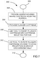
Figure 7 is a flow diagram illustrating anothermethod 300 for assembling a check arm keeper such as thecheck arm keeper 14 for engagement with a check arm such ascheck arm 13 to hold a vehicle door in a selected position. The method starts at 302. At step 304 a keeper housing such askeeper housing 26 is provided and has a generally hollow-cylindrical cartridge-mounting portion such as cartridge-mountingportion 32 that defines an axis. Atstep 306, a plunger cartridge (such as plunger cartridge 28) is provided and includes a plunger cartridge housing such asplunger cartridge housing 40 that is mountable to the cartridge-mounting portion, a plunger such asplunger 42 that is slidable in the plunger cartridge housing, and a plunger-biasing member such as biasing member 44 that is positioned in the plunger cartridge housing to urge the plunger out from the plunger cartridge housing. At step 308 a tool such astool 66 is used to insert the plunger cartridge axially into the cartridge-mounting portion, wherein during said insertion a projection such asprojection 50 on one of an exterior surface of the plunger cartridge housing and an inner surface of the cartridge-mounting portion is driven axially in an axially extending portion of a groove such asgroove 54 in the other of the exterior surface of the plunger cartridge housing and the inner surface of the cartridge-mounting portion. An axially directed force is applied on the plunger cartridge housing on the plunger-biasing member so as to cause compression of the plunger-biasing member axially. Atstep 310 the tool is used to rotate the plunger cartridge housing to drive the projection circumferentially in a circumferentially extending portion of the groove, so as to hold the plunger cartridge housing in a selected axial position relative to the keeper housing, and continuing to apply the axially directed force on the plunger cartridge housing while keeping the tool fixed in position relative to the plunger-biasing member and relative to the plunger cartridge housing. Themethod 300 ends at 312. - While the above description constitutes specific examples, these examples are susceptible to further modification and change without departing from the scope of the invention, as defined by the appended claims.
Claims (7)
- A kit of parts (100) for a check arm keeper (14) for engagement with a check arm (13) to hold a vehicle door (11) in a selected position, comprising:a keeper housing (26) that has a mounting bracket (20) and a cartridge-mounting portion (32); anda plunger cartridge (28) including a plunger cartridge housing (40) that is mountable to the keeper housing (26), a plunger that is slidable in the plunger cartridge housing (40), and a plunger-biasing member (44) that is positioned in the plunger cartridge housing (40) to urge the plunger out from the plunger cartridge housing (40), wherein the plunger has a first engagement member and the plunger cartridge housing (40) has a second engagement member, wherein the first and second engagement members (55, 56) cooperate to retain the plunger in the plunger cartridge housing (40) against a biasing force of the plunger-biasing member (44) when the plunger cartridge (28) is free from the keeper housing (26), and wherein mounting of the plunger cartridge housing (40) holds the plunger cartridge housing (40) in a selected position relative to the keeper housing (26) and drives the plunger to a position in which the first and second engagement members (55, 56) are spaced from one another.
- A kit of parts (100) for a check arm keeper (14) as claimed in claim 1, wherein the plunger cartridge housing (40) has a radially outer wall with an exterior surface that is generally cylindrical, and wherein the keeper housing (26) has a mounting bracket (20) portion that permits mounting of the keeper housing (26) to the vehicle door (11), and a generally hollow-cylindrical cartridge-mounting portion (32) that defines an axis, and that has an inner surface (46) that receives the radially outer wall of the plunger cartridge housing (40) and locks therewith to resist axial forces on the plunger cartridge housing (40).
- A kit of parts (100) for a check arm keeper (14) as claimed in claim 2, wherein a cartridge locking projection is positioned on one of the exterior surface of the radially outer wall of the plunger cartridge housing (40) and the inner surface (46) of the cartridge-mounting portion (32), wherein the cartridge locking projection is engageable with a cartridge locking groove (54) in the other of the exterior surface of the radially outer wall of the plunger cartridge housing (40) and the inner surface (46) of the cartridge-mounting portion (32), wherein the cartridge locking groove (54) has a first groove portion (54a) that extends generally axially and a second groove portion (54b) that extends generally circumferentially.
- A kit of parts (100) for a check arm keeper (14) as claimed in claim 3, wherein a central projection (57) is provided on one of the plunger and the plunger cartridge housing (40) and a projection receiving tube is provided on the other of the plunger and the plunger cartridge housing, wherein the plunger-biasing member (44) is a helical coil compression spring (59) that is positioned in surrounding relationship with the central projection (57) and the projection receiving tube (58) thereby stabilizing the spring (59) during compression.
- A kit of parts (100) for a check arm keeper (14) as claimed in any one of claims 1-4, wherein the keeper housing (26) is formed from a contiguous piece of sheet metal.
- A kit of parts (100) for a check arm keeper (14) as claimed in any one of claims 1-5, wherein the plunger cartridge housing (40) has an axial end face (62) with a tool (66) engagement feature thereon.
- A kit of parts (100) for a check arm keeper (14) as claimed in any one of claims 1-6, wherein the plunger cartridge (28) is a first of two plunger cartridges that are mounted to the keeper housing (26) in facing relationship to one another.
Applications Claiming Priority (2)
| Application Number | Priority Date | Filing Date | Title |
|---|---|---|---|
| US201462022534P | 2014-07-09 | 2014-07-09 | |
| PCT/CA2015/050572 WO2016004521A1 (en) | 2014-07-09 | 2015-06-22 | Improved construction for check arm keeper for check arm assembly for vehicle door |
Publications (3)
| Publication Number | Publication Date |
|---|---|
| EP3167133A1 EP3167133A1 (en) | 2017-05-17 |
| EP3167133A4 EP3167133A4 (en) | 2018-03-28 |
| EP3167133B1 true EP3167133B1 (en) | 2020-01-08 |
Family
ID=55063436
Family Applications (1)
| Application Number | Title | Priority Date | Filing Date |
|---|---|---|---|
| EP15819517.2A Active EP3167133B1 (en) | 2014-07-09 | 2015-06-22 | Improved construction for check arm keeper for check arm assembly for vehicle door |
Country Status (4)
| Country | Link |
|---|---|
| US (1) | US10415280B2 (en) |
| EP (1) | EP3167133B1 (en) |
| CN (1) | CN106471198B (en) |
| WO (1) | WO2016004521A1 (en) |
Families Citing this family (8)
| Publication number | Priority date | Publication date | Assignee | Title |
|---|---|---|---|---|
| JP6734388B2 (en) * | 2016-03-15 | 2020-08-05 | マルチマティック インコーポレーテッドMultimatic Inc. | Vehicle door operating method and door presentation system for vehicle door |
| US9822570B2 (en) * | 2016-03-29 | 2017-11-21 | Ford Global Technologies, Llc | Automatically closing vehicle door |
| CN109577767A (en) * | 2019-01-10 | 2019-04-05 | 上海安宇峰实业有限公司 | A kind of novel position limiter |
| CN111075285A (en) * | 2019-12-31 | 2020-04-28 | 丰业迪睦斯(芜湖)汽车部件有限公司 | Novel metal spring shell structure of limiter |
| EP3960972B1 (en) * | 2020-08-28 | 2026-03-25 | Ningbo Geely Automobile Research & Development Co. Ltd. | A vehicle door system, a vehicle comprising the vehicle door system, and a method for operating a vehicle door system |
| JP7631784B2 (en) | 2020-12-21 | 2025-02-19 | スズキ株式会社 | Door opening adjustment mechanism for vehicle |
| IT202100030530A1 (en) * | 2021-12-02 | 2023-06-02 | De Molli Giancarlo Ind S P A | JOINT FOR DOORS/LEAVES WITH SELECTIVE PARTIAL LOCKING |
| US11965376B2 (en) * | 2022-02-21 | 2024-04-23 | Textron Innovations Inc. | Hinged door open plunger |
Family Cites Families (17)
| Publication number | Priority date | Publication date | Assignee | Title |
|---|---|---|---|---|
| CA1338152C (en) * | 1989-09-28 | 1996-03-12 | Dave Carswell | Door check having a link coated with moldable materials |
| DE4224132C2 (en) * | 1992-07-22 | 2002-11-14 | Stabilus Gmbh | Door locking system |
| US5727287A (en) * | 1997-01-07 | 1998-03-17 | Chrysler Corporation | Check strap assembly for a passenger door of a motor vehicle |
| CN1206122A (en) * | 1997-02-17 | 1999-01-27 | 康宁股份有限公司 | Pump wavelength tuning of optical amplifiers and use of same in wavelength division multiplexed systems |
| US6901630B2 (en) * | 1998-08-07 | 2005-06-07 | Ventra Group, Inc. | Door check device |
| US6446305B1 (en) * | 2000-08-29 | 2002-09-10 | Dura Global Technologies | Rollerless door check mechanism |
| JP3585873B2 (en) * | 2001-08-31 | 2004-11-04 | 理研化機工業株式会社 | Door checker check plate support structure |
| JP3742036B2 (en) * | 2002-07-11 | 2006-02-01 | 理研化機工業株式会社 | Automotive door checker |
| DE20321505U1 (en) * | 2002-10-31 | 2007-09-06 | Edscha Ag | Door fastening has housing together with door frame and opening containing holder bar pretensioned towards brake element |
| DE10302552A1 (en) * | 2003-01-22 | 2004-08-12 | Edscha Ag | A door stay |
| WO2006076757A1 (en) * | 2004-08-30 | 2006-07-27 | M.T.M. Pty Ltd | Door check |
| EP1728949A1 (en) * | 2005-05-31 | 2006-12-06 | Van den Heuvel, Cristiaan Stefanus Lambertus Petru s | Doorstop |
| JP4801806B2 (en) * | 2005-06-20 | 2011-10-26 | 理研化機工業株式会社 | Door hinge with checker |
| KR101456726B1 (en) * | 2006-07-18 | 2014-10-31 | 워렌 인더스트리즈 엘티디. | Integrated hinge assembly with spring biased prop arm |
| ES2396636B1 (en) * | 2010-01-22 | 2014-01-07 | Flexngate Automotive Ibérica S.A. | DOOR RETAINER DEVICE. |
| FR2962149B1 (en) * | 2010-06-30 | 2013-04-26 | Coutier Moulage Gen Ind | DOOR STOP DEVICE FOR MOTOR VEHICLE |
| CN202970207U (en) * | 2012-09-29 | 2013-06-05 | 长城汽车股份有限公司 | Air spring for laterally open type rear back door |
-
2015
- 2015-06-22 EP EP15819517.2A patent/EP3167133B1/en active Active
- 2015-06-22 CN CN201580036992.6A patent/CN106471198B/en not_active Expired - Fee Related
- 2015-06-22 WO PCT/CA2015/050572 patent/WO2016004521A1/en not_active Ceased
-
2017
- 2017-01-09 US US15/401,946 patent/US10415280B2/en not_active Expired - Fee Related
Non-Patent Citations (1)
| Title |
|---|
| None * |
Also Published As
| Publication number | Publication date |
|---|---|
| EP3167133A1 (en) | 2017-05-17 |
| WO2016004521A1 (en) | 2016-01-14 |
| US10415280B2 (en) | 2019-09-17 |
| EP3167133A4 (en) | 2018-03-28 |
| CN106471198B (en) | 2018-08-07 |
| US20170114578A1 (en) | 2017-04-27 |
| CN106471198A (en) | 2017-03-01 |
Similar Documents
| Publication | Publication Date | Title |
|---|---|---|
| US10415280B2 (en) | Construction for check arm keeper for check arm assembly for vehicle door | |
| US8516668B2 (en) | Torque assembly and method of manufacture | |
| DE69521758T2 (en) | Gas revolver gun | |
| CN105849348B (en) | System comprising a component, in particular a door handle, and an actuating device for the component | |
| US5586631A (en) | Window shade | |
| CN111608518B (en) | Actuating device for opening a cover in an actuator manner | |
| EP1947288A2 (en) | Window coverings | |
| US20080262440A1 (en) | Holding Device for Locking the Head of a Syringe Piston on a Syringe Pump Pusher | |
| KR20150043209A (en) | Driven Hatch Arrangement for a Motor Vehicle | |
| KR101213127B1 (en) | Hinge Device And Hinged Door Having The Same | |
| WO2019206362A1 (en) | Motor vehicle lock | |
| JP2019516921A (en) | Spindle drive for displacement components of a motor vehicle | |
| EP2348178B1 (en) | Door retaining device | |
| CN109952410B (en) | Tubular drive mechanism for rolling shutter doors and windows | |
| US20130009352A1 (en) | Damper | |
| US10518744B2 (en) | Webbing take-up device | |
| EP3418985A1 (en) | Device for actuating a signal provider | |
| JP4004359B2 (en) | Locking device | |
| CN219691292U (en) | Door lock structure | |
| US20080083513A1 (en) | Dual-purpose fixing core for a blind | |
| EP3029253A1 (en) | Floor door closer | |
| DE102010060620A1 (en) | Oscillating motor adjuster comprises stator and rotor, from which projection extends through opening located outside central axis in stator wall adjacent to rotor hub | |
| EP1974114B1 (en) | Locking device for functions which can be carried out in particular on vehicles | |
| CN114635615B (en) | Automatic door closing mechanism and refrigerator including the same | |
| CN205854011U (en) | Vehicle block material curtain |
Legal Events
| Date | Code | Title | Description |
|---|---|---|---|
| STAA | Information on the status of an ep patent application or granted ep patent |
Free format text: STATUS: THE INTERNATIONAL PUBLICATION HAS BEEN MADE |
|
| PUAI | Public reference made under article 153(3) epc to a published international application that has entered the european phase |
Free format text: ORIGINAL CODE: 0009012 |
|
| STAA | Information on the status of an ep patent application or granted ep patent |
Free format text: STATUS: REQUEST FOR EXAMINATION WAS MADE |
|
| 17P | Request for examination filed |
Effective date: 20170209 |
|
| AK | Designated contracting states |
Kind code of ref document: A1 Designated state(s): AL AT BE BG CH CY CZ DE DK EE ES FI FR GB GR HR HU IE IS IT LI LT LU LV MC MK MT NL NO PL PT RO RS SE SI SK SM TR |
|
| AX | Request for extension of the european patent |
Extension state: BA ME |
|
| DAV | Request for validation of the european patent (deleted) | ||
| DAX | Request for extension of the european patent (deleted) | ||
| A4 | Supplementary search report drawn up and despatched |
Effective date: 20180228 |
|
| RIC1 | Information provided on ipc code assigned before grant |
Ipc: E05C 17/04 20060101AFI20180222BHEP Ipc: B60J 5/04 20060101ALI20180222BHEP Ipc: E05C 17/20 20060101ALI20180222BHEP Ipc: E05F 5/00 20170101ALI20180222BHEP Ipc: B05C 19/00 20060101ALI20180222BHEP |
|
| GRAP | Despatch of communication of intention to grant a patent |
Free format text: ORIGINAL CODE: EPIDOSNIGR1 |
|
| STAA | Information on the status of an ep patent application or granted ep patent |
Free format text: STATUS: GRANT OF PATENT IS INTENDED |
|
| RIC1 | Information provided on ipc code assigned before grant |
Ipc: E05F 5/00 20170101ALI20190305BHEP Ipc: B05C 19/00 20060101ALI20190305BHEP Ipc: E05C 17/04 20060101AFI20190305BHEP Ipc: B60J 5/04 20060101ALI20190305BHEP Ipc: E05C 17/20 20060101ALI20190305BHEP |
|
| INTG | Intention to grant announced |
Effective date: 20190322 |
|
| GRAJ | Information related to disapproval of communication of intention to grant by the applicant or resumption of examination proceedings by the epo deleted |
Free format text: ORIGINAL CODE: EPIDOSDIGR1 |
|
| STAA | Information on the status of an ep patent application or granted ep patent |
Free format text: STATUS: REQUEST FOR EXAMINATION WAS MADE |
|
| GRAP | Despatch of communication of intention to grant a patent |
Free format text: ORIGINAL CODE: EPIDOSNIGR1 |
|
| STAA | Information on the status of an ep patent application or granted ep patent |
Free format text: STATUS: GRANT OF PATENT IS INTENDED |
|
| INTG | Intention to grant announced |
Effective date: 20190814 |
|
| GRAS | Grant fee paid |
Free format text: ORIGINAL CODE: EPIDOSNIGR3 |
|
| GRAA | (expected) grant |
Free format text: ORIGINAL CODE: 0009210 |
|
| STAA | Information on the status of an ep patent application or granted ep patent |
Free format text: STATUS: THE PATENT HAS BEEN GRANTED |
|
| AK | Designated contracting states |
Kind code of ref document: B1 Designated state(s): AL AT BE BG CH CY CZ DE DK EE ES FI FR GB GR HR HU IE IS IT LI LT LU LV MC MK MT NL NO PL PT RO RS SE SI SK SM TR |
|
| REG | Reference to a national code |
Ref country code: GB Ref legal event code: FG4D |
|
| REG | Reference to a national code |
Ref country code: CH Ref legal event code: EP |
|
| REG | Reference to a national code |
Ref country code: DE Ref legal event code: R096 Ref document number: 602015045308 Country of ref document: DE |
|
| REG | Reference to a national code |
Ref country code: IE Ref legal event code: FG4D |
|
| REG | Reference to a national code |
Ref country code: AT Ref legal event code: REF Ref document number: 1222911 Country of ref document: AT Kind code of ref document: T Effective date: 20200215 |
|
| REG | Reference to a national code |
Ref country code: NL Ref legal event code: MP Effective date: 20200108 |
|
| REG | Reference to a national code |
Ref country code: LT Ref legal event code: MG4D |
|
| PG25 | Lapsed in a contracting state [announced via postgrant information from national office to epo] |
Ref country code: PT Free format text: LAPSE BECAUSE OF FAILURE TO SUBMIT A TRANSLATION OF THE DESCRIPTION OR TO PAY THE FEE WITHIN THE PRESCRIBED TIME-LIMIT Effective date: 20200531 Ref country code: NL Free format text: LAPSE BECAUSE OF FAILURE TO SUBMIT A TRANSLATION OF THE DESCRIPTION OR TO PAY THE FEE WITHIN THE PRESCRIBED TIME-LIMIT Effective date: 20200108 Ref country code: LT Free format text: LAPSE BECAUSE OF FAILURE TO SUBMIT A TRANSLATION OF THE DESCRIPTION OR TO PAY THE FEE WITHIN THE PRESCRIBED TIME-LIMIT Effective date: 20200108 Ref country code: NO Free format text: LAPSE BECAUSE OF FAILURE TO SUBMIT A TRANSLATION OF THE DESCRIPTION OR TO PAY THE FEE WITHIN THE PRESCRIBED TIME-LIMIT Effective date: 20200408 Ref country code: FI Free format text: LAPSE BECAUSE OF FAILURE TO SUBMIT A TRANSLATION OF THE DESCRIPTION OR TO PAY THE FEE WITHIN THE PRESCRIBED TIME-LIMIT Effective date: 20200108 Ref country code: RS Free format text: LAPSE BECAUSE OF FAILURE TO SUBMIT A TRANSLATION OF THE DESCRIPTION OR TO PAY THE FEE WITHIN THE PRESCRIBED TIME-LIMIT Effective date: 20200108 |
|
| PG25 | Lapsed in a contracting state [announced via postgrant information from national office to epo] |
Ref country code: IS Free format text: LAPSE BECAUSE OF FAILURE TO SUBMIT A TRANSLATION OF THE DESCRIPTION OR TO PAY THE FEE WITHIN THE PRESCRIBED TIME-LIMIT Effective date: 20200508 Ref country code: LV Free format text: LAPSE BECAUSE OF FAILURE TO SUBMIT A TRANSLATION OF THE DESCRIPTION OR TO PAY THE FEE WITHIN THE PRESCRIBED TIME-LIMIT Effective date: 20200108 Ref country code: SE Free format text: LAPSE BECAUSE OF FAILURE TO SUBMIT A TRANSLATION OF THE DESCRIPTION OR TO PAY THE FEE WITHIN THE PRESCRIBED TIME-LIMIT Effective date: 20200108 Ref country code: HR Free format text: LAPSE BECAUSE OF FAILURE TO SUBMIT A TRANSLATION OF THE DESCRIPTION OR TO PAY THE FEE WITHIN THE PRESCRIBED TIME-LIMIT Effective date: 20200108 Ref country code: GR Free format text: LAPSE BECAUSE OF FAILURE TO SUBMIT A TRANSLATION OF THE DESCRIPTION OR TO PAY THE FEE WITHIN THE PRESCRIBED TIME-LIMIT Effective date: 20200409 Ref country code: BG Free format text: LAPSE BECAUSE OF FAILURE TO SUBMIT A TRANSLATION OF THE DESCRIPTION OR TO PAY THE FEE WITHIN THE PRESCRIBED TIME-LIMIT Effective date: 20200408 |
|
| REG | Reference to a national code |
Ref country code: DE Ref legal event code: R097 Ref document number: 602015045308 Country of ref document: DE |
|
| PG25 | Lapsed in a contracting state [announced via postgrant information from national office to epo] |
Ref country code: SM Free format text: LAPSE BECAUSE OF FAILURE TO SUBMIT A TRANSLATION OF THE DESCRIPTION OR TO PAY THE FEE WITHIN THE PRESCRIBED TIME-LIMIT Effective date: 20200108 Ref country code: EE Free format text: LAPSE BECAUSE OF FAILURE TO SUBMIT A TRANSLATION OF THE DESCRIPTION OR TO PAY THE FEE WITHIN THE PRESCRIBED TIME-LIMIT Effective date: 20200108 Ref country code: CZ Free format text: LAPSE BECAUSE OF FAILURE TO SUBMIT A TRANSLATION OF THE DESCRIPTION OR TO PAY THE FEE WITHIN THE PRESCRIBED TIME-LIMIT Effective date: 20200108 Ref country code: RO Free format text: LAPSE BECAUSE OF FAILURE TO SUBMIT A TRANSLATION OF THE DESCRIPTION OR TO PAY THE FEE WITHIN THE PRESCRIBED TIME-LIMIT Effective date: 20200108 Ref country code: ES Free format text: LAPSE BECAUSE OF FAILURE TO SUBMIT A TRANSLATION OF THE DESCRIPTION OR TO PAY THE FEE WITHIN THE PRESCRIBED TIME-LIMIT Effective date: 20200108 Ref country code: DK Free format text: LAPSE BECAUSE OF FAILURE TO SUBMIT A TRANSLATION OF THE DESCRIPTION OR TO PAY THE FEE WITHIN THE PRESCRIBED TIME-LIMIT Effective date: 20200108 Ref country code: SK Free format text: LAPSE BECAUSE OF FAILURE TO SUBMIT A TRANSLATION OF THE DESCRIPTION OR TO PAY THE FEE WITHIN THE PRESCRIBED TIME-LIMIT Effective date: 20200108 |
|
| PLBE | No opposition filed within time limit |
Free format text: ORIGINAL CODE: 0009261 |
|
| STAA | Information on the status of an ep patent application or granted ep patent |
Free format text: STATUS: NO OPPOSITION FILED WITHIN TIME LIMIT |
|
| REG | Reference to a national code |
Ref country code: AT Ref legal event code: MK05 Ref document number: 1222911 Country of ref document: AT Kind code of ref document: T Effective date: 20200108 |
|
| 26N | No opposition filed |
Effective date: 20201009 |
|
| PG25 | Lapsed in a contracting state [announced via postgrant information from national office to epo] |
Ref country code: MC Free format text: LAPSE BECAUSE OF FAILURE TO SUBMIT A TRANSLATION OF THE DESCRIPTION OR TO PAY THE FEE WITHIN THE PRESCRIBED TIME-LIMIT Effective date: 20200108 Ref country code: IT Free format text: LAPSE BECAUSE OF FAILURE TO SUBMIT A TRANSLATION OF THE DESCRIPTION OR TO PAY THE FEE WITHIN THE PRESCRIBED TIME-LIMIT Effective date: 20200108 Ref country code: AT Free format text: LAPSE BECAUSE OF FAILURE TO SUBMIT A TRANSLATION OF THE DESCRIPTION OR TO PAY THE FEE WITHIN THE PRESCRIBED TIME-LIMIT Effective date: 20200108 |
|
| REG | Reference to a national code |
Ref country code: CH Ref legal event code: PL |
|
| PG25 | Lapsed in a contracting state [announced via postgrant information from national office to epo] |
Ref country code: SI Free format text: LAPSE BECAUSE OF FAILURE TO SUBMIT A TRANSLATION OF THE DESCRIPTION OR TO PAY THE FEE WITHIN THE PRESCRIBED TIME-LIMIT Effective date: 20200108 Ref country code: PL Free format text: LAPSE BECAUSE OF FAILURE TO SUBMIT A TRANSLATION OF THE DESCRIPTION OR TO PAY THE FEE WITHIN THE PRESCRIBED TIME-LIMIT Effective date: 20200108 |
|
| PG25 | Lapsed in a contracting state [announced via postgrant information from national office to epo] |
Ref country code: LU Free format text: LAPSE BECAUSE OF NON-PAYMENT OF DUE FEES Effective date: 20200622 |
|
| REG | Reference to a national code |
Ref country code: BE Ref legal event code: MM Effective date: 20200630 |
|
| PG25 | Lapsed in a contracting state [announced via postgrant information from national office to epo] |
Ref country code: CH Free format text: LAPSE BECAUSE OF NON-PAYMENT OF DUE FEES Effective date: 20200630 Ref country code: IE Free format text: LAPSE BECAUSE OF NON-PAYMENT OF DUE FEES Effective date: 20200622 Ref country code: LI Free format text: LAPSE BECAUSE OF NON-PAYMENT OF DUE FEES Effective date: 20200630 |
|
| PG25 | Lapsed in a contracting state [announced via postgrant information from national office to epo] |
Ref country code: BE Free format text: LAPSE BECAUSE OF NON-PAYMENT OF DUE FEES Effective date: 20200630 |
|
| PG25 | Lapsed in a contracting state [announced via postgrant information from national office to epo] |
Ref country code: TR Free format text: LAPSE BECAUSE OF FAILURE TO SUBMIT A TRANSLATION OF THE DESCRIPTION OR TO PAY THE FEE WITHIN THE PRESCRIBED TIME-LIMIT Effective date: 20200108 Ref country code: MT Free format text: LAPSE BECAUSE OF FAILURE TO SUBMIT A TRANSLATION OF THE DESCRIPTION OR TO PAY THE FEE WITHIN THE PRESCRIBED TIME-LIMIT Effective date: 20200108 Ref country code: CY Free format text: LAPSE BECAUSE OF FAILURE TO SUBMIT A TRANSLATION OF THE DESCRIPTION OR TO PAY THE FEE WITHIN THE PRESCRIBED TIME-LIMIT Effective date: 20200108 |
|
| PG25 | Lapsed in a contracting state [announced via postgrant information from national office to epo] |
Ref country code: MK Free format text: LAPSE BECAUSE OF FAILURE TO SUBMIT A TRANSLATION OF THE DESCRIPTION OR TO PAY THE FEE WITHIN THE PRESCRIBED TIME-LIMIT Effective date: 20200108 Ref country code: AL Free format text: LAPSE BECAUSE OF FAILURE TO SUBMIT A TRANSLATION OF THE DESCRIPTION OR TO PAY THE FEE WITHIN THE PRESCRIBED TIME-LIMIT Effective date: 20200108 |
|
| PGFP | Annual fee paid to national office [announced via postgrant information from national office to epo] |
Ref country code: GB Payment date: 20220627 Year of fee payment: 8 Ref country code: DE Payment date: 20220630 Year of fee payment: 8 |
|
| PGFP | Annual fee paid to national office [announced via postgrant information from national office to epo] |
Ref country code: FR Payment date: 20220624 Year of fee payment: 8 |
|
| REG | Reference to a national code |
Ref country code: DE Ref legal event code: R119 Ref document number: 602015045308 Country of ref document: DE |
|
| GBPC | Gb: european patent ceased through non-payment of renewal fee |
Effective date: 20230622 |
|
| PG25 | Lapsed in a contracting state [announced via postgrant information from national office to epo] |
Ref country code: DE Free format text: LAPSE BECAUSE OF NON-PAYMENT OF DUE FEES Effective date: 20240103 Ref country code: GB Free format text: LAPSE BECAUSE OF NON-PAYMENT OF DUE FEES Effective date: 20230622 |
|
| PG25 | Lapsed in a contracting state [announced via postgrant information from national office to epo] |
Ref country code: FR Free format text: LAPSE BECAUSE OF NON-PAYMENT OF DUE FEES Effective date: 20230630 |