EP3166304A1 - Camera with light-guide array for camera automated vehicles - Google Patents
Camera with light-guide array for camera automated vehicles Download PDFInfo
- Publication number
- EP3166304A1 EP3166304A1 EP16197177.5A EP16197177A EP3166304A1 EP 3166304 A1 EP3166304 A1 EP 3166304A1 EP 16197177 A EP16197177 A EP 16197177A EP 3166304 A1 EP3166304 A1 EP 3166304A1
- Authority
- EP
- European Patent Office
- Prior art keywords
- light
- lens
- imager
- camera
- guide
- Prior art date
- Legal status (The legal status is an assumption and is not a legal conclusion. Google has not performed a legal analysis and makes no representation as to the accuracy of the status listed.)
- Withdrawn
Links
- 238000006073 displacement reaction Methods 0.000 claims description 2
- 239000000463 material Substances 0.000 description 3
- 230000000694 effects Effects 0.000 description 2
- 238000003384 imaging method Methods 0.000 description 2
- 150000001875 compounds Chemical class 0.000 description 1
- 238000005094 computer simulation Methods 0.000 description 1
- 238000010276 construction Methods 0.000 description 1
- 238000001914 filtration Methods 0.000 description 1
- 230000007774 longterm Effects 0.000 description 1
- 238000004519 manufacturing process Methods 0.000 description 1
- 239000011159 matrix material Substances 0.000 description 1
- 238000000034 method Methods 0.000 description 1
- 238000000465 moulding Methods 0.000 description 1
- 230000003287 optical effect Effects 0.000 description 1
Images


Classifications
-
- H—ELECTRICITY
- H04—ELECTRIC COMMUNICATION TECHNIQUE
- H04N—PICTORIAL COMMUNICATION, e.g. TELEVISION
- H04N23/00—Cameras or camera modules comprising electronic image sensors; Control thereof
- H04N23/50—Constructional details
- H04N23/54—Mounting of pick-up tubes, electronic image sensors, deviation or focusing coils
-
- G—PHYSICS
- G02—OPTICS
- G02B—OPTICAL ELEMENTS, SYSTEMS OR APPARATUS
- G02B27/00—Optical systems or apparatus not provided for by any of the groups G02B1/00 - G02B26/00, G02B30/00
- G02B27/0075—Optical systems or apparatus not provided for by any of the groups G02B1/00 - G02B26/00, G02B30/00 with means for altering, e.g. increasing, the depth of field or depth of focus
-
- G—PHYSICS
- G02—OPTICS
- G02B—OPTICAL ELEMENTS, SYSTEMS OR APPARATUS
- G02B27/00—Optical systems or apparatus not provided for by any of the groups G02B1/00 - G02B26/00, G02B30/00
- G02B27/09—Beam shaping, e.g. changing the cross-sectional area, not otherwise provided for
- G02B27/0911—Anamorphotic systems
-
- G—PHYSICS
- G02—OPTICS
- G02B—OPTICAL ELEMENTS, SYSTEMS OR APPARATUS
- G02B27/00—Optical systems or apparatus not provided for by any of the groups G02B1/00 - G02B26/00, G02B30/00
- G02B27/09—Beam shaping, e.g. changing the cross-sectional area, not otherwise provided for
- G02B27/0938—Using specific optical elements
- G02B27/095—Refractive optical elements
- G02B27/0972—Prisms
-
- G—PHYSICS
- G02—OPTICS
- G02B—OPTICAL ELEMENTS, SYSTEMS OR APPARATUS
- G02B3/00—Simple or compound lenses
- G02B3/0006—Arrays
-
- G—PHYSICS
- G02—OPTICS
- G02B—OPTICAL ELEMENTS, SYSTEMS OR APPARATUS
- G02B3/00—Simple or compound lenses
- G02B3/0006—Arrays
- G02B3/0037—Arrays characterized by the distribution or form of lenses
- G02B3/0056—Arrays characterized by the distribution or form of lenses arranged along two different directions in a plane, e.g. honeycomb arrangement of lenses
-
- G—PHYSICS
- G02—OPTICS
- G02B—OPTICAL ELEMENTS, SYSTEMS OR APPARATUS
- G02B5/00—Optical elements other than lenses
- G02B5/04—Prisms
- G02B5/045—Prism arrays
-
- G—PHYSICS
- G02—OPTICS
- G02B—OPTICAL ELEMENTS, SYSTEMS OR APPARATUS
- G02B5/00—Optical elements other than lenses
- G02B5/20—Filters
- G02B5/201—Filters in the form of arrays
-
- H—ELECTRICITY
- H04—ELECTRIC COMMUNICATION TECHNIQUE
- H04N—PICTORIAL COMMUNICATION, e.g. TELEVISION
- H04N23/00—Cameras or camera modules comprising electronic image sensors; Control thereof
- H04N23/10—Cameras or camera modules comprising electronic image sensors; Control thereof for generating image signals from different wavelengths
-
- H—ELECTRICITY
- H04—ELECTRIC COMMUNICATION TECHNIQUE
- H04N—PICTORIAL COMMUNICATION, e.g. TELEVISION
- H04N23/00—Cameras or camera modules comprising electronic image sensors; Control thereof
- H04N23/50—Constructional details
- H04N23/51—Housings
-
- H—ELECTRICITY
- H04—ELECTRIC COMMUNICATION TECHNIQUE
- H04N—PICTORIAL COMMUNICATION, e.g. TELEVISION
- H04N23/00—Cameras or camera modules comprising electronic image sensors; Control thereof
- H04N23/56—Cameras or camera modules comprising electronic image sensors; Control thereof provided with illuminating means
-
- H—ELECTRICITY
- H10—SEMICONDUCTOR DEVICES; ELECTRIC SOLID-STATE DEVICES NOT OTHERWISE PROVIDED FOR
- H10F—INORGANIC SEMICONDUCTOR DEVICES SENSITIVE TO INFRARED RADIATION, LIGHT, ELECTROMAGNETIC RADIATION OF SHORTER WAVELENGTH OR CORPUSCULAR RADIATION
- H10F39/00—Integrated devices, or assemblies of multiple devices, comprising at least one element covered by group H10F30/00, e.g. radiation detectors comprising photodiode arrays
- H10F39/80—Constructional details of image sensors
- H10F39/806—Optical elements or arrangements associated with the image sensors
- H10F39/8063—Microlenses
-
- B—PERFORMING OPERATIONS; TRANSPORTING
- B60—VEHICLES IN GENERAL
- B60R—VEHICLES, VEHICLE FITTINGS, OR VEHICLE PARTS, NOT OTHERWISE PROVIDED FOR
- B60R2300/00—Details of viewing arrangements using cameras and displays, specially adapted for use in a vehicle
- B60R2300/10—Details of viewing arrangements using cameras and displays, specially adapted for use in a vehicle characterised by the type of camera system used
-
- B—PERFORMING OPERATIONS; TRANSPORTING
- B60—VEHICLES IN GENERAL
- B60R—VEHICLES, VEHICLE FITTINGS, OR VEHICLE PARTS, NOT OTHERWISE PROVIDED FOR
- B60R2300/00—Details of viewing arrangements using cameras and displays, specially adapted for use in a vehicle
- B60R2300/80—Details of viewing arrangements using cameras and displays, specially adapted for use in a vehicle characterised by the intended use of the viewing arrangement
-
- B—PERFORMING OPERATIONS; TRANSPORTING
- B60—VEHICLES IN GENERAL
- B60Y—INDEXING SCHEME RELATING TO ASPECTS CROSS-CUTTING VEHICLE TECHNOLOGY
- B60Y2400/00—Special features of vehicle units
- B60Y2400/30—Sensors
- B60Y2400/301—Sensors for position or displacement
- B60Y2400/3015—Optical cameras
-
- H—ELECTRICITY
- H04—ELECTRIC COMMUNICATION TECHNIQUE
- H04N—PICTORIAL COMMUNICATION, e.g. TELEVISION
- H04N23/00—Cameras or camera modules comprising electronic image sensors; Control thereof
- H04N23/50—Constructional details
- H04N23/55—Optical parts specially adapted for electronic image sensors; Mounting thereof
Definitions
- This disclosure generally relates to a camera suitable for use on an automated vehicle, and more particularly relates to an array of light-guides interposed between a lens-module and an imager-device, where an imager end of each light-guide has an angle based on a chief-ray-angle (CRA) of light from the lens-module.
- CRA chief-ray-angle
- Described herein is a camera that adds an array of light-guides to allow the use of a lower cost lens-module with better optical performance, lower cost, but larger maximum CRA to be used on imaging devices with a smaller prescribed maximum CRA. This is achieved by refracting larger CRA ray bundles exiting the lens toward individual pixels of an imager-device via an array of light-guides, where each light-guide is aligned with a corresponding pixel.
- a camera suitable for use on an automated vehicle includes an imager-device, a lens-module, and an array of light-guides.
- the imager-device is operable to determine an image.
- the imager-device includes a plurality of light-detecting pixels, and each pixel is overlaid with a micro-lens.
- the lens-module is operable to direct light from a field-of-view of the camera toward the imager-device.
- the array of light-guides is interposed between the lens-module and the imager-device. The array is arranged so each instance of light-guide is aligned with a corresponding instance of micro-lens.
- Each light-guide is defined by a lens-end and an imager-end.
- the lens-end of each of the light-guides cooperates to define a planar-surface of the array.
- the imager-end of the light-guide is characterized by an angle selected to direct light within the light-guide toward the corresponding instance of the micro-lens. The angle is determined based on a chief-ray-angle (CRA) of light from the lens-module impinging on the lens-end.
- CRA chief-ray-angle
- Fig. 1 illustrates a non-limiting example of a camera 10 suitable for use on an automated vehicle (not shown).
- a fully automated vehicle i.e. an autonomous vehicle
- a vehicle that is partially automated i.e. a vehicle that is generally driven by an operator (not shown) but provides assistance to the operator when necessary to, for example, detect/avoid an impending collision.
- the camera 10 described herein provides for a low cost, wide field-of-view camera design that is well-suited for automotive applications.
- teachings presented herein are also applicable to non-automotive applications such as a stand-alone, purpose-built camera, or a camera integrated into another device such as a smart-phone or tablet.
- the camera 10 includes an imager-device 12 operable to determine or output an image 14 to, for example, a processor 16.
- the processor 16 may include a general-purpose type processor such as a microprocessor, a purpose built image-processor, or other control circuitry such as analog and/or digital control circuitry including an application specific integrated circuit (ASIC) for processing the image 14 as should be evident to those in the art.
- the processor 16 may communicate with memory 18, including non-volatile memory, such as electrically erasable programmable read-only memory (EEPROM) for storing one or more instances of the image 14 for the purpose of relatively long-term storage, or further image processing.
- EEPROM electrically erasable programmable read-only memory
- the imager-device 12 generally includes a plurality of light-detecting pixels 20, each pixel overlaid with a micro-lens 22, the purpose and construction of which is well-known. While the illustration shows six instances of the pixels 20, this is only to simplify the illustration and due to the perspective, see Fig. 2A . It is recognized that that commercially-available examples of the imager-device have thousands of pixels, for example a matrix of 1280x960 pixels. However, it is also known that there is a limit to the chief-ray-angle, hereafter the CRA 24, which the imager-device 12 can tolerate and still effectively capture the image 14.
- the image 14 may be degraded around the perimeter because the amount of light 26 impinging on an instance of the micro-lens 22 and directed to a corresponding instance of the pixels 20 is reduced.
- the imager-device 12 also generally includes a lens-module 30 operable to direct light from a field-of-view 32 of the camera 10 toward the imager-device 12.
- a lens-module 30 operable to direct light from a field-of-view 32 of the camera 10 toward the imager-device 12.
- the cost of the lens-module 30 undesirable increases.
- the cost of the lens-module 30 could be reduced while still providing the field-of-view 32 that is desired if a larger value of the CRA 24 could be utilized.
- the camera 10 advantageously includes an array 34 of light-guides 36 interposed between the lens-module 30 and the imager-device 12.
- the array 34 is arranged so each instance of light-guide 36 is aligned with a corresponding instance of micro-lens 22.
- Figs. 2A and 2B show further non-limiting details of the array 34 and the light-guides 36 that form the array 34.
- Each light-guide is defined by a lens-end 38 of the light-guide 36 oriented toward the lens-module 30, and an imager-end 40 of the light-guide 36 oriented toward the imager-device 12.
- the lens-end 38 of each of the light-guides 36 cooperates to define a planar-surface 42 of the array 34. That is, the lens-ends 38 of all of the light-guides 36 that form the array 34 are co-planar.
- the array 34 may be fabricated by molding or other known means used to fabricate the micro-lens 22.
- the imager-end 40 of each of the light-guides 36 is characterized by an angle 44 that is selected to direct light within the light-guide 36 toward the corresponding instance of the micro-lens 22.
- the angle is determined based on the CRA 24 of the light 26 from the lens-module 30 that is impinging on the lens-end 38, i.e. the planar surface 42.
- the angle 44 may be a compound angle that can be expressed in terms of an azimuth-angle 44A and/or a tilt-angle 44B.
- Computer modeling of the camera 10 that includes a suitable example of the array 34 overlaying the imager-device 12 as described herein indicates that as a result of adding the array 34, the lens-module 30 can be configured so the maximum value of the CRA 24 impinging on the array 34 is thirty-one degrees (31 °) rather than the previously suggested limit for a camera with a similar example of the imager-device 12 but without the array 34.
- This performance is realized for a light-guide formed by material with an index of refraction of 1.8 and having the angle 44 set at twenty-seven degrees (27°) where a zero degree tilt of the imager-end 40 is parallel to the planar surface 42.
- the imager-device may be characterized as defining a center-point 46.
- the angle 44 may then be characterized as being determined based on a profile (e.g. a graphical curve or a non-linear equation) of the lens-module 30 that characterizes the CRA 24 versus a distance 48 of the corresponding instance of the micro-lens 22 from the center-point 46.
- a profile e.g. a graphical curve or a non-linear equation
- instances of the light-guides 36 near the center-point may not require the imager-end to be angled. That is, as shown in Fig. 2A , the imager-end 40 of the light-guides 36 proximate to the center-point may be coplanar similar to the lens-end 38 of those instances of the light-guides 36.
- Fig. 3 shows further non-limiting details of the camera 10.
- typical examples of the lens-module 30 ( Fig. 1 ) with a relatively wide-angle for the field-of-view 32 will exhibit a substantial focal-field curvature so that light detected by the pixels 20 near the center-point 46 may be well-focused, while light detected by the pixels 20 that are substantially distant from the center-point 46, i.e. at the periphery of the imager-device 12 are not well-focused. This problem is further exacerbated if the imager-device 12 is a relatively large format sensor.
- the array 34 may be advantageously configured so each of the light-guides 36 is characterized by a guide-length 50 indicative of a distance between the lens-end 38 and the imager-end 40.
- the back focal length (BFL) of respective instance of the light-guide 36 increases, such that the focal point is shifted further to the image plane at the outer field where field curvature of lens causes defocus.
- array 34 By configuring the array 34 so the guide-length 50 of the light-guides 36 is smaller or shorter near the center-point 46 when compared to the guide-length 50 of the light-guides 36 that are distant or well displaced from the center-point 46, array 34 will help to flatten the field curvature further to provide a more uniformly focused image across the imager-device.
- the guide-length 50A is less than the guide-length 50B.
- the guide-length 50 of each of the light-guides 36 increases as the displacement of the light-guide 36 from the center-point 46 increases.
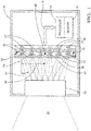
- Fig. 4 illustrates further non-limiting details of the array 34 where each of the light-guides 36 includes or is equipped with a filter-element 52.
- the filter-element is located at or applied to the lens-end 38 if each of the light-guides 36, however this is not a requirement.
- the filter-element could be applied to the imager-end 40, or could be integrated in to the material used to form the each of the light-guides, i.e. the material used to form the light-guides 36 could be colored or tinted.
- the filtering effect of each of the light-guides 36 be uniquely determined as suggested by the red (R), green (G), and blue (B) instances of the filter-elements 52 shown in Fig. 4 , then applying the filter-element 52 upon the lens-end 38 may be preferable for manufacturing reasons so as to simplify the assembly process of the camera 10 by reducing the total part count.
- a camera 10 that includes an array 34 of light-guides 36 which.
- the array is effective to increase the maximum allowable CRA of the imaging device so as to allow the use of larger CRA lens module, and thereby provides for a camera with better performance, smaller in size and lower in cost.
- the guide-length 50 of the light-guides 36 can be varied to correct for focal-field curvature and thereby improve the clarity of images for cameras with wide fields-of-view.
Landscapes
- Physics & Mathematics (AREA)
- General Physics & Mathematics (AREA)
- Optics & Photonics (AREA)
- Engineering & Computer Science (AREA)
- Multimedia (AREA)
- Signal Processing (AREA)
- Transforming Light Signals Into Electric Signals (AREA)
- Studio Devices (AREA)
- Mechanical Engineering (AREA)
Abstract
A camera (10) suitable for use on an automated vehicle includes an imager-device (12), a lens-module (30), and an array (34) of light-guides (36). The imager-device (12) is operable to determine an image (14) and includes a plurality of light-detecting pixels (20). Each pixel is overlaid with a micro-lens (22). The lens-module (30) directs light (26) from a field-of-view (32) of the camera (10) toward the imager-device (12). The array (34) of light-guides (36) is interposed between the lens-module (30) and the imager-device (12), and is arranged so each instance of light-guide (36) is aligned with a corresponding instance of micro-lens (22). Each light-guide (36) is defined by a lens-end (38) and an imager-end (40). The lens-end (38) of each of the light-guides (36) cooperates to define a planar-surface (42) of the array (34), and imager-end (40) of the light-guide (36) is characterized by an angle (44) selected to direct light (26) within the light-guide (36) toward the corresponding instance of the micro-lens (22). The angle (44) is determined based on a chief-ray-angle (24) (CRA (24)) of light (26) from the lens-module (30) impinging on the lens-end (38).
Description
- This disclosure generally relates to a camera suitable for use on an automated vehicle, and more particularly relates to an array of light-guides interposed between a lens-module and an imager-device, where an imager end of each light-guide has an angle based on a chief-ray-angle (CRA) of light from the lens-module.
- It is desirable to decrease the cost and size of a camera. One way is to select a lens-assembly or lens-module that provides an increased chief-ray-angle (CRA) as a camera that uses a lens-module designed with a smaller prescribed maximum CRA is generally more expensive and larger in size. However, pixels located near the perimeter of an imager-device may suffer from unacceptable roll-off when the chief ray angle becomes quite steep. This is especially true in applications for wide angular field-of-view (short focal length) applications. It has been suggested to equip the imager-device with micro-lenses in an effort to increase the amount of light making it to the active pixel area. However, like other lenses, micro-lenses have an angular acceptance in which they operate most efficiently. As the angle of incidence increases, the amount of light that makes it to the active area of the pixel is reduced. Many lens designs attempt to keep their image space chief ray angles less than seven degrees in order to reduce these effects. It has also been suggested to use a half telecentric type lens so the CRA at the focal plane is near to 0 degree, but doing so undesirably increases the cost and size of the camera.
- Described herein is a camera that adds an array of light-guides to allow the use of a lower cost lens-module with better optical performance, lower cost, but larger maximum CRA to be used on imaging devices with a smaller prescribed maximum CRA. This is achieved by refracting larger CRA ray bundles exiting the lens toward individual pixels of an imager-device via an array of light-guides, where each light-guide is aligned with a corresponding pixel.
- In accordance with one embodiment, a camera suitable for use on an automated vehicle is provided. The camera includes an imager-device, a lens-module, and an array of light-guides. The imager-device is operable to determine an image. The imager-device includes a plurality of light-detecting pixels, and each pixel is overlaid with a micro-lens. The lens-module is operable to direct light from a field-of-view of the camera toward the imager-device. The array of light-guides is interposed between the lens-module and the imager-device. The array is arranged so each instance of light-guide is aligned with a corresponding instance of micro-lens. Each light-guide is defined by a lens-end and an imager-end. The lens-end of each of the light-guides cooperates to define a planar-surface of the array. The imager-end of the light-guide is characterized by an angle selected to direct light within the light-guide toward the corresponding instance of the micro-lens. The angle is determined based on a chief-ray-angle (CRA) of light from the lens-module impinging on the lens-end.
- Further features and advantages will appear more clearly on a reading of the following detailed description of the preferred embodiment, which is given by way of non-limiting example only and with reference to the accompanying drawings.
- The present invention will now be described, by way of example with reference to the accompanying drawings, in which:
-
Fig. 1 is a side view of a camera equipped with an array of light-guides in accordance with one embodiment; -
Fig. 2A is an isometric view of an imager-side of the array of light-guides shown inFig. 1 in accordance with one embodiment; -
Fig. 2B is a close-up isometric view of the array of light-guides shown inFig. 1 in accordance with one embodiment; -
Fig. 3 is a close-up side view of the camera shown inFig. 1 in accordance with one embodiment; and -
Fig. 4 is an front view of a lens-side of the array of light-guides shown inFig. 1 in accordance with one embodiment. -
Fig. 1 illustrates a non-limiting example of acamera 10 suitable for use on an automated vehicle (not shown). Those in the art will recognize that the teachings for making thecamera 10 described herein will be useful on a fully automated vehicle, i.e. an autonomous vehicle, as well as on a vehicle that is partially automated, i.e. a vehicle that is generally driven by an operator (not shown) but provides assistance to the operator when necessary to, for example, detect/avoid an impending collision. Thecamera 10 described herein provides for a low cost, wide field-of-view camera design that is well-suited for automotive applications. However, it is recognized that teachings presented herein are also applicable to non-automotive applications such as a stand-alone, purpose-built camera, or a camera integrated into another device such as a smart-phone or tablet. - The
camera 10 includes an imager-device 12 operable to determine or output animage 14 to, for example, aprocessor 16. Theprocessor 16 may include a general-purpose type processor such as a microprocessor, a purpose built image-processor, or other control circuitry such as analog and/or digital control circuitry including an application specific integrated circuit (ASIC) for processing theimage 14 as should be evident to those in the art. Theprocessor 16 may communicate withmemory 18, including non-volatile memory, such as electrically erasable programmable read-only memory (EEPROM) for storing one or more instances of theimage 14 for the purpose of relatively long-term storage, or further image processing. - The imager-
device 12 generally includes a plurality of light-detectingpixels 20, each pixel overlaid with amicro-lens 22, the purpose and construction of which is well-known. While the illustration shows six instances of thepixels 20, this is only to simplify the illustration and due to the perspective, seeFig. 2A . It is recognized that that commercially-available examples of the imager-device have thousands of pixels, for example a matrix of 1280x960 pixels. However, it is also known that there is a limit to the chief-ray-angle, hereafter the CRA 24, which the imager-device 12 can tolerate and still effectively capture theimage 14. That is, if the CRA 24 is greater than, for example nine-degrees (9°), theimage 14 may be degraded around the perimeter because the amount oflight 26 impinging on an instance of themicro-lens 22 and directed to a corresponding instance of thepixels 20 is reduced. - The imager-
device 12 also generally includes a lens-module 30 operable to direct light from a field-of-view 32 of thecamera 10 toward the imager-device 12. As will be recognized by those in the art, if it is desired that the lens-module 30 have a relatively wide field-of-view, but the maximum value of the CRA 24 is limited by the imager-device 12, the cost of the lens-module 30 undesirable increases. However, the cost of the lens-module 30 could be reduced while still providing the field-of-view 32 that is desired if a larger value of theCRA 24 could be utilized. In order to satisfy these conflicting requirements or desires, but still provide for an economical design, thecamera 10 advantageously includes anarray 34 of light-guides 36 interposed between the lens-module 30 and the imager-device 12. Thearray 34 is arranged so each instance of light-guide 36 is aligned with a corresponding instance of micro-lens 22. -
Figs. 2A and 2B show further non-limiting details of thearray 34 and the light-guides 36 that form thearray 34. Each light-guide is defined by a lens-end 38 of the light-guide 36 oriented toward the lens-module 30, and an imager-end 40 of the light-guide 36 oriented toward the imager-device 12. In this non-limiting example, the lens-end 38 of each of the light-guides 36 cooperates to define a planar-surface 42 of thearray 34. That is, the lens-ends 38 of all of the light-guides 36 that form thearray 34 are co-planar. An alternative configuration of thearray 34 is contemplated where the lens-ends 38 of each of the light-guides 36 is angled in a manner similar to that shown for the imager-end, the reason for doing so is explained below. Thearray 34 may be fabricated by molding or other known means used to fabricate themicro-lens 22. - The imager-
end 40 of each of the light-guides 36 is characterized by anangle 44 that is selected to direct light within the light-guide 36 toward the corresponding instance of themicro-lens 22. The angle is determined based on theCRA 24 of thelight 26 from the lens-module 30 that is impinging on the lens-end 38, i.e. theplanar surface 42. As such, theangle 44 may be a compound angle that can be expressed in terms of an azimuth-angle 44A and/or a tilt-angle 44B. Computer modeling of thecamera 10 that includes a suitable example of thearray 34 overlaying the imager-device 12 as described herein indicates that as a result of adding thearray 34, the lens-module 30 can be configured so the maximum value of theCRA 24 impinging on thearray 34 is thirty-one degrees (31 °) rather than the previously suggested limit for a camera with a similar example of the imager-device 12 but without thearray 34. This performance is realized for a light-guide formed by material with an index of refraction of 1.8 and having theangle 44 set at twenty-seven degrees (27°) where a zero degree tilt of the imager-end 40 is parallel to theplanar surface 42. - By way of further explanation, the imager-device may be characterized as defining a center-
point 46. Theangle 44 may then be characterized as being determined based on a profile (e.g. a graphical curve or a non-linear equation) of the lens-module 30 that characterizes theCRA 24 versus adistance 48 of the corresponding instance of the micro-lens 22 from the center-point 46. It is noted that instances of the light-guides 36 near the center-point may not require the imager-end to be angled. That is, as shown inFig. 2A , the imager-end 40 of the light-guides 36 proximate to the center-point may be coplanar similar to the lens-end 38 of those instances of the light-guides 36. -
Fig. 3 shows further non-limiting details of thecamera 10. As will be recognized by those in the art, typical examples of the lens-module 30 (Fig. 1 ) with a relatively wide-angle for the field-of-view 32 will exhibit a substantial focal-field curvature so that light detected by thepixels 20 near the center-point 46 may be well-focused, while light detected by thepixels 20 that are substantially distant from the center-point 46, i.e. at the periphery of the imager-device 12 are not well-focused. This problem is further exacerbated if the imager-device 12 is a relatively large format sensor. In order to correct for this focal-field curvature, thearray 34 may be advantageously configured so each of the light-guides 36 is characterized by a guide-length 50 indicative of a distance between the lens-end 38 and the imager-end 40. As the guide-length 50 increases, the back focal length (BFL) of respective instance of the light-guide 36 increases, such that the focal point is shifted further to the image plane at the outer field where field curvature of lens causes defocus. By configuring thearray 34 so the guide-length 50 of the light-guides 36 is smaller or shorter near the center-point 46 when compared to the guide-length 50 of the light-guides 36 that are distant or well displaced from the center-point 46,array 34 will help to flatten the field curvature further to provide a more uniformly focused image across the imager-device. In this example the guide-length 50A is less than the guide-length 50B. As such, the guide-length 50 of each of the light-guides 36 increases as the displacement of the light-guide 36 from the center-point 46 increases. -
Fig. 4 illustrates further non-limiting details of thearray 34 where each of the light-guides 36 includes or is equipped with a filter-element 52. In this example, the filter-element is located at or applied to the lens-end 38 if each of the light-guides 36, however this is not a requirement. Alternatively, the filter-element could be applied to the imager-end 40, or could be integrated in to the material used to form the each of the light-guides, i.e. the material used to form the light-guides 36 could be colored or tinted. If it is desired that the filtering effect of each of the light-guides 36 be uniquely determined as suggested by the red (R), green (G), and blue (B) instances of the filter-elements 52 shown inFig. 4 , then applying the filter-element 52 upon the lens-end 38 may be preferable for manufacturing reasons so as to simplify the assembly process of thecamera 10 by reducing the total part count. - Accordingly, a
camera 10 is provided that includes anarray 34 of light-guides 36 which. The array is effective to increase the maximum allowable CRA of the imaging device so as to allow the use of larger CRA lens module, and thereby provides for a camera with better performance, smaller in size and lower in cost. Furthermore, the guide-length 50 of the light-guides 36 can be varied to correct for focal-field curvature and thereby improve the clarity of images for cameras with wide fields-of-view. - While this invention has been described in terms of the preferred embodiments thereof, it is not intended to be so limited, but rather only to the extent set forth in the claims that follow.
Claims (6)
- A camera (10) suitable for use on an automated vehicle, said camera (10) comprising:an imager-device (12) operable to determine an image (14), said imager-device (12) includes a plurality of light-detecting pixels (20), each pixel overlaid with a micro-lens (22);a lens-module (30) operable to direct light (26) from a field-of-view (32) of the camera (10) toward the imager-device (12); andan array (34) of light-guides (36) interposed between the lens-module (30) and the imager-device (12), said array (34) arranged so each instance of light-guide (36) is aligned with a corresponding instance of micro-lens (22), each light-guide (36) defined by a lens-end (38) and an imager-end (40), the lens-end (38) of each of the light-guides (36) cooperating to define a planar-surface (42) of the array (34), the imager-end (40) of the light-guide (36) characterized by an angle (44) selected to direct light (26) within the light-guide (36) toward the corresponding instance of the micro-lens (22), wherein the angle (44) is determined based on a chief-ray-angle (24) (CRA (24)) of light (26) from the lens-module (30) impinging on the lens-end (38).
- The camera (10) in accordance with claim 1, wherein the imager-device (12) defines a center-point (46), and the angle (44) is further determined based on a profile of the lens-module (30) that characterizes the CRA (24) versus a distance (48) of the corresponding instance of the micro-lens (22) from the center-point (46).
- The camera (10) in accordance with claim 1 or 2, wherein each of the light-guides (36) is characterized by a guide-length (50) indicative of a distance (48) between the lens-end (38) and the imager-end (40).
- The camera (10) in accordance with claim 3, wherein the imager-device (12) defines a center-point (46), and the guide-length (50) of each of the light-guides (36) increases as the displacement of the light-guide (36) from the center-point (46) increases.
- The camera (10) in accordance with any one of claims 1 to 4, wherein each of the light-guides (36) includes a filter-element (52).
- The camera (10) in accordance with claim 5, wherein the filter-element (52) is applied to the lens-end (38).
Applications Claiming Priority (1)
| Application Number | Priority Date | Filing Date | Title |
|---|---|---|---|
| US14/933,097 US20170129402A1 (en) | 2015-11-05 | 2015-11-05 | Camera With Light-Guide Array For Automated Vehicles |
Publications (1)
| Publication Number | Publication Date |
|---|---|
| EP3166304A1 true EP3166304A1 (en) | 2017-05-10 |
Family
ID=57406037
Family Applications (1)
| Application Number | Title | Priority Date | Filing Date |
|---|---|---|---|
| EP16197177.5A Withdrawn EP3166304A1 (en) | 2015-11-05 | 2016-11-03 | Camera with light-guide array for camera automated vehicles |
Country Status (3)
| Country | Link |
|---|---|
| US (1) | US20170129402A1 (en) |
| EP (1) | EP3166304A1 (en) |
| CN (1) | CN106686359A (en) |
Cited By (3)
| Publication number | Priority date | Publication date | Assignee | Title |
|---|---|---|---|---|
| WO2020205306A1 (en) * | 2019-04-02 | 2020-10-08 | Lockheed Martin Corporation | Plenoptic cellular axis redirection |
| WO2022028964A1 (en) * | 2020-08-06 | 2022-02-10 | Fraunhofer-Gesellschaft zur Förderung der angewandten Forschung e.V. | Arrangement for producing an optical image representation, and camera system |
| WO2022195099A1 (en) * | 2021-03-19 | 2022-09-22 | Fraunhofer-Gesellschaft zur Förderung der angewandten Forschung e.V. | Camera system for generating an uninterrupted optical image |
Families Citing this family (4)
| Publication number | Priority date | Publication date | Assignee | Title |
|---|---|---|---|---|
| JPWO2018047594A1 (en) * | 2016-09-06 | 2019-06-27 | 株式会社小糸製作所 | Vehicle detection device and vehicle lamp |
| CN109788184A (en) * | 2019-03-29 | 2019-05-21 | 维沃移动通信有限公司 | A kind of camera module, mobile terminal and control method |
| US11394955B2 (en) * | 2020-01-17 | 2022-07-19 | Aptiv Technologies Limited | Optics device for testing cameras useful on vehicles |
| CN113485007B (en) * | 2020-04-24 | 2023-06-13 | 浙江舜宇光学有限公司 | Super-surface imaging device |
Citations (6)
| Publication number | Priority date | Publication date | Assignee | Title |
|---|---|---|---|---|
| CN2681352Y (en) * | 2003-12-05 | 2005-02-23 | 鸿富锦精密工业(深圳)有限公司 | Image sensor |
| US20060215054A1 (en) * | 2005-03-23 | 2006-09-28 | Eastman Kodak Company | Wide angle camera with prism array |
| US20070069109A1 (en) * | 2005-09-27 | 2007-03-29 | Visera Technologies Company Ltd. | Image sensing device and manufacture method thereof |
| US20070279520A1 (en) * | 2006-06-02 | 2007-12-06 | Visera Technologies Company, Ltd. | Image sensing device and package method therefor |
| KR20100067982A (en) * | 2008-12-12 | 2010-06-22 | 주식회사 동부하이텍 | Image sensor and method for fabricating the same |
| US20110188106A1 (en) * | 2010-02-04 | 2011-08-04 | Samsung Electronics Co., Ltd. | 2d/3d switchable image display device |
Family Cites Families (1)
| Publication number | Priority date | Publication date | Assignee | Title |
|---|---|---|---|---|
| WO2011134164A1 (en) * | 2010-04-30 | 2011-11-03 | Pan Dingguo | Light guide plate with micro prisms, manufacture methode thereof and plate-shape lamp and plate-shape lamp fixture made thereby |
-
2015
- 2015-11-05 US US14/933,097 patent/US20170129402A1/en not_active Abandoned
-
2016
- 2016-09-20 CN CN201611078089.9A patent/CN106686359A/en active Pending
- 2016-11-03 EP EP16197177.5A patent/EP3166304A1/en not_active Withdrawn
Patent Citations (6)
| Publication number | Priority date | Publication date | Assignee | Title |
|---|---|---|---|---|
| CN2681352Y (en) * | 2003-12-05 | 2005-02-23 | 鸿富锦精密工业(深圳)有限公司 | Image sensor |
| US20060215054A1 (en) * | 2005-03-23 | 2006-09-28 | Eastman Kodak Company | Wide angle camera with prism array |
| US20070069109A1 (en) * | 2005-09-27 | 2007-03-29 | Visera Technologies Company Ltd. | Image sensing device and manufacture method thereof |
| US20070279520A1 (en) * | 2006-06-02 | 2007-12-06 | Visera Technologies Company, Ltd. | Image sensing device and package method therefor |
| KR20100067982A (en) * | 2008-12-12 | 2010-06-22 | 주식회사 동부하이텍 | Image sensor and method for fabricating the same |
| US20110188106A1 (en) * | 2010-02-04 | 2011-08-04 | Samsung Electronics Co., Ltd. | 2d/3d switchable image display device |
Cited By (4)
| Publication number | Priority date | Publication date | Assignee | Title |
|---|---|---|---|---|
| WO2020205306A1 (en) * | 2019-04-02 | 2020-10-08 | Lockheed Martin Corporation | Plenoptic cellular axis redirection |
| WO2022028964A1 (en) * | 2020-08-06 | 2022-02-10 | Fraunhofer-Gesellschaft zur Förderung der angewandten Forschung e.V. | Arrangement for producing an optical image representation, and camera system |
| WO2022195099A1 (en) * | 2021-03-19 | 2022-09-22 | Fraunhofer-Gesellschaft zur Förderung der angewandten Forschung e.V. | Camera system for generating an uninterrupted optical image |
| US12578560B2 (en) | 2021-03-19 | 2026-03-17 | Fraunhofer-Gesellschaft zur Förderung der angewandten Forschung e.V. | Camera system for generating a gapless optical image |
Also Published As
| Publication number | Publication date |
|---|---|
| CN106686359A (en) | 2017-05-17 |
| US20170129402A1 (en) | 2017-05-11 |
Similar Documents
| Publication | Publication Date | Title |
|---|---|---|
| EP3166304A1 (en) | Camera with light-guide array for camera automated vehicles | |
| US11698515B2 (en) | Optical system | |
| CN115373118B (en) | Photographic lens group | |
| US9291797B2 (en) | Lens module | |
| EP2955558B1 (en) | Optical objective of the retrofocus type | |
| KR102556653B1 (en) | Solid-state image pickup element and electronic device | |
| KR101917228B1 (en) | Imaging lens | |
| US9897777B2 (en) | Optical system | |
| US10455142B2 (en) | Focus detection apparatus and method, and image capturing apparatus | |
| US10422982B2 (en) | Super-wide angle lens and photographing lens having the same | |
| EP2083446A2 (en) | Image pickup apparatus | |
| US20170153416A1 (en) | Photographing optical lens assembly, image capturing unit and electronic device | |
| KR102813299B1 (en) | Imaging device and image sensing method | |
| CN102298246A (en) | Image Pickup System | |
| US9465194B2 (en) | Optical system | |
| WO2007123064A1 (en) | Compound eye camera module | |
| JP2010243709A (en) | Wide angle lens and imaging device | |
| JP2012100204A (en) | Imaging apparatus | |
| US9759892B2 (en) | Imaging optical lens assembly, image capturing apparatus and electronic device | |
| US12607908B2 (en) | Camera lens for vehicle and camera module comprising same | |
| CN105549179A (en) | Photographing lens optical system | |
| WO2013047110A1 (en) | Imaging device, and method for calculating sensitivity ratio of phase difference pixels | |
| US20160266360A1 (en) | Zoom lens and image pickup apparatus having the same | |
| KR20220093955A (en) | Vehicle optical system and camera module | |
| US10404905B2 (en) | Image sensor and image capturing apparatus |
Legal Events
| Date | Code | Title | Description |
|---|---|---|---|
| PUAI | Public reference made under article 153(3) epc to a published international application that has entered the european phase |
Free format text: ORIGINAL CODE: 0009012 |
|
| AK | Designated contracting states |
Kind code of ref document: A1 Designated state(s): AL AT BE BG CH CY CZ DE DK EE ES FI FR GB GR HR HU IE IS IT LI LT LU LV MC MK MT NL NO PL PT RO RS SE SI SK SM TR |
|
| AX | Request for extension of the european patent |
Extension state: BA ME |
|
| STAA | Information on the status of an ep patent application or granted ep patent |
Free format text: STATUS: THE APPLICATION IS DEEMED TO BE WITHDRAWN |
|
| 18D | Application deemed to be withdrawn |
Effective date: 20171111 |