EP3166187A1 - Adaptable electrical plug assembly - Google Patents
Adaptable electrical plug assembly Download PDFInfo
- Publication number
- EP3166187A1 EP3166187A1 EP16196315.2A EP16196315A EP3166187A1 EP 3166187 A1 EP3166187 A1 EP 3166187A1 EP 16196315 A EP16196315 A EP 16196315A EP 3166187 A1 EP3166187 A1 EP 3166187A1
- Authority
- EP
- European Patent Office
- Prior art keywords
- pins
- enclosure
- apertures
- hood
- location
- Prior art date
- Legal status (The legal status is an assumption and is not a legal conclusion. Google has not performed a legal analysis and makes no representation as to the accuracy of the status listed.)
- Granted
Links
- 230000002401 inhibitory effect Effects 0.000 description 4
- 238000000465 moulding Methods 0.000 description 2
- 229910000881 Cu alloy Inorganic materials 0.000 description 1
- 238000013459 approach Methods 0.000 description 1
- 230000000295 complement effect Effects 0.000 description 1
- 239000004020 conductor Substances 0.000 description 1
- 239000003989 dielectric material Substances 0.000 description 1
- 238000003780 insertion Methods 0.000 description 1
- 230000037431 insertion Effects 0.000 description 1
- 238000000034 method Methods 0.000 description 1
- 239000004800 polyvinyl chloride Substances 0.000 description 1
- 230000001105 regulatory effect Effects 0.000 description 1
Images



Classifications
-
- B—PERFORMING OPERATIONS; TRANSPORTING
- B60—VEHICLES IN GENERAL
- B60L—PROPULSION OF ELECTRICALLY-PROPELLED VEHICLES; SUPPLYING ELECTRIC POWER FOR AUXILIARY EQUIPMENT OF ELECTRICALLY-PROPELLED VEHICLES; ELECTRODYNAMIC BRAKE SYSTEMS FOR VEHICLES IN GENERAL; MAGNETIC SUSPENSION OR LEVITATION FOR VEHICLES; MONITORING OPERATING VARIABLES OF ELECTRICALLY-PROPELLED VEHICLES; ELECTRIC SAFETY DEVICES FOR ELECTRICALLY-PROPELLED VEHICLES
- B60L53/00—Methods of charging batteries, specially adapted for electric vehicles; Charging stations or on-board charging equipment therefor; Exchange of energy storage elements in electric vehicles
- B60L53/10—Methods of charging batteries, specially adapted for electric vehicles; Charging stations or on-board charging equipment therefor; Exchange of energy storage elements in electric vehicles characterised by the energy transfer between the charging station and the vehicle
- B60L53/14—Conductive energy transfer
- B60L53/16—Connectors, e.g. plugs or sockets, specially adapted for charging electric vehicles
-
- H—ELECTRICITY
- H01—ELECTRIC ELEMENTS
- H01R—ELECTRICALLY-CONDUCTIVE CONNECTIONS; STRUCTURAL ASSOCIATIONS OF A PLURALITY OF MUTUALLY-INSULATED ELECTRICAL CONNECTING ELEMENTS; COUPLING DEVICES; CURRENT COLLECTORS
- H01R31/00—Coupling parts supported only by co-operation with counterpart
- H01R31/06—Intermediate parts for linking two coupling parts, e.g. adapter
-
- B—PERFORMING OPERATIONS; TRANSPORTING
- B60—VEHICLES IN GENERAL
- B60L—PROPULSION OF ELECTRICALLY-PROPELLED VEHICLES; SUPPLYING ELECTRIC POWER FOR AUXILIARY EQUIPMENT OF ELECTRICALLY-PROPELLED VEHICLES; ELECTRODYNAMIC BRAKE SYSTEMS FOR VEHICLES IN GENERAL; MAGNETIC SUSPENSION OR LEVITATION FOR VEHICLES; MONITORING OPERATING VARIABLES OF ELECTRICALLY-PROPELLED VEHICLES; ELECTRIC SAFETY DEVICES FOR ELECTRICALLY-PROPELLED VEHICLES
- B60L53/00—Methods of charging batteries, specially adapted for electric vehicles; Charging stations or on-board charging equipment therefor; Exchange of energy storage elements in electric vehicles
- B60L53/10—Methods of charging batteries, specially adapted for electric vehicles; Charging stations or on-board charging equipment therefor; Exchange of energy storage elements in electric vehicles characterised by the energy transfer between the charging station and the vehicle
- B60L53/14—Conductive energy transfer
- B60L53/18—Cables specially adapted for charging electric vehicles
-
- H—ELECTRICITY
- H01—ELECTRIC ELEMENTS
- H01R—ELECTRICALLY-CONDUCTIVE CONNECTIONS; STRUCTURAL ASSOCIATIONS OF A PLURALITY OF MUTUALLY-INSULATED ELECTRICAL CONNECTING ELEMENTS; COUPLING DEVICES; CURRENT COLLECTORS
- H01R27/00—Coupling parts adapted for co-operation with two or more dissimilar counterparts
-
- H—ELECTRICITY
- H01—ELECTRIC ELEMENTS
- H01R—ELECTRICALLY-CONDUCTIVE CONNECTIONS; STRUCTURAL ASSOCIATIONS OF A PLURALITY OF MUTUALLY-INSULATED ELECTRICAL CONNECTING ELEMENTS; COUPLING DEVICES; CURRENT COLLECTORS
- H01R13/00—Details of coupling devices of the kinds covered by groups H01R12/70 or H01R24/00 - H01R33/00
- H01R13/44—Means for preventing access to live contacts
- H01R13/447—Shutter or cover plate
-
- H—ELECTRICITY
- H01—ELECTRIC ELEMENTS
- H01R—ELECTRICALLY-CONDUCTIVE CONNECTIONS; STRUCTURAL ASSOCIATIONS OF A PLURALITY OF MUTUALLY-INSULATED ELECTRICAL CONNECTING ELEMENTS; COUPLING DEVICES; CURRENT COLLECTORS
- H01R13/00—Details of coupling devices of the kinds covered by groups H01R12/70 or H01R24/00 - H01R33/00
- H01R13/46—Bases; Cases
- H01R13/516—Means for holding or embracing insulating body, e.g. casing, hoods
-
- H—ELECTRICITY
- H01—ELECTRIC ELEMENTS
- H01R—ELECTRICALLY-CONDUCTIVE CONNECTIONS; STRUCTURAL ASSOCIATIONS OF A PLURALITY OF MUTUALLY-INSULATED ELECTRICAL CONNECTING ELEMENTS; COUPLING DEVICES; CURRENT COLLECTORS
- H01R24/00—Two-part coupling devices, or either of their cooperating parts, characterised by their overall structure
- H01R24/28—Coupling parts carrying pins, blades or analogous contacts and secured only to wire or cable
- H01R24/30—Coupling parts carrying pins, blades or analogous contacts and secured only to wire or cable with additional earth or shield contacts
-
- Y—GENERAL TAGGING OF NEW TECHNOLOGICAL DEVELOPMENTS; GENERAL TAGGING OF CROSS-SECTIONAL TECHNOLOGIES SPANNING OVER SEVERAL SECTIONS OF THE IPC; TECHNICAL SUBJECTS COVERED BY FORMER USPC CROSS-REFERENCE ART COLLECTIONS [XRACs] AND DIGESTS
- Y02—TECHNOLOGIES OR APPLICATIONS FOR MITIGATION OR ADAPTATION AGAINST CLIMATE CHANGE
- Y02T—CLIMATE CHANGE MITIGATION TECHNOLOGIES RELATED TO TRANSPORTATION
- Y02T10/00—Road transport of goods or passengers
- Y02T10/60—Other road transportation technologies with climate change mitigation effect
- Y02T10/70—Energy storage systems for electromobility, e.g. batteries
-
- Y—GENERAL TAGGING OF NEW TECHNOLOGICAL DEVELOPMENTS; GENERAL TAGGING OF CROSS-SECTIONAL TECHNOLOGIES SPANNING OVER SEVERAL SECTIONS OF THE IPC; TECHNICAL SUBJECTS COVERED BY FORMER USPC CROSS-REFERENCE ART COLLECTIONS [XRACs] AND DIGESTS
- Y02—TECHNOLOGIES OR APPLICATIONS FOR MITIGATION OR ADAPTATION AGAINST CLIMATE CHANGE
- Y02T—CLIMATE CHANGE MITIGATION TECHNOLOGIES RELATED TO TRANSPORTATION
- Y02T10/00—Road transport of goods or passengers
- Y02T10/60—Other road transportation technologies with climate change mitigation effect
- Y02T10/7072—Electromobility specific charging systems or methods for batteries, ultracapacitors, supercapacitors or double-layer capacitors
-
- Y—GENERAL TAGGING OF NEW TECHNOLOGICAL DEVELOPMENTS; GENERAL TAGGING OF CROSS-SECTIONAL TECHNOLOGIES SPANNING OVER SEVERAL SECTIONS OF THE IPC; TECHNICAL SUBJECTS COVERED BY FORMER USPC CROSS-REFERENCE ART COLLECTIONS [XRACs] AND DIGESTS
- Y02—TECHNOLOGIES OR APPLICATIONS FOR MITIGATION OR ADAPTATION AGAINST CLIMATE CHANGE
- Y02T—CLIMATE CHANGE MITIGATION TECHNOLOGIES RELATED TO TRANSPORTATION
- Y02T90/00—Enabling technologies or technologies with a potential or indirect contribution to GHG emissions mitigation
- Y02T90/10—Technologies relating to charging of electric vehicles
- Y02T90/12—Electric charging stations
-
- Y—GENERAL TAGGING OF NEW TECHNOLOGICAL DEVELOPMENTS; GENERAL TAGGING OF CROSS-SECTIONAL TECHNOLOGIES SPANNING OVER SEVERAL SECTIONS OF THE IPC; TECHNICAL SUBJECTS COVERED BY FORMER USPC CROSS-REFERENCE ART COLLECTIONS [XRACs] AND DIGESTS
- Y02—TECHNOLOGIES OR APPLICATIONS FOR MITIGATION OR ADAPTATION AGAINST CLIMATE CHANGE
- Y02T—CLIMATE CHANGE MITIGATION TECHNOLOGIES RELATED TO TRANSPORTATION
- Y02T90/00—Enabling technologies or technologies with a potential or indirect contribution to GHG emissions mitigation
- Y02T90/10—Technologies relating to charging of electric vehicles
- Y02T90/14—Plug-in electric vehicles
Definitions
- the invention relates to an electrical plug assembly, particularly an electrical plug assembly adaptable to mate with various receptacles conforming to different receptacle configuration standards.
- NEMA National Electrical Manufacturers Association
- an electrical plug assembly in accordance with one embodiment of the invention, includes a plug housing that further includes a plurality of conductive first pins projecting from a first surface of the plug housing and a plurality of conductive second pins projecting from a second surface of the plug housing opposed to the first surface.
- the electrical plug assembly also includes an enclosure that is slideably attached to the plug housing. The enclosure defines a first plurality of apertures though which the plurality of first pins may protrude and a second plurality of apertures though which the plurality of second pins may protrude.
- the electrical plug assembly may further include a hood that is pivotally attached to the plug housing and that is slideably attached to the enclosure.
- the enclosure is rotatable from a first position to a second position.
- the hood is configured to urge the enclosure from a first location to a second location.
- the plurality of first pins are fully enclosed within the enclosure and the plurality of second pins protrude from the second plurality of apertures when the enclosure is in the first location.
- the plurality of second pins are completely enclosed within the enclosure and the plurality of first pins protrude from the first plurality of apertures when the enclosure is in the second location.
- the enclosure is in the first location when the hood is in the first position and the enclosure is in the second location when the hood is in the second position.
- the hood encloses the first plurality of apertures when in the first position and encloses the second plurality of apertures when in the second position.
- a configuration of the plurality of first pins may conform to a first technical specification and a configuration of the plurality of second pins conform to a second technical specification distinct from the first technical specification.
- the configuration of the plurality of first pins may conform to a National Electrical Manufacturers Association (NEMA) 5-15P standard and the configuration of the plurality of second pins may conform to a NEMA 6-20P standard.
- NEMA National Electrical Manufacturers Association
- An electrical power cord assembly may include an electrical power cord and the electrical plug assembly described above.
- An electric vehicle battery charging assembly may include an electric vehicle battery charging device capable of receiving electrical power having various source voltages the electrical power cord assembly described above.
- the two opposed side walls each define slide posts projecting from the side walls and also define linear slots in which the pivot posts are received thereby slideably attaching the enclosure to the plug housing.
- a first end wall of the two opposed end walls defines a first plurality of apertures though which the plurality of first pins may protrude.
- a second end wall of the two opposed end walls defines a second plurality of apertures though which the plurality of second pins may protrude.
- the plurality of first pins are at least partially enclosed within the enclosure when the plurality of second pins protrude from the second plurality of apertures and the plurality of second pins are at least partially enclosed within the enclosure when the plurality of first pins protrude from the first plurality of apertures.
- a configuration of the plurality of first pins may conform to a first technical specification and a configuration of the plurality of second pins may conform to a second technical specification distinct from the first technical specification.
- the configuration of the plurality of first pins may conform to a National Electrical Manufacturers Association (NEMA) 5-15P standard while the configuration of the plurality of second pins conform to a NEMA 6-20P standard.
- NEMA National Electrical Manufacturers Association
- the plug assembly includes an enclosure that is slideably attached to the plug housing.
- the first set of terminal pins protrude though a corresponding set of apertures in the enclosure so that they may be inserted into a corresponding receptacle and the second set of terminal pins are completely contained within the enclosure, protecting them from inadvertent contact.
- the enclosure is slid to a second location, the second set of terminal pins protrude though another corresponding set of apertures in the enclosure and the first set of terminal pins are contained within the enclosure.
- the plug assembly further includes a hood that is pivotally attached to the plug housing and slideably attached to the enclosure.
- a hood that is pivotally attached to the plug housing and slideably attached to the enclosure.
- the enclosure is rotated about a pivot post on the plug housing from a first position to a second position, the hood slides the enclosure from the first location to the second location, pushing the second set of terminal pins through the corresponding apertures and withdrawing the first set of terminal pins within the enclosure.
- the hood further covers the apertures for the first set of terminal pins.
- the hood slides the enclosure from the second location to the first location, pushing the first set of terminal pins through the corresponding apertures and withdrawing the second set of terminal pins within the enclosure.
- the hood covers the apertures for the second set of terminal pins.
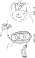
- Fig. 1A illustrates a non-limiting example of an electronic device 10, in this case an electric vehicle battery charging device 10 that has a power supply cord 12 terminated by a plug assembly 14.
- the electric vehicle battery charging device 10 is designed to operate from either a 110V/60 Hz AC or a 220V/60 Hz power source (not shown).
- Fig. 1B provides a close-up view of the plug assembly 14 of electric vehicle battery charging device 10 in one configuration, in this example adapted to connect with a NEMA 5-15R receptacle.
- Fig. 2 illustrates a non-limiting example of a plug housing 16 of the plug assembly 14.
- the plug housing 16 is designed to be attached to the end of a power supply cord 12 containing a ground wire and a pair of power wires (not shown).
- the plug housing 16 may define a flexible strain relief device (not shown) that surrounds the end of the power supply cord 12 and provides protection against wire breakage due to localized flexing of the wires.
- the plug housing 16 is formed of a dielectric material, e.g. polyvinyl chloride (PVC).
- PVC polyvinyl chloride
- the power and ground terminals 18, 20, 22 may be secured within the plug housing 16 by molding the plug housing 16 around the terminals 18, 20, 22 using an inert molding process. Alternatively, the terminals 18, 20, 22 may be held in place by mounting features within a cavity (not shown) inside the plug housing 16.
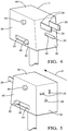
- Figs. 4 and 5 illustrate a non-limiting example of an enclosure 44 that is slideably attached to the plug housing 16.
- the enclosure 44 generally defines an open rectangular box shape having a top wall 46 , two opposed side walls 48 and two opposed end walls 50, 52 and open bottom.
- the enclosure 44 defines a cavity (not shown) in which the plug housing 16 is received.
- the two opposed side walls 48 each define linear slots 54 extending therethrough in which the pivot posts 40 are received, thereby slideably attaching the enclosure 44 to the plug housing 16.
- the linear slots 54 run substantially perpendicular to the end walls 50, 52.
- a first end wall 50 defines a first set of apertures 56 corresponding to the sizes and locations of the first power pins 24, 26 and the first ground pin 28 through which these pins 24, 26, 28 may protrude.
- a second end wall 52 of the enclosure 44 opposite the first end wall 50 defines a second set of apertures 58 corresponding to the sizes and locations of the second power and ground pins 32, 34, 36 through which these pins 32, 34, 36 may protrude.
- the length of the top and side walls 46, 48 is configured so that the first power and ground pins 24, 26, 28 are at least partially enclosed within the enclosure 44 when the second power and ground pins 32, 34, 36 protrude from the second set of apertures 58 and the second power and ground pins 32, 34, 36 are at least partially enclosed within the enclosure 44 when the first power and ground pins 24, 26, 28 protrude from the first set of apertures 56.
- the enclosure 44 is moveable from a first location 60 to a second location 62 by sliding the enclosure 44 in a first direction A.
- the first power and ground pins 24, 26, 28 fully protrude from the first set of apertures 56 (see Fig. 4 ) and the second power and ground pins 32, 34, 36 are fully enclosed within the enclosure 44 (see Fig. 5 ) inhibiting inadvertent contact with an energized second power pin 32, 34 when the first power pins 24, 26 are mated to a power receptacle.
- the second power and ground pins 32, 34, 36 fully protrude from the second set of apertures 58 (See Fig. 6 ) and the first power and ground pins 24, 26, 28 are fully enclosed within the enclosure 44 (see Fig. 7 ) inhibiting inadvertent contact with an energized first power pin 24, 26 when the second power pins 32, 34 are mated to a power receptacle.
- the enclosure 44 is further guided by the engagement of the first power and ground pins 24, 26, 28 with the first set of apertures 56 and/or second power and ground pins 32, 34, 36 with the second set of apertures 58.
- the enclosure 44 is returned moveable to the first location 60 from the second location 62 in by sliding the enclosure 44 in a second direction B.
- the top wall 70 of the hood 68 covers and encloses the second of apertures 58 further inhibiting inadvertent contact with an energized second power pin 32, 34 when the first power pins 24, 26 are mated to a power receptacle (not shown).
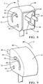
- hood 68 is rotated from the first position 76 to the second position 78 shown in Fig. 10 by rotating the hood 68 in the direction C.
- the slide posts 64 and the slider slots 66 cooperate to push the enclosure 44 from the first location 60 to the second location 62.
- the top wall 70 of the hood 68 covers and encloses the first set of apertures 56 when in the second position 78 further inhibiting inadvertent contact with an energized first power pin 24, 26 when the second power pins 32, 34 are mated to a power receptacle.
- the hood 68 is returned to the first position 76 by rotating the hood 68 in the direction D, thus moving the enclosure 44 to back the first location 60.
- the arcuate slider slots 66 allow the hood 68 to rotate and partially cover one end of each of the terminals 18, 20, 22 e.g. first power and ground pins 24, 26, 28, before the hood 68 starts sliding the enclosure 44, e.g. from the first position 76 to the second position 78.
- the hood 68 is configured to at least partially enclose one end of each of the terminals 18, 20, 22, e.g. first power and ground pins 24, 26, 28, before moving the enclosure 44 to expose the other end of the terminals, e.g. second power and ground pins 32, 34, 36. This feature prevents the plug assembly 14 from being plugged in to a power receptacle while enclosure 44 is moved between positions and reduces the likelihood of inadvertent contact with an energized power pin, e.g. the second power pins 32, 34.
- the configuration, i.e. pin length height, thickness and relative location, of the first power and ground pins 24, 26, 28 conform to a first technical specification, particularly a NEMA 6-20P standard used with 220V/60 Hz AC power in North America and the configuration of the second power and ground pins 32, 34, 36 conform to a second technical specification distinct from the first technical specification, particularly a NEMA 5-15P standard used with 110V/60 Hz AC power in North America.
- an electric vehicle battery charging device 10 with a power supply cord 12 having an adaptable electrical plug assembly 14 is provided.
- a single power supply cord 12 terminated by a plug assembly 14 may be used to supply either 110V or 220V AC power to the electric vehicle battery charging device 10.
- the plug assembly 14 provides the benefit of being compatible with power receptacles conforming to two different technical standards, e.g. a NEMA 5-15R and a NEMA 6-20R receptacle, without the need for a separate adapter.
- the plug assembly 14 may be more flush to a receptacle in which it is mated than a plug using a separate adapter.
- the plug adapter further provides the benefit of protecting the unmated pins within an enclosure 44 behind the hood 68.
Landscapes
- Engineering & Computer Science (AREA)
- Power Engineering (AREA)
- Transportation (AREA)
- Mechanical Engineering (AREA)
- Details Of Connecting Devices For Male And Female Coupling (AREA)
- Charge And Discharge Circuits For Batteries Or The Like (AREA)
- Connector Housings Or Holding Contact Members (AREA)
Abstract
Description
- The invention relates to an electrical plug assembly, particularly an electrical plug assembly adaptable to mate with various receptacles conforming to different receptacle configuration standards.
- National technical standards exist to define the physical and electrical characteristics of electrical plugs and their associated receptacles. The intent of these technical standards is to promote safety and operability between power sources and electronic devices that require electrical power. Historically, a particular electronic device would be designed for a specific source voltage and maximum current source and so would be manufactured with a fixed plug that is configured to insert into its complementary power-source receptacle. For example, an electronic device in North America requiring 220 volts and drawing a maximum current of 15 amperes would be supplied with a plug meeting the National Electrical Manufacturers Association (NEMA) 6-20 standard configured for insertion into a receptacle also conforming to the NEMA 6-20 standard. However, the NEMA 6-20 plug cannot be inserted into a receptacle capable of providing a lower 110 volt source voltage, such as a NEMA 5-15 standard receptacle.
- However, electronic devices are currently being manufactured that have built-in power electronics capable of converting various input voltages into an appropriate electrical power for the device. While an electronic device might be configured with a NEMA 6-20 plug for use with a 220V supply, it may be also operable with 110V power provided by a NEMA 5-15 receptacle
- Current solutions have involved the inclusion of a common plug to the electronic device and the use of two different power supply cords. A first cord has a common receptacle that is designed to mate with the plug in the electronic device on one end of the cord and a NEMA 6-20 plug the other. The second cord has the common receptacle on one end and a NEMA 5-15 plug on the other. This solution requires the addition of the common receptacle to the electronic device as well as a second power supply cord, adding additional cost to the device. A lower cost solution remains to be desired.
- The subject matter discussed in the background section should not be assumed to be prior art merely as a result of its mention in the background section. Similarly, a problem mentioned in the background section or associated with the subject matter of the background section should not be assumed to have been previously recognized in the prior art. The subject matter in the background section merely represents different approaches, which in and of themselves may also be inventions.
- In accordance with one embodiment of the invention, an electrical plug assembly is provided. The electrical plug assembly includes a plug housing that further includes a plurality of conductive first pins projecting from a first surface of the plug housing and a plurality of conductive second pins projecting from a second surface of the plug housing opposed to the first surface. The electrical plug assembly also includes an enclosure that is slideably attached to the plug housing. The enclosure defines a first plurality of apertures though which the plurality of first pins may protrude and a second plurality of apertures though which the plurality of second pins may protrude. The plurality of first pins are at least partially enclosed within the enclosure when the plurality of second pins protrude from the second plurality of apertures and the plurality of second pins are at least partially enclosed within the enclosure when the plurality of first pins protrude from the first plurality of apertures.
- The electrical plug assembly may further include a hood that is pivotally attached to the plug housing and that is slideably attached to the enclosure. The enclosure is rotatable from a first position to a second position. The hood is configured to urge the enclosure from a first location to a second location. The plurality of first pins are fully enclosed within the enclosure and the plurality of second pins protrude from the second plurality of apertures when the enclosure is in the first location. The plurality of second pins are completely enclosed within the enclosure and the plurality of first pins protrude from the first plurality of apertures when the enclosure is in the second location. The enclosure is in the first location when the hood is in the first position and the enclosure is in the second location when the hood is in the second position. The hood encloses the first plurality of apertures when in the first position and encloses the second plurality of apertures when in the second position.
- A configuration of the plurality of first pins may conform to a first technical specification and a configuration of the plurality of second pins conform to a second technical specification distinct from the first technical specification. The configuration of the plurality of first pins may conform to a National Electrical Manufacturers Association (NEMA) 5-15P standard and the configuration of the plurality of second pins may conform to a NEMA 6-20P standard.
- An electrical power cord assembly may include an electrical power cord and the electrical plug assembly described above. An electric vehicle battery charging assembly, may include an electric vehicle battery charging device capable of receiving electrical power having various source voltages the electrical power cord assembly described above.
- In accordance with another embodiment of the invention, an electrical plug assembly that is reconfigurable to mate with two different electrical receptacles conforming to different technical specifications is provided. The electrical plug assembly includes a plurality of conductive electrical terminals, each defining a conductive first pin and a conductive second pin. The electrical plug assembly also includes a plug housing in which the plurality of electrical terminals are disposed. The plug housing has a first end surface from which the plurality of first pins project and a second end surface opposed to the first end surface from which the plurality of second pins project. The plug housing defines pivot posts projecting from each of two opposed side surfaces. The electrical plug assembly further includes an enclosure having two opposed side walls, two opposed end walls and a top wall defining cavity in which the plug housing is received. The two opposed side walls each define slide posts projecting from the side walls and also define linear slots in which the pivot posts are received thereby slideably attaching the enclosure to the plug housing. A first end wall of the two opposed end walls defines a first plurality of apertures though which the plurality of first pins may protrude. A second end wall of the two opposed end walls defines a second plurality of apertures though which the plurality of second pins may protrude. The plurality of first pins are at least partially enclosed within the enclosure when the plurality of second pins protrude from the second plurality of apertures and the plurality of second pins are at least partially enclosed within the enclosure when the plurality of first pins protrude from the first plurality of apertures.
- The electrical plug assembly may further include a hood having an arcuate top wall and two generally sector shaped side walls. Each of the side walls defines arcuate slots and pivot apertures. The pivot posts of the plug housing are received within the pivot apertures thereby pivotally attaching the hood to the plug housing. The slide posts of the enclosure are received within the arcuate slots thereby slideably attaching the hood to the enclosure and limiting rotation of the hood about the pivot posts from a first position to a second position. The slide posts and the arcuate slots cooperate to urge the enclosure from a first location to a second location as the hood is rotated about the pivot posts.
- The plurality of first pins are fully enclosed within the enclosure and the plurality of second pins protrude from the second plurality of apertures when the enclosure is in the first location and the plurality of second pins are completely enclosed within the enclosure and the plurality of first pins protrude from the first plurality of apertures when the enclosure is in the second location. The enclosure is in the first location when the hood is in the first position and the enclosure is in the second location when the hood is in the second position. The hood encloses the first plurality of apertures when in the first position and the hood encloses the second plurality of apertures when in the second position.
- A configuration of the plurality of first pins may conform to a first technical specification and a configuration of the plurality of second pins may conform to a second technical specification distinct from the first technical specification. The configuration of the plurality of first pins may conform to a National Electrical Manufacturers Association (NEMA) 5-15P standard while the configuration of the plurality of second pins conform to a NEMA 6-20P standard.
- An electrical power cord assembly may include an electrical power cord and the electrical plug assembly described above. An electric vehicle battery charging assembly, may include an electric vehicle battery charging device capable of receiving electrical power having various source voltages the electrical power cord assembly described above.
- The present invention will now be described, by way of example with reference to the accompanying drawings, in which:
-
Fig. 1A is a perspective view of an electric vehicle battery charging device having a power cord terminated by an electrical plug assembly according to one embodiment; -
Fig. 1B is a close-up perspective view of the electrical plug assembly of the electric vehicle battery charging device ofFig. 1A according to one embodiment; -
Fig. 2 is a perspective front view of plug housing of an electrical plug assembly according to one embodiment; -
Fig 3 is a perspective front view of double ended terminals within the plug housing ofFig. 2 according to one embodiment; -
Fig. 4 is a perspective front view of an enclosure covering the plug housing ofFig. 2 in a first location showing a first plurality of terminal pins protruding through a first end wall of the enclosure according to one embodiment; -
Fig. 5 is a perspective rear view of an enclosure in the first location ofFig. 4 enclosing a second plurality of terminal pins behind a second end wall opposite the first end wall of the enclosure according to one embodiment; -
Fig. 6 is a perspective front view of the enclosure in a second location showing the second plurality of terminal pins protruding through the second end wall of the enclosure according to one embodiment; -
Fig. 7 is a perspective rear view of the enclosure in the second location ofFig. 6 enclosing the first plurality of terminal pins behind the first end wall of the enclosure according to one embodiment; -
Fig. 8 is a perspective front view of a hood pivotally attached to the plug housing and slideably attached to the enclosure in a first position according to one embodiment; -
Fig. 9 is a perspective rear view of the hood in the first position according to one embodiment; and -
Fig. 10 is a perspective front view of the hood in a second position according to one embodiment. - An adaptable electrical plug assembly, hereinafter referred to as the plug assembly, is presented herein. The plug assembly terminates one end of a power supply cord attached to an electrical device, such as electric vehicle battery charging device, capable of receiving electrical power having various source voltages. The plug assembly includes a plug housing having two sets terminal pins projecting from opposite faces of the plug housing. One set of terminal pins are configured to interface with a power supply receptacle conforming to a first technical standard and the second set of terminal pins are configured to interface with a power supply receptacle conforming to a second technical standard.
- As used herein, a "technical standard" is a formalized public document that defines a uniform physical and/or electrical configuration for a product, whether promulgated by a standards body, a regulatory body, or as a "de facto" standard set by widespread adoption. Technical standards include the standards established by the National Electrical Manufacturers Association ("NEMA") in the United States for use with alternating current (AC) electrical power connections, including but not limited to NEMA 5-15, NEMA 6-15, NEMA 5-20, and NEMA 6-20. Although a particular standard may have sub sections defining a receptacle configuration and plug configuration (and so designated with 'R' or 'P'), the description herein treats "a technical standard" as encompassing both receptacle and plug configurations in the same technical standard. The technical standards may also include standards defining electrical plugs and receptacles from outside of the United States.
- The plug assembly includes an enclosure that is slideably attached to the plug housing. When the enclosure is in a first location relative to the plug housing, the first set of terminal pins protrude though a corresponding set of apertures in the enclosure so that they may be inserted into a corresponding receptacle and the second set of terminal pins are completely contained within the enclosure, protecting them from inadvertent contact. When the enclosure is slid to a second location, the second set of terminal pins protrude though another corresponding set of apertures in the enclosure and the first set of terminal pins are contained within the enclosure.
- The plug assembly further includes a hood that is pivotally attached to the plug housing and slideably attached to the enclosure. As the enclosure is rotated about a pivot post on the plug housing from a first position to a second position, the hood slides the enclosure from the first location to the second location, pushing the second set of terminal pins through the corresponding apertures and withdrawing the first set of terminal pins within the enclosure. The hood further covers the apertures for the first set of terminal pins. As the enclosure is rotated about a pivot post on the plug housing from the second position back to the first position, the hood slides the enclosure from the second location to the first location, pushing the first set of terminal pins through the corresponding apertures and withdrawing the second set of terminal pins within the enclosure. In the second position, the hood covers the apertures for the second set of terminal pins.
- Thus, by rotating the hood between a first and second position, the plug assembly can be configured or adapted to plug into one of two different receptacles conforming to different technical specification.
-
Fig. 1A illustrates a non-limiting example of anelectronic device 10, in this case an electric vehiclebattery charging device 10 that has apower supply cord 12 terminated by aplug assembly 14. The electric vehiclebattery charging device 10 is designed to operate from either a 110V/60 Hz AC or a 220V/60 Hz power source (not shown).Fig. 1B provides a close-up view of theplug assembly 14 of electric vehiclebattery charging device 10 in one configuration, in this example adapted to connect with a NEMA 5-15R receptacle. -
Fig. 2 illustrates a non-limiting example of aplug housing 16 of theplug assembly 14. Theplug housing 16 is designed to be attached to the end of apower supply cord 12 containing a ground wire and a pair of power wires (not shown). Theplug housing 16 may define a flexible strain relief device (not shown) that surrounds the end of thepower supply cord 12 and provides protection against wire breakage due to localized flexing of the wires. Theplug housing 16 is formed of a dielectric material, e.g. polyvinyl chloride (PVC). - The
plug housing 16 contains a set of double endedterminals Fig. 3 . Oneend terminals first surface 30 of theplug housing 16 and theother end terminals second surface 38 of theplug housing 16 opposite thefirst surface 30.Power terminals second power pin 32. The major surfaces of the sides of the otherfirst power pin 26 are substantially perpendicular to the major surfaces of the sides of the othersecond power pin 34. As used herein, substantially parallel is ± 5° of absolutely parallel and substantially perpendicular is ± 5° of absolutely perpendicular. Theground terminal 22 has afirst ground pin 28 and asecond ground pin 36 having a generally round cross section. The width, thickness, length and position of the first power and ground pins 24, 26, 28 meet NEMA 5-15P standards. The width, thickness, length and position of the second power and ground pins 32, 34, 36 meet NEMA 6-20P standards. The power andground terminals ground terminals plug housing 16 by molding theplug housing 16 around theterminals terminals plug housing 16. - The
plug housing 16 further defines a pair of pivot posts 40 projecting from side surfaces 42 of theplug housing 16 adjacent the first andsecond surfaces plug housing 16. The pivot posts 40 have a generally cylindrical shape and project substantially perpendicularly from the side surfaces 42. - The
plug housing 16 may also include a thermistor (not shown) to detect a temperature of theplug assembly 14. Theelectrical device 10 connected to theplug assembly 14 may be designed to take countermeasures to reduce theplug assembly 14 temperature if it exceeds a temperature threshold. -
Figs. 4 and 5 illustrate a non-limiting example of anenclosure 44 that is slideably attached to theplug housing 16. Theenclosure 44 generally defines an open rectangular box shape having atop wall 46 , twoopposed side walls 48 and twoopposed end walls enclosure 44 defines a cavity (not shown) in which theplug housing 16 is received. The twoopposed side walls 48 each definelinear slots 54 extending therethrough in which the pivot posts 40 are received, thereby slideably attaching theenclosure 44 to theplug housing 16. Thelinear slots 54 run substantially perpendicular to theend walls Fig. 4 , afirst end wall 50 defines a first set ofapertures 56 corresponding to the sizes and locations of the first power pins 24, 26 and thefirst ground pin 28 through which thesepins Fig. 5 , asecond end wall 52 of theenclosure 44 opposite thefirst end wall 50 defines a second set ofapertures 58 corresponding to the sizes and locations of the second power and ground pins 32, 34, 36 through which thesepins - The length of the top and
side walls enclosure 44 when the second power and ground pins 32, 34, 36 protrude from the second set ofapertures 58 and the second power and ground pins 32, 34, 36 are at least partially enclosed within theenclosure 44 when the first power and ground pins 24, 26, 28 protrude from the first set ofapertures 56. - As illustrated in
Figs. 4-7 , by sliding thepivot post 40 along thelinear slot 54, theenclosure 44 is moveable from afirst location 60 to asecond location 62 by sliding theenclosure 44 in a first direction A. In thefirst location 60, the first power and ground pins 24, 26, 28 fully protrude from the first set of apertures 56 (seeFig. 4 ) and the second power and ground pins 32, 34, 36 are fully enclosed within the enclosure 44 (seeFig. 5 ) inhibiting inadvertent contact with an energizedsecond power pin second location 62, the second power and ground pins 32, 34, 36 fully protrude from the second set of apertures 58 (SeeFig. 6 ) and the first power and ground pins 24, 26, 28 are fully enclosed within the enclosure 44 (seeFig. 7 ) inhibiting inadvertent contact with an energizedfirst power pin enclosure 44 is further guided by the engagement of the first power and ground pins 24, 26, 28 with the first set ofapertures 56 and/or second power and ground pins 32, 34, 36 with the second set ofapertures 58. Theenclosure 44 is returned moveable to thefirst location 60 from thesecond location 62 in by sliding theenclosure 44 in a second direction B. - Each
outer side wall 48 of theenclosure 44 also defines aslide post 64 projecting outwardly from theside wall 48. The slide posts 64 preferably have a generally cylindrical shape and project substantially perpendicularly from theside walls 48, however other slide post shapes, such as square or rectangular may be suitable. The slide posts 64 are received inslider slots 66 in ahood 68 attached to both theplug housing 16 and theenclosure 44. -
Figs. 8 and 9 illustrate thehood 68 of theplug assembly 14. Thehood 68 has an arcuatetop wall 70 and two generally sector shapedside walls 72. Each of theside walls 72 of thehood 68 definearcuate slider slots 66 andpivot apertures 74. The pivot posts 40 of theplug housing 16 are received within thepivot apertures 74 thereby pivotally attaching thehood 68 to theplug housing 16. The slide posts 64 of theenclosure 44 are received within theslider slots 66 thereby slideably attaching thehood 68 to theenclosure 44. Theslider slots 66 limit rotation of thehood 68 about the pivot posts 40 from afirst position 76 to asecond position 78. When in thefirst position 76 shown inFigs. 8 and 9 , thetop wall 70 of thehood 68 covers and encloses the second ofapertures 58 further inhibiting inadvertent contact with an energizedsecond power pin - As the
hood 68 is rotated from thefirst position 76 to thesecond position 78 shown inFig. 10 by rotating thehood 68 in the direction C. The slide posts 64 and theslider slots 66 cooperate to push theenclosure 44 from thefirst location 60 to thesecond location 62. Thetop wall 70 of thehood 68 covers and encloses the first set ofapertures 56 when in thesecond position 78 further inhibiting inadvertent contact with an energizedfirst power pin hood 68 is returned to thefirst position 76 by rotating thehood 68 in the direction D, thus moving theenclosure 44 to back thefirst location 60. Thearcuate slider slots 66 allow thehood 68 to rotate and partially cover one end of each of theterminals hood 68 starts sliding theenclosure 44, e.g. from thefirst position 76 to thesecond position 78. Thehood 68 is configured to at least partially enclose one end of each of theterminals enclosure 44 to expose the other end of the terminals, e.g. second power and ground pins 32, 34, 36. This feature prevents theplug assembly 14 from being plugged in to a power receptacle whileenclosure 44 is moved between positions and reduces the likelihood of inadvertent contact with an energized power pin, e.g. the second power pins 32, 34. - As illustrated herein, the configuration, i.e. pin length height, thickness and relative location, of the first power and ground pins 24, 26, 28 conform to a first technical specification, particularly a NEMA 6-20P standard used with 220V/60 Hz AC power in North America and the configuration of the second power and ground pins 32, 34, 36 conform to a second technical specification distinct from the first technical specification, particularly a NEMA 5-15P standard used with 110V/60 Hz AC power in North America.
- Accordingly, an electric vehicle
battery charging device 10 with apower supply cord 12 having an adaptableelectrical plug assembly 14 is provided. Thus a singlepower supply cord 12 terminated by aplug assembly 14 may be used to supply either 110V or 220V AC power to the electric vehiclebattery charging device 10. Theplug assembly 14 provides the benefit of being compatible with power receptacles conforming to two different technical standards, e.g. a NEMA 5-15R and a NEMA 6-20R receptacle, without the need for a separate adapter. Theplug assembly 14 may be more flush to a receptacle in which it is mated than a plug using a separate adapter. The plug adapter further provides the benefit of protecting the unmated pins within anenclosure 44 behind thehood 68. - While the illustrated examples contained herein show a
plug assembly 14 that is adaptable between NEMA 5-15P and NEMA 6-20P technical standards used primarily in North America, other embodiments may be envisioned where the power and ground pins conform to other technical standards used in different parts of the world. - While this invention has been described in terms of the preferred embodiments thereof, it is not intended to be so limited, but rather only to the extent set forth in the claims that follow. Moreover, the use of the terms first, second, etc. does not denote any order of importance, but rather the terms first, second, etc. are used to distinguish one element from another. Furthermore, the use of the terms a, an, etc. do not denote a limitation of quantity, but rather denote the presence of at least one of the referenced items.
Claims (11)
- Electrical plug assembly (14) having a plug housing (16), comprising:a plurality of conductive first pins (24, 26, 28) projecting from a first surface (30) of the plug housing (16),a plurality of conductive second pins (32, 34, 36) projecting from a second surface (38) of the plug housing (16) opposed to the first surface (30);an enclosure (44) slideably attached to the plug housing (16) and defining a first plurality of apertures (56) though which the plurality of first pins (24, 26, 28) may protrude and a second plurality of apertures (58) though which the plurality of second pins (32, 34, 36) may protrude, wherein the plurality of first pins (24, 26, 28) are at least partially enclosed within the enclosure (44) when the plurality of second pins (32, 34, 36) protrude from the second plurality of apertures (58) and the plurality of second pins (32, 34, 36) are at least partially enclosed within the enclosure (44) when the plurality of first pins (24, 26, 28) protrude from the first plurality of apertures (56); and characterized bya hood (68) pivotally attached to the plug housing (16) and slideably attached to the enclosure (44) and rotatable from a first position (76) to a second position (78), wherein the hood (68) is configured to urge the enclosure (44) from a first location (60) to a second location (62).
- Electrical plug assembly (14) according to claim 1, wherein the plurality of first pins (24, 26, 28) are fully enclosed within the enclosure (44) and the plurality of second pins (32, 34, 36) protrude from the second plurality of apertures (58) when the enclosure (44) is in the first location (60) and the plurality of second pins (32, 34, 36) are completely enclosed within the enclosure (44) and the plurality of first pins (24, 26, 28) protrude from the first plurality of apertures (56) when the enclosure (44) is in the second location (62).
- Electrical plug assembly (14) according to claim 1 or 2, wherein the enclosure (44) is in the first location (60) when the hood (68) is in the first position (76) and the enclosure (44) is in the second location (62) when the hood (68) is in the second position (78).
- Electrical plug assembly (14) according to any of the preceding claims, wherein the hood (68) encloses the first plurality of apertures (56) when in the first position (76) and the hood (68) encloses the second plurality of apertures (58) when in the second position (78).
- Electrical plug assembly (14) according to any of the preceding claims, wherein a configuration of the plurality of first pins (24, 26, 28) conform to a first technical specification and a configuration of the plurality of second pins (32, 34, 36) conform to a second technical specification distinct from the first technical specification.
- Electrical plug assembly (14) reconfigurable to mate with two different electrical receptacles conforming to different technical specifications, comprising:a plurality of conductive electrical terminals (18), each defining a conductive first pin and a conductive second pin;a plug housing (16) in which the plurality of electrical terminals (18) are disposed and having a first end surface from which the plurality of first pins (24, 26, 28) project and a second end surface opposed to the first end surface from which the plurality of second pins (32, 34, 36) project and defining pivot posts (40) projecting from the plug housing (16); and characterized byan enclosure (44) having two opposed side walls (48), two opposed end walls (50, 52) and a top wall (46) defining cavity in which the plug housing (16) is received, wherein said two opposed side walls (48) each define slide posts (64) projecting from the side walls (48) and linear slots (54) in which the pivot posts (40) are received, thereby slideably attaching the enclosure (44) to the plug housing (16), wherein a first end wall (50) of the two opposed end walls (50) defines a first plurality of apertures (56) though which the plurality of first pins (24, 26, 28) may protrude and a second end wall (52) of the two opposed end walls (50) defines a second plurality of apertures (58) though which the plurality of second pins (32, 34, 36) may protrude, and wherein the plurality of first pins (24, 26, 28) are at least partially enclosed within the enclosure (44) when the plurality of second pins (32, 34, 36) protrude from the second plurality of apertures (58) and the plurality of second pins (32, 34, 36) are at least partially enclosed within the enclosure (44) when the plurality of first pins (24, 26, 28) protrude from the first plurality of apertures (56).
- Electrical plug assembly (14) according to claim 6, further comprising a hood (68) having an arcuate top wall (70) and two generally sector shaped side walls (72), each defining arcuate slots and pivot apertures (74), said pivot posts (40) of the plug housing (16) are received within the pivot apertures (74) thereby pivotally attaching the hood (68) to the plug housing (16) and said slide posts (64) of the enclosure (44) are received within the arcuate slots thereby slideably attaching the hood (68) to the enclosure (44) and limiting rotation of the hood (68) about the pivot posts (40) from a first position (76) to a second position (78), wherein the slide posts (64) and the arcuate slots cooperate to urge the enclosure (44) from a first location (60) to a second location (62).
- Electrical plug assembly (14) according to claim 6 or 7, wherein the plurality of first pins (24, 26, 28) are fully enclosed within the enclosure (44) and the plurality of second pins (32) protrude from the second plurality of apertures (56) when the enclosure (44) is in the first location (60) and the plurality of second pins (32, 34, 36) are completely enclosed within the enclosure (44) and the plurality of first pins (24, 26, 28) protrude from the first plurality of apertures (56) when the enclosure (44) is in the second location (62).
- Electrical plug assembly (14) according to claims 6-8, wherein the enclosure (44) is in the first location (60) when the hood (68) is in the first position (76) and the enclosure (44) is in the second location (62) when the hood (68) is in the second position (78).
- Electrical plug assembly (14) according to claims 6-9, wherein the hood (68) encloses the second plurality of apertures (56) when in the first position (76) and the hood (68) encloses the first plurality of apertures (56) when in the second position (78).
- Electrical plug assembly (14) according to claims 6-9, wherein a configuration of the plurality of first pins (24, 26, 28) conform to a first technical specification and a configuration of the plurality of second pins (32, 34, 36) conform to a second technical specification distinct from the first technical specification.
Applications Claiming Priority (1)
| Application Number | Priority Date | Filing Date | Title |
|---|---|---|---|
| US14/932,261 US9472899B1 (en) | 2015-11-04 | 2015-11-04 | Adaptable electrical plug assembly |
Publications (2)
| Publication Number | Publication Date |
|---|---|
| EP3166187A1 true EP3166187A1 (en) | 2017-05-10 |
| EP3166187B1 EP3166187B1 (en) | 2018-07-18 |
Family
ID=57120692
Family Applications (1)
| Application Number | Title | Priority Date | Filing Date |
|---|---|---|---|
| EP16196315.2A Not-in-force EP3166187B1 (en) | 2015-11-04 | 2016-10-28 | Adaptable electrical plug assembly |
Country Status (2)
| Country | Link |
|---|---|
| US (1) | US9472899B1 (en) |
| EP (1) | EP3166187B1 (en) |
Families Citing this family (7)
| Publication number | Priority date | Publication date | Assignee | Title |
|---|---|---|---|---|
| KR102666374B1 (en) * | 2017-01-23 | 2024-05-17 | 삼성에스디아이 주식회사 | Manual Service Disconnect for Battery System |
| JP7269178B2 (en) * | 2017-11-30 | 2023-05-08 | パナソニックホールディングス株式会社 | Electric propulsion vehicle charging cable and power adapter attached to the electric propulsion vehicle charging cable |
| CN109167226B (en) * | 2018-08-24 | 2020-01-24 | 安徽信息工程学院 | Variable pin type aerial plug |
| US11506541B2 (en) | 2019-01-03 | 2022-11-22 | Aptiv Technologies Limited | Temperature monitoring device |
| CN112736602B (en) | 2019-10-14 | 2022-07-05 | Oppo广东移动通信有限公司 | Plug structure and electronic equipment |
| CN112290332B (en) * | 2020-10-31 | 2021-12-03 | 贵州电网有限责任公司 | Adapter |
| NO346426B1 (en) * | 2021-01-15 | 2022-08-08 | Defa As | A charger assembly |
Citations (2)
| Publication number | Priority date | Publication date | Assignee | Title |
|---|---|---|---|---|
| US4518212A (en) * | 1982-08-04 | 1985-05-21 | Corabelment A.G. | Multiple pin electrical plug |
| US6062884A (en) * | 1998-09-11 | 2000-05-16 | Hybrinetics, Inc. | Rotationally activated multiple plug receptacle adapter |
Family Cites Families (8)
| Publication number | Priority date | Publication date | Assignee | Title |
|---|---|---|---|---|
| US3034000A (en) * | 1960-07-19 | 1962-05-08 | Todd Electric Company Inc | Appliance adapter |
| US4585286A (en) * | 1985-08-05 | 1986-04-29 | Darrell Parr | Universal electrical plug adapter |
| KR950023326A (en) * | 1994-01-14 | 1995-08-18 | 이상수 | How to Make Watermelon Juice |
| US6669495B2 (en) | 2000-11-06 | 2003-12-30 | Research In Motion Limited | Universal adapter with interchangeable plugs |
| US6699052B1 (en) | 2002-10-10 | 2004-03-02 | Epilady 2000 L.L.C. | Dual voltage power converter |
| US7121850B2 (en) * | 2004-11-05 | 2006-10-17 | Ming-Hsiang Yeh | Dual-purpose male/female connector |
| US8951075B2 (en) | 2011-01-06 | 2015-02-10 | Jack A. Ekchian | Multi-piece electrical connector |
| CA2906202A1 (en) | 2013-03-15 | 2014-09-18 | Aerovironment, Inc. | Electrical plug adapter having socket key safety system |
-
2015
- 2015-11-04 US US14/932,261 patent/US9472899B1/en not_active Expired - Fee Related
-
2016
- 2016-10-28 EP EP16196315.2A patent/EP3166187B1/en not_active Not-in-force
Patent Citations (2)
| Publication number | Priority date | Publication date | Assignee | Title |
|---|---|---|---|---|
| US4518212A (en) * | 1982-08-04 | 1985-05-21 | Corabelment A.G. | Multiple pin electrical plug |
| US6062884A (en) * | 1998-09-11 | 2000-05-16 | Hybrinetics, Inc. | Rotationally activated multiple plug receptacle adapter |
Also Published As
| Publication number | Publication date |
|---|---|
| US9472899B1 (en) | 2016-10-18 |
| EP3166187B1 (en) | 2018-07-18 |
Similar Documents
| Publication | Publication Date | Title |
|---|---|---|
| EP3166187B1 (en) | Adaptable electrical plug assembly | |
| US9493083B1 (en) | Electrical plug adapter | |
| CN102439800B (en) | electric plug | |
| KR102241749B1 (en) | Connector | |
| US8834186B2 (en) | Power socket and safety gate mechanism thereof | |
| US7566223B2 (en) | Electrical connector and method of manufacturing same | |
| US9847591B2 (en) | Electric terminal assembly | |
| JP5791084B2 (en) | Interlock circuit connector assembly | |
| CN1096726C (en) | Plug adapter for rechargeable electrical devices | |
| EP3246198A1 (en) | Electric vehicle supply equipment with interchangeable power supply cords conforming to different technical standards | |
| CN112615216A (en) | Power connector system | |
| US9281638B2 (en) | Connectors | |
| EP3648259B1 (en) | Electrical connector with latches and terminal position assurance projections provided on hinged cover | |
| US11471018B2 (en) | Method of charging a rechargeable battery | |
| CA2906202A1 (en) | Electrical plug adapter having socket key safety system | |
| US10312622B2 (en) | Movable socket assembly | |
| CN107666093B (en) | Connector | |
| US7001194B2 (en) | Electric power connector and electric power connector assembly | |
| CN104009351A (en) | Universal international multi-functional environment-friendly extension power supply connecting device | |
| US11527856B2 (en) | Charger extension device | |
| CN214280358U (en) | Safety electric connector | |
| US9768554B2 (en) | Adaptable electrical plug assembly | |
| CN213401713U (en) | Electric connector male end, female end, electric connector and power supply or power consumption equipment | |
| CN104183956B (en) | Wiring board | |
| GB2381669A (en) | Folding plug |
Legal Events
| Date | Code | Title | Description |
|---|---|---|---|
| PUAI | Public reference made under article 153(3) epc to a published international application that has entered the european phase |
Free format text: ORIGINAL CODE: 0009012 |
|
| AK | Designated contracting states |
Kind code of ref document: A1 Designated state(s): AL AT BE BG CH CY CZ DE DK EE ES FI FR GB GR HR HU IE IS IT LI LT LU LV MC MK MT NL NO PL PT RO RS SE SI SK SM TR |
|
| AX | Request for extension of the european patent |
Extension state: BA ME |
|
| 17P | Request for examination filed |
Effective date: 20171110 |
|
| RBV | Designated contracting states (corrected) |
Designated state(s): AL AT BE BG CH CY CZ DE DK EE ES FI FR GB GR HR HU IE IS IT LI LT LU LV MC MK MT NL NO PL PT RO RS SE SI SK SM TR |
|
| GRAP | Despatch of communication of intention to grant a patent |
Free format text: ORIGINAL CODE: EPIDOSNIGR1 |
|
| RIC1 | Information provided on ipc code assigned before grant |
Ipc: B60L 11/18 20060101ALI20180129BHEP Ipc: H01R 13/516 20060101ALN20180129BHEP Ipc: H01R 13/447 20060101ALN20180129BHEP Ipc: H01R 24/30 20110101ALN20180129BHEP Ipc: H01R 27/00 20060101AFI20180129BHEP |
|
| INTG | Intention to grant announced |
Effective date: 20180214 |
|
| RIC1 | Information provided on ipc code assigned before grant |
Ipc: H01R 13/516 20060101ALN20180202BHEP Ipc: H01R 13/447 20060101ALN20180202BHEP Ipc: B60L 11/18 20060101ALI20180202BHEP Ipc: H01R 24/30 20110101ALN20180202BHEP Ipc: H01R 27/00 20060101AFI20180202BHEP |
|
| GRAS | Grant fee paid |
Free format text: ORIGINAL CODE: EPIDOSNIGR3 |
|
| GRAA | (expected) grant |
Free format text: ORIGINAL CODE: 0009210 |
|
| AK | Designated contracting states |
Kind code of ref document: B1 Designated state(s): AL AT BE BG CH CY CZ DE DK EE ES FI FR GB GR HR HU IE IS IT LI LT LU LV MC MK MT NL NO PL PT RO RS SE SI SK SM TR |
|
| REG | Reference to a national code |
Ref country code: GB Ref legal event code: FG4D |
|
| REG | Reference to a national code |
Ref country code: CH Ref legal event code: EP |
|
| REG | Reference to a national code |
Ref country code: IE Ref legal event code: FG4D |
|
| REG | Reference to a national code |
Ref country code: AT Ref legal event code: REF Ref document number: 1020372 Country of ref document: AT Kind code of ref document: T Effective date: 20180815 |
|
| REG | Reference to a national code |
Ref country code: DE Ref legal event code: R096 Ref document number: 602016004121 Country of ref document: DE |
|
| REG | Reference to a national code |
Ref country code: FR Ref legal event code: PLFP Year of fee payment: 3 |
|
| REG | Reference to a national code |
Ref country code: NL Ref legal event code: MP Effective date: 20180718 |
|
| REG | Reference to a national code |
Ref country code: DE Ref legal event code: R081 Ref document number: 602016004121 Country of ref document: DE Owner name: APTIV TECHNOLOGIES LIMITED, BB Free format text: FORMER OWNER: DELPHI TECHNOLOGIES, INC., TROY, MICH., US |
|
| REG | Reference to a national code |
Ref country code: LT Ref legal event code: MG4D |
|
| REG | Reference to a national code |
Ref country code: AT Ref legal event code: MK05 Ref document number: 1020372 Country of ref document: AT Kind code of ref document: T Effective date: 20180718 |
|
| PG25 | Lapsed in a contracting state [announced via postgrant information from national office to epo] |
Ref country code: NL Free format text: LAPSE BECAUSE OF FAILURE TO SUBMIT A TRANSLATION OF THE DESCRIPTION OR TO PAY THE FEE WITHIN THE PRESCRIBED TIME-LIMIT Effective date: 20180718 |
|
| PG25 | Lapsed in a contracting state [announced via postgrant information from national office to epo] |
Ref country code: NO Free format text: LAPSE BECAUSE OF FAILURE TO SUBMIT A TRANSLATION OF THE DESCRIPTION OR TO PAY THE FEE WITHIN THE PRESCRIBED TIME-LIMIT Effective date: 20181018 Ref country code: SE Free format text: LAPSE BECAUSE OF FAILURE TO SUBMIT A TRANSLATION OF THE DESCRIPTION OR TO PAY THE FEE WITHIN THE PRESCRIBED TIME-LIMIT Effective date: 20180718 Ref country code: GR Free format text: LAPSE BECAUSE OF FAILURE TO SUBMIT A TRANSLATION OF THE DESCRIPTION OR TO PAY THE FEE WITHIN THE PRESCRIBED TIME-LIMIT Effective date: 20181019 Ref country code: AT Free format text: LAPSE BECAUSE OF FAILURE TO SUBMIT A TRANSLATION OF THE DESCRIPTION OR TO PAY THE FEE WITHIN THE PRESCRIBED TIME-LIMIT Effective date: 20180718 Ref country code: PL Free format text: LAPSE BECAUSE OF FAILURE TO SUBMIT A TRANSLATION OF THE DESCRIPTION OR TO PAY THE FEE WITHIN THE PRESCRIBED TIME-LIMIT Effective date: 20180718 Ref country code: IS Free format text: LAPSE BECAUSE OF FAILURE TO SUBMIT A TRANSLATION OF THE DESCRIPTION OR TO PAY THE FEE WITHIN THE PRESCRIBED TIME-LIMIT Effective date: 20181118 Ref country code: LT Free format text: LAPSE BECAUSE OF FAILURE TO SUBMIT A TRANSLATION OF THE DESCRIPTION OR TO PAY THE FEE WITHIN THE PRESCRIBED TIME-LIMIT Effective date: 20180718 Ref country code: BG Free format text: LAPSE BECAUSE OF FAILURE TO SUBMIT A TRANSLATION OF THE DESCRIPTION OR TO PAY THE FEE WITHIN THE PRESCRIBED TIME-LIMIT Effective date: 20181018 Ref country code: RS Free format text: LAPSE BECAUSE OF FAILURE TO SUBMIT A TRANSLATION OF THE DESCRIPTION OR TO PAY THE FEE WITHIN THE PRESCRIBED TIME-LIMIT Effective date: 20180718 Ref country code: FI Free format text: LAPSE BECAUSE OF FAILURE TO SUBMIT A TRANSLATION OF THE DESCRIPTION OR TO PAY THE FEE WITHIN THE PRESCRIBED TIME-LIMIT Effective date: 20180718 |
|
| REG | Reference to a national code |
Ref country code: GB Ref legal event code: 732E Free format text: REGISTERED BETWEEN 20190117 AND 20190123 |
|
| REG | Reference to a national code |
Ref country code: GB Ref legal event code: 732E Free format text: REGISTERED BETWEEN 20190124 AND 20190130 |
|
| PG25 | Lapsed in a contracting state [announced via postgrant information from national office to epo] |
Ref country code: LV Free format text: LAPSE BECAUSE OF FAILURE TO SUBMIT A TRANSLATION OF THE DESCRIPTION OR TO PAY THE FEE WITHIN THE PRESCRIBED TIME-LIMIT Effective date: 20180718 Ref country code: AL Free format text: LAPSE BECAUSE OF FAILURE TO SUBMIT A TRANSLATION OF THE DESCRIPTION OR TO PAY THE FEE WITHIN THE PRESCRIBED TIME-LIMIT Effective date: 20180718 Ref country code: HR Free format text: LAPSE BECAUSE OF FAILURE TO SUBMIT A TRANSLATION OF THE DESCRIPTION OR TO PAY THE FEE WITHIN THE PRESCRIBED TIME-LIMIT Effective date: 20180718 |
|
| REG | Reference to a national code |
Ref country code: DE Ref legal event code: R097 Ref document number: 602016004121 Country of ref document: DE |
|
| PG25 | Lapsed in a contracting state [announced via postgrant information from national office to epo] |
Ref country code: EE Free format text: LAPSE BECAUSE OF FAILURE TO SUBMIT A TRANSLATION OF THE DESCRIPTION OR TO PAY THE FEE WITHIN THE PRESCRIBED TIME-LIMIT Effective date: 20180718 Ref country code: IT Free format text: LAPSE BECAUSE OF FAILURE TO SUBMIT A TRANSLATION OF THE DESCRIPTION OR TO PAY THE FEE WITHIN THE PRESCRIBED TIME-LIMIT Effective date: 20180718 Ref country code: ES Free format text: LAPSE BECAUSE OF FAILURE TO SUBMIT A TRANSLATION OF THE DESCRIPTION OR TO PAY THE FEE WITHIN THE PRESCRIBED TIME-LIMIT Effective date: 20180718 Ref country code: CZ Free format text: LAPSE BECAUSE OF FAILURE TO SUBMIT A TRANSLATION OF THE DESCRIPTION OR TO PAY THE FEE WITHIN THE PRESCRIBED TIME-LIMIT Effective date: 20180718 Ref country code: RO Free format text: LAPSE BECAUSE OF FAILURE TO SUBMIT A TRANSLATION OF THE DESCRIPTION OR TO PAY THE FEE WITHIN THE PRESCRIBED TIME-LIMIT Effective date: 20180718 |
|
| PLBE | No opposition filed within time limit |
Free format text: ORIGINAL CODE: 0009261 |
|
| STAA | Information on the status of an ep patent application or granted ep patent |
Free format text: STATUS: NO OPPOSITION FILED WITHIN TIME LIMIT |
|
| PG25 | Lapsed in a contracting state [announced via postgrant information from national office to epo] |
Ref country code: DK Free format text: LAPSE BECAUSE OF FAILURE TO SUBMIT A TRANSLATION OF THE DESCRIPTION OR TO PAY THE FEE WITHIN THE PRESCRIBED TIME-LIMIT Effective date: 20180718 Ref country code: SM Free format text: LAPSE BECAUSE OF FAILURE TO SUBMIT A TRANSLATION OF THE DESCRIPTION OR TO PAY THE FEE WITHIN THE PRESCRIBED TIME-LIMIT Effective date: 20180718 Ref country code: SK Free format text: LAPSE BECAUSE OF FAILURE TO SUBMIT A TRANSLATION OF THE DESCRIPTION OR TO PAY THE FEE WITHIN THE PRESCRIBED TIME-LIMIT Effective date: 20180718 |
|
| 26N | No opposition filed |
Effective date: 20190423 |
|
| REG | Reference to a national code |
Ref country code: BE Ref legal event code: MM Effective date: 20181031 |
|
| PG25 | Lapsed in a contracting state [announced via postgrant information from national office to epo] |
Ref country code: LU Free format text: LAPSE BECAUSE OF NON-PAYMENT OF DUE FEES Effective date: 20181028 Ref country code: MC Free format text: LAPSE BECAUSE OF FAILURE TO SUBMIT A TRANSLATION OF THE DESCRIPTION OR TO PAY THE FEE WITHIN THE PRESCRIBED TIME-LIMIT Effective date: 20180718 |
|
| REG | Reference to a national code |
Ref country code: IE Ref legal event code: MM4A |
|
| PG25 | Lapsed in a contracting state [announced via postgrant information from national office to epo] |
Ref country code: BE Free format text: LAPSE BECAUSE OF NON-PAYMENT OF DUE FEES Effective date: 20181031 Ref country code: SI Free format text: LAPSE BECAUSE OF FAILURE TO SUBMIT A TRANSLATION OF THE DESCRIPTION OR TO PAY THE FEE WITHIN THE PRESCRIBED TIME-LIMIT Effective date: 20180718 |
|
| PG25 | Lapsed in a contracting state [announced via postgrant information from national office to epo] |
Ref country code: IE Free format text: LAPSE BECAUSE OF NON-PAYMENT OF DUE FEES Effective date: 20181028 |
|
| PG25 | Lapsed in a contracting state [announced via postgrant information from national office to epo] |
Ref country code: MT Free format text: LAPSE BECAUSE OF NON-PAYMENT OF DUE FEES Effective date: 20181028 |
|
| PGFP | Annual fee paid to national office [announced via postgrant information from national office to epo] |
Ref country code: DE Payment date: 20191029 Year of fee payment: 4 |
|
| PGFP | Annual fee paid to national office [announced via postgrant information from national office to epo] |
Ref country code: FR Payment date: 20191025 Year of fee payment: 4 |
|
| PG25 | Lapsed in a contracting state [announced via postgrant information from national office to epo] |
Ref country code: TR Free format text: LAPSE BECAUSE OF FAILURE TO SUBMIT A TRANSLATION OF THE DESCRIPTION OR TO PAY THE FEE WITHIN THE PRESCRIBED TIME-LIMIT Effective date: 20180718 |
|
| PG25 | Lapsed in a contracting state [announced via postgrant information from national office to epo] |
Ref country code: PT Free format text: LAPSE BECAUSE OF FAILURE TO SUBMIT A TRANSLATION OF THE DESCRIPTION OR TO PAY THE FEE WITHIN THE PRESCRIBED TIME-LIMIT Effective date: 20180718 |
|
| REG | Reference to a national code |
Ref country code: CH Ref legal event code: PL |
|
| PG25 | Lapsed in a contracting state [announced via postgrant information from national office to epo] |
Ref country code: MK Free format text: LAPSE BECAUSE OF NON-PAYMENT OF DUE FEES Effective date: 20180718 Ref country code: CY Free format text: LAPSE BECAUSE OF FAILURE TO SUBMIT A TRANSLATION OF THE DESCRIPTION OR TO PAY THE FEE WITHIN THE PRESCRIBED TIME-LIMIT Effective date: 20180718 Ref country code: HU Free format text: LAPSE BECAUSE OF FAILURE TO SUBMIT A TRANSLATION OF THE DESCRIPTION OR TO PAY THE FEE WITHIN THE PRESCRIBED TIME-LIMIT; INVALID AB INITIO Effective date: 20161028 |
|
| PG25 | Lapsed in a contracting state [announced via postgrant information from national office to epo] |
Ref country code: CH Free format text: LAPSE BECAUSE OF NON-PAYMENT OF DUE FEES Effective date: 20191031 Ref country code: LI Free format text: LAPSE BECAUSE OF NON-PAYMENT OF DUE FEES Effective date: 20191031 |
|
| REG | Reference to a national code |
Ref country code: DE Ref legal event code: R119 Ref document number: 602016004121 Country of ref document: DE |
|
| GBPC | Gb: european patent ceased through non-payment of renewal fee |
Effective date: 20201028 |
|
| PG25 | Lapsed in a contracting state [announced via postgrant information from national office to epo] |
Ref country code: DE Free format text: LAPSE BECAUSE OF NON-PAYMENT OF DUE FEES Effective date: 20210501 Ref country code: FR Free format text: LAPSE BECAUSE OF NON-PAYMENT OF DUE FEES Effective date: 20201031 |
|
| PG25 | Lapsed in a contracting state [announced via postgrant information from national office to epo] |
Ref country code: GB Free format text: LAPSE BECAUSE OF NON-PAYMENT OF DUE FEES Effective date: 20201028 |