EP3166127A1 - Method for optimizing charged particle beams formed by shaped apertures - Google Patents
Method for optimizing charged particle beams formed by shaped apertures Download PDFInfo
- Publication number
- EP3166127A1 EP3166127A1 EP16196521.5A EP16196521A EP3166127A1 EP 3166127 A1 EP3166127 A1 EP 3166127A1 EP 16196521 A EP16196521 A EP 16196521A EP 3166127 A1 EP3166127 A1 EP 3166127A1
- Authority
- EP
- European Patent Office
- Prior art keywords
- aperture
- working
- work piece
- current
- ion
- Prior art date
- Legal status (The legal status is an assumption and is not a legal conclusion. Google has not performed a legal analysis and makes no representation as to the accuracy of the status listed.)
- Granted
Links
Images



Classifications
-
- H—ELECTRICITY
- H01—ELECTRIC ELEMENTS
- H01J—ELECTRIC DISCHARGE TUBES OR DISCHARGE LAMPS
- H01J37/00—Discharge tubes with provision for introducing objects or material to be exposed to the discharge, e.g. for the purpose of examination or processing thereof
- H01J37/30—Electron-beam or ion-beam tubes for localised treatment of objects
- H01J37/31—Electron-beam or ion-beam tubes for localised treatment of objects for cutting or drilling
-
- H—ELECTRICITY
- H01—ELECTRIC ELEMENTS
- H01J—ELECTRIC DISCHARGE TUBES OR DISCHARGE LAMPS
- H01J37/00—Discharge tubes with provision for introducing objects or material to be exposed to the discharge, e.g. for the purpose of examination or processing thereof
- H01J37/02—Details
- H01J37/21—Means for adjusting the focus
-
- H—ELECTRICITY
- H01—ELECTRIC ELEMENTS
- H01J—ELECTRIC DISCHARGE TUBES OR DISCHARGE LAMPS
- H01J37/00—Discharge tubes with provision for introducing objects or material to be exposed to the discharge, e.g. for the purpose of examination or processing thereof
- H01J37/26—Electron or ion microscopes; Electron or ion diffraction tubes
- H01J37/28—Electron or ion microscopes; Electron or ion diffraction tubes with scanning beams
-
- H—ELECTRICITY
- H01—ELECTRIC ELEMENTS
- H01J—ELECTRIC DISCHARGE TUBES OR DISCHARGE LAMPS
- H01J37/00—Discharge tubes with provision for introducing objects or material to be exposed to the discharge, e.g. for the purpose of examination or processing thereof
- H01J37/02—Details
- H01J37/04—Arrangements of electrodes and associated parts for generating or controlling the discharge, e.g. electron-optical arrangement or ion-optical arrangement
- H01J37/10—Lenses
-
- H—ELECTRICITY
- H01—ELECTRIC ELEMENTS
- H01J—ELECTRIC DISCHARGE TUBES OR DISCHARGE LAMPS
- H01J37/00—Discharge tubes with provision for introducing objects or material to be exposed to the discharge, e.g. for the purpose of examination or processing thereof
- H01J37/26—Electron or ion microscopes; Electron or ion diffraction tubes
-
- H—ELECTRICITY
- H01—ELECTRIC ELEMENTS
- H01J—ELECTRIC DISCHARGE TUBES OR DISCHARGE LAMPS
- H01J2237/00—Discharge tubes exposing object to beam, e.g. for analysis treatment, etching, imaging
- H01J2237/04—Means for controlling the discharge
- H01J2237/045—Diaphragms
- H01J2237/0451—Diaphragms with fixed aperture
- H01J2237/0453—Diaphragms with fixed aperture multiple apertures
-
- H—ELECTRICITY
- H01—ELECTRIC ELEMENTS
- H01J—ELECTRIC DISCHARGE TUBES OR DISCHARGE LAMPS
- H01J2237/00—Discharge tubes exposing object to beam, e.g. for analysis treatment, etching, imaging
- H01J2237/30—Electron or ion beam tubes for processing objects
- H01J2237/304—Controlling tubes
- H01J2237/30472—Controlling the beam
-
- H—ELECTRICITY
- H01—ELECTRIC ELEMENTS
- H01J—ELECTRIC DISCHARGE TUBES OR DISCHARGE LAMPS
- H01J2237/00—Discharge tubes exposing object to beam, e.g. for analysis treatment, etching, imaging
- H01J2237/30—Electron or ion beam tubes for processing objects
- H01J2237/317—Processing objects on a microscale
-
- H—ELECTRICITY
- H01—ELECTRIC ELEMENTS
- H01J—ELECTRIC DISCHARGE TUBES OR DISCHARGE LAMPS
- H01J2237/00—Discharge tubes exposing object to beam, e.g. for analysis treatment, etching, imaging
- H01J2237/30—Electron or ion beam tubes for processing objects
- H01J2237/317—Processing objects on a microscale
- H01J2237/3174—Etching microareas
- H01J2237/31745—Etching microareas for preparing specimen to be viewed in microscopes or analyzed in microanalysers
-
- H—ELECTRICITY
- H01—ELECTRIC ELEMENTS
- H01J—ELECTRIC DISCHARGE TUBES OR DISCHARGE LAMPS
- H01J2237/00—Discharge tubes exposing object to beam, e.g. for analysis treatment, etching, imaging
- H01J2237/30—Electron or ion beam tubes for processing objects
- H01J2237/317—Processing objects on a microscale
- H01J2237/31749—Focused ion beam
Definitions
- the present invention relates to a method of optimizing a shaped beam, such as an electron beam, ion beam, or laser beam, for precision milling applications.
- Charged particle beams, laser beams, and neutral particle beams are used in a variety of microfabrication applications, such as fabrication of semiconductor circuitry and microelectromechanical assemblies.
- microfabrication is used to include creating and altering structures having dimensions of tens of microns or less, including nanofabrication processes.
- Processing a sample refers to the microfabrication of structures on that sample.
- charged particle beam systems such as electron microscopes or focused ion beam (FIB) systems
- a source In charged particle beam systems, such as electron microscopes or focused ion beam (FIB) systems, a source generates charged particles which are then focused by an optical column into a beam and directed onto the surface of a target to be imaged and/or processed. In the column, this beam may be deflected to move it around on the target surface. As smaller and smaller structures are fabricated, it is necessary to direct the beam more precisely.
- FIB focused ion beam
- TEM transmission electron microscope
- a beam controller directs the beam to specified coordinates or along a specified path using a beam controller coordinate system in response to a stored program, pattern generator, or operator instructions to perform a specific process.
- the beam converges in the plane of the work piece or target specimen.
- the beam may converge before or after the sample plane causing the beam to be unfocussed.
- the beam may exhibit stigmatic effects.
- there may be rotational misalignment between the axis of the specimen and the scan axis of the beam.
- the scan gain may be different in each of the orthogonal scan directions so that in one direction the image appears "stretched".
- the scanned beam system must therefore be calibrated to eliminate or at least minimize these errors.
- a beam system will typically provide control elements to achieve calibration.
- an electrostatic lens system may be provided to cause the beam to converge at the correct focal point and a stigmator may be provided to adjust for stigmation effects.
- the milling rate is roughly proportional to the beam current. For precision processing in which a charged particle beam is used to mill material from the surface of a target the milling rate is roughly proportional to the beam current. For example, higher beam currents are preferred when it is desired to quickly remove material. However, beams using higher current are less precise and typically result in a damaged or undesirable sample. Therefore, lower beam currents have been used for more precision processing applications.
- a beam having a lower beam current that is, fewer charged particles per second, can typically be focused to a smaller size than a beam having a higher current. For example, a small beam with a lower current is more precise and results in less unwanted damage to the sample. See, for example, U.S. Pat. No.
- Non-round or "shaped" beams have been developed in order to increase milling speed. Shaped beams can be generated having a straight edge for cutting away material, and at the same time, having their beam spot shapes of a size with enough beam current for quickly removing material. See, for example, U.S. Pat. No. 6,977,386 , entitled “Angular Aperture Shaped Beam System And Method” to Gerlach et al., assigned to the assignee of the present invention, which is hereby incorporated by reference.
- the beam is shaped by an aperture plate positioned within the optical column having one or more selectable beam-defining apertures (BDAs) through which the beam passes.
- BDAs are typically holes in a metal strip, which are intended to block the off-axis charged particles and to pass the ones used to form the beam.
- a beam having a desired geometrically shaped spot is formed by a shaping aperture typically disposed between one or more lenses in a charged particle column.
- control elements may include a two-lens focusing column in which the first lens forms an image of the beam at or near the plane of the second lens and the second lens forms an image of the shaping aperture on the target plane.
- the lenses and other "optical" elements (i.e., a stigmator) in the beam column may use electrostatic or magnetic fields to align the beam along the optical axis and focus the beam on the target plane.
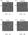
- FIGS. 1A and 1B show spot burn arrays for a 130 pA round beam.
- FIG. 1A shows a spot burn array 100 where the second lens focus was varied in a serpentine fashion from top to bottom and left to right. The beam was optimized using an image sharpness routine based on auto focus so that the center spot 102 is near optimal.
- FIG. 1B shows a spot burn array 104 where the stigmation was varied along X and Y directions. The beam was optimized using an image sharpness routine based on stigmation so that the center spot 106 is near optimal.
- FIG. 2A shows a spot burn array 108 where the second lens focus was varied in a serpentine fashion from top to bottom and from left to right. The beam was optimized using an image sharpness routine based on auto focus on its corresponding round beam so that the center spot 110 is near optimal.
- FIG. 2B shows a spot burn array 112 where the stigmation was varied along X and Y directions. The beam was optimized using an image sharpness routine based on stigmation on its corresponding round beam so that the center spot 114 is near optimal.
- the optimal spots 110, 114 are not elliptical but are more flat. This is because the auto focus/stigmation routines applied to elliptical beams (or other shaped beams) will typically seek out the roundest beam. However, the roundest-shaped elliptical beam is sub-optimal for milling.
- What is needed is a method and system for optimizing a shaped beam having a sharp edge to achieve clean and fine milling operations while having a high current for rapid processing.
- the present invention provides a method for optimizing a shaped beam having a sharp edge for making sufficiently precise cuts and a high beam current for faster processing.
- An ion beam is directed along an optical column through a reference aperture to form a reference beam that has a preferred shape and an associated reference current.
- the reference beam is aligned with the axis of the optical column and focused onto a target plane using selected parameters of the optical components within the optical column so that the reference beam has a profile with a sharp edge.
- the ion beam is then directed through a working aperture to form a working beam for use in a processing application.
- the working beam has a different shape from the reference beam and an associated working current that is higher than the reference current.
- the working beam is aligned with the axis of the optical column and focused onto the target plane using the selected optical component parameters used to align and focus the reference beam.
- This produces a working beam that has a profile with at least one sharp edge that substantially corresponds to the sharp edge produced by the reference beam but has a higher current.
- the reference aperture and working aperture have at least one corresponding dimension that produces the sharp edge.
- the reference aperture is round and has a diameter that extends along an axis.
- the working aperture has a shape with a minor diameter, such as an ellipse, that extends along an axis with the same alignment as the reference aperture axis.
- the diameter of the reference aperture is substantially similar to the minor diameter of the working aperture to produce a working beam that has a sharp edge corresponding to the sharp edge of the reference beam but the shape of the working aperture produces a beam with a higher current.
- an ion optical column in a focused ion beam system produces a shaped beam having one or more geometric features having a sharp resolution that is focused and aligned with the axis of the optical column.
- Microstructure milling tasks such as cross-sectional cutting for imaging, for example, require beams with at least one sharp edge for cutting away a slice that leaves a straight, "clean" cross-sectional surface.
- the beam spot has a leading edge, which is a sharp edge of the spot that can be used to mill away sharp, vertical faces.
- the beam spot also has width and depth dimensions. Some applications may require a beam having a minimized depth or width to produce a sharp edge with a high current for faster milling.
- FIG. 3 shows an image of a lamella 200 that has been milled out of a substrate 202. Lamella 200 is then extracted and prepared for imaging.
- the beam is shaped by an aperture plate positioned within the optical column having one or more selectable beam-defining apertures (BDAs) through which the beam passes.
- BDAs are typically holes in a metal strip, which are intended to block the off-axis charged particles and to pass the ones used to form the beam.
- a beam having a desired spot is formed by a shaping aperture typically disposed between one or more lenses in a charged particle column.
- control elements may include a two-lens focusing column in which the first lens forms an approximately collimated beam from the point source (liquid metal ion source or LMIS) and the second lens forms an image of the point source with the angular distribution shaped by the aperture.
- the lenses and other "optical" elements (i.e., a stigmator) in the beam column may use electrostatic or magnetic fields to align the beam along the optical axis and focus the beam on the target plane.
- a preferred method of this invention provides a shaped working beam for processing a work piece having the cutting edge sharpness of a round beam but operates with more current than can be achieved with a round beam.
- the preferred embodiment of the invention is described using a round reference beam and an approximately elliptically shaped working beam, it should be understood that the method of this invention includes various beam shapes including but not limited to beams formed from apertures with round, elliptical, rectangular, semi-circular (D-shaped), or other shapes.
- a preferred method of this invention provides a shaped beam having a high enough beam current for to achieve fast milling yet has a sharp cutting edge to make a clean cut.
- a beam for cross-sectional slicing is provided by first forming a reference beam 302 ( FIG. 5 ) through a reference aperture 304 ( FIG. 4 ) having an associated reference current to have a round shape.
- the reference aperture may have a diameter of between 10 microns - 1 mm and the reference current may be in the range of about 1-100000 pA.
- Reference beam 302 is optimized to be aligned with the axis of the optical column and focused onto a target plane (or work piece) using a set of selected settings or parameters of the optical components within the optical column. For example, parameters for the first and second lenses and the stigmator can be manipulated using known values to achieve desired optimization of the beam.
- reference beam 302 has a dimension, such as diameter 306, that produces current density profiles 307 and 308 having a sharp edge 310 suitable for milling or cutting away a slice of a work piece.
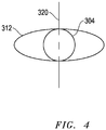
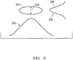
- the reference aperture 304 is moved so that the beam is then directed through a shaped elliptical working aperture 312 ( FIG. 4 ) to form a working beam 313 ( FIG. 6 ) having an approximately elliptical shape with an associated working current.
- Working beam 313 is optimized using the selected settings or parameters of the first and second lenses and stigmator that were used to optimize reference beam 302.
- Working beam 313 has a dimension, such as minor axis 314 that substantially corresponds to dimension 306 of reference beam 302 (as best seen in FIG. 4 ) so that when optimized produces a current density profiles 315 and 316 with a sharp edge 318 for milling the work piece. As seen in FIG.
- dimension 314 of working beam 313 is aligned along the location within the optical column of dimension 306 of reference beam 302 so that dimension 314 of working beam 313 and dimension 306 of reference beam 302 extend along an axis 320, which preferably extends substantially perpendicular to a work piece cutting face so that a leading edge or cutting edge 318 of the working beam cuts or mills the material.
- working beam 313 has a sharp cutting edge 318 to provide precision processing while operating with a high current so that faster milling operations can be achieved in less time than has been possible in prior art methods.
- the size of the beam is dependent on the required beam current for a particular application.
- the diameter of the round reference beam will determine the minor axis of the shaped working beam aperture that is actually used in the slice milling. Therefore, a beam having a required specified current will result in a beam having a defined dimension. This will determine the minor axis of the shaped working beam aperture.
- the major axis of the shaped working beam aperture is also determined by beam current. For example, if the application requires a beam current that is twice that of the beam current used to form the round reference beam, the shaped working beam aperture is formed having a major axis that is twice that of the minor axis.
- the shaped working beam aperture is formed having a major axis that is three times that of the minor axis.
- This 3:1 ratio (major axis to minor axis) is generally applicable to beams up to about 750 pA.
- the major-to-minor axis ratio for shaped beam apertures with current higher than 750 pA is generally 2:1. That is, the major axis is twice that of the minor axis.
- the preferred embodiment of the invention utilizes an elliptically shaped working beam apertures it is to be understood that the invention encompasses other non-round beam aperture shapes.
- a rectangular beam apertures or other non-round shaped beam apertures may be used.
- these other non-round shaped beams are focused and aligned in the method described above in which a round reference beam is first optimized using selected optical component parameters and then the non-round shaped working beam is optimized using the selected optical component parameters used to align the round reference beam.
- FIG. 7 schematically shows one embodiment of a shaped focused ion beam (“FIB") system suitable for use with the present invention. Note that the identified components are not required in all applications. Moreover, the depicted sizes and relative positions are not necessarily to scale or consistent with all configurations. Also, this system can be used either for a projection approach or for an angular aperture approach depending on the particular configuration of the optical components in the FIB column.
- FIB focused ion beam
- the depicted shaped beam system includes an evacuated chamber 410 having an ion source 414, such as a liquid metal ion source or a plasma microbeam ion source, and a focusing column 417, which includes an optical system such as is shown in the block diagram of FIG. 5 for defining a desired shaped ion beam 418 and focusing it onto a target work piece 422.
- an ion source 414 such as a liquid metal ion source or a plasma microbeam ion source
- a focusing column 417 which includes an optical system such as is shown in the block diagram of FIG. 5 for defining a desired shaped ion beam 418 and focusing it onto a target work piece 422.
- Focusing column 417 uses a two-lens ion focusing structure for generating an aperture shaped beam.
- the lenses and other "optical" elements used with focused ion beams use electrostatic or magnetic fields to control ions in the beam, and that the optical elements are controlling a stream of ions.
- the designs may include only one or up to several lenses.
- the principles of the specific aperture approach are discussed using this FIB system, they apply equally to other charged particle systems (such as e-beam systems) as long as suitable optical components for such other systems are used.
- Unfocused ion beam 416 passes from source 414 through column 417 emitting a shaped beam 418 toward work piece 422, which is removably mounted on movable X-Y stage 424 within the lower portion of chamber 426.
- the work piece 422 can be any material that may be worked upon by beam 418 to achieve a desired result. It could comprise, for example, a semiconductor device, photo-lithographic mask, magnetic storage head, and the like. The particular shaped beam parameters being used will depend on the object material, we well as on the result that is desired.
- An ion pump 428 is employed for evacuating neck portion 410.
- the chamber 426 is evacuated with turbo-molecular and mechanical pumping system 430 under the control of vacuum controller 432.
- High voltage power supply 434 is connected to liquid metal ion source 414, as well as to appropriate electrodes in focusing column 417 for forming an approximately 30 keV ion beam 418 and directing the same downwardly.
- Controller 436 is coupled to the focusing column 417 and in particular to deflection plates, a stigmator, and to a variable axis, variable shape aperture within the focusing column 417 in order to control beam 418, for example, to rotate, deform, and/or re-position it on the target work piece 422 in accordance with a desired task.
- controller 436 Through controller 436, a user can control beam 418 to be scanned in a desired manner through commands entered into a conventional user interface (not shown). Alternatively, controller 436 may access a memory storage device to upload instructions to cause the controller to control the system to scan a path, using a predefined beam shape.
- the source 414 typically provides a metal ion beam of gallium from a field ion emission source (liquid metal ion source (LMIS)), although other ion sources, such as a multicusp or other plasma ion source, can be used. While this source is typically capable of being focused into a sub one-hundredth micron wide beam at the work piece 422.
- An electron multiplier 440 used for detecting secondary emission for imaging is connected to a power supply and controls 445 and to video circuit 442, which supplies drive for video monitor 444 for viewing work piece 422 as it is being worked upon.
- a gas source 446 is located inwardly of the side of chamber 426 by translation device 448 adapted for positioning the source via support means within bellows 452.
- Gas source 446 includes a reservoir 454 with a heater, which may comprise a membrane type heater and can be used for raising the temperature of a compound within reservoir 454 to a temperature for providing a suitable stream of molecules for beam-induced reactions as hereinafter more fully disclosed.
- a transfer tube or nozzle 456 comprising a capillary tube provided by a hypodermic needle extends from reservoir 454 and is connected thereto via control valve 458 adapted for releasing gaseous vapor.
- the nozzle is extended and translated in orthogonal directions substantially perpendicular to its axis employing translation apparatus 448, so that gaseous vapor can be aimed directly toward a region on the top surface of the work piece 422.
- a door 460 is opened for inserting a work piece 422 on stage 424 which may be heated.
- the door is interlocked so that it cannot be opened if the temperature in reservoir 454 is substantially above room temperature.
- a gate valve is closed before door 460 can be opened to seal off the ion source and focusing column apparatus.
- valve 458 may be opened by withdrawing an actuator rod from outside the apparatus to open and regulate the position of valve plunger, while the nozzle 456 is directed towards the desired area of the work piece.
- Bellows 452 accommodates movement of the nozzle assembly and reservoir relative to the work piece without affecting the vacuum with chamber 426.
- the vacuum control system along with the heater of gaseous vapor source 446 are operated to provide an appropriate vapor pressure condition for establishing a gaseous vapor flux in chamber as directed toward substrate 422 for etching or depositing material.
- the reservoir is heated to a predetermined temperature.
- the high voltage power supply 434 provides an appropriate acceleration voltage to electrodes in ion beam column 417 for energizing and focusing ion beam 418. When it strikes the work piece having condensed gaseous vapor adhered thereupon, the ion beam provides energy for initiating a reaction between the gaseous compound and the substrate and for either enhanced etching/milling of or material deposition upon the sample.
- the vacuum system provides a vacuum of between approximately 1x10 -7 Torr and 5x10 -4 Torr within chamber 426.
- the chamber background pressure is suitably about 1x10 -5 Torr.
- the gaseous source 446 is heated to a temperature for providing an appropriate gaseous flux via the capillary tube of the hypodermic needle, while the metal ion source and focusing column are suitably controlled for generating a corresponding appropriate ion flux. Skilled persons can readily determine appropriate pressures and gas flows for any particular application.
- Some embodiments of the invention provide a method for charged particle beam processing of a work piece, comprising:
- the reference aperture is round and the working aperture is not round.
- the reference aperture is round and the working aperture is elliptical, the minor axis of the ellipse having the same dimension as the diameter of the round aperture.
- the working aperture is rectangular or semi-circular.
- the adjusting the optical components to provide a desired reference beam profile at the work piece surface comprises focusing and reducing the stigmation of the reference beam.
- the optical components include a first lens, a second lens, and a stigmator and adjusting the optical components to provide a desired reference beam profile at the work piece surface comprises setting the focus of the first and second lenses and adjusting the stigmator to reduce stinmation of the reference beam.
- Some embodiments of the invention provide a method of processing a sample in a beam system by directing a beam at a substantial normal angle to a surface of the sample and moving the beam along a path to produce a feature that is substantially normal to the surface of the sample, comprising:
- Some embodiments of the invention provide a beam system for producing a shaped beam, comprising:
- the present invention was described above in the context of use in a focused ion beam system for demonstrative purposes. However, it will be understood that the methods of the present invention may also be employed in other scanned systems, such as electron beam systems including scanning electron microscopes and scanning transmission electron microscopes.
- a preferred method or apparatus of the present invention has many novel aspects, and because the invention can be embodied in different methods or apparatus for different purposes, not every aspect need be present in every embodiment. Moreover, many of the aspects of the described embodiments may be separately patentable.
- the invention has broad applicability and can provide many benefits as described and shown in the examples above. The embodiments will vary greatly depending upon the specific application, and not every embodiment will provide all of the benefits and meet all of the objectives that are achievable by the invention.
- embodiments of the present invention can be implemented via computer hardware, a combination of both hardware and software, or by computer instructions stored in a non-transitory computer-readable memory.
- the methods can be implemented in computer programs using standard programming techniques-including a non- transitory computer-readable storage medium configured with a computer program, where the storage medium so configured causes a computer to operate in a specific and predefined manner-according to the methods and figures described in this Specification.
- Each program may be implemented in a high level procedural or object oriented programming language to communicate with a computer system.
- the programs can be implemented in assembly or machine language, if desired. In any case, the language can be a compiled or interpreted language.
- the program can run on dedicated integrated circuits programmed for that purpose.
Landscapes
- Chemical & Material Sciences (AREA)
- Analytical Chemistry (AREA)
- Physics & Mathematics (AREA)
- Engineering & Computer Science (AREA)
- Plasma & Fusion (AREA)
- Electron Beam Exposure (AREA)
- Welding Or Cutting Using Electron Beams (AREA)
- Electron Sources, Ion Sources (AREA)
Abstract
emitting ions from an ion source;
forming the ions into an ion beam;
directing the ion beam through an optical column having optical components positioned along an optical axis;
directing the ion beam through a reference aperture (304) to form a reference beam having a reference beam current and a reference beam shape;
adjusting the optical components to provide a desired reference beam profile at the work piece surface; and
processing the work piece by directing the ion beam through a working aperture (312) instead of through the reference aperture to form a working beam, the working beam having a working beam current that is greater than the reference beam current and a working beam shape on the work piece surface that is different from the reference beam shape;
wherein the reference beam profile includes an edge profile along a first direction and the working beam has the same edge profile along the same direction, thereby providing a higher current working beam to process a work piece more rapidly than the reference beam, while providing an edge sharpness that is similar to that of the reference beam in at least one direction.
Description
- The present invention relates to a method of optimizing a shaped beam, such as an electron beam, ion beam, or laser beam, for precision milling applications.
- Charged particle beams, laser beams, and neutral particle beams are used in a variety of microfabrication applications, such as fabrication of semiconductor circuitry and microelectromechanical assemblies. The term "microfabrication" is used to include creating and altering structures having dimensions of tens of microns or less, including nanofabrication processes. "Processing" a sample refers to the microfabrication of structures on that sample. In charged particle beam systems, such as electron microscopes or focused ion beam (FIB) systems, a source generates charged particles which are then focused by an optical column into a beam and directed onto the surface of a target to be imaged and/or processed. In the column, this beam may be deflected to move it around on the target surface. As smaller and smaller structures are fabricated, it is necessary to direct the beam more precisely.
- One aspect of semiconductor manufacturing that requires accurate beam positioning is the extraction of thin samples for transmission electron microscopy. Such samples are used for monitoring the semiconductor fabrication process. In some applications known as slice and view applications a "slice" or thin, vertical sample, referred to as a lamella, is milled out of the surface of a work piece. The lamella is extracted to leave an exposed cross-sectional surface to be imaged, for example, by a transmission electron microscope ("TEM"). In order to obtain a cross-sectional surface that is as flat and vertical as possible a clean, fine cut from the beam is required.
- Typically, a beam controller directs the beam to specified coordinates or along a specified path using a beam controller coordinate system in response to a stored program, pattern generator, or operator instructions to perform a specific process. Ideally, the beam converges in the plane of the work piece or target specimen. However, if the system is not calibrated, the beam may converge before or after the sample plane causing the beam to be unfocussed. Also, the beam may exhibit stigmatic effects. Moreover, there may be rotational misalignment between the axis of the specimen and the scan axis of the beam. Or there may exist a non-orthogonal relationship between the beam axes. Further, the scan gain may be different in each of the orthogonal scan directions so that in one direction the image appears "stretched". The scanned beam system must therefore be calibrated to eliminate or at least minimize these errors. To overcome these problems a beam system will typically provide control elements to achieve calibration. For example, an electrostatic lens system may be provided to cause the beam to converge at the correct focal point and a stigmator may be provided to adjust for stigmation effects.
- For precision processing in which a charged particle beam is used to mill material from the surface of a target the milling rate is roughly proportional to the beam current. For example, higher beam currents are preferred when it is desired to quickly remove material. However, beams using higher current are less precise and typically result in a damaged or undesirable sample. Therefore, lower beam currents have been used for more precision processing applications. A beam having a lower beam current, that is, fewer charged particles per second, can typically be focused to a smaller size than a beam having a higher current. For example, a small beam with a lower current is more precise and results in less unwanted damage to the sample. See, for example,
U.S. Pat. No. 6,949,756 , entitled "Shaped And Low Density Focused Ion Beams" to Gerlach et al., assigned to the assignee of the present invention, which is hereby incorporated by reference. However, use of lower current beams reduces the rate of material removal and results in a longer processing time. - It is increasingly more desirable to decrease processing time. Non-round or "shaped" beams have been developed in order to increase milling speed. Shaped beams can be generated having a straight edge for cutting away material, and at the same time, having their beam spot shapes of a size with enough beam current for quickly removing material. See, for example,
U.S. Pat. No. 6,977,386 , entitled "Angular Aperture Shaped Beam System And Method" to Gerlach et al., assigned to the assignee of the present invention, which is hereby incorporated by reference. - In some systems the beam is shaped by an aperture plate positioned within the optical column having one or more selectable beam-defining apertures (BDAs) through which the beam passes. The BDAs are typically holes in a metal strip, which are intended to block the off-axis charged particles and to pass the ones used to form the beam. There are typically several BDAs, or holes, in a metal strip, and the apertures can be switched depending on the application by moving the strip so that a hole of a different size and/or shape is positioned in the path of the beam. For example, a beam having a desired geometrically shaped spot is formed by a shaping aperture typically disposed between one or more lenses in a charged particle column. To achieve calibration, control elements may include a two-lens focusing column in which the first lens forms an image of the beam at or near the plane of the second lens and the second lens forms an image of the shaping aperture on the target plane. The lenses and other "optical" elements (i.e., a stigmator) in the beam column may use electrostatic or magnetic fields to align the beam along the optical axis and focus the beam on the target plane.
- It is important for the beam to be accurately focused and compensated for aberrations. Typically, a beam is focused and aligned using known values for the optical elements such as the lenses and stigmator from a table of values that have been input and stored in a program or through operator instructions based on desired current. For example,
FIGS. 1A and 1B show spot burn arrays for a 130 pA round beam.FIG. 1A shows aspot burn array 100 where the second lens focus was varied in a serpentine fashion from top to bottom and left to right. The beam was optimized using an image sharpness routine based on auto focus so that thecenter spot 102 is near optimal.FIG. 1B shows aspot burn array 104 where the stigmation was varied along X and Y directions. The beam was optimized using an image sharpness routine based on stigmation so that thecenter spot 106 is near optimal. - However, it is difficult to predict the optimal focus and stigmator settings for shaped beams as illustrated in
Figs. 2A and 2B , which show spot burn arrays for a 420 pA shaped beam formed with an elliptical aperture.FIG. 2A shows aspot burn array 108 where the second lens focus was varied in a serpentine fashion from top to bottom and from left to right. The beam was optimized using an image sharpness routine based on auto focus on its corresponding round beam so that thecenter spot 110 is near optimal.FIG. 2B shows aspot burn array 112 where the stigmation was varied along X and Y directions. The beam was optimized using an image sharpness routine based on stigmation on its corresponding round beam so that thecenter spot 114 is near optimal. However, as can be seen inFIGS. 2A and 2B theoptimal spots - What is needed is a method and system for optimizing a shaped beam having a sharp edge to achieve clean and fine milling operations while having a high current for rapid processing.
- The present invention provides a method for optimizing a shaped beam having a sharp edge for making sufficiently precise cuts and a high beam current for faster processing. An ion beam is directed along an optical column through a reference aperture to form a reference beam that has a preferred shape and an associated reference current. The reference beam is aligned with the axis of the optical column and focused onto a target plane using selected parameters of the optical components within the optical column so that the reference beam has a profile with a sharp edge. The ion beam is then directed through a working aperture to form a working beam for use in a processing application. The working beam has a different shape from the reference beam and an associated working current that is higher than the reference current. The working beam is aligned with the axis of the optical column and focused onto the target plane using the selected optical component parameters used to align and focus the reference beam. This produces a working beam that has a profile with at least one sharp edge that substantially corresponds to the sharp edge produced by the reference beam but has a higher current. The reference aperture and working aperture have at least one corresponding dimension that produces the sharp edge. In a preferred embodiment, the reference aperture is round and has a diameter that extends along an axis. The working aperture has a shape with a minor diameter, such as an ellipse, that extends along an axis with the same alignment as the reference aperture axis. Preferably, the diameter of the reference aperture is substantially similar to the minor diameter of the working aperture to produce a working beam that has a sharp edge corresponding to the sharp edge of the reference beam but the shape of the working aperture produces a beam with a higher current.
- The foregoing has outlined rather broadly the features and technical advantages of the present invention in order that the detailed description of the invention that follows may be better understood. Additional features and advantages of the invention will be described hereinafter. It should be appreciated by those skilled in the art that the conception and specific embodiments disclosed may be readily utilized as a basis for modifying or designing other structures for carrying out the same purposes of the present invention. It should also be realized by those skilled in the art that such equivalent constructions do not depart from the scope of the invention as set forth in the appended claims.
- For a more thorough understanding of the present invention, and advantages thereof, reference is now made to the following descriptions taken in conjunction with the accompanying drawings, in which:
-
FIG. 1A shows a spot burn array for a round beam with a varied second lens focus. -
FIG. 1B shows a spot burn array for a round beam with varied stigmation along X and Y directions. -
FIG. 2A shows a spot burn array for a beam formed using an elliptical aperture with a varied second lens focus. -
FIG. 2B shows a spot burn array for a beam formed using an elliptical aperture with varied stigmation along X and Y directions. -
FIG. 3 shows an image of a lamella that has been milled from a substrate. -
FIG. 4 shows the relationship of the reference beam aperture to the working beam aperture. -
FIG. 5 shows the shape and corresponding beam profile of the reference beam. -
FIG. 6 illustrates the approximate shape and corresponding beam profile of the working beam. -
FIG. 7 shows a focused ion beam system in which a shaped beam according to this invention can be produced and optimized. - In accordance with preferred embodiments of the present invention, an ion optical column in a focused ion beam system produces a shaped beam having one or more geometric features having a sharp resolution that is focused and aligned with the axis of the optical column.
- Microstructure milling tasks such as cross-sectional cutting for imaging, for example, require beams with at least one sharp edge for cutting away a slice that leaves a straight, "clean" cross-sectional surface. The beam spot has a leading edge, which is a sharp edge of the spot that can be used to mill away sharp, vertical faces. The beam spot also has width and depth dimensions. Some applications may require a beam having a minimized depth or width to produce a sharp edge with a high current for faster milling. For example,
FIG. 3 shows an image of alamella 200 that has been milled out of asubstrate 202.Lamella 200 is then extracted and prepared for imaging. - In a preferred system the beam is shaped by an aperture plate positioned within the optical column having one or more selectable beam-defining apertures (BDAs) through which the beam passes. The BDAs are typically holes in a metal strip, which are intended to block the off-axis charged particles and to pass the ones used to form the beam. There are typically several BDAs, or holes, in a metal strip, and the apertures can be switched depending on the application by moving the strip so that a hole of a different size and/or shape is positioned in the path of the beam. For example, a beam having a desired spot is formed by a shaping aperture typically disposed between one or more lenses in a charged particle column. To achieve calibration, control elements may include a two-lens focusing column in which the first lens forms an approximately collimated beam from the point source (liquid metal ion source or LMIS) and the second lens forms an image of the point source with the angular distribution shaped by the aperture. The lenses and other "optical" elements (i.e., a stigmator) in the beam column may use electrostatic or magnetic fields to align the beam along the optical axis and focus the beam on the target plane.
- A preferred method of this invention provides a shaped working beam for processing a work piece having the cutting edge sharpness of a round beam but operates with more current than can be achieved with a round beam. Although the preferred embodiment of the invention is described using a round reference beam and an approximately elliptically shaped working beam, it should be understood that the method of this invention includes various beam shapes including but not limited to beams formed from apertures with round, elliptical, rectangular, semi-circular (D-shaped), or other shapes.
- In lamellae milling it is typical to use a beam having a current of between about 40 - 90 pA to provide a beam having a sharp edge to make a clean cut and prevent damage to the lamella. Beams having current within this range are typically round. However, a higher beam current is desired to decrease processing time. Higher beam current can be achieved using a shaped (non-round) beam such as, for example, an elliptical beam. However, it is difficult to optimize (align and focus) shaped beams to have a sharp cutting edge. A preferred method of this invention provides a shaped beam having a high enough beam current for to achieve fast milling yet has a sharp cutting edge to make a clean cut.
- In a preferred embodiment seen in
FIGS. 4-6 , a beam for cross-sectional slicing is provided by first forming a reference beam 302 (FIG. 5 ) through a reference aperture 304 (FIG. 4 ) having an associated reference current to have a round shape. In one example, the reference aperture may have a diameter of between 10 microns - 1 mm and the reference current may be in the range of about 1-100000 pA.Reference beam 302 is optimized to be aligned with the axis of the optical column and focused onto a target plane (or work piece) using a set of selected settings or parameters of the optical components within the optical column. For example, parameters for the first and second lenses and the stigmator can be manipulated using known values to achieve desired optimization of the beam. The selected optical settings or parameters may vary depending on the application. As seen inFIG. 5 ,reference beam 302 has a dimension, such asdiameter 306, that producescurrent density profiles sharp edge 310 suitable for milling or cutting away a slice of a work piece. - To create a beam having a correspondingly sharp edge with a higher current for milling, the
reference aperture 304 is moved so that the beam is then directed through a shaped elliptical working aperture 312 (FIG. 4 ) to form a working beam 313 (FIG. 6 ) having an approximately elliptical shape with an associated working current. Workingbeam 313 is optimized using the selected settings or parameters of the first and second lenses and stigmator that were used to optimizereference beam 302. Workingbeam 313 has a dimension, such asminor axis 314 that substantially corresponds todimension 306 of reference beam 302 (as best seen inFIG. 4 ) so that when optimized produces acurrent density profiles sharp edge 318 for milling the work piece. As seen inFIG. 4 , during optimization,dimension 314 of workingbeam 313 is aligned along the location within the optical column ofdimension 306 ofreference beam 302 so thatdimension 314 of workingbeam 313 anddimension 306 ofreference beam 302 extend along anaxis 320, which preferably extends substantially perpendicular to a work piece cutting face so that a leading edge or cuttingedge 318 of the working beam cuts or mills the material. Thus, workingbeam 313 has asharp cutting edge 318 to provide precision processing while operating with a high current so that faster milling operations can be achieved in less time than has been possible in prior art methods. - The size of the beam is dependent on the required beam current for a particular application. The diameter of the round reference beam will determine the minor axis of the shaped working beam aperture that is actually used in the slice milling. Therefore, a beam having a required specified current will result in a beam having a defined dimension. This will determine the minor axis of the shaped working beam aperture. The major axis of the shaped working beam aperture is also determined by beam current. For example, if the application requires a beam current that is twice that of the beam current used to form the round reference beam, the shaped working beam aperture is formed having a major axis that is twice that of the minor axis. Likewise, if the application requires a beam current that is three times that of the beam current used to form the round reference beam, the shaped working beam aperture is formed having a major axis that is three times that of the minor axis. This 3:1 ratio (major axis to minor axis) is generally applicable to beams up to about 750 pA. The major-to-minor axis ratio for shaped beam apertures with current higher than 750 pA is generally 2:1. That is, the major axis is twice that of the minor axis.
- Although the preferred embodiment of the invention utilizes an elliptically shaped working beam apertures it is to be understood that the invention encompasses other non-round beam aperture shapes. For example, a rectangular beam apertures or other non-round shaped beam apertures may be used. It is also understood that these other non-round shaped beams are focused and aligned in the method described above in which a round reference beam is first optimized using selected optical component parameters and then the non-round shaped working beam is optimized using the selected optical component parameters used to align the round reference beam.
-
Figure 7 schematically shows one embodiment of a shaped focused ion beam ("FIB") system suitable for use with the present invention. Note that the identified components are not required in all applications. Moreover, the depicted sizes and relative positions are not necessarily to scale or consistent with all configurations. Also, this system can be used either for a projection approach or for an angular aperture approach depending on the particular configuration of the optical components in the FIB column. - The depicted shaped beam system includes an evacuated
chamber 410 having anion source 414, such as a liquid metal ion source or a plasma microbeam ion source, and a focusingcolumn 417, which includes an optical system such as is shown in the block diagram ofFIG. 5 for defining a desired shapedion beam 418 and focusing it onto atarget work piece 422. (It should be recognized that the term "focus" is used broadly, refers generally to the re-directing of source ions into a beam directed to the target work piece, and covers shaped beams that are technically defocused with respect to a first-order focal plane.) Focusingcolumn 417 uses a two-lens ion focusing structure for generating an aperture shaped beam. Skilled persons will understand that the lenses and other "optical" elements used with focused ion beams use electrostatic or magnetic fields to control ions in the beam, and that the optical elements are controlling a stream of ions. Also, the designs may include only one or up to several lenses. Moreover, while the principles of the specific aperture approach are discussed using this FIB system, they apply equally to other charged particle systems (such as e-beam systems) as long as suitable optical components for such other systems are used. -
Unfocused ion beam 416 passes fromsource 414 throughcolumn 417 emitting a shapedbeam 418 towardwork piece 422, which is removably mounted on movableX-Y stage 424 within the lower portion ofchamber 426. Thework piece 422 can be any material that may be worked upon bybeam 418 to achieve a desired result. It could comprise, for example, a semiconductor device, photo-lithographic mask, magnetic storage head, and the like. The particular shaped beam parameters being used will depend on the object material, we well as on the result that is desired. An ion pump 428 is employed for evacuatingneck portion 410. Thechamber 426 is evacuated with turbo-molecular andmechanical pumping system 430 under the control ofvacuum controller 432. - High
voltage power supply 434 is connected to liquidmetal ion source 414, as well as to appropriate electrodes in focusingcolumn 417 for forming an approximately 30keV ion beam 418 and directing the same downwardly.Controller 436 is coupled to the focusingcolumn 417 and in particular to deflection plates, a stigmator, and to a variable axis, variable shape aperture within the focusingcolumn 417 in order to controlbeam 418, for example, to rotate, deform, and/or re-position it on thetarget work piece 422 in accordance with a desired task. (In some systems, the deflection plates, stigmator, and/or other optical devices are placed outside of the ion column after the final lens, as is well known in the art.) Throughcontroller 436, a user can controlbeam 418 to be scanned in a desired manner through commands entered into a conventional user interface (not shown). Alternatively,controller 436 may access a memory storage device to upload instructions to cause the controller to control the system to scan a path, using a predefined beam shape. - The
source 414 typically provides a metal ion beam of gallium from a field ion emission source (liquid metal ion source (LMIS)), although other ion sources, such as a multicusp or other plasma ion source, can be used. While this source is typically capable of being focused into a sub one-hundredth micron wide beam at thework piece 422. Anelectron multiplier 440 used for detecting secondary emission for imaging is connected to a power supply and controls 445 and tovideo circuit 442, which supplies drive forvideo monitor 444 for viewingwork piece 422 as it is being worked upon. - A
gas source 446 is located inwardly of the side ofchamber 426 bytranslation device 448 adapted for positioning the source via support means within bellows 452.U.S. Pat. No. 5,435,850 to Rasmussen for a "Gas Injection System" andU.S. Pat. No. 5,851,413 to Casella, et al. for "Gas Delivery Systems for Particle Beam Processing," both assigned to the assignee of the present invention, discloses apparatuses for introducing and directing gaseous vapor toward thework piece 422.Gas source 446 includes areservoir 454 with a heater, which may comprise a membrane type heater and can be used for raising the temperature of a compound withinreservoir 454 to a temperature for providing a suitable stream of molecules for beam-induced reactions as hereinafter more fully disclosed. A transfer tube ornozzle 456 comprising a capillary tube provided by a hypodermic needle extends fromreservoir 454 and is connected thereto viacontrol valve 458 adapted for releasing gaseous vapor. The nozzle is extended and translated in orthogonal directions substantially perpendicular to its axis employingtranslation apparatus 448, so that gaseous vapor can be aimed directly toward a region on the top surface of thework piece 422. - A
door 460 is opened for inserting awork piece 422 onstage 424 which may be heated. The door is interlocked so that it cannot be opened if the temperature inreservoir 454 is substantially above room temperature. A gate valve is closed beforedoor 460 can be opened to seal off the ion source and focusing column apparatus. - When
reservoir 454 is raised to a desired temperature for vaporizing the compound withinreservoir 454,valve 458 may be opened by withdrawing an actuator rod from outside the apparatus to open and regulate the position of valve plunger, while thenozzle 456 is directed towards the desired area of the work piece.Bellows 452 accommodates movement of the nozzle assembly and reservoir relative to the work piece without affecting the vacuum withchamber 426. - The vacuum control system along with the heater of
gaseous vapor source 446 are operated to provide an appropriate vapor pressure condition for establishing a gaseous vapor flux in chamber as directed towardsubstrate 422 for etching or depositing material. To establish a given gaseous flux, the reservoir is heated to a predetermined temperature. - The high
voltage power supply 434 provides an appropriate acceleration voltage to electrodes inion beam column 417 for energizing and focusingion beam 418. When it strikes the work piece having condensed gaseous vapor adhered thereupon, the ion beam provides energy for initiating a reaction between the gaseous compound and the substrate and for either enhanced etching/milling of or material deposition upon the sample. - As mentioned earlier, the vacuum system provides a vacuum of between approximately 1x10⁻⁷Torr and 5x10⁻⁴Torr within
chamber 426. With emission of gaseous vapor, the chamber background pressure is suitably about 1x10⁻⁵Torr. In an exemplary embodiment, thegaseous source 446 is heated to a temperature for providing an appropriate gaseous flux via the capillary tube of the hypodermic needle, while the metal ion source and focusing column are suitably controlled for generating a corresponding appropriate ion flux. Skilled persons can readily determine appropriate pressures and gas flows for any particular application. - Some embodiments of the invention provide a method for charged particle beam processing of a work piece, comprising:
- emitting ions from an ion source;
- forming the ions into an ion beam;
- directing the ion beam through an optical column having optical components positioned along an optical axis;
- directing the ion beam through a reference aperture to form a reference beam having a reference beam current and a reference beam shape;
- adjusting the optical components to provide a desired reference beam profile at the work piece surface; and
- processing the work piece by directing the ion beam through a working aperture instead of through the reference aperture to form a working beam, the working beam having a working beam current that is greater than the reference beam current and a working beam shape on the work piece surface that is different from the reference beam shape;
- wherein the reference beam profile includes an edge profile along a first direction and the working beam has the same edge profile along the same direction, thereby providing a higher current working beam to process a work piece more rapidly than the reference beam, while providing an edge sharpness that is similar to that of the reference beam in at least one direction.
- In some embodiments, the reference aperture is round and the working aperture is not round.
- In some embodiments, the reference aperture is round and the working aperture is elliptical, the minor axis of the ellipse having the same dimension as the diameter of the round aperture.
- In some embodiments, the working aperture is rectangular or semi-circular.
- In some embodiments, the adjusting the optical components to provide a desired reference beam profile at the work piece surface comprises focusing and reducing the stigmation of the reference beam.
- In some embodiments, the optical components include a first lens, a second lens, and a stigmator and adjusting the optical components to provide a desired reference beam profile at the work piece surface comprises setting the focus of the first and second lenses and adjusting the stigmator to reduce stinmation of the reference beam.
- Some embodiments of the invention provide a method of processing a sample in a beam system by directing a beam at a substantial normal angle to a surface of the sample and moving the beam along a path to produce a feature that is substantially normal to the surface of the sample, comprising:
- directing the beam through an optical column having optical components extending along an axis;
- forming a reference-shaped beam through a reference aperture;
- optimizing the reference-shaped beam onto a target plane using selected optical component parameters so that the reference-shaped beam is aligned with the axis of the optical column and focused to have a profile forming a sharp edge and having an associated reference current;
- forming a working-shaped beam through a working aperture; and
- optimizing the working-shaped beam onto the target plane with selected optical component parameters for optimizing the reference-shaped beam so that the working-shaped beam is aligned with the axis of the optical column and focused to have a profile forming a sharp edge and having an associated working current.
- Some embodiments of the invention provide a beam system for producing a shaped beam, comprising:
- an ion source for producing a beam;
- an optical column including a first lens and a second lens through which the beam extends;
- an aperture plate positioned between the first and second lenses, the aperture plate having a reference aperture shape and a working aperture having a working aperture shape different from the reference aperture shape;
- a controller for controlling the operation of the beam system in accordance with stored computer instructions; and
- a computer readable memory storing computer instructions for carrying out the method of any of the above claims.
- The present invention was described above in the context of use in a focused ion beam system for demonstrative purposes. However, it will be understood that the methods of the present invention may also be employed in other scanned systems, such as electron beam systems including scanning electron microscopes and scanning transmission electron microscopes.
- A preferred method or apparatus of the present invention has many novel aspects, and because the invention can be embodied in different methods or apparatus for different purposes, not every aspect need be present in every embodiment. Moreover, many of the aspects of the described embodiments may be separately patentable. The invention has broad applicability and can provide many benefits as described and shown in the examples above. The embodiments will vary greatly depending upon the specific application, and not every embodiment will provide all of the benefits and meet all of the objectives that are achievable by the invention.
- It should be recognized that embodiments of the present invention can be implemented via computer hardware, a combination of both hardware and software, or by computer instructions stored in a non-transitory computer-readable memory. The methods can be implemented in computer programs using standard programming techniques-including a non- transitory computer-readable storage medium configured with a computer program, where the storage medium so configured causes a computer to operate in a specific and predefined manner-according to the methods and figures described in this Specification. Each program may be implemented in a high level procedural or object oriented programming language to communicate with a computer system. However, the programs can be implemented in assembly or machine language, if desired. In any case, the language can be a compiled or interpreted language. Moreover, the program can run on dedicated integrated circuits programmed for that purpose.
- The invention could be used to prepare samples of any suitable material. The terms "work piece," "sample," "substrate," and "specimen" are used interchangeably in this application unless otherwise indicated. Further, whenever the terms "automatic," "automated," or similar terms are used herein, those terms will be understood to include manual initiation of the automatic or automated process or step.
- In the following discussion and in the claims, the terms "including" and "comprising" are used in an open-ended fashion, and thus should be interpreted to mean "including, but not limited to ...." To the extent that any term is not specially defined in this specification, the intent is that the term is to be given its plain and ordinary meaning. The accompanying drawings are intended to aid in understanding the present invention and, unless otherwise indicated, are not drawn to scale. Particle beam systems suitable for carrying out the present invention are commercially available, for example, from FEI Company, the assignee of the present application.
- Although the present invention and its advantages have been described in detail, it should be understood that various changes, substitutions and alterations can be made to the embodiments described herein without departing from the invention as defined by the appended claims. Moreover, the present application is not intended to be limited to the particular embodiments of the process, machine, manufacture, composition of matter, means, methods and steps described in the specification. As one of ordinary skill in the art will readily appreciate from the disclosure of the present invention, processes, machines, manufacture, compositions of matter, means, methods, or steps, presently existing or later to be developed that perform substantially the same function or achieve substantially the same result as the corresponding embodiments described herein may be utilized according to the present invention. Accordingly, the appended claims are intended to include such processes, machines, manufacture, compositions of matter, means, methods, or steps.
Claims (9)
- A method for charged particle beam processing of a work piece (422), comprising:emitting ions from an ion source (414);forming the ions into an ion beam;directing the ion beam through an optical column (417) having optical components positioned along an optical axis;directing the ion beam through a reference aperture (304) to form a first beam having a first beam current and a first beam shape; andadjusting the optical components to provide a desired first beam profile at the work piece surface; andcharacterized in that:the first beam comprises a reference beam (302) having a reference beam current and a reference beam shape and adjusting the optical components to provide a desired first beam profile at the work piece surface comprises providing a reference beam profile at the work piece surface;processing the work piece by directing the ion beam through a working aperture (312) instead of through the reference aperture to form a working beam (313), the working beam having a working beam current that is greater than the reference beam current and a working beam shape on the work piece surface that is different from the reference beam shape;wherein the reference beam profile includes an edge profile along a first direction and the working beam has the same edge profile along the same direction, thereby providing a higher current working beam to process a work piece more rapidly than the reference beam, while providing an edge sharpness that is similar to that of the reference beam in at least one direction.
- The method of claim 1, wherein the reference aperture is round and the working aperture is not round.
- The method of claims 1 or claim 2, wherein the reference aperture is round and the working aperture is elliptical, the minor axis of the ellipse having the same dimension as the diameter of the round aperture.
- The method of claim 1 or claim 2, wherein the working aperture is rectangular or semi-circular.
- The method of any of the above claims, wherein the adjusting the optical components to provide a desired reference beam profile at the work piece surface comprises focusing and reducing the stigmation of the reference beam.
- The method of any of the above claims, wherein the optical components include a first lens, a second lens, and a stigmator and adjusting the optical components to provide a desired reference beam profile at the work piece surface comprises setting the focus of the first and second lenses and adjusting the stigmator to reduce stinmation of the reference beam.
- A beam system for producing a shaped beam, comprising:an ion source (414) for producing a beam (418);an optical column (417) including a first lens and a second lens through which the beam extends;an aperture plate positioned between the first and second lenses, the aperture plate having a reference aperture shape and a working aperture having a working aperture shape different from the reference aperture shape; anda controller (436) for controlling the operation of the beam system in accordance with stored computer instructions;characterized by:a computer readable memory storing computer instructions for carrying out the method of any of the above claims.
- The beam system of claim 7, wherein the reference aperture is round and the working aperture is not round.
- The beam system of claim 7, wherein the reference aperture has at least one dimension that corresponds to at least one dimension of the working aperture.
Applications Claiming Priority (2)
| Application Number | Priority Date | Filing Date | Title |
|---|---|---|---|
| US201562249012P | 2015-10-30 | 2015-10-30 | |
| US14/981,164 US9679742B2 (en) | 2015-10-30 | 2015-12-28 | Method for optimizing charged particle beams formed by shaped apertures |
Publications (2)
| Publication Number | Publication Date |
|---|---|
| EP3166127A1 true EP3166127A1 (en) | 2017-05-10 |
| EP3166127B1 EP3166127B1 (en) | 2019-03-27 |
Family
ID=57211415
Family Applications (1)
| Application Number | Title | Priority Date | Filing Date |
|---|---|---|---|
| EP16196521.5A Active EP3166127B1 (en) | 2015-10-30 | 2016-10-31 | System and method for optimizing charged particle beams formed by shaped apertures |
Country Status (4)
| Country | Link |
|---|---|
| US (1) | US9679742B2 (en) |
| EP (1) | EP3166127B1 (en) |
| JP (1) | JP6812069B2 (en) |
| CN (1) | CN106683968B (en) |
Cited By (1)
| Publication number | Priority date | Publication date | Assignee | Title |
|---|---|---|---|---|
| WO2019025188A1 (en) * | 2017-08-02 | 2019-02-07 | Asml Netherlands B.V. | Systems and methods for charged particle flooding to enhance voltage contrast defect signal |
Families Citing this family (2)
| Publication number | Priority date | Publication date | Assignee | Title |
|---|---|---|---|---|
| JP6646150B2 (en) * | 2016-07-14 | 2020-02-14 | 株式会社日立ハイテクノロジーズ | Ion milling equipment |
| CN117293005A (en) | 2022-06-23 | 2023-12-26 | Fei 公司 | Focused ion beam systems and methods |
Citations (5)
| Publication number | Priority date | Publication date | Assignee | Title |
|---|---|---|---|---|
| US5435850A (en) | 1993-09-17 | 1995-07-25 | Fei Company | Gas injection system |
| US5851413A (en) | 1996-06-19 | 1998-12-22 | Micrion Corporation | Gas delivery systems for particle beam processing |
| US20040140438A1 (en) * | 2001-01-19 | 2004-07-22 | Gerlach Robert L. | Angular aperture shaped beam system and method |
| US6949756B2 (en) | 2000-01-21 | 2005-09-27 | Fei Company | Shaped and low density focused ion beams |
| US20120217152A1 (en) * | 2011-02-25 | 2012-08-30 | Fei Company | Method for Rapid Switching between a High Current Mode and a Low Current Mode in a Charged Particle Beam System |
Family Cites Families (14)
| Publication number | Priority date | Publication date | Assignee | Title |
|---|---|---|---|---|
| US5304811A (en) * | 1991-08-09 | 1994-04-19 | Fujitsu Ltd. | Lithography system using charged-particle beam and method of using the same |
| EP1369895B1 (en) * | 1996-03-04 | 2012-05-09 | Canon Kabushiki Kaisha | Electron beam exposure apparatus and method, and device manufacturing method |
| JP2002299207A (en) * | 2001-03-29 | 2002-10-11 | Toshiba Corp | Charged particle beam writing system |
| JP5033314B2 (en) * | 2004-09-29 | 2012-09-26 | 株式会社日立ハイテクノロジーズ | Ion beam processing apparatus and processing method |
| WO2007064956A1 (en) * | 2005-12-01 | 2007-06-07 | Cadence Design Systems, Inc. | System and method of electron beam writing |
| US20140353526A1 (en) * | 2008-09-01 | 2014-12-04 | D2S, Inc. | Method and system for forming high accuracy patterns using charged particle beam lithography |
| US20120221985A1 (en) * | 2011-02-28 | 2012-08-30 | D2S, Inc. | Method and system for design of a surface to be manufactured using charged particle beam lithography |
| US7759027B2 (en) * | 2008-09-01 | 2010-07-20 | D2S, Inc. | Method and system for design of a reticle to be manufactured using character projection lithography |
| US7914954B2 (en) * | 2008-09-09 | 2011-03-29 | D2S, Inc. | Stencil, stencil design system and method for cell projection particle beam lithography |
| US8253118B2 (en) | 2009-10-14 | 2012-08-28 | Fei Company | Charged particle beam system having multiple user-selectable operating modes |
| JP2013101929A (en) | 2011-11-07 | 2013-05-23 | Fei Co | Charged particle beam system aperture |
| US8745549B2 (en) * | 2012-02-05 | 2014-06-03 | D2S, Inc. | Method and system for forming high precision patterns using charged particle beam lithography |
| JP6018811B2 (en) * | 2012-06-19 | 2016-11-02 | 株式会社ニューフレアテクノロジー | Drift correction method and drawing data creation method |
| EP3043372B1 (en) | 2015-01-12 | 2017-01-04 | Fei Company | Method of modifying a sample surface layer from a microscopic sample |
-
2015
- 2015-12-28 US US14/981,164 patent/US9679742B2/en active Active
-
2016
- 2016-10-28 JP JP2016211552A patent/JP6812069B2/en active Active
- 2016-10-29 CN CN201611271120.0A patent/CN106683968B/en active Active
- 2016-10-31 EP EP16196521.5A patent/EP3166127B1/en active Active
Patent Citations (6)
| Publication number | Priority date | Publication date | Assignee | Title |
|---|---|---|---|---|
| US5435850A (en) | 1993-09-17 | 1995-07-25 | Fei Company | Gas injection system |
| US5851413A (en) | 1996-06-19 | 1998-12-22 | Micrion Corporation | Gas delivery systems for particle beam processing |
| US6949756B2 (en) | 2000-01-21 | 2005-09-27 | Fei Company | Shaped and low density focused ion beams |
| US20040140438A1 (en) * | 2001-01-19 | 2004-07-22 | Gerlach Robert L. | Angular aperture shaped beam system and method |
| US6977386B2 (en) | 2001-01-19 | 2005-12-20 | Fei Company | Angular aperture shaped beam system and method |
| US20120217152A1 (en) * | 2011-02-25 | 2012-08-30 | Fei Company | Method for Rapid Switching between a High Current Mode and a Low Current Mode in a Charged Particle Beam System |
Cited By (4)
| Publication number | Priority date | Publication date | Assignee | Title |
|---|---|---|---|---|
| WO2019025188A1 (en) * | 2017-08-02 | 2019-02-07 | Asml Netherlands B.V. | Systems and methods for charged particle flooding to enhance voltage contrast defect signal |
| TWI687680B (en) * | 2017-08-02 | 2020-03-11 | 荷蘭商Asml荷蘭公司 | Systems and methods for charged particle flooding to enhance voltage contrast defect signal |
| US10784077B2 (en) | 2017-08-02 | 2020-09-22 | Asml Netherlands B.V. | Systems and methods for charged particle flooding to enhance voltage contrast defect signal |
| US11929232B2 (en) | 2017-08-02 | 2024-03-12 | Asml Netherlands B.V. | Systems and methods for charged particle flooding to enhance voltage contrast defect signal |
Also Published As
| Publication number | Publication date |
|---|---|
| EP3166127B1 (en) | 2019-03-27 |
| US20170125207A1 (en) | 2017-05-04 |
| CN106683968B (en) | 2020-04-14 |
| US9679742B2 (en) | 2017-06-13 |
| CN106683968A (en) | 2017-05-17 |
| JP2017112099A (en) | 2017-06-22 |
| JP6812069B2 (en) | 2021-01-13 |
Similar Documents
| Publication | Publication Date | Title |
|---|---|---|
| US6977386B2 (en) | Angular aperture shaped beam system and method | |
| JP5792509B2 (en) | Charged particle beam apparatus and sample processing method | |
| EP1210723B1 (en) | Shaped and low density focused ion beams | |
| KR102470232B1 (en) | Tomography sample preparation systems and methods with improved speed, automation, and reliability | |
| EP2312611A2 (en) | Charged particle beam system having multiple user-selectable operating modes | |
| JP2014135297A (en) | Dual beam system | |
| US9837246B1 (en) | Reinforced sample for transmission electron microscope | |
| IL237738A (en) | Dual-lens-gun electron beam apparatus and methods for high-resolution imaging with both high and low beam currents | |
| EP3166127B1 (en) | System and method for optimizing charged particle beams formed by shaped apertures | |
| US20260081097A1 (en) | Method for the automated mechanical adjustment of a particle beam column, associated computer program product and particle beam column | |
| JP7554542B2 (en) | Focused Ion Beam Equipment | |
| JP6101562B2 (en) | Focused ion beam device, sample processing method using focused ion beam device, and sample processing program | |
| US20240242924A1 (en) | Focused ion beam system | |
| JP7705943B2 (en) | Charged Particle Beam Device | |
| JP7354037B2 (en) | Focused ion beam processing equipment | |
| CN117293005A (en) | Focused ion beam systems and methods | |
| KR20000058187A (en) | Focused ion beam apparatus | |
| JP7540099B2 (en) | Charged particle beam device and method for adjusting the charged particle beam device | |
| US10415133B2 (en) | Adaptive beam current for high throughput patterning | |
| US20250308840A1 (en) | Sample preparation with non-uniform dose | |
| EP3113209A1 (en) | Adaptive beam current for high throughput patterning | |
| KR100511556B1 (en) | Automatic Adjustment System of Specimen Set-up Level using SIM Functions | |
| KR20260019422A (en) | Method for operating an ion beam column, computer program product and ion beam system |
Legal Events
| Date | Code | Title | Description |
|---|---|---|---|
| PUAI | Public reference made under article 153(3) epc to a published international application that has entered the european phase |
Free format text: ORIGINAL CODE: 0009012 |
|
| STAA | Information on the status of an ep patent application or granted ep patent |
Free format text: STATUS: THE APPLICATION HAS BEEN PUBLISHED |
|
| AK | Designated contracting states |
Kind code of ref document: A1 Designated state(s): AL AT BE BG CH CY CZ DE DK EE ES FI FR GB GR HR HU IE IS IT LI LT LU LV MC MK MT NL NO PL PT RO RS SE SI SK SM TR |
|
| AX | Request for extension of the european patent |
Extension state: BA ME |
|
| STAA | Information on the status of an ep patent application or granted ep patent |
Free format text: STATUS: REQUEST FOR EXAMINATION WAS MADE |
|
| 17P | Request for examination filed |
Effective date: 20171023 |
|
| RBV | Designated contracting states (corrected) |
Designated state(s): AL AT BE BG CH CY CZ DE DK EE ES FI FR GB GR HR HU IE IS IT LI LT LU LV MC MK MT NL NO PL PT RO RS SE SI SK SM TR |
|
| STAA | Information on the status of an ep patent application or granted ep patent |
Free format text: STATUS: EXAMINATION IS IN PROGRESS |
|
| 17Q | First examination report despatched |
Effective date: 20180222 |
|
| GRAP | Despatch of communication of intention to grant a patent |
Free format text: ORIGINAL CODE: EPIDOSNIGR1 |
|
| STAA | Information on the status of an ep patent application or granted ep patent |
Free format text: STATUS: GRANT OF PATENT IS INTENDED |
|
| INTG | Intention to grant announced |
Effective date: 20181017 |
|
| GRAS | Grant fee paid |
Free format text: ORIGINAL CODE: EPIDOSNIGR3 |
|
| GRAA | (expected) grant |
Free format text: ORIGINAL CODE: 0009210 |
|
| STAA | Information on the status of an ep patent application or granted ep patent |
Free format text: STATUS: THE PATENT HAS BEEN GRANTED |
|
| AK | Designated contracting states |
Kind code of ref document: B1 Designated state(s): AL AT BE BG CH CY CZ DE DK EE ES FI FR GB GR HR HU IE IS IT LI LT LU LV MC MK MT NL NO PL PT RO RS SE SI SK SM TR |
|
| REG | Reference to a national code |
Ref country code: GB Ref legal event code: FG4D |
|
| REG | Reference to a national code |
Ref country code: CH Ref legal event code: EP |
|
| REG | Reference to a national code |
Ref country code: AT Ref legal event code: REF Ref document number: 1114033 Country of ref document: AT Kind code of ref document: T Effective date: 20190415 |
|
| REG | Reference to a national code |
Ref country code: IE Ref legal event code: FG4D |
|
| REG | Reference to a national code |
Ref country code: DE Ref legal event code: R096 Ref document number: 602016011515 Country of ref document: DE |
|
| PG25 | Lapsed in a contracting state [announced via postgrant information from national office to epo] |
Ref country code: FI Free format text: LAPSE BECAUSE OF FAILURE TO SUBMIT A TRANSLATION OF THE DESCRIPTION OR TO PAY THE FEE WITHIN THE PRESCRIBED TIME-LIMIT Effective date: 20190327 Ref country code: SE Free format text: LAPSE BECAUSE OF FAILURE TO SUBMIT A TRANSLATION OF THE DESCRIPTION OR TO PAY THE FEE WITHIN THE PRESCRIBED TIME-LIMIT Effective date: 20190327 Ref country code: NO Free format text: LAPSE BECAUSE OF FAILURE TO SUBMIT A TRANSLATION OF THE DESCRIPTION OR TO PAY THE FEE WITHIN THE PRESCRIBED TIME-LIMIT Effective date: 20190627 Ref country code: LT Free format text: LAPSE BECAUSE OF FAILURE TO SUBMIT A TRANSLATION OF THE DESCRIPTION OR TO PAY THE FEE WITHIN THE PRESCRIBED TIME-LIMIT Effective date: 20190327 |
|
| REG | Reference to a national code |
Ref country code: NL Ref legal event code: MP Effective date: 20190327 |
|
| PG25 | Lapsed in a contracting state [announced via postgrant information from national office to epo] |
Ref country code: LV Free format text: LAPSE BECAUSE OF FAILURE TO SUBMIT A TRANSLATION OF THE DESCRIPTION OR TO PAY THE FEE WITHIN THE PRESCRIBED TIME-LIMIT Effective date: 20190327 Ref country code: RS Free format text: LAPSE BECAUSE OF FAILURE TO SUBMIT A TRANSLATION OF THE DESCRIPTION OR TO PAY THE FEE WITHIN THE PRESCRIBED TIME-LIMIT Effective date: 20190327 Ref country code: NL Free format text: LAPSE BECAUSE OF FAILURE TO SUBMIT A TRANSLATION OF THE DESCRIPTION OR TO PAY THE FEE WITHIN THE PRESCRIBED TIME-LIMIT Effective date: 20190327 Ref country code: BG Free format text: LAPSE BECAUSE OF FAILURE TO SUBMIT A TRANSLATION OF THE DESCRIPTION OR TO PAY THE FEE WITHIN THE PRESCRIBED TIME-LIMIT Effective date: 20190627 Ref country code: HR Free format text: LAPSE BECAUSE OF FAILURE TO SUBMIT A TRANSLATION OF THE DESCRIPTION OR TO PAY THE FEE WITHIN THE PRESCRIBED TIME-LIMIT Effective date: 20190327 Ref country code: GR Free format text: LAPSE BECAUSE OF FAILURE TO SUBMIT A TRANSLATION OF THE DESCRIPTION OR TO PAY THE FEE WITHIN THE PRESCRIBED TIME-LIMIT Effective date: 20190628 |
|
| REG | Reference to a national code |
Ref country code: AT Ref legal event code: MK05 Ref document number: 1114033 Country of ref document: AT Kind code of ref document: T Effective date: 20190327 |
|
| PG25 | Lapsed in a contracting state [announced via postgrant information from national office to epo] |
Ref country code: PT Free format text: LAPSE BECAUSE OF FAILURE TO SUBMIT A TRANSLATION OF THE DESCRIPTION OR TO PAY THE FEE WITHIN THE PRESCRIBED TIME-LIMIT Effective date: 20190727 Ref country code: AL Free format text: LAPSE BECAUSE OF FAILURE TO SUBMIT A TRANSLATION OF THE DESCRIPTION OR TO PAY THE FEE WITHIN THE PRESCRIBED TIME-LIMIT Effective date: 20190327 Ref country code: EE Free format text: LAPSE BECAUSE OF FAILURE TO SUBMIT A TRANSLATION OF THE DESCRIPTION OR TO PAY THE FEE WITHIN THE PRESCRIBED TIME-LIMIT Effective date: 20190327 Ref country code: CZ Free format text: LAPSE BECAUSE OF FAILURE TO SUBMIT A TRANSLATION OF THE DESCRIPTION OR TO PAY THE FEE WITHIN THE PRESCRIBED TIME-LIMIT Effective date: 20190327 Ref country code: IT Free format text: LAPSE BECAUSE OF FAILURE TO SUBMIT A TRANSLATION OF THE DESCRIPTION OR TO PAY THE FEE WITHIN THE PRESCRIBED TIME-LIMIT Effective date: 20190327 Ref country code: SK Free format text: LAPSE BECAUSE OF FAILURE TO SUBMIT A TRANSLATION OF THE DESCRIPTION OR TO PAY THE FEE WITHIN THE PRESCRIBED TIME-LIMIT Effective date: 20190327 Ref country code: RO Free format text: LAPSE BECAUSE OF FAILURE TO SUBMIT A TRANSLATION OF THE DESCRIPTION OR TO PAY THE FEE WITHIN THE PRESCRIBED TIME-LIMIT Effective date: 20190327 Ref country code: ES Free format text: LAPSE BECAUSE OF FAILURE TO SUBMIT A TRANSLATION OF THE DESCRIPTION OR TO PAY THE FEE WITHIN THE PRESCRIBED TIME-LIMIT Effective date: 20190327 |
|
| PG25 | Lapsed in a contracting state [announced via postgrant information from national office to epo] |
Ref country code: SM Free format text: LAPSE BECAUSE OF FAILURE TO SUBMIT A TRANSLATION OF THE DESCRIPTION OR TO PAY THE FEE WITHIN THE PRESCRIBED TIME-LIMIT Effective date: 20190327 Ref country code: PL Free format text: LAPSE BECAUSE OF FAILURE TO SUBMIT A TRANSLATION OF THE DESCRIPTION OR TO PAY THE FEE WITHIN THE PRESCRIBED TIME-LIMIT Effective date: 20190327 |
|
| PG25 | Lapsed in a contracting state [announced via postgrant information from national office to epo] |
Ref country code: AT Free format text: LAPSE BECAUSE OF FAILURE TO SUBMIT A TRANSLATION OF THE DESCRIPTION OR TO PAY THE FEE WITHIN THE PRESCRIBED TIME-LIMIT Effective date: 20190327 Ref country code: IS Free format text: LAPSE BECAUSE OF FAILURE TO SUBMIT A TRANSLATION OF THE DESCRIPTION OR TO PAY THE FEE WITHIN THE PRESCRIBED TIME-LIMIT Effective date: 20190727 |
|
| REG | Reference to a national code |
Ref country code: DE Ref legal event code: R097 Ref document number: 602016011515 Country of ref document: DE |
|
| PG25 | Lapsed in a contracting state [announced via postgrant information from national office to epo] |
Ref country code: DK Free format text: LAPSE BECAUSE OF FAILURE TO SUBMIT A TRANSLATION OF THE DESCRIPTION OR TO PAY THE FEE WITHIN THE PRESCRIBED TIME-LIMIT Effective date: 20190327 |
|
| PLBE | No opposition filed within time limit |
Free format text: ORIGINAL CODE: 0009261 |
|
| STAA | Information on the status of an ep patent application or granted ep patent |
Free format text: STATUS: NO OPPOSITION FILED WITHIN TIME LIMIT |
|
| PG25 | Lapsed in a contracting state [announced via postgrant information from national office to epo] |
Ref country code: SI Free format text: LAPSE BECAUSE OF FAILURE TO SUBMIT A TRANSLATION OF THE DESCRIPTION OR TO PAY THE FEE WITHIN THE PRESCRIBED TIME-LIMIT Effective date: 20190327 |
|
| 26N | No opposition filed |
Effective date: 20200103 |
|
| PG25 | Lapsed in a contracting state [announced via postgrant information from national office to epo] |
Ref country code: TR Free format text: LAPSE BECAUSE OF FAILURE TO SUBMIT A TRANSLATION OF THE DESCRIPTION OR TO PAY THE FEE WITHIN THE PRESCRIBED TIME-LIMIT Effective date: 20190327 |
|
| PG25 | Lapsed in a contracting state [announced via postgrant information from national office to epo] |
Ref country code: MC Free format text: LAPSE BECAUSE OF FAILURE TO SUBMIT A TRANSLATION OF THE DESCRIPTION OR TO PAY THE FEE WITHIN THE PRESCRIBED TIME-LIMIT Effective date: 20190327 |
|
| REG | Reference to a national code |
Ref country code: CH Ref legal event code: PL |
|
| PG25 | Lapsed in a contracting state [announced via postgrant information from national office to epo] |
Ref country code: LU Free format text: LAPSE BECAUSE OF NON-PAYMENT OF DUE FEES Effective date: 20191031 Ref country code: CH Free format text: LAPSE BECAUSE OF NON-PAYMENT OF DUE FEES Effective date: 20191031 Ref country code: LI Free format text: LAPSE BECAUSE OF NON-PAYMENT OF DUE FEES Effective date: 20191031 |
|
| REG | Reference to a national code |
Ref country code: BE Ref legal event code: MM Effective date: 20191031 |
|
| PG25 | Lapsed in a contracting state [announced via postgrant information from national office to epo] |
Ref country code: BE Free format text: LAPSE BECAUSE OF NON-PAYMENT OF DUE FEES Effective date: 20191031 |
|
| PG25 | Lapsed in a contracting state [announced via postgrant information from national office to epo] |
Ref country code: IE Free format text: LAPSE BECAUSE OF NON-PAYMENT OF DUE FEES Effective date: 20191031 Ref country code: FR Free format text: LAPSE BECAUSE OF NON-PAYMENT OF DUE FEES Effective date: 20191031 |
|
| PG25 | Lapsed in a contracting state [announced via postgrant information from national office to epo] |
Ref country code: CY Free format text: LAPSE BECAUSE OF FAILURE TO SUBMIT A TRANSLATION OF THE DESCRIPTION OR TO PAY THE FEE WITHIN THE PRESCRIBED TIME-LIMIT Effective date: 20190327 |
|
| GBPC | Gb: european patent ceased through non-payment of renewal fee |
Effective date: 20201031 |
|
| PG25 | Lapsed in a contracting state [announced via postgrant information from national office to epo] |
Ref country code: HU Free format text: LAPSE BECAUSE OF FAILURE TO SUBMIT A TRANSLATION OF THE DESCRIPTION OR TO PAY THE FEE WITHIN THE PRESCRIBED TIME-LIMIT; INVALID AB INITIO Effective date: 20161031 Ref country code: MT Free format text: LAPSE BECAUSE OF FAILURE TO SUBMIT A TRANSLATION OF THE DESCRIPTION OR TO PAY THE FEE WITHIN THE PRESCRIBED TIME-LIMIT Effective date: 20190327 |
|
| PG25 | Lapsed in a contracting state [announced via postgrant information from national office to epo] |
Ref country code: GB Free format text: LAPSE BECAUSE OF NON-PAYMENT OF DUE FEES Effective date: 20201031 |
|
| PG25 | Lapsed in a contracting state [announced via postgrant information from national office to epo] |
Ref country code: MK Free format text: LAPSE BECAUSE OF FAILURE TO SUBMIT A TRANSLATION OF THE DESCRIPTION OR TO PAY THE FEE WITHIN THE PRESCRIBED TIME-LIMIT Effective date: 20190327 |
|
| PGFP | Annual fee paid to national office [announced via postgrant information from national office to epo] |
Ref country code: DE Payment date: 20250919 Year of fee payment: 10 |