EP3166069A1 - Method for denoising an image and apparatus for upscaling an image - Google Patents
Method for denoising an image and apparatus for upscaling an image Download PDFInfo
- Publication number
- EP3166069A1 EP3166069A1 EP15306772.3A EP15306772A EP3166069A1 EP 3166069 A1 EP3166069 A1 EP 3166069A1 EP 15306772 A EP15306772 A EP 15306772A EP 3166069 A1 EP3166069 A1 EP 3166069A1
- Authority
- EP
- European Patent Office
- Prior art keywords
- patch
- image
- upscaled
- patches
- input image
- Prior art date
- Legal status (The legal status is an assumption and is not a legal conclusion. Google has not performed a legal analysis and makes no representation as to the accuracy of the status listed.)
- Withdrawn
Links
Images

Classifications
-
- G—PHYSICS
- G06—COMPUTING OR CALCULATING; COUNTING
- G06T—IMAGE DATA PROCESSING OR GENERATION, IN GENERAL
- G06T3/00—Geometric image transformations in the plane of the image
- G06T3/40—Scaling of whole images or parts thereof, e.g. expanding or contracting
- G06T3/4053—Scaling of whole images or parts thereof, e.g. expanding or contracting based on super-resolution, i.e. the output image resolution being higher than the sensor resolution
-
- G—PHYSICS
- G06—COMPUTING OR CALCULATING; COUNTING
- G06T—IMAGE DATA PROCESSING OR GENERATION, IN GENERAL
- G06T5/00—Image enhancement or restoration
- G06T5/70—Denoising; Smoothing
-
- G—PHYSICS
- G06—COMPUTING OR CALCULATING; COUNTING
- G06T—IMAGE DATA PROCESSING OR GENERATION, IN GENERAL
- G06T2207/00—Indexing scheme for image analysis or image enhancement
- G06T2207/20—Special algorithmic details
- G06T2207/20016—Hierarchical, coarse-to-fine, multiscale or multiresolution image processing; Pyramid transform
Definitions
- This invention relates to a method for upscaling an image and apparatus for upscaling an image.
- Freeman et al. [Freeman] started to exploit multi-scale self-example relationship of an image. They generate a dictionary of low-resolution (LR) and high-resolution (HR) patch pairs from an image database to create plausible information for other images with a Markov network type algorithm that abuse the HR-LR patch relation, and an HR neighbor relationship between patches provided by the overlapping patch scheme selection. This scheme has a main issue, it requires an enormous quantity of patch-pairs to generate the desired dictionary, and therefore, it becomes computational expensive.
- LR low-resolution
- HR high-resolution
- Yang et al. introduced the usage of dictionaries to find a compact representation of the data for LR-HR patch pairs to capture the co-occurrence prior using sparse signal segmentation in the generation of dictionaries.
- the main idea is to enforce image patch pairs to have the same sparse representations over both LR and HR dictionaries. Sparse dictionaries have to be jointly learned, because the same sparse representation is needed to represent the low and high resolution patches in their corresponding dictionaries.
- the present invention is based on the recognition of the fact that image upscaling by super-resolution based on self-similarity can be improved by including a similar image.
- motion information providing a relationship between an image to be upscaled and a similar image can be used to easily extend self-similarity to the similar image.
- a method for upscaling an input image comprises initializing an upscaled image X HR t 0 ; computing (20) motion information for the input image by comparing it with a second image X HR t 1 , wherein inter-frames correspondences are found; upscaling (30) the input image by interpolation to obtain a coarse upscaled image Y HR t 0 , and upscaling (35) the second image X LR t 1 by interpolation to obtain a coarse upscaled second image Y HR t 1 ; low-pass filtering (40) the input image to obtain a LP filtered input image Y LR t 0 , and low-pass filtering (45) the second image X LR t 1 to obtain a LP filtered second image Y LR t 1 ; dividing (50) the images X LR t 0 , X HR t 0 , X LR t 1 , Y LR t 0
- An apparatus for upscaling an image in one embodiment, is disclosed in claim 11.
- the invention relates to a non-transitory computer readable storage medium having stored thereon executable instructions to cause a computer to perform a method for upscaling an image as disclosed above.
- SR image super-resolution
- LR input low-resolution
- HR high-resolution
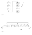
- Fig.1 shows in one embodiment a flow-chart of a method for upscaling an input image X LR t 0 to obtain an upscaled image X HR t 0 .
- the method 10 comprises initializing an upscaled image X HR t 0 , computing 20 motion information for the input image by comparing it with a second image X LR t 1 , wherein inter-frames correspondences are found, upscaling 30 the input image by interpolation to obtain a coarse upscaled image Y HR t 0 , and upscaling 35 the second image X LR t 1 by interpolation to obtain a coarse upscaled second image Y HR t 1 , low-pass (LP) filtering 40 the input image to obtain a LP filtered input image Y LR t 0 , and low-pass filtering 45 the second image X LR t 1 to obtain a LP filtered second image Y LR t 1 .
- LP low-pass
- Further steps comprise dividing 50 the images into overlapping patches, wherein all patches have equal size, and, for a current patch of the upscaled image X HR t 0 , determining 60 a first patch y LR t 0 in the LP filtered input image Y LR t 0 in a position substantially corresponding to that of the current patch (in-place), a second patch y LR t 1 in the LP filtered second image Y LR t 1 in a position that, according to said motion information, corresponds to that the first patch y LR t 0 , a third patch y HR t 0 in the coarse upscaled image Y HR t 1 at a position substantially corresponding to that of the first patch y LR t 0 (in-place), and a fourth patch y HR t 1 in the coarse upscaled second image Y HR t 1 at a position substantially corresponding to that of the second patch y LR t 1 (in-place) ; applying 70 a trained
- the invention performs for both a low-frequency (LF) estimation of the output by an interpolation method (e.g. bicubic).
- the invention computes a motion estimator to find inter-frames correspondences between pixels. By this estimator, for each patch its inter-frame correspondence is found. Then, it is possible to find for both images the in-place matches extracted from the relation between the LR input and the HR coarse estimation previously computed. With this set of patches extracted from the single input patch, a previously trained linear mapping function is then found that corresponds to them, thus estimating the desired output patch through simple matrix multiplication.
- a selector can be applied to find the best estimate between in-place examples and intra-frame examples.
- the linear mapping function is found in offline training.
- an apparatus 100 for upscaling an input image X LR t 0 comprises means 110 being adapted for initializing an upscaled image X HR t 0 , means 120 being adapted for computing motion information for the input image by comparing it with a second image X LR t 1 , wherein inter-frames correspondences are found, means 130 being adapted for upscaling the input image by interpolation to obtain a coarse upscaled image Y HR t 0 , and upscaling 135 the second image X LR t 1 by interpolation to obtain a coarse upscaled second image Y HR t 1 , filtering means 140 being adapted for low-pass filtering the input image to obtain a LP filtered input image Y LR t 0 , and filtering means 145 being adapted for low-pass filtering the second image X LR t 1 to obtain a LP filtered second image Y
- the apparatus 100 further comprises a controller 105 being a module adapted for controlling some or all of the other modules.
- One advantage of the above-described method and apparatus is that searching for a similar patch is reduced to a minimum, due to in-place patch selection.
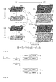
- Fig.3 shows an overview of used images and patches.
- a motion estimator e.g. an optical flow method
- image transformations shown in Fig.3 are performed to the input images 310,330: bicubic interpolation to obtain their HR counterpart 321,341, and Gaussian low pass (LP) filtering to obtain their respective LF versions 320,340.
- LP Gaussian low pass
- inter-frame and in-place are found.
- the in-place match is found by dividing the HR patch position by the employed scaling factor. As this value is normally not an integer, also a nearest neighbor search is performed between several (e.g. nine) patches that are closest to the desired LR position.
- the inter-frame match is found by the optical flow mapping function (e.g. motion information) previously estimated. The same nearest neighbor search as in the previous step is done to find an integer patch position.
- Fig.4 shows a training scheme. Both the LR input and the ground truth HR output must be available to perform the mapping function training.
- the training comprises two main steps: partitioning the patch space (e.g. by clustering), and finding the mapping function for each partition (e.g. for each cluster).
- Two scenarios are contemplated: one uses just the in-place scheme, and the other one mixes in-place and inter-frame schemes.
- n features z LR of the training examples are gathered, and a K-SVD algorithm is computed with them.
- the K-SVD output vectors will become the anchor points (or reference members) for each of the space partitions, ie. clusters.
- Fig.4 shows a corresponding training scheme.
- the blocks in Fig.4 constitute the following: Training data 410 are input to data normalization 420 and a K-SVC algorithm 430.
- the K-SVC algorithm 430 provides as its output a partitioning of the patches, resulting in a plurality of partitions 440a,..., 440d (generally, a given number N).
- a mapping function 450a,...,450d is computed and stored as a regressor R 1 ,...,R N .
- the regressor gets an input patch, it applies the respective mapping function to the input patch and provides an output patch.
- Fig.5 shows data reconstruction, in one embodiment.
- the same image transformations are performed as shown above in the data collection chapter.
- To find the associated partition to each input patch we will find the nearest neighbor to z among the learned anchor points for both cases.
- As each partition has a previously trained matrix R we just have to recover the estimate of our super-resolution patch.
- x HR t 0 x LR t 0 + R z HR - z LR
- a find relatives block 510 which provides the relatives to a scheme selector block 520. It selects either in-place mode or inter-frame mode, or both.
- an associated in-place partition is determined 550. E.g., it is a cluster whose representative patch is most similar to the input patch.
- the partition is associated with a mapping function, which may be a matrix.
- the mapping function is applied to the patch 560, e.g. by matrix multiplication, and provides an upscaled patch to a best-match selector block 570.
- an associated inter-frame partition is determined 530.
- this partition is associated with a mapping function, which may be a matrix.
- the mapping function is applied to the patch 540, e.g. by matrix multiplication, and provides an upscaled patch to the best-match selector block 570. If the scheme selector block 520 has selected both modes, the best-match selector block 570 selects the best matching patch, otherwise it selects the only available patch. It outputs 580 the upscaled patch for assembling the upscaled image. When all the patches are obtained, they are just superposed at their original positions and adequately averaged to provide the desired final image output.
- each of the above-mentioned modules may be implemented, individually and independent from the others, as a hardware (HW) module, a software (SW) module or a SW-controlled HW module, wherein the apparatus for denoising comprises at least one HW module.
- HW hardware
- SW software
- SW-controlled HW module SW-controlled HW module
- the trained regressor is applied to both differences, and a best matching high-frequency patch is selected by a supervised learning algorithm.
- One advantage of the invention is the way it handles sub-pixel accuracy. It can handle very well the recovery of fine structures on scenes with horizontal or vertical motion, which cannot be handled by single image super-resolution methods.
- said substantially corresponding positions are determined within a search window around exactly corresponding positions.
- said position is found by dividing a high resolution patch position by a scaling factor and truncating the result to integers, further comprising a nearest neighbor search between nine patches that are adjacent to the resulting position.
- the above-described method further comprises steps of normalizing all patches after the dividing step, storing normalization information, and denormalizing the patches before said adding step, using the stored normalization information.
- the second image is temporally adjacent to the input image in an image sequence.
- the input image and the input image are still images showing a similar but different scene.
- the above-described method further comprises a training phase using LR and corresponding HR training images, the training phase comprising steps of partitioning a patch space for patches of the training images, and determining, for each partition, a mapping function as said trained regressor.
- the partitioning comprises computing clusters using a K-SVD algorithm and normalized training patches.
- patches are of size 5x5 pixels and overlap by 3 pixels in at least one dimension.
- upscaling does not describe a mere mathematical abstraction, but instead denotes information embodied in or carried by a physical medium capable of detection by a machine or apparatus. This term includes recorded or transmitted signals, and should be understood to include conveyance by any form of encoding, including but not limited to pulse code modulation (PCM).
- PCM pulse code modulation
Landscapes
- Physics & Mathematics (AREA)
- General Physics & Mathematics (AREA)
- Engineering & Computer Science (AREA)
- Theoretical Computer Science (AREA)
- Image Processing (AREA)
Abstract
Image upscaling by super-resolution based on self-similarity can be improved by including a similar image. In particular, motion information providing a relationship between an image to be upscaled and a similar image can be used to easily extend self-similarity to the similar image.
Description
- This invention relates to a method for upscaling an image and apparatus for upscaling an image.
- Freeman et al. [Freeman] started to exploit multi-scale self-example relationship of an image. They generate a dictionary of low-resolution (LR) and high-resolution (HR) patch pairs from an image database to create plausible information for other images with a Markov network type algorithm that abuse the HR-LR patch relation, and an HR neighbor relationship between patches provided by the overlapping patch scheme selection. This scheme has a main issue, it requires an enormous quantity of patch-pairs to generate the desired dictionary, and therefore, it becomes computational expensive.
- Yang et al. [Yang] introduced the usage of dictionaries to find a compact representation of the data for LR-HR patch pairs to capture the co-occurrence prior using sparse signal segmentation in the generation of dictionaries. The main idea is to enforce image patch pairs to have the same sparse representations over both LR and HR dictionaries. Sparse dictionaries have to be jointly learned, because the same sparse representation is needed to represent the low and high resolution patches in their corresponding dictionaries.
- The present invention is based on the recognition of the fact that image upscaling by super-resolution based on self-similarity can be improved by including a similar image.
- In particular, motion information providing a relationship between an image to be upscaled and a similar image can be used to easily extend self-similarity to the similar image.
- According to an embodiment of the invention, a method for upscaling an input image comprises initializing an upscaled image


for a current patch of the upscaled image


a second patch


a third patch


a fourth patch
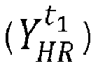

applying (70) a trained regressor (R(zHR-zLR)) to one of:


wherein a high-frequency patch is obtained; and adding (80) the obtained high-frequency patch to a fifth patch


- An apparatus for upscaling an image, in one embodiment, is disclosed in claim 11.
- In one embodiment, the invention relates to a non-transitory computer readable storage medium having stored thereon executable instructions to cause a computer to perform a method for upscaling an image as disclosed above.
- Advantageous embodiments of the invention are disclosed in the dependent claims, the following description and the figures.
- Exemplary embodiments of the invention are described with reference to the accompanying drawings, which show in
-
Fig.1 a flow-chart of a method for upscaling an image; -
Fig.2 a block diagram of an apparatus for upscaling an image; -
Fig.3 an overview of used images and patches; -
Fig.4 a training scheme; and -
Fig.5 an image upscaling scheme. - The goal of image super-resolution (SR) is to perform a transformation of an input low-resolution (LR) patch to a high-resolution (HR) version thereof, by recovering as much as possible of the lost high resolution information.
-
Fig.1 shows in one embodiment a flow-chart of a method for upscaling an input image

method 10 comprises initializing an upscaled image


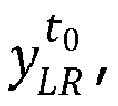
a third patch


a fourth patch


applying 70 a trained regressor R(zHR-zLR) to one of: - (in the case of


- (in the case of


- Parting from the pair of input images, the invention performs for both a low-frequency (LF) estimation of the output by an interpolation method (e.g. bicubic). The invention computes a motion estimator to find inter-frames correspondences between pixels. By this estimator, for each patch its inter-frame correspondence is found. Then, it is possible to find for both images the in-place matches extracted from the relation between the LR input and the HR coarse estimation previously computed. With this set of patches extracted from the single input patch, a previously trained linear mapping function is then found that corresponds to them, thus estimating the desired output patch through simple matrix multiplication. For further improvements, also a selector can be applied to find the best estimate between in-place examples and intra-frame examples. The linear mapping function is found in offline training.
- With the invention it is possible to recover HR patches from self-examples and from inter-frame examples. Thus, due to usage of sub-pixel accuracy information, it is possible to reduce artifacts that cannot be handled via regular single image SR approaches. Thus, the performance of SR is improved.
-
Fig.2 shows a block diagram of an apparatus for upscaling an image. In one embodiment, anapparatus 100 for upscaling an input image
means 110 being adapted for initializing an upscaled image
means 120 being adapted for computing motion information for the input image by comparing it with a second image
means 130 being adapted for upscaling the input image by interpolation to obtain a coarse upscaled image


filtering means 140 being adapted for low-pass filtering the input image to obtain a LP filtered input image


means 160 being adapted for determining, for a current patch of the upscaled image
a first patch

a second patch


a third patch


a fourth patch


means 170 being adapted for applying a trained regressor R(zHR-zLR) to one of: - (in the case of


- (in the case of


- In one embodiment, the
apparatus 100 further comprises acontroller 105 being a module adapted for controlling some or all of the other modules. - One advantage of the above-described method and apparatus is that searching for a similar patch is reduced to a minimum, due to in-place patch selection.
- For easier explanation, the algorithm is separated into three phases: data collection, training, and data reconstruction.
Fig.3 shows an overview of used images and patches.
For data collection, a motion estimator (e.g. an optical flow method) is performed between the two input images 310,330 in order to derive an inter-frame matching function. For example, any conventional motion estimation can be used. Further, image transformations shown inFig.3 are performed to the input images 310,330: bicubic interpolation to obtain their HR counterpart 321,341, and Gaussian low pass (LP) filtering to obtain their respective LF versions 320,340. - For each output patch location, their matches both inter-frame and in-place are found. We will call this group of patches "patch relatives" herein.
The in-place match is found by dividing the HR patch position by the employed scaling factor. As this value is normally not an integer, also a nearest neighbor search is performed between several (e.g. nine) patches that are closest to the desired LR position.
The inter-frame match is found by the optical flow mapping function (e.g. motion information) previously estimated. The same nearest neighbor search as in the previous step is done to find an integer patch position. -
Fig.4 shows a training scheme. Both the LR input and the ground truth HR output must be available to perform the mapping function training. The training comprises two main steps: partitioning the patch space (e.g. by clustering), and finding the mapping function for each partition (e.g. for each cluster).
For partitioning the patch space, a regression function R is used that operates according to
0 .
For the mixed case, z is a patch obtained from both the current input image and a second input image denoted by t1 , according to z = [y t0 ;y t1 ], where the semicolon operator means a concatenation of the vectorized patches. - In one embodiment to perform the space partition, n features zLR of the training examples (that may previously be normalized) are gathered, and a K-SVD algorithm is computed with them. The K-SVD output vectors will become the anchor points (or reference members) for each of the space partitions, ie. clusters.
To fill these space partitions with data, a K-nearest neighbor search with k=1300 for each anchor point will then be performed with the training features, in one embodiment. After having obtained each neighborhood, the following equation is applied to find the mapping matrix:

-
Fig.4 shows a corresponding training scheme. The blocks inFig.4 constitute the following:Training data 410 are input todata normalization 420 and a K-SVC algorithm 430. The K-SVC algorithm 430 provides as its output a partitioning of the patches, resulting in a plurality ofpartitions 440a,..., 440d (generally, a given number N). For each partition, amapping function 450a,...,450d is computed and stored as a regressor R1,...,RN. When the regressor gets an input patch, it applies the respective mapping function to the input patch and provides an output patch. -
Fig.5 shows data reconstruction, in one embodiment. For each image, the same image transformations are performed as shown above in the data collection chapter. We will then, from the HR LF image, partition the image in overlapping 3x3 patches (or similar size), and obtain the relatives of each patch as previously explained. We will then divide the analysis into two branches, an in-place branch and an in-place/inter-frame mixed branch, where the only difference is the definition of z. It is as explained in the training process, and the matrix previously learned is used. To find the associated partition to each input patch, we will find the nearest neighbor to z among the learned anchor points for both cases. As each partition has a previously trained matrix R, we just have to recover the estimate of our super-resolution patch.
- Having obtained both estimated patches, we then perform a selection of the best match with an offline selector previously trained with a Supervised learning algorithm. It could be adaptive boosting (AdaBoost), for instance.
The final scheme can be seen inFig.5 . The meaning of the blocks inFig.5 is as follows: input patches are provided to a find relatives block 510, which provides the relatives toascheme selector block 520. It selects either in-place mode or inter-frame mode, or both. In the case of in-place mode, an associated in-place partition is determined 550. E.g., it is a cluster whose representative patch is most similar to the input patch. As described above, the partition is associated with a mapping function, which may be a matrix. The mapping function is applied to thepatch 560, e.g. by matrix multiplication, and provides an upscaled patch to a best-match selector block 570. On the other hand, if inter-frame mode is selected, an associated inter-frame partition is determined 530. Also this partition is associated with a mapping function, which may be a matrix. The mapping function is applied to thepatch 540, e.g. by matrix multiplication, and provides an upscaled patch to the best-match selector block 570. If thescheme selector block 520 has selected both modes, the best-match selector block 570 selects the best matching patch, otherwise it selects the only available patch. It outputs 580 the upscaled patch for assembling the upscaled image. When all the patches are obtained, they are just superposed at their original positions and adequately averaged to provide the desired final image output. - It is noted that each of the above-mentioned modules may be implemented, individually and independent from the others, as a hardware (HW) module, a software (SW) module or a SW-controlled HW module, wherein the apparatus for denoising comprises at least one HW module.
- In an embodiment of the above-described
method 100, the trained regressor is applied to both differences, and a best matching high-frequency patch is selected by a supervised learning algorithm. - One advantage of the invention is the way it handles sub-pixel accuracy. It can handle very well the recovery of fine structures on scenes with horizontal or vertical motion, which cannot be handled by single image super-resolution methods.
- In an embodiment of the above-described method, said substantially corresponding positions are determined within a search window around exactly corresponding positions.
In an embodiment of the above-described method, said position is found by dividing a high resolution patch position by a scaling factor and truncating the result to integers, further comprising a nearest neighbor search between nine patches that are adjacent to the resulting position.
In an embodiment, the above-described method further comprises steps of normalizing all patches after the dividing step, storing normalization information, and denormalizing the patches before said adding step, using the stored normalization information.
In an embodiment, the second image is temporally adjacent to the input image in an image sequence.
In an embodiment, the input image and the input image are still images showing a similar but different scene.
In an embodiment, the above-described method further comprises a training phase using LR and corresponding HR training images, the training phase comprising steps of partitioning a patch space for patches of the training images, and determining, for each partition, a mapping function as said trained regressor.
In an embodiment, the partitioning comprises computing clusters using a K-SVD algorithm and normalized training patches. - In an embodiment, patches are of size 5x5 pixels and overlap by 3 pixels in at least one dimension.
- The use of the verb "comprise" and its conjugations herein does not exclude the presence of elements or steps other than those stated in a claim. Furthermore, the use of the article "a" or "an" preceding an element does not exclude the presence of a plurality of such elements. "Modules" may be hardware or software items. Several "means" or "modules" may be represented by the same item of hardware or software. Furthermore, the invention resides in each and every novel feature or combination of features.
- The term "upscaling" as used herein does not describe a mere mathematical abstraction, but instead denotes information embodied in or carried by a physical medium capable of detection by a machine or apparatus. This term includes recorded or transmitted signals, and should be understood to include conveyance by any form of encoding, including but not limited to pulse code modulation (PCM).
- While there has been shown, described, and pointed out fundamental novel features of the present invention as applied to preferred embodiments thereof, it will be understood that various omissions and substitutions and changes in the apparatus and method described, in the form and details of the devices disclosed, and in their operation, may be made by those skilled in the art, within the scope of the present invention. It is expressly intended that all combinations of those elements that perform substantially the same function in substantially the same way to achieve the same results are within the scope of the invention. Substitutions of elements from one described embodiment to another are also fully intended and contemplated. It will be understood that the present invention has been described purely by way of example, and modifications of detail can be made within the scope of the invention. Each feature disclosed in the description and the claims and drawings may be provided independently or in any appropriate combination. Features may, where appropriate be implemented in hardware, software, or a combination of the two. Connections may, where applicable, be implemented as wireless connections or wired, not necessarily direct or dedicated, connections. Reference numerals appearing in the claims are by way of illustration only and shall have no limiting effect on the scope of the claims.
-
- [Freeman] "Example-Based Super-Resolution", William T. Freeman, Thouis R. Jones, and Egon C. Pasztor Mitsubishi Electric Research Labs
- [Yang] "Image super resolution via sparse representation", J. Yang, J. Wright, T. Huang, and Y. Ma


Claims (14)
- A method (10) for upscaling an input image

 - initializing an upscaled image
 - computing (20) motion information for the input image by comparing it with a second image
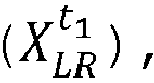 - upscaling (30) the input image by interpolation to obtain a coarse upscaled image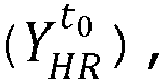

 - low-pass filtering (40) the input image to obtain a LP filtered input image

 - dividing (50) the imagesfor a current patch of the upscaled image
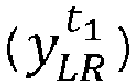
 - determining (60) a first patch


a fourth patch

 - applying (70) a trained regressor (R(zHR-zLR)) to one of:-

 -wherein a high-frequency patch is obtained; and

 - adding (80) the obtained high-frequency patch to a fifth patch


- The method according to claim 1, wherein the trained regressor is applied to both differences, and a best matching high-frequency patch is selected by a supervised learning algorithm.
- The method according to claim 1 or 2, wherein said substantially corresponding positions are determined within a search window around exactly corresponding positions.
- The method according to claim 3, wherein said position is found by dividing a high resolution patch position by a scaling factor and truncating the result to integers, further comprising a nearest neighbor search between nine patches that are adjacent to the resulting position.
- The method according to one of the claims 1-4, further comprising steps of- normalizing all patches after the dividing step;- storing normalization information; and- denormalizing the patches before said adding step, using the stored normalization information.
- The method according to one of the claims 1-5, wherein the second image is temporally adjacent to the input image in an image sequence.
- The method according to one of the claims 1-6, wherein the input image and the input image are still images showing a different scene.
- The method according to one of the claims 1-7, further comprising a training phase using LR and corresponding HR training images, the training phase comprising steps of- partitioning a patch space for patches of the training images; and- determining, for each partition, a mapping function as said trained regressor.
- The method according to claim 8, wherein the partitioning comprises computing clusters using a K-SVD algorithm and normalized training patches.
- The method according to any of the claims 1-9, wherein patches are of size 5x5 pixels and overlap by 3 pixels in at least one dimension.
- An apparatus for upscaling an image, comprising a processor and a memory storing instructions that, when executed by the processor, cause the processor to perform a method according to any of the claims 1-10.
- An apparatus (100) for upscaling an input image
 - means (110) being adapted for initializing an upscaled image
 - means (120) being adapted for computing motion information for the input image by comparing it with a second image
 - means (130) being adapted for upscaling the input image by interpolation to obtain a coarse upscaled image

 - filtering means (140) being adapted for low-pass filtering the input image to obtain a LP filtered input image

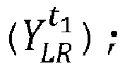 - means (150) being adapted for dividing the images
 - means (160) being adapted for determining, for a current patch of the upscaled image
a first patch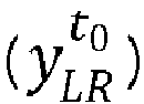

a second patch


a fourth patch

 - means (170) being adapted for applying a trained regressor (R(zHR-zLR)) to one of:-

 -
-

 - means (180) being adapted for adding the obtained high-frequency patch to a fifth patch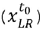


- The apparatus according to claim 12, wherein the trained regressor is applied to both differences, further comprising a supervised learning module being adapted for selecting a best matching high-frequency patch.
- A non-transitory computer readable storage medium having stored thereon executable instructions to cause a computer to perform a method for upscaling an input image
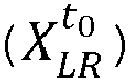
 - initializing an upscaled image
 - computing (20) motion information for the input image by comparing it with a second image
 - upscaling (30) the input image by interpolation to obtain a coarse upscaled image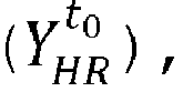

 - low-pass filtering (40) the input image to obtain a LP filtered input image
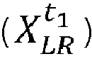
 - dividing (50) the imagesfor a current patch of the upscaled image
 - determining a first patch

a second patch


a fourth patch

 - applying a trained regressor (R(zHR-zLR)) to one of:-

 -
-

 - adding the obtained high-frequency patch to a fifth patch


Priority Applications (1)
| Application Number | Priority Date | Filing Date | Title |
|---|---|---|---|
| EP15306772.3A EP3166069A1 (en) | 2015-11-06 | 2015-11-06 | Method for denoising an image and apparatus for upscaling an image |
Applications Claiming Priority (1)
| Application Number | Priority Date | Filing Date | Title |
|---|---|---|---|
| EP15306772.3A EP3166069A1 (en) | 2015-11-06 | 2015-11-06 | Method for denoising an image and apparatus for upscaling an image |
Publications (1)
| Publication Number | Publication Date |
|---|---|
| EP3166069A1 true EP3166069A1 (en) | 2017-05-10 |
Family
ID=54608465
Family Applications (1)
| Application Number | Title | Priority Date | Filing Date |
|---|---|---|---|
| EP15306772.3A Withdrawn EP3166069A1 (en) | 2015-11-06 | 2015-11-06 | Method for denoising an image and apparatus for upscaling an image |
Country Status (1)
| Country | Link |
|---|---|
| EP (1) | EP3166069A1 (en) |
Cited By (2)
| Publication number | Priority date | Publication date | Assignee | Title |
|---|---|---|---|---|
| WO2019055822A1 (en) * | 2017-09-15 | 2019-03-21 | Snap Inc. | Real-time tracking compensated image effects |
| CN115115553A (en) * | 2022-08-26 | 2022-09-27 | 华伦医疗用品(深圳)有限公司 | Endoscope image noise reduction processing method, electronic equipment and system |
Citations (6)
| Publication number | Priority date | Publication date | Assignee | Title |
|---|---|---|---|---|
| US20050232514A1 (en) * | 2004-04-15 | 2005-10-20 | Mei Chen | Enhancing image resolution |
| US20130034271A1 (en) * | 2011-06-24 | 2013-02-07 | Satoshi Sakaguchi | Super-resolution processor and super-resolution processing method |
| EP2662824A1 (en) * | 2012-05-10 | 2013-11-13 | Thomson Licensing | Method and device for generating a super-resolution version of a low resolution input data structure |
| WO2014114635A1 (en) * | 2013-01-24 | 2014-07-31 | Thomson Licensing | Method and apparatus for performing super-resolution of single images |
| WO2014174030A1 (en) * | 2013-04-25 | 2014-10-30 | Thomson Licensing | Method and device for performing super-resolution on an input image |
| WO2014174087A1 (en) * | 2013-04-25 | 2014-10-30 | Thomson Licensing | Method and device for performing super-resolution on an input image |
-
2015
- 2015-11-06 EP EP15306772.3A patent/EP3166069A1/en not_active Withdrawn
Patent Citations (6)
| Publication number | Priority date | Publication date | Assignee | Title |
|---|---|---|---|---|
| US20050232514A1 (en) * | 2004-04-15 | 2005-10-20 | Mei Chen | Enhancing image resolution |
| US20130034271A1 (en) * | 2011-06-24 | 2013-02-07 | Satoshi Sakaguchi | Super-resolution processor and super-resolution processing method |
| EP2662824A1 (en) * | 2012-05-10 | 2013-11-13 | Thomson Licensing | Method and device for generating a super-resolution version of a low resolution input data structure |
| WO2014114635A1 (en) * | 2013-01-24 | 2014-07-31 | Thomson Licensing | Method and apparatus for performing super-resolution of single images |
| WO2014174030A1 (en) * | 2013-04-25 | 2014-10-30 | Thomson Licensing | Method and device for performing super-resolution on an input image |
| WO2014174087A1 (en) * | 2013-04-25 | 2014-10-30 | Thomson Licensing | Method and device for performing super-resolution on an input image |
Non-Patent Citations (2)
| Title |
|---|
| J. YANG; J. WRIGHT; T. HUANG; Y. MA, IMAGE SUPER RESOLUTION VIA SPARSE REPRESENTATION |
| WILLIAM T. FREEMAN; THOUIS R. JONES; EGON C, EXAMPLE-BASED SUPER-RESOLUTION |
Cited By (6)
| Publication number | Priority date | Publication date | Assignee | Title |
|---|---|---|---|---|
| WO2019055822A1 (en) * | 2017-09-15 | 2019-03-21 | Snap Inc. | Real-time tracking compensated image effects |
| US10474900B2 (en) | 2017-09-15 | 2019-11-12 | Snap Inc. | Real-time tracking-compensated image effects |
| US10929673B2 (en) | 2017-09-15 | 2021-02-23 | Snap Inc. | Real-time tracking-compensated image effects |
| US11676381B2 (en) | 2017-09-15 | 2023-06-13 | Snap Inc. | Real-time tracking-compensated image effects |
| US11989938B2 (en) | 2017-09-15 | 2024-05-21 | Snap Inc. | Real-time tracking-compensated image effects |
| CN115115553A (en) * | 2022-08-26 | 2022-09-27 | 华伦医疗用品(深圳)有限公司 | Endoscope image noise reduction processing method, electronic equipment and system |
Similar Documents
| Publication | Publication Date | Title |
|---|---|---|
| CN113014927B (en) | Image compression method and image compression device | |
| Lu et al. | Geometry constrained sparse coding for single image super-resolution | |
| Lin et al. | Cascaded feature network for semantic segmentation of RGB-D images | |
| JP6192670B2 (en) | Method and apparatus for performing hierarchical super-resolution of input images | |
| Li et al. | Video super-resolution using an adaptive superpixel-guided auto-regressive model | |
| US12561755B2 (en) | System and method for image super-resolution | |
| KR20190114340A (en) | Image deblurring network processing methods and systems | |
| CN112070670A (en) | Face super-resolution method and system of global-local separation attention mechanism | |
| CN104160422A (en) | Method and apparatus for performing super-resolution | |
| US20200057921A1 (en) | Image classification and conversion method and device, image processor and training method therefor, and medium | |
| WO2017110836A1 (en) | Method and system for fusing sensed measurements | |
| EP2680226B1 (en) | Temporally consistent superpixels | |
| WO2014114635A1 (en) | Method and apparatus for performing super-resolution of single images | |
| Dai et al. | Dictionary-based multiple frame video super-resolution | |
| CN109685830B (en) | Target tracking method, device and equipment and computer storage medium | |
| KR20160115925A (en) | Method and device for enhancing quality of an image | |
| CN114730455A (en) | Plausible day scale delay generation method and computing device | |
| Haq et al. | Dynamic mode decomposition via dictionary learning for foreground modeling in videos | |
| Ye et al. | Depth super-resolution via deep controllable slicing network | |
| Yokota et al. | Tensor completion with shift-invariant cosine bases | |
| KR20120088350A (en) | Apparatus for generating high resolution image | |
| Zhang et al. | Joint deep-unfolding optimization learning for depth map arbitrary-scale super-resolution | |
| CN115731447B (en) | Decompressed image object detection method and system based on attention mechanism distillation | |
| Zhang et al. | Medical image super-resolution with non-local embedding sparse representation and improved IBP | |
| Luo et al. | Piecewise linear regression-based single image super-resolution via Hadamard transform |
Legal Events
| Date | Code | Title | Description |
|---|---|---|---|
| PUAI | Public reference made under article 153(3) epc to a published international application that has entered the european phase |
Free format text: ORIGINAL CODE: 0009012 |
|
| AK | Designated contracting states |
Kind code of ref document: A1 Designated state(s): AL AT BE BG CH CY CZ DE DK EE ES FI FR GB GR HR HU IE IS IT LI LT LU LV MC MK MT NL NO PL PT RO RS SE SI SK SM TR |
|
| AX | Request for extension of the european patent |
Extension state: BA ME |
|
| STAA | Information on the status of an ep patent application or granted ep patent |
Free format text: STATUS: THE APPLICATION IS DEEMED TO BE WITHDRAWN |
|
| 18D | Application deemed to be withdrawn |
Effective date: 20171111 |