EP3165854A1 - Cryogen injection apparatus and corresponding method - Google Patents
Cryogen injection apparatus and corresponding method Download PDFInfo
- Publication number
- EP3165854A1 EP3165854A1 EP16155127.0A EP16155127A EP3165854A1 EP 3165854 A1 EP3165854 A1 EP 3165854A1 EP 16155127 A EP16155127 A EP 16155127A EP 3165854 A1 EP3165854 A1 EP 3165854A1
- Authority
- EP
- European Patent Office
- Prior art keywords
- heat transfer
- nozzle
- housing
- fluid
- blender
- Prior art date
- Legal status (The legal status is an assumption and is not a legal conclusion. Google has not performed a legal analysis and makes no representation as to the accuracy of the status listed.)
- Withdrawn
Links
- 238000002347 injection Methods 0.000 title claims abstract description 67
- 239000007924 injection Substances 0.000 title claims abstract description 67
- 238000000034 method Methods 0.000 title claims abstract description 15
- 239000013529 heat transfer fluid Substances 0.000 claims abstract description 35
- 238000012546 transfer Methods 0.000 claims abstract description 32
- 239000012530 fluid Substances 0.000 claims abstract description 19
- 239000000126 substance Substances 0.000 claims abstract description 13
- 238000004891 communication Methods 0.000 claims abstract description 9
- XLYOFNOQVPJJNP-UHFFFAOYSA-N water Substances O XLYOFNOQVPJJNP-UHFFFAOYSA-N 0.000 claims description 18
- -1 steam Substances 0.000 claims description 5
- 239000000463 material Substances 0.000 claims description 4
- 238000010257 thawing Methods 0.000 claims description 3
- 238000010792 warming Methods 0.000 claims description 3
- 230000000717 retained effect Effects 0.000 claims description 2
- IJGRMHOSHXDMSA-UHFFFAOYSA-N Atomic nitrogen Chemical compound N#N IJGRMHOSHXDMSA-UHFFFAOYSA-N 0.000 description 30
- 239000007788 liquid Substances 0.000 description 16
- 235000013305 food Nutrition 0.000 description 15
- 229910052757 nitrogen Inorganic materials 0.000 description 15
- 229910001220 stainless steel Inorganic materials 0.000 description 8
- 239000010935 stainless steel Substances 0.000 description 8
- 235000013372 meat Nutrition 0.000 description 5
- 238000010276 construction Methods 0.000 description 3
- 238000001816 cooling Methods 0.000 description 3
- 239000007789 gas Substances 0.000 description 3
- 229910000831 Steel Inorganic materials 0.000 description 2
- 238000004140 cleaning Methods 0.000 description 2
- 239000012459 cleaning agent Substances 0.000 description 2
- 230000008602 contraction Effects 0.000 description 2
- 230000001419 dependent effect Effects 0.000 description 2
- 239000004615 ingredient Substances 0.000 description 2
- 238000002156 mixing Methods 0.000 description 2
- 239000000203 mixture Substances 0.000 description 2
- 238000012986 modification Methods 0.000 description 2
- 230000004048 modification Effects 0.000 description 2
- 239000000243 solution Substances 0.000 description 2
- 239000007921 spray Substances 0.000 description 2
- 239000010959 steel Substances 0.000 description 2
- 229910001369 Brass Inorganic materials 0.000 description 1
- RYGMFSIKBFXOCR-UHFFFAOYSA-N Copper Chemical compound [Cu] RYGMFSIKBFXOCR-UHFFFAOYSA-N 0.000 description 1
- 239000004809 Teflon Substances 0.000 description 1
- 229920006362 Teflon® Polymers 0.000 description 1
- 239000010951 brass Substances 0.000 description 1
- 239000010949 copper Substances 0.000 description 1
- 229910052802 copper Inorganic materials 0.000 description 1
- 238000005336 cracking Methods 0.000 description 1
- 238000002788 crimping Methods 0.000 description 1
- 230000007812 deficiency Effects 0.000 description 1
- 230000000694 effects Effects 0.000 description 1
- 235000012041 food component Nutrition 0.000 description 1
- 238000007710 freezing Methods 0.000 description 1
- 230000008014 freezing Effects 0.000 description 1
- 235000013611 frozen food Nutrition 0.000 description 1
- 235000020993 ground meat Nutrition 0.000 description 1
- 238000010438 heat treatment Methods 0.000 description 1
- 238000013508 migration Methods 0.000 description 1
- 230000005012 migration Effects 0.000 description 1
- 239000004033 plastic Substances 0.000 description 1
- 230000008569 process Effects 0.000 description 1
- 238000012545 processing Methods 0.000 description 1
Images


Classifications
-
- A—HUMAN NECESSITIES
- A23—FOODS OR FOODSTUFFS; TREATMENT THEREOF, NOT COVERED BY OTHER CLASSES
- A23G—COCOA; COCOA PRODUCTS, e.g. CHOCOLATE; SUBSTITUTES FOR COCOA OR COCOA PRODUCTS; CONFECTIONERY; CHEWING GUM; ICE-CREAM; PREPARATION THEREOF
- A23G9/00—Frozen sweets, e.g. ice confectionery, ice-cream; Mixtures therefor
- A23G9/04—Production of frozen sweets, e.g. ice-cream
- A23G9/22—Details, component parts or accessories of apparatus insofar as not peculiar to a single one of the preceding groups
- A23G9/228—Arrangement and mounting of control or safety devices
-
- A—HUMAN NECESSITIES
- A23—FOODS OR FOODSTUFFS; TREATMENT THEREOF, NOT COVERED BY OTHER CLASSES
- A23B—PRESERVATION OF FOODS, FOODSTUFFS OR NON-ALCOHOLIC BEVERAGES; CHEMICAL RIPENING OF FRUIT OR VEGETABLES
- A23B2/00—Preservation of foods or foodstuffs, in general
- A23B2/80—Freezing; Subsequent thawing; Cooling
-
- A—HUMAN NECESSITIES
- A23—FOODS OR FOODSTUFFS; TREATMENT THEREOF, NOT COVERED BY OTHER CLASSES
- A23B—PRESERVATION OF FOODS, FOODSTUFFS OR NON-ALCOHOLIC BEVERAGES; CHEMICAL RIPENING OF FRUIT OR VEGETABLES
- A23B2/00—Preservation of foods or foodstuffs, in general
- A23B2/80—Freezing; Subsequent thawing; Cooling
- A23B2/85—Freezing; Subsequent thawing; Cooling with addition of or treatment with chemicals
- A23B2/88—Freezing; Subsequent thawing; Cooling with addition of or treatment with chemicals with direct contact between the food and the chemical, e.g. liquid N2 at cryogenic temperature
-
- B—PERFORMING OPERATIONS; TRANSPORTING
- B05—SPRAYING OR ATOMISING IN GENERAL; APPLYING FLUENT MATERIALS TO SURFACES, IN GENERAL
- B05B—SPRAYING APPARATUS; ATOMISING APPARATUS; NOZZLES
- B05B1/00—Nozzles, spray heads or other outlets, with or without auxiliary devices such as valves, heating means
- B05B1/24—Nozzles, spray heads or other outlets, with or without auxiliary devices such as valves, heating means incorporating means for heating the liquid or other fluent material, e.g. electrically
-
- F—MECHANICAL ENGINEERING; LIGHTING; HEATING; WEAPONS; BLASTING
- F25—REFRIGERATION OR COOLING; COMBINED HEATING AND REFRIGERATION SYSTEMS; HEAT PUMP SYSTEMS; MANUFACTURE OR STORAGE OF ICE; LIQUEFACTION SOLIDIFICATION OF GASES
- F25D—REFRIGERATORS; COLD ROOMS; ICE-BOXES; COOLING OR FREEZING APPARATUS NOT OTHERWISE PROVIDED FOR
- F25D3/00—Devices using other cold materials; Devices using cold-storage bodies
- F25D3/10—Devices using other cold materials; Devices using cold-storage bodies using liquefied gases, e.g. liquid air
-
- A—HUMAN NECESSITIES
- A23—FOODS OR FOODSTUFFS; TREATMENT THEREOF, NOT COVERED BY OTHER CLASSES
- A23V—INDEXING SCHEME RELATING TO FOODS, FOODSTUFFS OR NON-ALCOHOLIC BEVERAGES AND LACTIC OR PROPIONIC ACID BACTERIA USED IN FOODSTUFFS OR FOOD PREPARATION
- A23V2002/00—Food compositions, function of food ingredients or processes for food or foodstuffs
Definitions
- the present invention relates to injection of cryogen into blenders or mixers for cooling, and more particularly to nozzle apparatus that introduce cryogenic substances into products, especially into food products, for chilling and/or freezing same.
- cryogen into mixers for cooling food products for example
- Such known bottom injection nozzles for cryogenic substances such as for example liquid nitrogen (LIN)
- LIN liquid nitrogen
- nozzles are manufactured with a teflon sleeve which reduces the amount of heat transfer from the blender wall to the nozzle, but such nozzles are susceptible to migration of the food product between the sleeve and the housing and will therefore crack the nozzle due to thermal expansion and contraction from the cryogenic substance.
- an object of the present invention is to overcome the limitations and problems that earlier apparatus and methods have experienced.
- the present invention basically provides for a liquid cryogen, in particular liquid nitrogen (LIN), injection nozzle apparatus which is not clogged from use of the cryogenic substance, in particular of the liquid nitrogen (LIN).
- a liquid cryogen in particular liquid nitrogen (LIN)
- injection nozzle apparatus which is not clogged from use of the cryogenic substance, in particular of the liquid nitrogen (LIN).
- a cryogen injection apparatus for injecting a cryogenic substance into a blender or mixer, which includes at least one nozzle constructed for being in fluid communication with an interior of the blender or mixer; a heat transfer fluid for being operationally associated by conduction with the at least one nozzle; and a heat transfer housing supporting the at least one nozzle and having a space therein for receipt of the heat transfer fluid to warm the at least one nozzle.
- the heat transfer housing in particular the heat sink member, may comprise an enclosure having an, in particular spiral, fin at the space for providing an, in particular continuous, flow path for the heat transfer fluid in the space.
- a higher velocity of the heat transfer fluid through the path provides for an increase in heat transfer between the wall of the mixer or blender and the heat transfer housing.
- a block housing or block member may be used to contain and direct the flow of the heat transfer fluid to the heat transfer housing, in particular to the heat sink member, and through the spiral path.
- the block housing or block member may favourably comprise a first open end sized and shaped to receive the heat transfer housing, in particular to the heat sink member, therein to restrict the heat transfer fluid to said flow path.
- an outer cover or outer housing may retain the heat transfer housing, in particular the heat sink member, and the flow block housing or flow block member as being releasably mounted together and protects the injection nozzle from external pressure water sprays and cleaning agents.
- Said outer cover or outer housing may comprise a second open end sized and shaped to receive the flow block housing or flow block member therein to protect said flow block housing and said heat transfer housing.
- the heat transfer housing may advantageously comprise an enclosure having a chamber therein, said chamber being expediently in fluid communication with an inlet port and with an outlet port.
- the at least one nozzle may favourably be disposed through said camber, and/or the heat transfer fluid may preferably be releasably retained in said chamber to warm the at least one nozzle.
- the heat transfer housing may advantageously comprise an exterior surface having a shape conforming to an external portion of the blender or mixer for being mounted flush thereto.
- a method for heat transfer of an injection nozzle providing a cryogenic substance to a blender or mixer which includes supporting the injection nozzle at a wall of the blender or mixer for being in communication with an interior of said blender or mixer; and providing heat transfer with a fluid to said injection nozzle.
- the warming may further comprise defrosting any frozen matter within the injection nozzle.
- the heat transfer fluid may be a substance selected from the group consisting of water, steam, air, hot gas, and at least one combination thereof.
- the present embodiments include a low thermal mass straight bore (or expanding bore) nozzle with an integrated heating system which provides for rapid or quick warming or thawing of the nozzle, and therefore clearing of any product within the nozzle between injection cycles of cryogen, such as liquid nitrogen (LIN), from the nozzle.
- cryogen such as liquid nitrogen (LIN)
- the construction of the present nozzle embodiments also eliminates the possibility of cracking of the nozzle because there is no internal sleeve for the nozzle used which could permit thermal expansion and contraction of any frozen product, in particular food product, or condensate between the nozzle body and the thermal sleeve.
- an injection nozzle apparatus of a first embodiment of the present invention is shown generally at 10 mounted to a wall 12 of a blender or mixer (not shown) in which food product (not shown) is disposed for being chilled. While food product is referred to for being treated by the injection nozzle 10, it is understood that other types of products can be treated with the present injection nozzle embodiment.
- the injection nozzle apparatus 10 or apparatus comprises a nozzle or nozzle portion 14, a heat sink member 16, a flow block member 18 and an outer cover or housing 20.
- a mechanical fastener such as for example a nut 21 removably mounts the heat sink member 16 to the nozzle portion 14 as discussed below.
- the nozzle portion 14 delivers a cryogen, such as liquid nitrogen (LIN), into the blender.
- LIN liquid nitrogen
- the nozzle 14 can be either a straight bore stainless steel tube or a machined steel tube with an expanding bore, wherein a diameter of the bore increases along the flow path in the direction of the wall 12.
- the nozzle 14 is constructed from a material that has a low thermal mass.
- the heat sink member 16 is used to transfer heat to the blender wall 12 and the nozzle 14.
- the heat sink member 16 is constructed with a spiral fin 17 for providing a continuous spiral path 19 of the heat sink member 16 as shown for example in FIG. 3 and in FIG. 4A , so that any applied heat transfer fluid 22 must travel through the spiral path 19. A higher velocity of the heat transfer fluid 22 through the spiral path 19 will provide for an increase in heat transfer between the wall 12 and the heat sink member 16.
- the heat transfer fluid 22 is discharged from the heat sink member 16 along an axial orientation of the nozzle 14 and then out of the housing 20. Heat is first transferred into the wall 12 and then to the nozzle 14. A thermal mass of the wall 12 is greater than a thermal mass of the nozzle 14. Therefore, any of the heat transfer fluid 22 with a sufficient temperature and thermal conductivity can be used, such as for example water, steam, air, hot gas, etc.
- the flow block member 18 includes an inlet port 24 and an outlet port 26.
- the housing 20 also includes a inlet port 28 and outlet port 30.
- the inlet ports 24, 28 can be, although do not have to be, in registration with each other, while the outlet ports 26, 30 can be, although do not have to be, in registration with each other to provide for the flow of the heat transfer fluid 22 into the spiral path 19 for providing heat transfer and to ultimately be exhausted from the outlet port 30.
- the flow block member 18 is used to contain and direct the flow of the heat transfer fluid 22 to the heat sink member 16 and through the spiral path 19.
- the housing 20 retains the heat sink member 16 and the flow block member 18 as being releasably mounted together and protects the injection nozzle 10 from external pressure water sprays and cleaning agents.
- the nozzle portion 14 may be constructed from stainless steel; the heat sink member 16 may be constructed from brass, copper or any other material having high thermal conductivity; the flow block member 18 may be constructed from stainless steel or plastic; and the outer cover or housing 20 may be constructed from stainless steel.
- the injection nozzle apparatus 10 of the embodiment shown in FIG. 1 to FIG. 4B permits the nozzle 14 to be easily cleaned, because the only element of the nozzle 14 exposed to an interior of the blender is an interior of the nozzle portion 14. Therefore, hot water or other cleaning solutions can be sprayed through the nozzle portion 14 for easy cleaning without having to disassemble the injection nozzle 10.
- the flow of the heat transfer fluid 22 is as follows:
- the heat transfer fluid 22 is thereafter introduced into the spiral path 19 of the heat sink member 16 which is seated within the flow block 18, for the fluid to move along the spiral path 19 where heat transfer occurs for the nozzle 14 and the wall 12 of the blender. Upon completion of the heat transfer fluid 22 travelling along the spiral path 19, the fluid is directed back into the flow block 18 whereupon the fluid exits the block from the outlet port 26 as shown in FIG. 3 .
- the outlet port of the flow block member 18 may be in registration with the outlet port 30 of the outer cover 20, when the flow block member 18 is seated within the outer cover 20 such that the fluid 22 can be exhausted quickly from the heat sink member 16 and the flow block 18.
- the heat sink member 16, the flow block member 18 and the outer cover 20 each have a corresponding central axial hole 16a, 18a, 20a, respectively, as shown for example in FIG. 3 which, when such elements are mounted to the nozzle 14, are in registration with each other so that the injection nozzle apparatus 10 can be mounted to the wall 12 as shown in FIG. 1 to FIG. 2 .
- the nozzle portion 14 extends through the wall 12 of the blender and has an exterior threaded surface area 15, as shown.
- the nozzle portion 14 is disposed through the central axial hole 16a of the heat sink member 16 and the mechanical fastener, such as the nut 21, is threaded to the threaded area 15 of the nozzle 14.
- the flow block member 18 is seated by friction fit or crimping to the heat sink member 16, and the outer cover 20 may be similarly mounted to the flow block 18.
- An alternate embodiment can have a mechanical fastener 21a, for example a nut, positioned as shown to threadably engage the nozzle portion 14 where it protrudes through the central axial hole 20a of the outer cover 20.
- the nozzle portion 14 has a threaded surface area at that portion protruding from the outer cover.
- the apparatus 10 can be fabricated as a single, integral unit to be mounted to the wall 12 of the blender.
- a batch of food product such as for example ground meat with ingredients therein, is placed in the blender or mixer which is started such that internal blades (not shown) of the blender or mixer mix the food product and ingredients. It is required to chill the meat during the blending operation and therefore, cryogen such as liquid nitrogen (LIN) is injected into the blender or mixer through the injection nozzle 10.
- cryogen such as liquid nitrogen (LIN) is injected into the blender or mixer through the injection nozzle 10.
- liquid nitrogen (LIN) is injected through the nozzle portion 14 during which heat is transferred from the wall 12 via conduction with the nozzle portion 14 which also has its temperature reduced to a temperature substantially similar to that of the liquid nitrogen (LIN).
- Minimal heat is transferred between the wall 12 and the nozzle 14 due to a low thermal mass of the nozzle portion 14.
- injection of the liquid nitrogen (LIN) 15 is stopped and the meat is removed from the blender or mixer.
- the heat transfer fluid 22 is introduced into the inlet port 28 of the outer cover 20 as explained above to rapidly thaw the injection nozzle 14. Any meat or water trapped within the nozzle portion 14 is warmed and can be easily discharged at a start of the next batch of food product being used in the blender.
- the next batch of meat is thereby loaded into the blender and the process continues.
- the construction of the injection nozzle apparatus 10 permits clean-in-place (CIP) of the nozzle portion 14 without removal or disassembly of the apparatus.
- FIG. 5 and to FIG. 6 another embodiment of the injection nozzle apparatus is shown generally at 100 mounted to a wall 102 of a blender or mixer (not shown).
- water is used to defrost or thaw the apparatus 100 and the wall 102 after an injection cycle of liquid nitrogen (LIN) is introduced to the blender.
- LIN liquid nitrogen
- the injection nozzle apparatus 100 includes a housing 104 or enclosure which can be manufactured from stainless steel.
- the housing 104 includes a plurality of sidewalls, one of such sidewall 106 having a surface area substantially conforming to a shape of an exterior surface of the wall 102.
- the sidewall 106 permits the housing 104 to lie flush against an exterior surface 108 of the wall 102.
- the sidewalls of the housing 104 define a space 109 or chamber therein.
- An inlet port 110 is provided at an upper sidewall of the housing 104, while an outlet port 112 is provided at a lower one of the sidewalls of the housing 104.
- a heat transfer fluid 114 such as for example water, is introduced into the inlet port 110 and therefore into the space 109, with the space 109 thus being flooded with water, after which the fluid 114 can be removed from the space 109 through the outlet port 112.
- the sidewalls of the housing 104 may be arranged to provide an extended portion 116 through which at least one cryogen injection nozzle 118 extends and through the space 109 and the wall 102 for opening into the blender where food product 120 is being chilled.
- the extended portion 116 provides a larger volume of the space 109 only where the injection nozzle(s) 118 are disposed so that heat transfer is more thorough, uniform, and occurs more quickly.
- the cryogen may be liquid nitrogen (LIN).
- LIN liquid nitrogen
- FIG. 5 and in FIG. 6 there is a pair of the injection nozzles 118, but it is understood that one or a plurality of the nozzles 118 can be used depending upon the amount of liquid nitrogen (LIN) to be introduced into the blender and the nature or type of the product 120 being processed therein.
- the heat transfer fluid 114 such as water for example, is purged from the space 109 of the housing 104, and a cryogen injection cycle begins having a duration of approximately six to eight minutes, during which occurs liquid nitrogen (LIN) injected through the nozzles 118 to the food product 120 in the blender.
- LIN liquid nitrogen
- the heat transfer fluid 114 in this case water
- the space 109 is introduced into the space 109 from the inlet port 110 at a rate of approximately ten to thirty litres per hour for a period of from six to twelve minutes.
- the water will defrost or thaw the injection nozzle(s) 118 and the surface 108 and wall 102 in close proximity to the sidewall 106. Accordingly, there should be no frozen food product or condensate in the injection nozzle 118.
- any frozen product or moisture in the injection nozzle(s) 118 has been warmed to a temperature sufficient to eject same into the blender at the next LIN injection cycle.
- the water 114 is then purged from the space 109 of the housing 104 and a subsequent cryogen cycle begins.
- the tubing of the injection nozzle 118 or nozzles permits clean-in-place (CIP) of the nozzle 118 without removal of same from the housing 104.
- CIP clean-in-place
- Valving (not shown) operatively associated with the outlet port 112 can be used to retain the heat transfer fluid 114 to a specific depth or amount in the space 109 to carry out the heat transfer effect of the nozzles 118.
Landscapes
- Engineering & Computer Science (AREA)
- Life Sciences & Earth Sciences (AREA)
- Chemical & Material Sciences (AREA)
- Food Science & Technology (AREA)
- Polymers & Plastics (AREA)
- Wood Science & Technology (AREA)
- Zoology (AREA)
- Combustion & Propulsion (AREA)
- Physics & Mathematics (AREA)
- Mechanical Engineering (AREA)
- Thermal Sciences (AREA)
- General Engineering & Computer Science (AREA)
Abstract
In order to overcome the limitations and problems that earlier apparatus and methods have experienced, a cryogen injection apparatus (10; 100) for injecting a cryogenic substance into a blender or mixer is proposed, said apparatus (10; 100) comprising:
- at least one nozzle (14; 118) constructed for being in fluid communication with an interior of the blender or mixer;
- a heat transfer fluid (22; 114) for being operationally associated by conduction with the at least one nozzle (14; 118); and
- a heat transfer housing (16) supporting the at least one nozzle (14; 118) and having a space therein for receipt of the heat transfer fluid (22; 114) to warm the at least one nozzle (14; 118).
- at least one nozzle (14; 118) constructed for being in fluid communication with an interior of the blender or mixer;
- a heat transfer fluid (22; 114) for being operationally associated by conduction with the at least one nozzle (14; 118); and
- a heat transfer housing (16) supporting the at least one nozzle (14; 118) and having a space therein for receipt of the heat transfer fluid (22; 114) to warm the at least one nozzle (14; 118).
A related method is also provided.
Description
- The present invention relates to injection of cryogen into blenders or mixers for cooling, and more particularly to nozzle apparatus that introduce cryogenic substances into products, especially into food products, for chilling and/or freezing same.
- The bottom injection of cryogen into mixers for cooling food products, for example, is known. Such known bottom injection nozzles for cryogenic substances, such as for example liquid nitrogen (LIN), encounter difficulties when being used with wet products which are drawn into an orifice of the nozzle in communication with the food processing equipment, whereupon the wet food product is frozen upon exposure to the cryogen.
- When such a situation occurs, the nozzle orifice will become restricted and eventually clogged. Unfortunately, it is extremely difficult to clear the nozzle, frequently requiring disassembly of same, and no further cooling cryogenic substance can be delivered to the mixer for chilling until the clog is removed.
- Existing nozzle structure contributes to this deficiency. That is, known nozzles are made from either thick stainless steel, which transfers a large amount of heat from the mixture or blender wall and thereafter remains cold after an injection cycle of the cryogen until the mixing is complete. This type of stainless steel nozzle contributes to the clogging situation when the cryogenic substance, such as liquid nitrogen (LIN) for example, is exposed to the wet product in the blender or mixer.
- Other nozzles are manufactured with a teflon sleeve which reduces the amount of heat transfer from the blender wall to the nozzle, but such nozzles are susceptible to migration of the food product between the sleeve and the housing and will therefore crack the nozzle due to thermal expansion and contraction from the cryogenic substance.
- Starting from the disadvantages and shortcomings as described above as well as taking the prior art as discussed into account, an object of the present invention is to overcome the limitations and problems that earlier apparatus and methods have experienced.
- This object is accomplished by an apparatus comprising the features of claim 1 as well as by a method comprising the features of
claim 10. Advantageous embodiments and expedient improvements of the present invention are disclosed in the respective dependent claims. - The present invention basically provides for a liquid cryogen, in particular liquid nitrogen (LIN), injection nozzle apparatus which is not clogged from use of the cryogenic substance, in particular of the liquid nitrogen (LIN).
- There is provided a cryogen injection apparatus for injecting a cryogenic substance into a blender or mixer, which includes at least one nozzle constructed for being in fluid communication with an interior of the blender or mixer; a heat transfer fluid for being operationally associated by conduction with the at least one nozzle; and a heat transfer housing supporting the at least one nozzle and having a space therein for receipt of the heat transfer fluid to warm the at least one nozzle.
- According to an advantageous embodiment of the present invention, the heat transfer housing, in particular the heat sink member, may comprise an enclosure having an, in particular spiral, fin at the space for providing an, in particular continuous, flow path for the heat transfer fluid in the space. A higher velocity of the heat transfer fluid through the path provides for an increase in heat transfer between the wall of the mixer or blender and the heat transfer housing.
- In an expedient embodiment of the present invention, a block housing or block member may be used to contain and direct the flow of the heat transfer fluid to the heat transfer housing, in particular to the heat sink member, and through the spiral path.
- The block housing or block member may favourably comprise a first open end sized and shaped to receive the heat transfer housing, in particular to the heat sink member, therein to restrict the heat transfer fluid to said flow path.
- According to a preferred embodiment of the present invention, an outer cover or outer housing may retain the heat transfer housing, in particular the heat sink member, and the flow block housing or flow block member as being releasably mounted together and protects the injection nozzle from external pressure water sprays and cleaning agents. Said outer cover or outer housing may comprise a second open end sized and shaped to receive the flow block housing or flow block member therein to protect said flow block housing and said heat transfer housing.
- The heat transfer housing may advantageously comprise an enclosure having a chamber therein, said chamber being expediently in fluid communication with an inlet port and with an outlet port. The at least one nozzle may favourably be disposed through said camber, and/or the heat transfer fluid may preferably be releasably retained in said chamber to warm the at least one nozzle.
- The heat transfer housing may advantageously comprise an exterior surface having a shape conforming to an external portion of the blender or mixer for being mounted flush thereto.
- There is also provided a method for heat transfer of an injection nozzle providing a cryogenic substance to a blender or mixer, which includes supporting the injection nozzle at a wall of the blender or mixer for being in communication with an interior of said blender or mixer; and providing heat transfer with a fluid to said injection nozzle.
- In an expedient embodiment of the present invention, the warming may further comprise defrosting any frozen matter within the injection nozzle.
- Further favoured embodiments of the present invention may comprise
- exhausting the fluid away from the injection nozzle, and/or
- expelling any material from the injection nozzle for clearing said injection nozzle, and/or
- retaining the fluid in contact with the injection nozzle for a select amount of time.
- According to preferred embodiment of the present invention, the heat transfer fluid may be a substance selected from the group consisting of water, steam, air, hot gas, and at least one combination thereof.
- In summary, the present embodiments include a low thermal mass straight bore (or expanding bore) nozzle with an integrated heating system which provides for rapid or quick warming or thawing of the nozzle, and therefore clearing of any product within the nozzle between injection cycles of cryogen, such as liquid nitrogen (LIN), from the nozzle.
- The construction of the present nozzle embodiments also eliminates the possibility of cracking of the nozzle because there is no internal sleeve for the nozzle used which could permit thermal expansion and contraction of any frozen product, in particular food product, or condensate between the nozzle body and the thermal sleeve.
- For a more complete understanding of the present embodiment disclosures and as already discussed above, there are several options to embody as well as to improve the teaching of the present invention in an advantageous manner. To this aim, reference may be made to the claims dependent on claim 1 as well as on
claim 10; further improvements, features and advantages of the present invention are explained below in more detail with reference to particular and preferred embodiments by way of nonlimiting example and to the appended drawing figures taken in conjunction with the following description of exemplary embodiments, of which: - FIG. 1
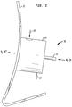
- shows a side view of a cryogen injection nozzle embodiment of the present invention, said embodiment working according to the method of the present invention;
- FIG. 2
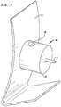
- shows a perspective view of the cryogen injection nozzle embodiment of
FIG. 1 ; - FIG. 3
- shows a more detailed perspective, exploded view of the cryogen injection nozzle embodiment of
FIG. 1 andFIG. 2 ; - FIG. 4A
- shows a top view of certain elements of the cryogen injection nozzle embodiment of
FIG. 3 ; - FIG. 4B
- shows a side cross-section view of certain elements of the cryogen injection nozzle embodiment of
FIG. 3 ; - FIG. 5
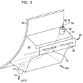
- shows a perspective, partial-transparent view of another embodiment of the injection nozzle of the present invention, said embodiment working according to the method of the present invention; and
- FIG. 6
- shows a side view partially in cross-section of the injection nozzle embodiment of
FIG. 5 . - In the appended drawing figures, like equipment is labelled with the same reference numerals throughout the description of
FIG. 1 to FIG. 6 . - Before explaining the inventive embodiments in detail, it is to be understood that the present invention is not limited in its application to the details of construction and arrangement of parts illustrated in the accompanying drawings, since the present invention is capable of other embodiments and being practiced or carried out in various ways. Also, it is to be understood that the phraseology or terminology employed herein is for the purpose of description and not of limitation.
- In order to avoid unnecessary repetitions and unless otherwise stated, the above-mentioned as well as the below-mentioned explanations regarding the features, characteristics and advantages of the respective embodiments relate
- to the
first apparatus embodiment 10 according toFIG. 1 to FIG. 4B of the present invention as well as - to the
second apparatus embodiment 100 according toFIG. 5 andFIG. 6 of the present invention. - Referring to
FIG. 1 to FIG. 3 , an injection nozzle apparatus of a first embodiment of the present invention is shown generally at 10 mounted to awall 12 of a blender or mixer (not shown) in which food product (not shown) is disposed for being chilled. While food product is referred to for being treated by theinjection nozzle 10, it is understood that other types of products can be treated with the present injection nozzle embodiment. - The
injection nozzle apparatus 10 or apparatus comprises a nozzle ornozzle portion 14, aheat sink member 16, aflow block member 18 and an outer cover orhousing 20. A mechanical fastener such as for example anut 21 removably mounts theheat sink member 16 to thenozzle portion 14 as discussed below. Thenozzle portion 14 delivers a cryogen, such as liquid nitrogen (LIN), into the blender. - The
nozzle 14 can be either a straight bore stainless steel tube or a machined steel tube with an expanding bore, wherein a diameter of the bore increases along the flow path in the direction of thewall 12. Thenozzle 14 is constructed from a material that has a low thermal mass. - Referring also to
FIG. 4A and toFIG. 4B , theheat sink member 16 is used to transfer heat to theblender wall 12 and thenozzle 14. Theheat sink member 16 is constructed with aspiral fin 17 for providing acontinuous spiral path 19 of theheat sink member 16 as shown for example inFIG. 3 and inFIG. 4A , so that any appliedheat transfer fluid 22 must travel through thespiral path 19. A higher velocity of theheat transfer fluid 22 through thespiral path 19 will provide for an increase in heat transfer between thewall 12 and theheat sink member 16. - The
heat transfer fluid 22 is discharged from theheat sink member 16 along an axial orientation of thenozzle 14 and then out of thehousing 20. Heat is first transferred into thewall 12 and then to thenozzle 14. A thermal mass of thewall 12 is greater than a thermal mass of thenozzle 14. Therefore, any of theheat transfer fluid 22 with a sufficient temperature and thermal conductivity can be used, such as for example water, steam, air, hot gas, etc. - Referring in particular to
FIG. 2 and toFIG. 3 , theflow block member 18 includes aninlet port 24 and anoutlet port 26. Thehousing 20 also includes ainlet port 28 andoutlet port 30. When theinjection nozzle 10 of for exampleFIG. 3 is assembled into what is represented atFIG. 2 , theinlet ports outlet ports heat transfer fluid 22 into thespiral path 19 for providing heat transfer and to ultimately be exhausted from theoutlet port 30. - The
flow block member 18 is used to contain and direct the flow of theheat transfer fluid 22 to theheat sink member 16 and through thespiral path 19. - The
housing 20 retains theheat sink member 16 and theflow block member 18 as being releasably mounted together and protects theinjection nozzle 10 from external pressure water sprays and cleaning agents. - The
nozzle portion 14 may be constructed from stainless steel; theheat sink member 16 may be constructed from brass, copper or any other material having high thermal conductivity; theflow block member 18 may be constructed from stainless steel or plastic; and the outer cover orhousing 20 may be constructed from stainless steel. - The
injection nozzle apparatus 10 of the embodiment shown inFIG. 1 to FIG. 4B permits thenozzle 14 to be easily cleaned, because the only element of thenozzle 14 exposed to an interior of the blender is an interior of thenozzle portion 14. Therefore, hot water or other cleaning solutions can be sprayed through thenozzle portion 14 for easy cleaning without having to disassemble theinjection nozzle 10. - Referring to
FIG. 1 ,FIG. 3 and FIG. 4A to FIG. 4B , the flow of theheat transfer fluid 22 is as follows: - The
heat transfer fluid 22 is introduced into theinlet port 28 of theouter cover 20 and flows through theinlet port 24 of theflow block 18. Theinlet ports heat transfer fluid 22. - The
heat transfer fluid 22 is thereafter introduced into thespiral path 19 of theheat sink member 16 which is seated within theflow block 18, for the fluid to move along thespiral path 19 where heat transfer occurs for thenozzle 14 and thewall 12 of the blender. Upon completion of theheat transfer fluid 22 travelling along thespiral path 19, the fluid is directed back into theflow block 18 whereupon the fluid exits the block from theoutlet port 26 as shown inFIG. 3 . - The outlet port of the
flow block member 18 may be in registration with theoutlet port 30 of theouter cover 20, when theflow block member 18 is seated within theouter cover 20 such that the fluid 22 can be exhausted quickly from theheat sink member 16 and theflow block 18. - The
heat sink member 16, theflow block member 18 and theouter cover 20 each have a corresponding centralaxial hole FIG. 3 which, when such elements are mounted to thenozzle 14, are in registration with each other so that theinjection nozzle apparatus 10 can be mounted to thewall 12 as shown inFIG. 1 to FIG. 2 . - The
nozzle portion 14 extends through thewall 12 of the blender and has an exterior threadedsurface area 15, as shown. Thenozzle portion 14 is disposed through the centralaxial hole 16a of theheat sink member 16 and the mechanical fastener, such as thenut 21, is threaded to the threadedarea 15 of thenozzle 14. Theflow block member 18 is seated by friction fit or crimping to theheat sink member 16, and theouter cover 20 may be similarly mounted to theflow block 18. - An alternate embodiment can have a
mechanical fastener 21a, for example a nut, positioned as shown to threadably engage thenozzle portion 14 where it protrudes through the centralaxial hole 20a of theouter cover 20. In such an embodiment, thenozzle portion 14 has a threaded surface area at that portion protruding from the outer cover. With this embodiment, theapparatus 10 can be fabricated as a single, integral unit to be mounted to thewall 12 of the blender. - In operation with the actual blender or mixer (not shown), a batch of food product, such as for example ground meat with ingredients therein, is placed in the blender or mixer which is started such that internal blades (not shown) of the blender or mixer mix the food product and ingredients. It is required to chill the meat during the blending operation and therefore, cryogen such as liquid nitrogen (LIN) is injected into the blender or mixer through the
injection nozzle 10. - That is, the liquid nitrogen (LIN) is injected through the
nozzle portion 14 during which heat is transferred from thewall 12 via conduction with thenozzle portion 14 which also has its temperature reduced to a temperature substantially similar to that of the liquid nitrogen (LIN). - Minimal heat is transferred between the
wall 12 and thenozzle 14 due to a low thermal mass of thenozzle portion 14. When a desired, reduced temperature of the meat is obtained, injection of the liquid nitrogen (LIN) 15 is stopped and the meat is removed from the blender or mixer. - The
heat transfer fluid 22 is introduced into theinlet port 28 of theouter cover 20 as explained above to rapidly thaw theinjection nozzle 14. Any meat or water trapped within thenozzle portion 14 is warmed and can be easily discharged at a start of the next batch of food product being used in the blender. - That is, because the
nozzle 14 has been warmed and therefore, thawed by theheat transfer fluid 22 circulating through thespiral path 19 of theheat sink member 16, the next injection of liquid nitrogen (LIN) through thenozzle portion 14 will forceably expel any trapped food product or water, or clog of such, into the blender. - The next batch of meat is thereby loaded into the blender and the process continues. The construction of the
injection nozzle apparatus 10 permits clean-in-place (CIP) of thenozzle portion 14 without removal or disassembly of the apparatus. - Referring to
FIG. 5 and toFIG. 6 , another embodiment of the injection nozzle apparatus is shown generally at 100 mounted to awall 102 of a blender or mixer (not shown). In this embodiment, water is used to defrost or thaw theapparatus 100 and thewall 102 after an injection cycle of liquid nitrogen (LIN) is introduced to the blender. - The
injection nozzle apparatus 100 includes ahousing 104 or enclosure which can be manufactured from stainless steel. Thehousing 104 includes a plurality of sidewalls, one ofsuch sidewall 106 having a surface area substantially conforming to a shape of an exterior surface of thewall 102. Thesidewall 106 permits thehousing 104 to lie flush against anexterior surface 108 of thewall 102. The sidewalls of thehousing 104 define aspace 109 or chamber therein. - An
inlet port 110 is provided at an upper sidewall of thehousing 104, while anoutlet port 112 is provided at a lower one of the sidewalls of thehousing 104. Aheat transfer fluid 114, such as for example water, is introduced into theinlet port 110 and therefore into thespace 109, with thespace 109 thus being flooded with water, after which the fluid 114 can be removed from thespace 109 through theoutlet port 112. - The sidewalls of the
housing 104 may be arranged to provide anextended portion 116 through which at least onecryogen injection nozzle 118 extends and through thespace 109 and thewall 102 for opening into the blender wherefood product 120 is being chilled. Theextended portion 116 provides a larger volume of thespace 109 only where the injection nozzle(s) 118 are disposed so that heat transfer is more thorough, uniform, and occurs more quickly. - It is not necessary to have the remainder of the
space 109 to be sized similar to that of theextended portion 116. The cryogen may be liquid nitrogen (LIN). In the embodiment shown inFIG. 5 and inFIG. 6 , there is a pair of theinjection nozzles 118, but it is understood that one or a plurality of thenozzles 118 can be used depending upon the amount of liquid nitrogen (LIN) to be introduced into the blender and the nature or type of theproduct 120 being processed therein. - During operation, the
heat transfer fluid 114, such as water for example, is purged from thespace 109 of thehousing 104, and a cryogen injection cycle begins having a duration of approximately six to eight minutes, during which occurs liquid nitrogen (LIN) injected through thenozzles 118 to thefood product 120 in the blender. - When the injection cycle stops, the
heat transfer fluid 114, in this case water, is introduced into thespace 109 from theinlet port 110 at a rate of approximately ten to thirty litres per hour for a period of from six to twelve minutes. The water will defrost or thaw the injection nozzle(s) 118 and thesurface 108 andwall 102 in close proximity to thesidewall 106. Accordingly, there should be no frozen food product or condensate in theinjection nozzle 118. - Any frozen product or moisture in the injection nozzle(s) 118 has been warmed to a temperature sufficient to eject same into the blender at the next LIN injection cycle. The
water 114 is then purged from thespace 109 of thehousing 104 and a subsequent cryogen cycle begins. - The tubing of the
injection nozzle 118 or nozzles permits clean-in-place (CIP) of thenozzle 118 without removal of same from thehousing 104. - Valving (not shown) operatively associated with the
outlet port 112 can be used to retain theheat transfer fluid 114 to a specific depth or amount in thespace 109 to carry out the heat transfer effect of thenozzles 118. - It will be understood that the embodiments described herein are merely exemplary, and that one skilled in the art may make variations and modifications without departing from the spirit and scope of the present invention. All such variations and modifications are intended to be included within the scope of the present invention as described and claimed herein. Further, all embodiments disclosed are not necessarily in the alternative, as various embodiments of the present invention may be combined to provide the desired result.
-
- 10
- apparatus, in particular injection nozzle apparatus (= first embodiment; cf.
FIG. 1 to FIG. 4B ) - 12
- wall of blender or of mixer
- 14
- nozzle or nozzle portion, in particular injection nozzle or injection nozzle portion, for example straight bore stainless steel tube or machined steel tube with expanding bore
- 15
- threaded area, in particular threaded surface area, for example exterior threaded surface area, of nozzle or
nozzle portion 14 - 16
- heat transfer housing, in particular heat sink member
- 16a
- hole, in particular central axial hole, of
heat transfer housing 16 - 17
- fin, in particular spiral fin
- 18
- block housing or block member, in particular flow block member
- 18a
- hole, in particular central axial hole, of block housing or
block member 18 - 19
- spiral path, in particular continuous spiral path, of
heat transfer housing 16 - 20
- outer cover or outer housing, in particular nozzle housing
- 20a
- hole, in particular central axial hole, of outer cover or
outer housing 20 - 21
- mechanical fastener, in particular nut, for example retaining nut
- 21a
- mechanical fastener, in particular nut, for example retaining nut
- 22
- heat transfer fluid, in particular water, steam, air, hot gas, or combination thereof
- 24
- inlet port of block housing or
block member 18 - 26
- outlet port of block housing or
block member 18 - 28
- inlet port of outer cover or
outer housing 20 - 30
- outlet port of outer cover or
outer housing 20 - 100
- apparatus, in particular injection nozzle apparatus (= second embodiment; cf.
FIG. 5 andFIG. 6 ) - 102
- wall of blender or of mixer
- 104
- enclosure or housing
- 106
- exterior surface or sidewall of enclosure or
housing 104 - 108
- external portion or exterior surface of
wall 102 - 109
- chamber or space in enclosure or
housing 104 - 110
- inlet port of enclosure or
housing 104 - 112
- outlet port of enclosure or
housing 104 - 114
- heat transfer fluid, in particular water
- 116
- extended portion of enclosure or
housing 104 - 118
- nozzle, in particular injection nozzle, for example cryogen injection nozzle
- 120
- product, in particular food product
Claims (15)
- A cryogen injection apparatus (10; 100) for injecting a cryogenic substance into a blender or mixer, comprising:- at least one nozzle (14; 118) constructed for being in fluid communication with an interior of the blender or mixer;- a heat transfer fluid (22; 114) for being operationally associated by conduction with the at least one nozzle (14; 118); and- a heat transfer housing (16) supporting the at least one nozzle (14; 118) and having a space therein for receipt of the heat transfer fluid (22; 114) to warm the at least one nozzle (14; 118).
- The apparatus (10) according to claim 1, wherein the heat transfer housing (16) comprises an enclosure having a fin (17) at the space for providing a flow path for the heat transfer fluid (22) in the space.
- The apparatus according to claim 2, wherein the flow path is continuous.
- The apparatus according to claim 2 or 3, further comprising a block housing (18) having a first open end sized and shaped to receive the heat transfer housing (16) therein to restrict the heat transfer fluid (22) to said flow path.
- The apparatus according to claim 4, further comprising an outer housing (20) having a second open end sized and shaped to receive the block housing (18) therein to protect said block housing (18) and said heat transfer housing (16).
- The apparatus (100) according to at least one of claims 1 to 5, wherein the heat transfer housing comprises an enclosure (104) having a chamber (109) therein through which the at least one nozzle (118) is disposed and in which the heat transfer fluid (114) is releasably retained to warm the at least one nozzle (118).
- The apparatus of claim 6, further comprising- an inlet port (110) in fluid communication with the chamber (109), and- an outlet port (112) in fluid communication with the chamber (109).
- The apparatus according to at least one of claims 1 to 7, wherein the heat transfer housing comprises an exterior surface (106) having a shape conforming to an external portion (108) of the blender or mixer for being mounted flush thereto.
- The apparatus according to at least one of claims 1 to 8, wherein the heat transfer fluid (22; 114) is a fluid selected from the group consisting of water, steam, air, hot gas, and combinations thereof.
- A method for heat transfer of an injection nozzle (14; 118) providing a cryogenic substance to a blender or mixer, comprising:- supporting the injection nozzle (14; 118) at a wall (12; 102) of the blender or mixer for being in communication with an interior of said blender or mixer; and- providing heat transfer with a fluid (22; 114) to said injection nozzle (14; 118).
- The method according to claim 10, wherein the warming further comprises defrosting any frozen matter within the injection nozzle (14; 118).
- The method according to claim 10 or 11, further comprising exhausting the fluid (22; 114) away from the injection nozzle (14; 118).
- The method according to at least one of claims 10 to 12, further comprising expelling any material from the injection nozzle (14; 118) for clearing said injection nozzle (14; 118).
- The method according to at least one of claims 10 to 13, further comprising retaining the fluid (22; 114) in contact with the injection nozzle (14; 118) for a select amount of time.
- The method according to at least one of claims 10 to 14, wherein the fluid (22; 114) is a substance selected from the group consisting of water, steam, air, hot gas, and combinations thereof.
Applications Claiming Priority (1)
| Application Number | Priority Date | Filing Date | Title |
|---|---|---|---|
| US201562250531P | 2015-11-04 | 2015-11-04 |
Publications (1)
| Publication Number | Publication Date |
|---|---|
| EP3165854A1 true EP3165854A1 (en) | 2017-05-10 |
Family
ID=55349733
Family Applications (1)
| Application Number | Title | Priority Date | Filing Date |
|---|---|---|---|
| EP16155127.0A Withdrawn EP3165854A1 (en) | 2015-11-04 | 2016-02-10 | Cryogen injection apparatus and corresponding method |
Country Status (3)
| Country | Link |
|---|---|
| US (1) | US20170119014A1 (en) |
| EP (1) | EP3165854A1 (en) |
| WO (1) | WO2017078944A1 (en) |
Cited By (1)
| Publication number | Priority date | Publication date | Assignee | Title |
|---|---|---|---|---|
| FR3073920A1 (en) * | 2017-11-23 | 2019-05-24 | Arianegroup Sas | PROTECTIVE METHOD AND METHOD FOR RECONDITIONING FLUID TRANSFER CONDUIT; FLUID TRANSFER DEVICE AND ERGOL FEEDER INSTALLATION FOR SPARED ENGINE |
Families Citing this family (2)
| Publication number | Priority date | Publication date | Assignee | Title |
|---|---|---|---|---|
| JP7276958B2 (en) * | 2019-07-05 | 2023-05-18 | 日本エア・リキード合同会社 | Refrigeration stirrer |
| US11635171B2 (en) * | 2020-02-10 | 2023-04-25 | Messer Industries Usa, Inc. | Fluid cryogen injector mounting apparatus and mounting method |
Citations (5)
| Publication number | Priority date | Publication date | Assignee | Title |
|---|---|---|---|---|
| GB852045A (en) * | 1956-10-13 | 1960-10-19 | Bot Brassert Oxygen Technik Ag | Improvements in or relating to blast tubes for refining crude iron |
| US3672182A (en) * | 1970-06-25 | 1972-06-27 | Air Prod & Chem | Water cooling method and apparatus employing liquid nitrogen |
| US3771718A (en) * | 1970-06-25 | 1973-11-13 | Air Prod & Chem | Water cooling method and apparatus |
| EP0844020A2 (en) * | 1996-11-22 | 1998-05-27 | Nakamichi Yamasaki | Method for spraying material particles in continous hydrothermal reaction and apparatus therefor |
| EP2700454A1 (en) * | 2012-08-22 | 2014-02-26 | Linde Aktiengesellschaft | Injection nozzle |
Family Cites Families (9)
| Publication number | Priority date | Publication date | Assignee | Title |
|---|---|---|---|---|
| US2460861A (en) * | 1945-01-18 | 1949-02-08 | Harold G Walters | Liquid sprayer |
| FR2764366B1 (en) * | 1997-06-10 | 1999-07-16 | Air Liquide | METHOD AND INSTALLATION FOR COOLING THE CONTENT OF A SPEAKER |
| JP2000280888A (en) * | 1999-03-30 | 2000-10-10 | Aisin Seiki Co Ltd | Master cylinder |
| US6510890B1 (en) * | 2000-04-14 | 2003-01-28 | Iowa State University Research Foundation, Inc. | Continuous system and method for producing frozen food products |
| US6363729B1 (en) * | 2000-07-27 | 2002-04-02 | Mg Industries | Apparatus and method for injecting cryogenic liquid into containers |
| US7043938B2 (en) * | 2002-09-05 | 2006-05-16 | Equistar Chemicals, Lp | Method of thawing a cryogenic unit |
| US6823679B2 (en) * | 2003-01-27 | 2004-11-30 | The Boeing Company | Anti-icing fluid injection nozzle |
| US20060283195A1 (en) * | 2005-06-16 | 2006-12-21 | Uwe Rosenbaum | Process and apparatus for continuous cooling of pumpable material with a liquid cryogen |
| WO2010019144A1 (en) * | 2008-08-14 | 2010-02-18 | Praxair Technology, Inc. | System and method for liquid cryogen injection in missing or blending devices |
-
2016
- 2016-02-10 EP EP16155127.0A patent/EP3165854A1/en not_active Withdrawn
- 2016-10-20 US US15/298,465 patent/US20170119014A1/en not_active Abandoned
- 2016-10-21 WO PCT/US2016/058102 patent/WO2017078944A1/en not_active Ceased
Patent Citations (5)
| Publication number | Priority date | Publication date | Assignee | Title |
|---|---|---|---|---|
| GB852045A (en) * | 1956-10-13 | 1960-10-19 | Bot Brassert Oxygen Technik Ag | Improvements in or relating to blast tubes for refining crude iron |
| US3672182A (en) * | 1970-06-25 | 1972-06-27 | Air Prod & Chem | Water cooling method and apparatus employing liquid nitrogen |
| US3771718A (en) * | 1970-06-25 | 1973-11-13 | Air Prod & Chem | Water cooling method and apparatus |
| EP0844020A2 (en) * | 1996-11-22 | 1998-05-27 | Nakamichi Yamasaki | Method for spraying material particles in continous hydrothermal reaction and apparatus therefor |
| EP2700454A1 (en) * | 2012-08-22 | 2014-02-26 | Linde Aktiengesellschaft | Injection nozzle |
Cited By (1)
| Publication number | Priority date | Publication date | Assignee | Title |
|---|---|---|---|---|
| FR3073920A1 (en) * | 2017-11-23 | 2019-05-24 | Arianegroup Sas | PROTECTIVE METHOD AND METHOD FOR RECONDITIONING FLUID TRANSFER CONDUIT; FLUID TRANSFER DEVICE AND ERGOL FEEDER INSTALLATION FOR SPARED ENGINE |
Also Published As
| Publication number | Publication date |
|---|---|
| WO2017078944A1 (en) | 2017-05-11 |
| US20170119014A1 (en) | 2017-05-04 |
Similar Documents
| Publication | Publication Date | Title |
|---|---|---|
| EP2445356B1 (en) | Semi-frozen product dispensing apparatus | |
| US20090120306A1 (en) | Systems and methods of mixing and cooling food products | |
| EP3165855A1 (en) | Cryogen injection apparatus and corresponding method | |
| CN109140833A (en) | Heat exchanger and its manufacturing method | |
| EP3159632B1 (en) | Machine for making liquid and semi-liquid products comprising a thermodynamic system | |
| US20170119014A1 (en) | Liquid nitrogen injection nozzle | |
| DE3673356D1 (en) | DEVICE FOR PRODUCING ICE CREAM, MILK SHAKE, SORBET, FROZEN SWEET FOOD AND THE LIKE EACH FROM A PUMPABLE APPROACH. | |
| AU2015333961B2 (en) | Apparatus, system and method for chilling sauces and liquids | |
| US20240268410A1 (en) | System and Method for Automatically Cleaning and Washing Ice Cream or Yogurt Machine | |
| CN104781012B (en) | Plastic Injection Nozzles for Bottom Injection Cooling | |
| US6279328B1 (en) | Cooling method and system for a rotating drum | |
| US11998025B2 (en) | System and method for automatically cleaning and washing ice cream or yogurt machine | |
| KR20170045522A (en) | Food freezing apparatus using a rotating screw with the scripper | |
| JPH07318210A (en) | Quick freezer | |
| JP2008048709A (en) | Thawing, grinding/mixing apparatus for frozen fish-paste product raw material | |
| US3214147A (en) | Freezer construction | |
| CN114041491A (en) | Fish body thawing apparatus | |
| JP2026501269A (en) | Material Cooling/Freezing Systems | |
| US3214146A (en) | Agitator and dasher assembly for ice cream freezers | |
| EP4620308A1 (en) | Method and machine for making a single-dose ice cream product | |
| JP7276958B2 (en) | Refrigeration stirrer | |
| US11690386B2 (en) | Ice cream making methods and systems | |
| WO2025215640A1 (en) | Appliance with temperature control | |
| US20100147010A1 (en) | Heat exchanger device for treating liquid food mixtures | |
| JPH0362989B2 (en) |
Legal Events
| Date | Code | Title | Description |
|---|---|---|---|
| PUAI | Public reference made under article 153(3) epc to a published international application that has entered the european phase |
Free format text: ORIGINAL CODE: 0009012 |
|
| AK | Designated contracting states |
Kind code of ref document: A1 Designated state(s): AL AT BE BG CH CY CZ DE DK EE ES FI FR GB GR HR HU IE IS IT LI LT LU LV MC MK MT NL NO PL PT RO RS SE SI SK SM TR |
|
| AX | Request for extension of the european patent |
Extension state: BA ME |
|
| STAA | Information on the status of an ep patent application or granted ep patent |
Free format text: STATUS: THE APPLICATION IS DEEMED TO BE WITHDRAWN |
|
| 18D | Application deemed to be withdrawn |
Effective date: 20171111 |