EP3165851A1 - Falling film evaporator - Google Patents
Falling film evaporator Download PDFInfo
- Publication number
- EP3165851A1 EP3165851A1 EP15815967.3A EP15815967A EP3165851A1 EP 3165851 A1 EP3165851 A1 EP 3165851A1 EP 15815967 A EP15815967 A EP 15815967A EP 3165851 A1 EP3165851 A1 EP 3165851A1
- Authority
- EP
- European Patent Office
- Prior art keywords
- tank
- refrigerant
- outlet pipe
- vapor outlet
- isolation member
- Prior art date
- Legal status (The legal status is an assumption and is not a legal conclusion. Google has not performed a legal analysis and makes no representation as to the accuracy of the status listed.)
- Withdrawn
Links
- 239000011552 falling film Substances 0.000 title claims abstract description 75
- 239000003507 refrigerant Substances 0.000 claims abstract description 288
- 239000007788 liquid Substances 0.000 claims abstract description 142
- 238000002955 isolation Methods 0.000 claims abstract description 114
- 238000005057 refrigeration Methods 0.000 claims description 5
- 239000003921 oil Substances 0.000 description 23
- 238000000926 separation method Methods 0.000 description 10
- 238000009825 accumulation Methods 0.000 description 5
- 238000001704 evaporation Methods 0.000 description 5
- 239000010721 machine oil Substances 0.000 description 5
- 230000005484 gravity Effects 0.000 description 3
- 239000012267 brine Substances 0.000 description 2
- 230000006835 compression Effects 0.000 description 2
- 238000007906 compression Methods 0.000 description 2
- 230000000694 effects Effects 0.000 description 2
- HPALAKNZSZLMCH-UHFFFAOYSA-M sodium;chloride;hydrate Chemical compound O.[Na+].[Cl-] HPALAKNZSZLMCH-UHFFFAOYSA-M 0.000 description 2
- XLYOFNOQVPJJNP-UHFFFAOYSA-N water Substances O XLYOFNOQVPJJNP-UHFFFAOYSA-N 0.000 description 2
- 230000006837 decompression Effects 0.000 description 1
- 238000012986 modification Methods 0.000 description 1
- 230000004048 modification Effects 0.000 description 1
- 239000000243 solution Substances 0.000 description 1
Images




Classifications
-
- F—MECHANICAL ENGINEERING; LIGHTING; HEATING; WEAPONS; BLASTING
- F28—HEAT EXCHANGE IN GENERAL
- F28D—HEAT-EXCHANGE APPARATUS, NOT PROVIDED FOR IN ANOTHER SUBCLASS, IN WHICH THE HEAT-EXCHANGE MEDIA DO NOT COME INTO DIRECT CONTACT
- F28D5/00—Heat-exchange apparatus having stationary conduit assemblies for one heat-exchange medium only, the media being in contact with different sides of the conduit wall, using the cooling effect of natural or forced evaporation
- F28D5/02—Heat-exchange apparatus having stationary conduit assemblies for one heat-exchange medium only, the media being in contact with different sides of the conduit wall, using the cooling effect of natural or forced evaporation in which the evaporating medium flows in a continuous film or trickles freely over the conduits
-
- F—MECHANICAL ENGINEERING; LIGHTING; HEATING; WEAPONS; BLASTING
- F25—REFRIGERATION OR COOLING; COMBINED HEATING AND REFRIGERATION SYSTEMS; HEAT PUMP SYSTEMS; MANUFACTURE OR STORAGE OF ICE; LIQUEFACTION SOLIDIFICATION OF GASES
- F25B—REFRIGERATION MACHINES, PLANTS OR SYSTEMS; COMBINED HEATING AND REFRIGERATION SYSTEMS; HEAT PUMP SYSTEMS
- F25B39/00—Evaporators; Condensers
-
- F—MECHANICAL ENGINEERING; LIGHTING; HEATING; WEAPONS; BLASTING
- F25—REFRIGERATION OR COOLING; COMBINED HEATING AND REFRIGERATION SYSTEMS; HEAT PUMP SYSTEMS; MANUFACTURE OR STORAGE OF ICE; LIQUEFACTION SOLIDIFICATION OF GASES
- F25B—REFRIGERATION MACHINES, PLANTS OR SYSTEMS; COMBINED HEATING AND REFRIGERATION SYSTEMS; HEAT PUMP SYSTEMS
- F25B39/00—Evaporators; Condensers
- F25B39/02—Evaporators
-
- F—MECHANICAL ENGINEERING; LIGHTING; HEATING; WEAPONS; BLASTING
- F25—REFRIGERATION OR COOLING; COMBINED HEATING AND REFRIGERATION SYSTEMS; HEAT PUMP SYSTEMS; MANUFACTURE OR STORAGE OF ICE; LIQUEFACTION SOLIDIFICATION OF GASES
- F25B—REFRIGERATION MACHINES, PLANTS OR SYSTEMS; COMBINED HEATING AND REFRIGERATION SYSTEMS; HEAT PUMP SYSTEMS
- F25B39/00—Evaporators; Condensers
- F25B39/02—Evaporators
- F25B39/028—Evaporators having distributing means
-
- F—MECHANICAL ENGINEERING; LIGHTING; HEATING; WEAPONS; BLASTING
- F28—HEAT EXCHANGE IN GENERAL
- F28D—HEAT-EXCHANGE APPARATUS, NOT PROVIDED FOR IN ANOTHER SUBCLASS, IN WHICH THE HEAT-EXCHANGE MEDIA DO NOT COME INTO DIRECT CONTACT
- F28D21/00—Heat-exchange apparatus not covered by any of the groups F28D1/00 - F28D20/00
- F28D21/0017—Flooded core heat exchangers
-
- F—MECHANICAL ENGINEERING; LIGHTING; HEATING; WEAPONS; BLASTING
- F28—HEAT EXCHANGE IN GENERAL
- F28D—HEAT-EXCHANGE APPARATUS, NOT PROVIDED FOR IN ANOTHER SUBCLASS, IN WHICH THE HEAT-EXCHANGE MEDIA DO NOT COME INTO DIRECT CONTACT
- F28D3/00—Heat-exchange apparatus having stationary conduit assemblies for one heat-exchange medium only, the media being in contact with different sides of the conduit wall, in which the other heat-exchange medium flows in a continuous film, or trickles freely, over the conduits
- F28D3/04—Distributing arrangements
-
- F—MECHANICAL ENGINEERING; LIGHTING; HEATING; WEAPONS; BLASTING
- F28—HEAT EXCHANGE IN GENERAL
- F28D—HEAT-EXCHANGE APPARATUS, NOT PROVIDED FOR IN ANOTHER SUBCLASS, IN WHICH THE HEAT-EXCHANGE MEDIA DO NOT COME INTO DIRECT CONTACT
- F28D7/00—Heat-exchange apparatus having stationary tubular conduit assemblies for both heat-exchange media, the media being in contact with different sides of a conduit wall
- F28D7/16—Heat-exchange apparatus having stationary tubular conduit assemblies for both heat-exchange media, the media being in contact with different sides of a conduit wall the conduits being arranged in parallel spaced relation
-
- F—MECHANICAL ENGINEERING; LIGHTING; HEATING; WEAPONS; BLASTING
- F28—HEAT EXCHANGE IN GENERAL
- F28F—DETAILS OF HEAT-EXCHANGE AND HEAT-TRANSFER APPARATUS, OF GENERAL APPLICATION
- F28F9/00—Casings; Header boxes; Auxiliary supports for elements; Auxiliary members within casings
- F28F9/22—Arrangements for directing heat-exchange media into successive compartments, e.g. arrangements of guide plates
-
- F—MECHANICAL ENGINEERING; LIGHTING; HEATING; WEAPONS; BLASTING
- F25—REFRIGERATION OR COOLING; COMBINED HEATING AND REFRIGERATION SYSTEMS; HEAT PUMP SYSTEMS; MANUFACTURE OR STORAGE OF ICE; LIQUEFACTION SOLIDIFICATION OF GASES
- F25B—REFRIGERATION MACHINES, PLANTS OR SYSTEMS; COMBINED HEATING AND REFRIGERATION SYSTEMS; HEAT PUMP SYSTEMS
- F25B2339/00—Details of evaporators; Details of condensers
- F25B2339/02—Details of evaporators
- F25B2339/024—Evaporators with refrigerant in a vessel in which is situated a heat exchanger
- F25B2339/0242—Evaporators with refrigerant in a vessel in which is situated a heat exchanger having tubular elements
Definitions
- the present invention relates to a falling film evaporator.
- patent literature 1 JP-A No. H 8-189726 discloses a falling film evaporator.
- the falling film evaporator is a heat exchanger in which a liquid refrigerant distribution apparatus is provided between a heat transfer tube group in a tank and a vapor outlet pipe extending out from the upper portion of the tank; the liquid refrigerant distribution apparatus allows liquid refrigerant to fall downwardly onto the heat transfer tube group; the heat transfer tube group allows the fallen liquid refrigerant to evaporate.
- Gas refrigerant evaporated by the heat transfer tube group flows out of the tank through the vapor outlet pipe extending out from the upper portion of the tank and is sent to a compressor.
- the refrigerant in a gas-liquid two-phase state flows into the liquid refrigerant distribution apparatus through a refrigerant inlet pipe provided on the tank.
- the gas refrigerant in the refrigerant in a gas-liquid two-phase state which has flowed into the liquid refrigerant distribution apparatus and the gas refrigerant generated as a result of evaporating with the heat transfer tube group flow toward the vapor outlet pipe provided in the upper portion of the tank.
- the liquid refrigerant downwardly falling from the liquid refrigerant distribution apparatus is less prone to flowing out through the vapor outlet pipe because the liquid refrigerant is distant from the vapor outlet pipe.
- the vapor outlet pipe extends out from a location other than the upper middle portion of the tank, for example, in the case in which a different member needs to be disposed on the upper portion of the tank, in the case in which an end of the vapor outlet pipe is not connected to the upper portion of the tank, or the like, the following portions of the liquid refrigerant downwardly falling from the liquid refrigerant distribution apparatus are generated: some portion is prone to reaching the vapor outlet pipe, and other portion is less prone to reaching the vapor outlet pipe.
- the gas refrigerant flowing through this portion may carry the liquid refrigerant to cause the carryover in which the liquid refrigerant flows out of the tank through the vapor outlet pipe.
- the present invention has been created in view of the above. It is an object of the present invention to provide a falling film evaporator which is able to reduce an outflow of liquid refrigerant even in the case in which the vapor outlet pipe is provided in a location other than the upper middle portion of the tank.
- a falling film evaporator is a falling film evaporator used for a refrigeration apparatus.
- the falling film evaporator includes a heat transfer tube group, a tank, a liquid refrigerant distribution part, a vapor outlet pipe, and an isolation member.
- the heat transfer tube group has a plurality of heat transfer tubes flowing heat medium therein and longitudinally extending.
- the tank has the heat transfer tube group disposed therein and is provided with a refrigerant flow inlet.
- the liquid refrigerant distribution part allows liquid refrigerant of refrigerant in a gas-liquid two-phase state supplied in the tank through the refrigerant flow inlet to downwardly fall onto the heat transfer tube group.
- the vapor outlet pipe extends out from a lateral or upper position of the tank other than a top of the tank as viewed in the longitudinal direction of the tank.
- the isolation member covers a place below a lowest portion of a connection portion of the tank and the vapor outlet pipe as viewed in the axial direction of the heat transfer tubes, extends between the vapor outlet pipe and the liquid refrigerant distribution part, and allows refrigerant to pass through an upper portion.
- the isolation member is provided such that the longitudinal direction of the isolation member is same as the longitudinal direction of the heat transfer tubes.
- the position in which the vapor outlet pipe extends out from the tank is a lateral or upper position of the tank other than a top of the tank as viewed in the longitudinal direction of the tank; for example, the vapor outlet pipe may be provided such that the vapor outlet pipe extends out from a position higher than the liquid refrigerant distribution part.
- the lateral or upper position (excluding the top) in which the vapor outlet pipe extends out as viewed in the longitudinal direction of the tank can be in a range of ⁇ 10 through ⁇ 100 degrees from the vertically top relative to the center of gravity of the tank as viewed in the longitudinal direction of the tank.
- the longitudinal direction of the isolation member does not need to be exactly same as the longitudinal direction of the heat transfer tubes; for example, the longitudinal direction of the heat transfer tubes may be different from the longitudinal direction of the isolation member in a range of ⁇ 10 degrees to be substantially same as the longitudinal direction of the isolation member.
- liquid refrigerant may be present close to the vapor outlet pipe.
- the isolation member is provided to prevent liquid refrigerant close to the vapor outlet pipe from directly flowing toward the vapor outlet pipe. More specifically, even if the liquid refrigerant attempts to flow beyond the isolation member through the upper portion of the isolation member, the liquid refrigerant is less prone to flowing upwardly and less prone to reaching the vapor outlet pipe due to the own weight of the liquid refrigerant.
- the liquid refrigerant is less prone to reaching the vapor outlet pipe because the isolation member is provided such that the longitudinal direction of the isolation member is same as the longitudinal direction of the heat transfer tubes, so that the isolation member is configured to lengthen a movement distance through which the liquid refrigerant needs to flow around a longitudinal end portion of the isolation member to reach the vapor outlet pipe.
- a falling film evaporator according to a second aspect is the falling film evaporator according to the first aspect, in which the isolation member extends to an inner surface of the tank above the vapor outlet pipe as viewed in the axial direction of the heat transfer tubes and has an upper opening through an upper portion of the isolation member in the thickness direction thereof, or the isolation member extends, beyond an upper side of the vapor outlet pipe as viewed in the direction in which the vapor outlet pipe extends out from the tank, short of a portion of the inner surface of the tank above the vapor outlet pipe to form an upper gap.
- the number of the upper gaps is not limited to one, and projections and depressions may be formed in the upper end portion of the isolation member to form a plurality of upper gaps between the isolation member and the inner surface of the tank.
- a falling film evaporator according to the third aspect is the falling film evaporator according to the second aspect, in which the upper openings or the upper gaps are separately provided such that the upper openings or the upper gaps closer to the vapor outlet pipe have larger passage resistances to refrigerant passing through the upper openings or the upper gaps.
- a falling film evaporator according to the fourth aspect is the falling film evaporator according to the second or third aspect, in which the upper opening or the upper gap is provided in a position vertically higher than the connection portion of the vapor outlet pipe and the tank.
- a falling film evaporator according to the fifth aspect is the falling film evaporator according to any one of the second through fourth aspects, in which an oil return opening is formed in the lower end of the isolation member, or an oil return gap is formed between the lower end of the isolation member and the inner surface of the tank.
- the oil return opening and the oil return gap are smaller than the upper opening and the upper gap.
- a falling film evaporator according to the sixth aspect is the falling film evaporator according to any one of the first through fifth aspects, in which a longitudinal end portion of the isolation member is connected to an inner wall of the tank.
- the liquid refrigerant can be more effectively prevented from reaching the vapor outlet pipe via the longitudinal end portion of the isolation member.
- an outflow of the liquid refrigerant from the vapor outlet pipe is able to be prevented.
- the flow velocity of the refrigerant in the vicinity of the vapor outlet pipe is able to be effectively reduced.
- the liquid refrigerant is readily prevented from reaching the vapor outlet pipe against its own weight.
- the liquid refrigerant can be more effectively prevented from reaching the vapor outlet pipe via the longitudinal end portion of the isolation member.
- FIG. 1 is an external view of a falling film evaporator 1 according to an embodiment of the present invention.
- the falling film evaporator 1 is used as an evaporator of a relatively large capacity refrigeration apparatus such as a centrifugal chiller. More specifically, such a refrigeration apparatus is provided with the falling film evaporator 1 as well as a compressor, a radiator, an expansion mechanism and the like (not illustrated).
- a vapor compression refrigerant circuit is configured with these devices. Then, in such a vapor compression refrigerant circuit, gas refrigerant discharged from the compressor radiates heat in the radiator. This refrigerant, which has radiated heat in the radiator, is decompressed in the expansion mechanism to be refrigerant in a gas-liquid two-phase state.
- This refrigerant in a gas-liquid two-phase state flows into the falling film evaporator 1, exchanges heat with heat medium such as water and brine to evaporate into gas refrigerant, and flows out of the falling film evaporator 1.
- This gas refrigerant which has flowed out of the falling film evaporator 1, again is sucked into the compressor.
- the liquid refrigerant which has not been evaporated as a result of the exchange of heat with the heat medium such as water and brine, merges with refrigerant in a gas-liquid two-phase state flowing into the falling film evaporator 1 through a liquid refrigerant return tube or the like (not illustrated), and again flows into the falling film evaporator 1.
- FIGS. 1 through 4 a transversely placed shell and tube type heat exchanger is employed as the falling film evaporator 1.
- the falling film evaporator 1 primarily has a tank 10, a heat transfer tube group 20, a liquid refrigerant distribution apparatus 30, and an isolation member 50.
- FIG. 2 is a perspective view illustrating an internal structure of the falling film evaporator 1.
- FIG. 3 is a cross sectional view of the falling film evaporator 1 as viewed in the horizontal direction orthogonal to the longitudinal direction of the tank 10 (here, the isolation member 50 is not illustrated).
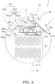
- FIG. 4 is a cross sectional view of a portion of the falling film evaporator 1 in which the vapor outlet pipe 18 is located as viewed in the longitudinal direction of the tank 10.
- the tank 10 primarily has a shell 11 and heads 12a, 12b.
- the shell 11 is a transversely placed cylindrical member having openings in both longitudinal end portions.
- the heads 12a, 12b are bowl-shaped members closing the openings in both of the longitudinal end portions of the shell 11.
- a head of the heads 12a, 12b disposed on the left side of the shell 11 is referred to as a head 12a
- a head of the heads 12a, 12b disposed on the right side of the shell 11 is referred to as a head 12b.
- a tube plate 13a is interposed between the head 12a and the shell 11.
- a tube plate 13b is interposed between the head 12b and the shell 11.
- the tube plates 13a, 13b are substantially disc-shaped members.
- tube holes are formed to fix a plurality of heat transfer tubes 21 constituting the heat transfer tube group 20 in a state in which both longitudinal end portions of the heat transfer tubes 21 have been inserted therethrough.
- a space in the tank 10 is horizontally divided into a head space SH1 surrounded by the head 12a and the tube plate 13a, a shell space SS surrounded by the shell 11 and the tube plates 13a, 13b, and a head space SH2 surrounded by the head 12b and the tube plate 13b.
- the head 12a is provided with a heat medium inlet pipe 14 and a heat medium outlet pipe 15.
- the heat medium inlet pipe 14 is a pipe member for allowing the heat medium to flow into the head space SH1 in the tank 10.
- the heat medium inlet pipe 14 is provided in the lower portion of the head 12a.
- the heat medium outlet pipe 15 is a pipe member for allowing the heat medium to flow out of the head 12a of the tank 10.
- the heat medium outlet pipe 15 is provided in the upper portion of the head 12a.
- the head space SH1 is vertically divided by a head space separate plate 16 into a lower head space SHi communicating with the heat medium inlet pipe 14 and an upper head space SHo communicating with the heat medium outlet pipe 15.
- the heat medium which has flowed into the lower head space SHi in the head 12a through the heat medium inlet pipe 14, flows into a plurality of heat transfer tubes 21 (here, heat transfer tubes 21 constituting the lower portion of the heat transfer tube group 20) communicating with the lower head space SHi, and is sent to the head space SH2.
- the heat medium sent to this head space SH2 has flowed and turned upwardly in the head space SH2
- the heat medium flows into a plurality of heat transfer tubes (here, heat transfer tubes 21 constituting the upper portion of the heat transfer tube group 20) communicating with the upper head space SHo, and is sent to the upper head space SHo.
- the heat medium sent to this upper head space SHo flows out of the upper head space SHo through the heat medium outlet pipe 15 (i.e., the heat medium flows out of the falling film evaporator 1).
- the shell 11 is provided with a refrigerant inlet pipe 17, a vapor outlet pipe 18, and a liquid outlet pipe 19.
- the refrigerant inlet pipe 17 is a pipe member for allowing the refrigerant in a gas-liquid two-phase state to flow into the shell space SS in the tank 10.
- the refrigerant inlet pipe 17 is provided in the upper portion of the shell 11 to the left of the shell 11 in the longitudinal direction thereof.
- the refrigerant inlet pipe 17 has a refrigerant flow inlet in the end thereof in the shell 11 allowing the refrigerant to flow into the tank 10.
- the vapor outlet pipe 18 is a pipe member for allowing the gas refrigerant generated as a result of evaporating on the heat transfer tube group 20 to flow out of the shell space SS in the tank 10.
- this vapor outlet pipe 18 is provided in an upper portion of the shell 11 which is inclined at approximately 30 degrees from the upper direction at the top of the shell 11 as viewed in the longitudinal direction of the shell 11.
- the vapor outlet pipe 18 is also provided to extend out from a substantially longitudinal middle portion of the shell 11. It should be noted that an axial inclination angle of the vapor outlet pipe 18 at a connection portion of the vapor outlet pipe 18 and the shell 11 may be in a range of ⁇ 10 through ⁇ 100 degrees or ⁇ 30 through ⁇ 60 degrees.
- connection position of the vapor outlet pipe 18 and the shell 11 is located above a second stage refrigerant tray 35 of the liquid refrigerant distribution apparatus 30.
- the liquid outlet pipe 19 is a pipe member for flowing the liquid refrigerant which has not evaporated on the heat transfer tube group 20 out of the shell space SS in the tank 10.
- the liquid outlet pipe 19 is provided in the lower portion of the shell 11 at the substantially longitudinal middle of the shell 11.
- the liquid refrigerant distributed on the heat transfer tube group 20 exchanges heat with the heat medium flowing inside of the heat transfer tubes 21 constituting the heat transfer tube group 20 to evaporate into gas refrigerant.
- the gas refrigerant generated as a result of evaporating on the heat transfer tube group 20 flows diagonally upwardly toward the vapor outlet pipe 18, and flows out of the shell space SS in the tank 10 through the vapor outlet pipe 18.
- the gas refrigerant which has flowed out of this shell space SS in the tank 10 is again sucked into the compressor.
- the liquid refrigerant which has not evaporated on the heat transfer tube group 20 flows out of the shell space SS in the tank 10 through the liquid outlet pipe 19 provided below the shell space SS in the tank 10.
- This liquid refrigerant which has flowed out of the shell space SS in the tank 10 merges with the refrigerant in a gas-liquid two-phase state flowing into the shell space SS in the tank 10 through the liquid refrigerant return tube and the like. Then this liquid refrigerant again flows into the shell space SS in the tank 10 through the refrigerant inlet pipe 17.
- the heat transfer tube group 20 has the plurality of heat transfer tubes 21 extending in the longitudinal direction of the tank 10.
- the heat transfer tube group 20 is disposed in a portion substantially horizontally middle and vertically lower in the shell space SS in the tank 10 as viewed in the longitudinal direction of the tank 10.
- the heat transfer tubes 21 are disposed in multiple stages and multiple columns as viewed in the longitudinal direction of the tank 10, here, in a staggered pattern of 11 columns ⁇ 9 stages. Both of the longitudinal end portions of heat transfer tubes 21 extend to the tube plates 13a, 13b, and are fixed in the state in which the end portions have been inserted through the tube holes (not illustrated) of the tube plates 13a, 13b.
- both of the longitudinal end portions of heat transfer tubes 21 constituting a vertically upper portion of the heat transfer tube group 20 communicate with the lower portion of the head space SH2 and the lower head space SHi.
- Both of the longitudinal end portions of the heat transfer tubes 21 constituting a vertically lower portion of the heat transfer tube group 20 communicate with the upper portion of the head space SH2 and the upper head space SHo.
- the number and the arrangement of the heat transfer tubes 21 constituting the heat transfer tube group 20 are not limited to the number and the arrangement in the present embodiment, and the number and/or the arrangement of the heat transfer tubes 21 different from those in the present embodiment may be employed. Moreover, in the case in which a tank having a tube plate and a head in only one longitudinal end portion of the shell is employed, a U-shaped heat transfer tube may be employed.
- the liquid refrigerant distribution apparatus 30 is disposed vertically between the heat transfer tube group 20 in the shell space SS in the tank 10 and the vapor outlet pipe 18.
- the liquid refrigerant distribution apparatus 30 primarily has a header pipe 31, a refrigerant tray 33, and an upper cover 36.
- the header pipe 31 is a pipe member for introducing the refrigerant in a gas-liquid two-phase state supplied into the shell space SS in the tank 10 through the refrigerant inlet pipe 17 into the refrigerant tray 33 (here, a first stage refrigerant tray 34).
- the header pipe 31 is a pipe member extending in the longitudinal direction of the tank 10. One end portion of the header pipe 31 (here, the left end portion) is connected to the refrigerant inlet pipe 17.
- the header pipe 31 has a substantially cross-sectional shape as viewed in the longitudinal direction of the tank 10.
- header pipe refrigerant holes 31c allow the refrigerant in a gas-liquid two-phase state flowing through the header pipe 31 to flow out toward the first stage refrigerant tray 34.
- a gas-liquid separation member 32 is provided on the header pipe 31, excluding the one end portion (here, the left end portion of the header pipe 31) connected to the refrigerant inlet pipe 17, a gas-liquid separation member 32 is provided.
- the gas-liquid separation member 32 covers the upper wall 31a and the outer peripheries of the upper portions of the side walls 31 b of the header pipe 31 in a state in which the gas-liquid separation member 32 is spaced from the outer periphery of the header pipe 31.
- the gas-liquid separation member 32 has a substantially downward U-shaped cross-sectional shape as viewed in the longitudinal direction of the tank 10. Then, in the gas-liquid separation member 32, many header pipe vent holes 32a are formed.
- the header pipe vent holes 32a are holes for permitting the gas refrigerant of the refrigerant in a gas-liquid two-phase state flowing inside the header pipe 31, which has been supplied in the shell space SS in the tank 10 through the refrigerant inlet pipe 17, to pass and for preventing the liquid refrigerant of the refrigerant in a gas-liquid two-phase state flowing inside the header pipe 31, which has been supplied in the shell space SS in the tank 10 through the refrigerant inlet pipe 17, from passing.
- the refrigerant tray 33 is a tray-shaped member for allowing the liquid refrigerant of the refrigerant in a gas-liquid two-phase state, which has been supplied in the shell space SS in the tank 10 through the refrigerant inlet pipe 17 provided on and in the shell 11 of the tank 10, to downwardly fall onto the lower heat transfer tube group 20 after accumulating the liquid refrigerant.
- the refrigerant tray 33 primarily has the first stage refrigerant tray 34 and the second stage refrigerant tray 35.
- the first stage refrigerant tray 34 is a tray-shaped member allowing the liquid refrigerant of the refrigerant in a gas-liquid two-phase state, which has been supplied in the shell space SS in the tank 10 through the refrigerant inlet pipe 17 provided on and in the shell 11 of the tank 10, to downwardly fall after accumulating the liquid refrigerant.
- the first stage refrigerant tray 34 extends in the longitudinal direction of the tank 10.
- the first stage refrigerant tray 34 has a substantially upward U-shaped cross-sectional shape as viewed in the longitudinal direction of the tank 10.
- the header pipe 31 is disposed on a bottom wall 34a of the first stage refrigerant tray 34.
- the refrigerant in a gas-liquid two-phase state which has been supplied in the shell space SS in the tank 10 through the refrigerant inlet pipe 17, is introduced into the first stage refrigerant tray 34 through the header pipe refrigerant holes 31c of the header pipe 31 and the header pipe vent holes 32a of the gas-liquid separation member 32.
- the refrigerant in a gas-liquid two-phase state introduced in the first stage refrigerant tray 34 from the header pipe 31 is separated into gas and liquid by the gas-liquid separation member 32.
- liquid refrigerant of the refrigerant in a gas-liquid two-phase state does not pass through the header pipe vent holes 32a of the gas-liquid separation member 32, is introduced into the first stage refrigerant tray 34, and is accumulated in the first stage refrigerant tray 34.
- the liquid refrigerant accumulated in the first stage refrigerant tray 34 downwardly falls onto the lower second stage refrigerant tray 35 through a plurality of liquid refrigerant downwardly falling holes 34c formed in the bottom wall 34a of the first stage refrigerant tray 34.
- the gas refrigerant of the refrigerant in a gas-liquid two-phase state passes through the header pipe vent holes 32a of the gas-liquid separation member 32, and is introduced into a directly above-first stage refrigerant tray space SSd1 directly above the first stage refrigerant tray 34 (here, a space vertically between the upper cover 36 and the first stage refrigerant tray 34).
- the gas refrigerant introduced in the directly above-first stage refrigerant tray space SSd1 flows toward the vapor outlet pipe 18, flows out of the shell space SS in the tank 10 through the vapor outlet pipe 18 together with the gas refrigerant generated as a result of evaporating on the heat transfer tube group 20.
- the second stage refrigerant tray 35 is a tray-shaped member allowing the liquid refrigerant downwardly falling from the first stage refrigerant tray 34 to downwardly fall onto the lower heat transfer tube group 20 after accumulating the liquid refrigerant.
- the second stage refrigerant tray 35 extends in the longitudinal direction of the tank 10.
- the second stage refrigerant tray 35 is provided such that the longitudinal direction of the second stage refrigerant tray 35 is the same as the longitudinal direction of the heat transfer tubes 21.
- the second stage refrigerant tray 35 has a substantially upward U-shaped cross-sectional shape as viewed in the longitudinal direction of the tank 10.
- the second stage refrigerant tray 35 extends off the first stage refrigerant tray 34 as the second stage refrigerant tray 35 is viewed from below (likely, as the second stage refrigerant tray 35 is viewed in the longitudinal direction of the tank 10). That is, as the second stage refrigerant tray 35 is viewed in the longitudinal direction of the tank 10, side walls 35b of the second stage refrigerant tray 35 are disposed outside side walls 34b of the first stage refrigerant tray 34. Thereby, the liquid refrigerant downwardly falling from the first stage refrigerant tray 34 is introduced into the second stage refrigerant tray 35, and is accumulated in the second stage refrigerant tray 35.
- the liquid refrigerant accumulated in the second stage refrigerant tray 35 downwardly falls onto the lower heat transfer tube group 20 through a plurality of liquid refrigerant downwardly falling holes 35c formed in a bottom wall 35a of the second stage refrigerant tray 35.
- a space vertically between the first stage refrigerant tray 34 and the second stage refrigerant tray 35 is referred to as a directly above-second stage refrigerant tray space SSd2.
- the upper cover 36 is a roof-shaped member spaced above the refrigerant tray 33 (here, the first stage refrigerant tray 34) and covering the refrigerant tray 33 (here, the first stage refrigerant tray 34) thereabove and diagonally thereabove.
- the upper cover 36 extends in the longitudinal direction of the tank 10 excluding the end portion (here, the left end portion of the header pipe 31) in which the refrigerant inlet pipe 17 is connected to the header pipe 31.
- the upper cover 36 has a substantially downward U-shaped cross-sectional shape as viewed in the longitudinal direction of the tank 10.
- the upper cover 36 has an upper wall 36a having a horizontal plate-shaped cross-sectional shape as viewed in the longitudinal direction of the tank 10, side walls 36b extending diagonally downwardly from the end portion of the upper wall 36a, and wall end portions 36c extending downwardly from the lower ends of the side walls 36b.
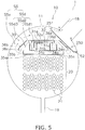
- the side walls 36b and the wall end portions 36c of the upper cover 36a extend diagonally downwardly toward locations lower than the lower edge of the connection portion of the vapor outlet pipe 18 and the shell 11 (a portion indicated by the point X in FIG. 5 ).
- the upper wall 36a of the upper cover 36 is located further above the header pipe 31 located above the second stage refrigerant tray 35.
- the upper cover 36 is viewed in the longitudinal direction of the tank 10, the upper cover 36 is provided with projection walls 36d downwardly projecting in positions outside the header pipe 31 and the gas-liquid separation member 32 as well as inner side of the side walls 34b of the first stage refrigerant tray 34.
- the projection walls 36d extend in the longitudinal direction of the tank 10. Then, the upper cover 36 covers and extends off the first stage refrigerant tray 34 as the upper cover 36 is viewed from above (likewise, in the case in which as the upper cover 36 is viewed in the longitudinal direction of the tank 10).
- the distribution apparatus space SSd is a space vertically between the upper cover 36 and the refrigerant tray 33 (here, the second stage refrigerant tray 35).
- the distribution apparatus space SSd has the directly above-first stage refrigerant tray space SSd1 as described above, the directly above-second stage refrigerant tray space SSd2 as described above, and first stage refrigerant tray lateral spaces SSd3.
- the first stage refrigerant tray lateral spaces SSd3 are a space above the second stage refrigerant tray 35 and outside the side walls 34b of the first stage refrigerant tray 34 as the liquid refrigerant distribution apparatus 30 is viewed in the longitudinal direction of the tank 10.
- spaces in the shell space SS in the tank 10 excluding the distribution apparatus space SSd constitute a vapor main flow path space SSv through which the gas refrigerant generated as a result of evaporating on the heat transfer tube group 20 flows toward the vapor outlet pipe 18.
- the vapor main flow path space SSv communicates with the first stage refrigerant tray lateral spaces SSd3 of the distribution apparatus space SSd through gaps vertically between the end portions of the side walls 36b of the upper cover 36 and upper ends of the side walls 35b of the second stage refrigerant tray 35 as the liquid refrigerant distribution apparatus 30 is viewed in the longitudinal direction of the tank 10.
- the configuration having the first stage refrigerant tray 34 and the second stage refrigerant tray 35 is employed as a basic configuration of the liquid refrigerant distribution apparatus 30, the configuration having the first stage refrigerant tray 34 and the second stage refrigerant tray 35 is employed. Then, such a liquid refrigerant distribution apparatus 30 and the heat transfer tube group 20 having the heat transfer tubes 21 constitute the falling film evaporator 1 allowing the liquid refrigerant to evaporate as a result of exchanging heat between the heat medium flowing inside the heat transfer tubes 21 and the liquid refrigerant downwardly falling from the second stage refrigerant tray 35.
- the isolation member 50 is provided in the tank 10 and in the vicinity of the portion connected to the vapor outlet pipe 18.
- This isolation member 50 is provided so as to cover a place below the lowest portion (the point X in FIG. 4 ) of the connection portion of the tank 10 and the vapor outlet pipe 18 as viewed in the axial direction of the heat transfer tubes 21, to extend between the vapor outlet pipe 18 and the liquid refrigerant distribution apparatus 30, and to allow the refrigerant to pass through the upper portion thereof. As illustrated in FIG. 2 , this isolation member 50 extends in the longitudinal direction of the heat transfer tubes 21, so that the longitudinal direction of the isolation member 50 is substantially same as the longitudinal direction of the heat transfer tubes 21.
- both of longitudinal ends of the isolation member 50 extend short of the tube plates 13a, 13b, so that the both ends are not welded or the like to the tube plates 13a, 13b or an inner wall of the tank 10, and are open toward the longitudinal direction of the heat transfer tubes 21.
- the isolation member 50 extends, from a position below the lowest portion (the point X) of the connection portion of the tank 10 and the vapor outlet pipe 18, beyond the upper side of the vapor outlet pipe 18 as viewed in the direction in which the vapor outlet pipe 18 extends out from the tank 10, but the isolation member 50 does not extend to reach an inner surface of the tank 10. It should be noted that, the isolation member 50 extends above the highest portion (the point Y in FIG. 4 ) of the connection portion of the tank 10 and the vapor outlet pipe 18 in the case in which the falling film evaporator 1 is horizontally viewed.
- An upper gap 51 is formed between the upper end of the isolation member 50 and the inner surface of the tank 10 nearest the upper end of the isolation member 50. It should be noted that, in the present embodiment, the upper end of the isolation member 50 is rectilinearly formed along the longitudinal direction of the heat transfer tubes 21.
- This upper gap 51 is provided above the highest portion (the point Y in FIG. 4 ) of the connection portion of the tank 10 and the vapor outlet pipe 18 to be disposed in a position higher than the connection portion of the tank 10 and the vapor outlet pipe 18 in the case in which the falling film evaporator 1 is horizontally viewed.
- the isolation member 50 is welded to a portion of the inner wall of the tank 10 lower than the lowest portion (the point X) of the connection portion of the tank 10 and the vapor outlet pipe 18 to be fixed thereto.
- the isolation member 50 extends from this fixation portion, that is, the portion lower than the lowest portion (the point X) of the connection portion of the tank 10 and the vapor outlet pipe 18, slightly far toward the vicinity of the middle of the tank 10, and horizontally toward the inside of the tank 10 as well as vertically toward the upper portion of the tank 10. Then, a portion extending vertically upwardly is provided in the vicinity of the upper end of the isolation member 50.
- an oil return opening 52 which is a fine opening vertically therethrough is provided.
- This oil return opening 52 has a maximum passage area configured to be smaller than the maximum passage area of the above described upper gap 51.
- the isolation member 50 is disposed to adjust the size of the passage area in the narrow gap between the upper cover 36 and the isolation member 50 such that the flow velocity of the refrigerant flowing through the portion distant from the vapor outlet pipe 18 is approximately same as the flow velocity of the refrigerant flowing through the portion close to the vapor outlet pipe 18.
- the gas refrigerant having a fast flow velocity may carry the liquid refrigerant to readily cause the carryover in which the liquid refrigerant flows out of the tank.
- the connection position of the vapor outlet pipe 18 and the tank 10 is provided in a portion close to a position through which the liquid refrigerant passes, the carryover more readily occurs.
- the vapor outlet pipe 18 is connected not to the top of the tank 10 but to an inclined position, so that the vapor outlet pipe 18 is connected to a portion close to a position through which the liquid refrigerant from the header pipe 31 and/or the liquid refrigerant distribution apparatus 30 passes. Even in such a connection state, the isolation member 50 is provided between the vapor outlet pipe 18 and the liquid refrigerant distribution apparatus 30.
- the refrigerant which have flowed out of the header pipe 31 flows around the upper cover 36 and further toward the vapor outlet pipe 18 side, and through the portion close to the vapor outlet pipe 18, the refrigerant flows around the upper cover 36, then further passes the narrow gap between the upper cover 36 and the isolation member 50, and flows toward the vapor outlet pipe 18 side (here, because the open portions in both of the longitudinal end portions of the isolation member 50 are located away from the vapor outlet pipe 18, the refrigerant hardly flows through the open portions).
- the liquid refrigerant is less prone to passing through the upper gap 51 because channels to the vapor outlet pipe 18 are sufficiently long, and the upper gap 51 through which the refrigerant passes is provided upward in the tank 10, so that the liquid refrigerant having a specific gravity greater than the gas refrigerant needs to upwardly rises and flows against its own weight.
- the isolation member 50 can reduce an outflow of the liquid refrigerant.
- the isolation member 50 is disposed to adjust the size of the passage area in the narrow gap between the upper cover 36 and the isolation member 50 such that the flow velocity of the refrigerant flowing through the portion distant from the vapor outlet pipe 18 is approximately same as the flow velocity of the refrigerant flowing through the portion close to the vapor outlet pipe 18, the difference between the flow velocities of the refrigerant in the portion distant from the vapor outlet pipe 18 and the portion close to the vapor outlet pipe 18 can be reduced.
- the isolation member 50 is provided, thereby enabling the refrigerant of the refrigerant passing through the header pipe 31 and the liquid refrigerant distribution apparatus 30 on the side close to the vapor outlet pipe 18 to flow long away around the isolation member 50. Accordingly, it becomes possible to balance the distribution of the refrigerant flowing through the portion close to the vapor outlet pipe 18 and the refrigerant flowing through the portion distant from the vapor outlet pipe 18.
- the upper gap 51 which is formed between the upper end of the isolation member 50 and the inner wall of the tank 10, is provided above the highest portion (the point Y in FIG. 4 ) of the connection portion of the tank 10 and the vapor outlet pipe 18 in the case in which the falling film evaporator 1 is horizontally viewed. Therefore, the liquid refrigerant having a specific gravity greater than the gas refrigerant is able to be less prone to reaching the upper gap 51.
- the oil return opening 52 is formed in the vicinity of the lower end of the isolation member 50, the accumulation of refrigerating machine oil between the isolation member 50 and the inner wall of the tank 10 is able to be prevented.
- the oil return opening 52 prevents the accumulation of the refrigerating machine oil
- the oil return opening 52 having a size configured to be sufficiently smaller than the upper gap 51 prevents the liquid refrigerant from passing through the oil return opening 52 and reaching the vapor outlet pipe 18.
- the isolation member 50 is formed so as to extend such that the longitudinal direction of the isolation member 50 is same as the longitudinal direction of the heat transfer tubes 21.
- the upper gap 51 formed between the upper end of the isolation member 50 and the inner surface of the tank 10 is described as an example.
- an isolation member 250 may extend to reach the inner wall of the tank 10 and have an upper opening 251 through in the thickness direction of isolation member 250 formed at an upper portion slightly below the upper end of the isolation member 250.
- both of the longitudinal ends of the isolation member 50 which are not welded or the like and are open, are described as an example.
- both longitudinal ends 350P, 350Q of an isolation member 350 may extend to reach the tube plates 13a, 13b and be welded and the like to be connected to the tube plates 13a, 13b.
- both of the longitudinal ends 350P, 350Q may be bent and the like toward the inner wall of the tank 10 side, and be welded and the like to be connected to the inner wall of the tank 10.
- the longitudinal end portions of the isolation member may be configured to be closed.
- the liquid refrigerant can more effectively be prevented from more flowing toward the vapor outlet pipe 18 via the longitudinal end portions of the isolation member (passing outside the longitudinal end portions of the isolation member) and reaching the vapor outlet pipe 18.
- the heat transfer tube group 20 which is housed in the tank 10, disposed such that the longitudinal direction of the heat transfer tube group 20 is same as the longitudinal direction of the tank 10 is described as an example.
- the heat transfer tube group 20 housed in the tank 10 may be disposed such that the longitudinal direction of the heat transfer tube group 20 is different from the longitudinal direction of the tank 10 to some extent; for example, the heat transfer tube group 20 may be disposed in the tank 10 such that the angle between the longitudinal direction of the heat transfer tube group 20 and the longitudinal direction of the tank 10 falls within ⁇ 20 degrees.
- the oil return opening 52 vertically through the isolation member 50 provided in the vicinity of the lower end of the isolation member 50 is described as an example.
- an oil return gap may be formed between the lower end portion of the isolation member 50 and the inner wall of the tank 10.
- the oil return gap has a maximum passage area preferably configured to be smaller than the maximum passage area of the upper gap 51.
- the upper end of the isolation member 50 rectilinearly extending in the longitudinal direction of the heat transfer tubes 21, and one gap formed between the upper end of the isolation member 50 and the inner wall of the tank 10 are described as examples.
- upper gaps 451 may be separately constituted between the upper end of an isolation member 450 and the inner wall of the shell 11 of the tank 10.
- the upper end of an isolation member 450 may be configured to have portions extending to and contact the inner wall of the shell 11 and portions extending but not contacting the inner wall of the shell 11.
- connection position of the vapor outlet pipe 18 and the shell 11 located above the second stage refrigerant tray 35 of the liquid refrigerant distribution apparatus 30 is described as an example.
- connection position of the vapor outlet pipe 18 and the shell 11 may be located at a height position equivalent to that of the second stage refrigerant tray 35 of the liquid refrigerant distribution apparatus 30.
- the isolation member 50 which is provided such that the longitudinal direction thereof is same as the longitudinal direction of the heat transfer tubes 21 and so as to extend short of the tube plates 13a, 13b, is described as an example.
- the isolation member 50 in the longitudinal direction of the heat transfer tubes 21 has a length S, preferably, equal to or longer than twice as long as, and more preferably equal to or longer than three times as long as a distance T between end portions of the isolation member 50 in planes orthogonal to the longitudinal direction of the heat transfer tubes 21.
- the length S of the isolation member 50 in the longitudinal direction of the heat transfer tubes 21 is configured and arranged such that more refrigerant primarily passes through the upper gap 51 than the open portions of the both ends.
- the upper end of the isolation member 50 rectilinearly extending in the longitudinal direction of the heat transfer tubes 21, and one gap formed between the upper end of the isolation member 50 and the inner wall of the tank 10 are described as examples.
- an isolation member 550 may have an upper end extending to reach the inner wall of the shell 11 of the tank 10, and a plurality of upper openings 551 through the isolation member 550 in the thickness direction thereof may be formed in the upper portion of the isolation member 550 such that they are arranged along the longitudinal direction of the heat transfer tubes 21 (, which is also the longitudinal direction of the isolation member 550). Then, as illustrated in FIG. 8 , these upper openings 551 may be constituted such that the upper openings 551 closer to the vapor outlet pipe 18 have larger passage resistances to the refrigerant passing through the upper openings 551.
- portions 551a separating the upper openings 551 may be provided such that intervals between portions 551a closer to the vapor outlet pipe 18 are closer than intervals between the portions 551a more distant from the vapor outlet pipe 18.
- the upper openings 551 may be provided such that the upper openings 551 closer to the vapor outlet pipe 18 have passage areas smaller than passage areas of the upper openings 551 more distant from the vapor outlet pipe 18.
- the portions 551a separating the upper openings 551 may be provided such that the sizes (distances between adjacent upper openings 551) of portions 551a closer to the vapor outlet pipe 18 are larger (longer) than the sizes of portions 551a more distant from the vapor outlet pipe 18.
- the configuration of other embodiment H, in which upper openings 551 closer to the vapor outlet pipe 18 have larger passage resistances to the refrigerant passing through the upper openings 551, is not limited to the isolation member 550 having the upper end extending to reach the inner wall of the shell 11 and the upper openings 551 formed in the isolation member 550.
- a plurality of upper gaps 651 is formed between the upper end of the isolation member 650 and the shell 11; the upper gaps 651 may be constituted such that upper gaps 651 closer to the vapor outlet pipe 18 have larger passage resistances to the refrigerant passing through the upper gaps 651. More specifically, portions 651 a separating the upper gaps 651 (each portion 651 a has a given size) may be provided such that intervals between portions 651a closer to the vapor outlet pipe 18 are narrower than intervals between portions 651a more distant from the vapor outlet pipe 18.
- the upper gaps 651 may be provided such that the upper gaps 651 closer to the vapor outlet pipe 18 have passage areas smaller than passage areas of the upper gaps 651 more distant from the vapor outlet pipe 18.
- the portions 651 a separating the upper gaps 651 may be provided such that the sizes (distances between adjacent upper gaps 651) of portions 651a closer to the vapor outlet pipe 18 are larger (longer) than the sizes of portions 651a more distant from the vapor outlet pipe 18.
- the present invention is widely applicable to a falling film evaporator in which a liquid refrigerant distribution apparatus is provided vertically between a heat transfer tube group in a tank and a vapor outlet pipe on the upper portion of the tank; the liquid refrigerant distribution apparatus allows liquid refrigerant of refrigerant in a gas-liquid two-phase state supplied in the tank through a refrigerant inlet pipe to fall downwardly onto the heat transfer tube group; the heat transfer tube group allows the liquid refrigerant to evaporate.
Landscapes
- Engineering & Computer Science (AREA)
- Physics & Mathematics (AREA)
- Thermal Sciences (AREA)
- Mechanical Engineering (AREA)
- General Engineering & Computer Science (AREA)
- Heat-Exchange Devices With Radiators And Conduit Assemblies (AREA)
- Details Of Heat-Exchange And Heat-Transfer (AREA)
Abstract
Description
- The present invention relates to a falling film evaporator.
- Conventionally, as an evaporator for refrigerant used in a refrigeration apparatus such as a centrifugal chiller, for example, patent literature 1 (
JP-A No. H 8-189726 - In the conventional falling film evaporator as described above, in the case in which refrigerant decompressed by a decompression mechanism such as an expansion valve remains in a gas-liquid two-phase state and is supplied into the tank, the refrigerant in a gas-liquid two-phase state flows into the liquid refrigerant distribution apparatus through a refrigerant inlet pipe provided on the tank.
- Then, the gas refrigerant in the refrigerant in a gas-liquid two-phase state which has flowed into the liquid refrigerant distribution apparatus and the gas refrigerant generated as a result of evaporating with the heat transfer tube group flow toward the vapor outlet pipe provided in the upper portion of the tank.
- Here, in the case in which the vapor outlet pipe extends out from an upper middle portion of the tank, the liquid refrigerant downwardly falling from the liquid refrigerant distribution apparatus is less prone to flowing out through the vapor outlet pipe because the liquid refrigerant is distant from the vapor outlet pipe.
- However, in the case in which the vapor outlet pipe extends out from a location other than the upper middle portion of the tank, for example, in the case in which a different member needs to be disposed on the upper portion of the tank, in the case in which an end of the vapor outlet pipe is not connected to the upper portion of the tank, or the like, the following portions of the liquid refrigerant downwardly falling from the liquid refrigerant distribution apparatus are generated: some portion is prone to reaching the vapor outlet pipe, and other portion is less prone to reaching the vapor outlet pipe.
- If there is the portion around the vapor outlet pipe where the liquid refrigerant downwardly falling from the liquid refrigerant distribution apparatus is easy to reach as described above, the gas refrigerant flowing through this portion may carry the liquid refrigerant to cause the carryover in which the liquid refrigerant flows out of the tank through the vapor outlet pipe.
- The present invention has been created in view of the above. It is an object of the present invention to provide a falling film evaporator which is able to reduce an outflow of liquid refrigerant even in the case in which the vapor outlet pipe is provided in a location other than the upper middle portion of the tank.
- A falling film evaporator according to a first aspect is a falling film evaporator used for a refrigeration apparatus. The falling film evaporator includes a heat transfer tube group, a tank, a liquid refrigerant distribution part, a vapor outlet pipe, and an isolation member. The heat transfer tube group has a plurality of heat transfer tubes flowing heat medium therein and longitudinally extending. The tank has the heat transfer tube group disposed therein and is provided with a refrigerant flow inlet. The liquid refrigerant distribution part allows liquid refrigerant of refrigerant in a gas-liquid two-phase state supplied in the tank through the refrigerant flow inlet to downwardly fall onto the heat transfer tube group. The vapor outlet pipe extends out from a lateral or upper position of the tank other than a top of the tank as viewed in the longitudinal direction of the tank. The isolation member covers a place below a lowest portion of a connection portion of the tank and the vapor outlet pipe as viewed in the axial direction of the heat transfer tubes, extends between the vapor outlet pipe and the liquid refrigerant distribution part, and allows refrigerant to pass through an upper portion. The isolation member is provided such that the longitudinal direction of the isolation member is same as the longitudinal direction of the heat transfer tubes.
- It should be noted that, it suffices that the position in which the vapor outlet pipe extends out from the tank is a lateral or upper position of the tank other than a top of the tank as viewed in the longitudinal direction of the tank; for example, the vapor outlet pipe may be provided such that the vapor outlet pipe extends out from a position higher than the liquid refrigerant distribution part. Then, for example, the lateral or upper position (excluding the top) in which the vapor outlet pipe extends out as viewed in the longitudinal direction of the tank can be in a range of ± 10 through ±100 degrees from the vertically top relative to the center of gravity of the tank as viewed in the longitudinal direction of the tank.
- It should be noted that the longitudinal direction of the isolation member does not need to be exactly same as the longitudinal direction of the heat transfer tubes; for example, the longitudinal direction of the heat transfer tubes may be different from the longitudinal direction of the isolation member in a range of ± 10 degrees to be substantially same as the longitudinal direction of the isolation member.
- In this falling film evaporator, in a configuration in which the vapor outlet pipe is connected to a location other than the upper middle portion of the tank, liquid refrigerant may be present close to the vapor outlet pipe. However, even if liquid refrigerant is present close to the vapor outlet pipe in this manner, the isolation member is provided to prevent liquid refrigerant close to the vapor outlet pipe from directly flowing toward the vapor outlet pipe. More specifically, even if the liquid refrigerant attempts to flow beyond the isolation member through the upper portion of the isolation member, the liquid refrigerant is less prone to flowing upwardly and less prone to reaching the vapor outlet pipe due to the own weight of the liquid refrigerant. Even if the refrigerant should be able to pass through an end portion of the isolation member in the longitudinal direction of the heat transfer tube, the liquid refrigerant is less prone to reaching the vapor outlet pipe because the isolation member is provided such that the longitudinal direction of the isolation member is same as the longitudinal direction of the heat transfer tubes, so that the isolation member is configured to lengthen a movement distance through which the liquid refrigerant needs to flow around a longitudinal end portion of the isolation member to reach the vapor outlet pipe.
- Accordingly, an outflow of liquid refrigerant from the vapor outlet pipe is able to be prevented.
- A falling film evaporator according to a second aspect is the falling film evaporator according to the first aspect, in which the isolation member extends to an inner surface of the tank above the vapor outlet pipe as viewed in the axial direction of the heat transfer tubes and has an upper opening through an upper portion of the isolation member in the thickness direction thereof, or the isolation member extends, beyond an upper side of the vapor outlet pipe as viewed in the direction in which the vapor outlet pipe extends out from the tank, short of a portion of the inner surface of the tank above the vapor outlet pipe to form an upper gap.
- It should be noted that, the number of the upper gaps is not limited to one, and projections and depressions may be formed in the upper end portion of the isolation member to form a plurality of upper gaps between the isolation member and the inner surface of the tank.
- In this falling film evaporator, even in a configuration in which the vapor outlet pipe is connected to the tank in a location other than the upper middle portion of the tank, channels for the refrigerant from the liquid refrigerant distribution part to the vapor outlet pipe are easily balanced.
- A falling film evaporator according to the third aspect is the falling film evaporator according to the second aspect, in which the upper openings or the upper gaps are separately provided such that the upper openings or the upper gaps closer to the vapor outlet pipe have larger passage resistances to refrigerant passing through the upper openings or the upper gaps.
- In this falling film evaporator, by increasing passage resistances in the vicinity of the vapor outlet pipe, the flow velocity of the refrigerant in the vicinity of the vapor outlet pipe is able to be effectively reduced.
- A falling film evaporator according to the fourth aspect is the falling film evaporator according to the second or third aspect, in which the upper opening or the upper gap is provided in a position vertically higher than the connection portion of the vapor outlet pipe and the tank.
- In this falling film evaporator, because the upper opening or the upper gap is provided in a position higher than the connection portion of the vapor outlet pipe and the tank, the liquid refrigerant is readily prevented from reaching the vapor outlet pipe against its own weight.
- A falling film evaporator according to the fifth aspect is the falling film evaporator according to any one of the second through fourth aspects, in which an oil return opening is formed in the lower end of the isolation member, or an oil return gap is formed between the lower end of the isolation member and the inner surface of the tank. The oil return opening and the oil return gap are smaller than the upper opening and the upper gap.
- In this falling film evaporator, because the oil return opening or the oil return gap is provided, the accumulation of refrigerating machine oil in a lower portion between the isolation member and the inner surface of the tank is able to be avoided. Then, even in the case in which such an oil return structure preventing the accumulation of refrigerating machine oil is provided in a lower portion of the isolation member, because the oil return opening and the oil return gap are smaller than the upper opening and the upper gap, an outflow of the liquid refrigerant from the vapor outlet pipe can be prevented.
- A falling film evaporator according to the sixth aspect is the falling film evaporator according to any one of the first through fifth aspects, in which a longitudinal end portion of the isolation member is connected to an inner wall of the tank.
- In this falling film evaporator, the liquid refrigerant can be more effectively prevented from reaching the vapor outlet pipe via the longitudinal end portion of the isolation member.
- In the falling film evaporator according to the first aspect, an outflow of the liquid refrigerant from the vapor outlet pipe is able to be prevented.
- In the falling film evaporator according to the second aspect, even in the configuration in which the vapor outlet pipe is connected to the tank in a location other than the upper middle portion of the tank, channels for the refrigerant from the liquid refrigerant distribution part to the vapor outlet pipe are readily balanced.
- In the falling film evaporator according to the third aspect, the flow velocity of the refrigerant in the vicinity of the vapor outlet pipe is able to be effectively reduced.
- In the falling film evaporator according to the fourth aspect, the liquid refrigerant is readily prevented from reaching the vapor outlet pipe against its own weight.
- In the falling film evaporator according to the fifth aspect, even in the case in which the oil return structure is provided in a lower portion of the isolation member, because the oil return opening and the oil return gap are smaller than the upper opening and the upper gap, an outflow of the liquid refrigerant from the vapor outlet pipe can be prevented.
- In the falling film evaporator according to the sixth aspect, the liquid refrigerant can be more effectively prevented from reaching the vapor outlet pipe via the longitudinal end portion of the isolation member.
-
-
FIG. 1 is an external view of a falling film evaporator according to an embodiment of the present invention. -
FIG. 2 is a schematic perspective view illustrating an internal structure of the falling film evaporator. -
FIG. 3 is a cross sectional view of the falling film evaporator as viewed in the horizontal direction orthogonal to the longitudinal direction of a tank. -
FIG. 4 is a cross sectional view of a portion of the falling film evaporator at a vapor outlet pipe as viewed in the longitudinal direction of the tank. -
FIG. 5 is a cross sectional view of a portion of a falling film evaporator according to other embodiment A at a vapor outlet pipe as viewed in the longitudinal direction of a tank. -
FIG. 6 is a schematic perspective view illustrating an internal structure of a falling film evaporator according to other embodiment B. -
FIG. 7 is a cross sectional view illustrating a detailed side shape of a falling film evaporator according to other embodiment E taken along the line G-G ofFIG. 4 . -
FIG. 8 is a cross sectional view illustrating a detailed side shape of a falling film evaporator according to other embodiment H taken along the line G-G ofFIG. 4 . -
FIG. 9 is a cross sectional view illustrating a detailed side shape of a falling film evaporator according to other embodiment I taken along the line G-G ofFIG. 4 . - Hereinafter, an embodiment of a falling film evaporator will be described with reference to the drawings.
-
FIG. 1 is an external view of a fallingfilm evaporator 1 according to an embodiment of the present invention. The fallingfilm evaporator 1 is used as an evaporator of a relatively large capacity refrigeration apparatus such as a centrifugal chiller. More specifically, such a refrigeration apparatus is provided with the fallingfilm evaporator 1 as well as a compressor, a radiator, an expansion mechanism and the like (not illustrated). A vapor compression refrigerant circuit is configured with these devices. Then, in such a vapor compression refrigerant circuit, gas refrigerant discharged from the compressor radiates heat in the radiator. This refrigerant, which has radiated heat in the radiator, is decompressed in the expansion mechanism to be refrigerant in a gas-liquid two-phase state. This refrigerant in a gas-liquid two-phase state flows into the fallingfilm evaporator 1, exchanges heat with heat medium such as water and brine to evaporate into gas refrigerant, and flows out of the fallingfilm evaporator 1. This gas refrigerant, which has flowed out of the fallingfilm evaporator 1, again is sucked into the compressor. On the other hand, the liquid refrigerant, which has not been evaporated as a result of the exchange of heat with the heat medium such as water and brine, merges with refrigerant in a gas-liquid two-phase state flowing into the fallingfilm evaporator 1 through a liquid refrigerant return tube or the like (not illustrated), and again flows into the fallingfilm evaporator 1. - Here, a transversely placed shell and tube type heat exchanger is employed as the falling
film evaporator 1. As illustrated inFIGS. 1 through 4 , the fallingfilm evaporator 1 primarily has atank 10, a heattransfer tube group 20, a liquidrefrigerant distribution apparatus 30, and anisolation member 50. Here,FIG. 2 is a perspective view illustrating an internal structure of the fallingfilm evaporator 1.FIG. 3 is a cross sectional view of the fallingfilm evaporator 1 as viewed in the horizontal direction orthogonal to the longitudinal direction of the tank 10 (here, theisolation member 50 is not illustrated).FIG. 4 is a cross sectional view of a portion of the fallingfilm evaporator 1 in which thevapor outlet pipe 18 is located as viewed in the longitudinal direction of thetank 10. It should be noted that the terms used in the description below to express directions "upper", "lower", "left", "right", "horizontal", and the like refer to directions in a state in which the fallingfilm evaporator 1 is installed in use as illustrated inFIG. 1 . - The
tank 10 primarily has ashell 11 andheads shell 11 is a transversely placed cylindrical member having openings in both longitudinal end portions. Theheads shell 11. Here, inFIGS. 1 through 3 , a head of theheads shell 11 is referred to as ahead 12a, and a head of theheads shell 11 is referred to as ahead 12b. - Moreover, a
tube plate 13a is interposed between thehead 12a and theshell 11. Atube plate 13b is interposed between the head 12b and theshell 11. Thetube plates tube plates heat transfer tubes 21 constituting the heattransfer tube group 20 in a state in which both longitudinal end portions of theheat transfer tubes 21 have been inserted therethrough. Thereby, a space in thetank 10 is horizontally divided into a head space SH1 surrounded by thehead 12a and thetube plate 13a, a shell space SS surrounded by theshell 11 and thetube plates head 12b and thetube plate 13b. - Moreover, the
head 12a is provided with a heatmedium inlet pipe 14 and a heatmedium outlet pipe 15. The heatmedium inlet pipe 14 is a pipe member for allowing the heat medium to flow into the head space SH1 in thetank 10. Here, the heatmedium inlet pipe 14 is provided in the lower portion of thehead 12a. The heatmedium outlet pipe 15 is a pipe member for allowing the heat medium to flow out of thehead 12a of thetank 10. Here, the heatmedium outlet pipe 15 is provided in the upper portion of thehead 12a. Moreover, the head space SH1 is vertically divided by a head spaceseparate plate 16 into a lower head space SHi communicating with the heatmedium inlet pipe 14 and an upper head space SHo communicating with the heatmedium outlet pipe 15. Thereby, the heat medium, which has flowed into the lower head space SHi in thehead 12a through the heatmedium inlet pipe 14, flows into a plurality of heat transfer tubes 21 (here,heat transfer tubes 21 constituting the lower portion of the heat transfer tube group 20) communicating with the lower head space SHi, and is sent to the head space SH2. After the heat medium sent to this head space SH2 has flowed and turned upwardly in the head space SH2, the heat medium flows into a plurality of heat transfer tubes (here,heat transfer tubes 21 constituting the upper portion of the heat transfer tube group 20) communicating with the upper head space SHo, and is sent to the upper head space SHo. The heat medium sent to this upper head space SHo flows out of the upper head space SHo through the heat medium outlet pipe 15 (i.e., the heat medium flows out of the falling film evaporator 1). - Moreover, the
shell 11 is provided with arefrigerant inlet pipe 17, avapor outlet pipe 18, and aliquid outlet pipe 19. Therefrigerant inlet pipe 17 is a pipe member for allowing the refrigerant in a gas-liquid two-phase state to flow into the shell space SS in thetank 10. Here, therefrigerant inlet pipe 17 is provided in the upper portion of theshell 11 to the left of theshell 11 in the longitudinal direction thereof. Therefrigerant inlet pipe 17 has a refrigerant flow inlet in the end thereof in theshell 11 allowing the refrigerant to flow into thetank 10. Thevapor outlet pipe 18 is a pipe member for allowing the gas refrigerant generated as a result of evaporating on the heattransfer tube group 20 to flow out of the shell space SS in thetank 10. In this embodiment, thisvapor outlet pipe 18 is provided in an upper portion of theshell 11 which is inclined at approximately 30 degrees from the upper direction at the top of theshell 11 as viewed in the longitudinal direction of theshell 11. Thevapor outlet pipe 18 is also provided to extend out from a substantially longitudinal middle portion of theshell 11. It should be noted that an axial inclination angle of thevapor outlet pipe 18 at a connection portion of thevapor outlet pipe 18 and theshell 11 may be in a range of ± 10 through ± 100 degrees or ± 30 through ± 60 degrees. Moreover, in this embodiment, the connection position of thevapor outlet pipe 18 and theshell 11 is located above a second stagerefrigerant tray 35 of the liquidrefrigerant distribution apparatus 30. Theliquid outlet pipe 19 is a pipe member for flowing the liquid refrigerant which has not evaporated on the heattransfer tube group 20 out of the shell space SS in thetank 10. Here, theliquid outlet pipe 19 is provided in the lower portion of theshell 11 at the substantially longitudinal middle of theshell 11. Thereby, the liquid refrigerant of the refrigerant in a gas-liquid two-phase state supplied in the shell space SS in thetank 10 through therefrigerant inlet pipe 17 is distributed by the liquidrefrigerant distribution apparatus 30 from above the heattransfer tube group 20. The liquid refrigerant distributed on the heattransfer tube group 20 exchanges heat with the heat medium flowing inside of theheat transfer tubes 21 constituting the heattransfer tube group 20 to evaporate into gas refrigerant. The gas refrigerant generated as a result of evaporating on the heattransfer tube group 20 flows diagonally upwardly toward thevapor outlet pipe 18, and flows out of the shell space SS in thetank 10 through thevapor outlet pipe 18. The gas refrigerant which has flowed out of this shell space SS in thetank 10 is again sucked into the compressor. On the other hand, the liquid refrigerant which has not evaporated on the heattransfer tube group 20 flows out of the shell space SS in thetank 10 through theliquid outlet pipe 19 provided below the shell space SS in thetank 10. This liquid refrigerant which has flowed out of the shell space SS in thetank 10 merges with the refrigerant in a gas-liquid two-phase state flowing into the shell space SS in thetank 10 through the liquid refrigerant return tube and the like. Then this liquid refrigerant again flows into the shell space SS in thetank 10 through therefrigerant inlet pipe 17. - The heat
transfer tube group 20 has the plurality ofheat transfer tubes 21 extending in the longitudinal direction of thetank 10. The heattransfer tube group 20 is disposed in a portion substantially horizontally middle and vertically lower in the shell space SS in thetank 10 as viewed in the longitudinal direction of thetank 10. Theheat transfer tubes 21 are disposed in multiple stages and multiple columns as viewed in the longitudinal direction of thetank 10, here, in a staggered pattern of 11 columns × 9 stages. Both of the longitudinal end portions ofheat transfer tubes 21 extend to thetube plates tube plates heat transfer tubes 21 constituting a vertically upper portion of the heattransfer tube group 20 communicate with the lower portion of the head space SH2 and the lower head space SHi. Both of the longitudinal end portions of theheat transfer tubes 21 constituting a vertically lower portion of the heattransfer tube group 20 communicate with the upper portion of the head space SH2 and the upper head space SHo. - It should be noted that the number and the arrangement of the
heat transfer tubes 21 constituting the heattransfer tube group 20 are not limited to the number and the arrangement in the present embodiment, and the number and/or the arrangement of theheat transfer tubes 21 different from those in the present embodiment may be employed. Moreover, in the case in which a tank having a tube plate and a head in only one longitudinal end portion of the shell is employed, a U-shaped heat transfer tube may be employed. - The liquid
refrigerant distribution apparatus 30 is disposed vertically between the heattransfer tube group 20 in the shell space SS in thetank 10 and thevapor outlet pipe 18. The liquidrefrigerant distribution apparatus 30 primarily has aheader pipe 31, arefrigerant tray 33, and anupper cover 36. - The
header pipe 31 is a pipe member for introducing the refrigerant in a gas-liquid two-phase state supplied into the shell space SS in thetank 10 through therefrigerant inlet pipe 17 into the refrigerant tray 33 (here, a first stage refrigerant tray 34). Theheader pipe 31 is a pipe member extending in the longitudinal direction of thetank 10. One end portion of the header pipe 31 (here, the left end portion) is connected to therefrigerant inlet pipe 17. Here, theheader pipe 31 has a substantially cross-sectional shape as viewed in the longitudinal direction of thetank 10. In anupper wall 31 a and the upper portions ofside walls 31b of theheader pipe 31, excluding the one end portion (here, the left end portion) connected to therefrigerant inlet pipe 17 and both longitudinal end walls of theheader pipe 31, many header piperefrigerant holes 31c are formed. The header pipe refrigerant holes 31 c allow the refrigerant in a gas-liquid two-phase state flowing through theheader pipe 31 to flow out toward the first stagerefrigerant tray 34. - Moreover, on the
header pipe 31, excluding the one end portion (here, the left end portion of the header pipe 31) connected to therefrigerant inlet pipe 17, a gas-liquid separation member 32 is provided. The gas-liquid separation member 32 covers theupper wall 31a and the outer peripheries of the upper portions of theside walls 31 b of theheader pipe 31 in a state in which the gas-liquid separation member 32 is spaced from the outer periphery of theheader pipe 31. The gas-liquid separation member 32 has a substantially downward U-shaped cross-sectional shape as viewed in the longitudinal direction of thetank 10. Then, in the gas-liquid separation member 32, many headerpipe vent holes 32a are formed. The headerpipe vent holes 32a are holes for permitting the gas refrigerant of the refrigerant in a gas-liquid two-phase state flowing inside theheader pipe 31, which has been supplied in the shell space SS in thetank 10 through therefrigerant inlet pipe 17, to pass and for preventing the liquid refrigerant of the refrigerant in a gas-liquid two-phase state flowing inside theheader pipe 31, which has been supplied in the shell space SS in thetank 10 through therefrigerant inlet pipe 17, from passing. - The
refrigerant tray 33 is a tray-shaped member for allowing the liquid refrigerant of the refrigerant in a gas-liquid two-phase state, which has been supplied in the shell space SS in thetank 10 through therefrigerant inlet pipe 17 provided on and in theshell 11 of thetank 10, to downwardly fall onto the lower heattransfer tube group 20 after accumulating the liquid refrigerant. Therefrigerant tray 33 primarily has the first stagerefrigerant tray 34 and the second stagerefrigerant tray 35. - The first stage
refrigerant tray 34 is a tray-shaped member allowing the liquid refrigerant of the refrigerant in a gas-liquid two-phase state, which has been supplied in the shell space SS in thetank 10 through therefrigerant inlet pipe 17 provided on and in theshell 11 of thetank 10, to downwardly fall after accumulating the liquid refrigerant. The first stagerefrigerant tray 34 extends in the longitudinal direction of thetank 10. Here, the first stagerefrigerant tray 34 has a substantially upward U-shaped cross-sectional shape as viewed in the longitudinal direction of thetank 10. Theheader pipe 31 is disposed on abottom wall 34a of the first stagerefrigerant tray 34. Thereby, the refrigerant in a gas-liquid two-phase state, which has been supplied in the shell space SS in thetank 10 through therefrigerant inlet pipe 17, is introduced into the first stagerefrigerant tray 34 through the header piperefrigerant holes 31c of theheader pipe 31 and the headerpipe vent holes 32a of the gas-liquid separation member 32. At this time, the refrigerant in a gas-liquid two-phase state introduced in the first stagerefrigerant tray 34 from theheader pipe 31 is separated into gas and liquid by the gas-liquid separation member 32. That is, most of the liquid refrigerant of the refrigerant in a gas-liquid two-phase state does not pass through the headerpipe vent holes 32a of the gas-liquid separation member 32, is introduced into the first stagerefrigerant tray 34, and is accumulated in the first stagerefrigerant tray 34. The liquid refrigerant accumulated in the first stagerefrigerant tray 34 downwardly falls onto the lower second stagerefrigerant tray 35 through a plurality of liquid refrigerant downwardly fallingholes 34c formed in thebottom wall 34a of the first stagerefrigerant tray 34. On the other hand, the gas refrigerant of the refrigerant in a gas-liquid two-phase state passes through the headerpipe vent holes 32a of the gas-liquid separation member 32, and is introduced into a directly above-first stage refrigerant tray space SSd1 directly above the first stage refrigerant tray 34 (here, a space vertically between theupper cover 36 and the first stage refrigerant tray 34). The gas refrigerant introduced in the directly above-first stage refrigerant tray space SSd1 flows toward thevapor outlet pipe 18, flows out of the shell space SS in thetank 10 through thevapor outlet pipe 18 together with the gas refrigerant generated as a result of evaporating on the heattransfer tube group 20. - The second stage
refrigerant tray 35 is a tray-shaped member allowing the liquid refrigerant downwardly falling from the first stagerefrigerant tray 34 to downwardly fall onto the lower heattransfer tube group 20 after accumulating the liquid refrigerant. The second stagerefrigerant tray 35 extends in the longitudinal direction of thetank 10. In the present embodiment, the second stagerefrigerant tray 35 is provided such that the longitudinal direction of the second stagerefrigerant tray 35 is the same as the longitudinal direction of theheat transfer tubes 21. Here, the second stagerefrigerant tray 35 has a substantially upward U-shaped cross-sectional shape as viewed in the longitudinal direction of thetank 10. The second stagerefrigerant tray 35 extends off the first stagerefrigerant tray 34 as the second stagerefrigerant tray 35 is viewed from below (likely, as the second stagerefrigerant tray 35 is viewed in the longitudinal direction of the tank 10). That is, as the second stagerefrigerant tray 35 is viewed in the longitudinal direction of thetank 10,side walls 35b of the second stagerefrigerant tray 35 are disposed outsideside walls 34b of the first stagerefrigerant tray 34. Thereby, the liquid refrigerant downwardly falling from the first stagerefrigerant tray 34 is introduced into the second stagerefrigerant tray 35, and is accumulated in the second stagerefrigerant tray 35. The liquid refrigerant accumulated in the second stagerefrigerant tray 35 downwardly falls onto the lower heattransfer tube group 20 through a plurality of liquid refrigerant downwardly fallingholes 35c formed in abottom wall 35a of the second stagerefrigerant tray 35. Here, a space vertically between the first stagerefrigerant tray 34 and the second stagerefrigerant tray 35 is referred to as a directly above-second stage refrigerant tray space SSd2. - The
upper cover 36 is a roof-shaped member spaced above the refrigerant tray 33 (here, the first stage refrigerant tray 34) and covering the refrigerant tray 33 (here, the first stage refrigerant tray 34) thereabove and diagonally thereabove. Theupper cover 36 extends in the longitudinal direction of thetank 10 excluding the end portion (here, the left end portion of the header pipe 31) in which therefrigerant inlet pipe 17 is connected to theheader pipe 31. Here, theupper cover 36 has a substantially downward U-shaped cross-sectional shape as viewed in the longitudinal direction of thetank 10. Here, theupper cover 36 has anupper wall 36a having a horizontal plate-shaped cross-sectional shape as viewed in the longitudinal direction of thetank 10,side walls 36b extending diagonally downwardly from the end portion of theupper wall 36a, andwall end portions 36c extending downwardly from the lower ends of theside walls 36b. It should be noted that, theside walls 36b and thewall end portions 36c of theupper cover 36a extend diagonally downwardly toward locations lower than the lower edge of the connection portion of thevapor outlet pipe 18 and the shell 11 (a portion indicated by the point X inFIG. 5 ). Moreover, theupper wall 36a of theupper cover 36 is located further above theheader pipe 31 located above the second stagerefrigerant tray 35. - Moreover, as the
upper cover 36 is viewed in the longitudinal direction of thetank 10, theupper cover 36 is provided withprojection walls 36d downwardly projecting in positions outside theheader pipe 31 and the gas-liquid separation member 32 as well as inner side of theside walls 34b of the first stagerefrigerant tray 34. Theprojection walls 36d extend in the longitudinal direction of thetank 10. Then, theupper cover 36 covers and extends off the first stagerefrigerant tray 34 as theupper cover 36 is viewed from above (likewise, in the case in which as theupper cover 36 is viewed in the longitudinal direction of the tank 10). That is, as theupper cover 36 is viewed in the longitudinal direction of thetank 10, end portions of theside walls 36b of theupper cover 36 are disposed outside theside walls 34b of the first stagerefrigerant tray 34. Lower ends of thewall end portions 36c are located above the second stagerefrigerant tray 35. Then, in the shell space SS in thetank 10, a distribution apparatus space SSd is formed. The distribution apparatus space SSd is a space vertically between theupper cover 36 and the refrigerant tray 33 (here, the second stage refrigerant tray 35). - The distribution apparatus space SSd has the directly above-first stage refrigerant tray space SSd1 as described above, the directly above-second stage refrigerant tray space SSd2 as described above, and first stage refrigerant tray lateral spaces SSd3. Here, the first stage refrigerant tray lateral spaces SSd3 are a space above the second stage
refrigerant tray 35 and outside theside walls 34b of the first stagerefrigerant tray 34 as the liquidrefrigerant distribution apparatus 30 is viewed in the longitudinal direction of thetank 10. Moreover, spaces in the shell space SS in thetank 10 excluding the distribution apparatus space SSd constitute a vapor main flow path space SSv through which the gas refrigerant generated as a result of evaporating on the heattransfer tube group 20 flows toward thevapor outlet pipe 18. The vapor main flow path space SSv communicates with the first stage refrigerant tray lateral spaces SSd3 of the distribution apparatus space SSd through gaps vertically between the end portions of theside walls 36b of theupper cover 36 and upper ends of theside walls 35b of the second stagerefrigerant tray 35 as the liquidrefrigerant distribution apparatus 30 is viewed in the longitudinal direction of thetank 10. - In this manner, here, as a basic configuration of the liquid
refrigerant distribution apparatus 30, the configuration having the first stagerefrigerant tray 34 and the second stagerefrigerant tray 35 is employed. Then, such a liquidrefrigerant distribution apparatus 30 and the heattransfer tube group 20 having theheat transfer tubes 21 constitute the fallingfilm evaporator 1 allowing the liquid refrigerant to evaporate as a result of exchanging heat between the heat medium flowing inside theheat transfer tubes 21 and the liquid refrigerant downwardly falling from the second stagerefrigerant tray 35. - As illustrated in
FIG. 4 , theisolation member 50 is provided in thetank 10 and in the vicinity of the portion connected to thevapor outlet pipe 18. - This
isolation member 50 is provided so as to cover a place below the lowest portion (the point X inFIG. 4 ) of the connection portion of thetank 10 and thevapor outlet pipe 18 as viewed in the axial direction of theheat transfer tubes 21, to extend between thevapor outlet pipe 18 and the liquidrefrigerant distribution apparatus 30, and to allow the refrigerant to pass through the upper portion thereof. As illustrated inFIG. 2 , thisisolation member 50 extends in the longitudinal direction of theheat transfer tubes 21, so that the longitudinal direction of theisolation member 50 is substantially same as the longitudinal direction of theheat transfer tubes 21. In the present embodiment, both of longitudinal ends of theisolation member 50 extend short of thetube plates tube plates tank 10, and are open toward the longitudinal direction of theheat transfer tubes 21. - In the present embodiment, the
isolation member 50 extends, from a position below the lowest portion (the point X) of the connection portion of thetank 10 and thevapor outlet pipe 18, beyond the upper side of thevapor outlet pipe 18 as viewed in the direction in which thevapor outlet pipe 18 extends out from thetank 10, but theisolation member 50 does not extend to reach an inner surface of thetank 10. It should be noted that, theisolation member 50 extends above the highest portion (the point Y inFIG. 4 ) of the connection portion of thetank 10 and thevapor outlet pipe 18 in the case in which the fallingfilm evaporator 1 is horizontally viewed. - An upper gap 51 is formed between the upper end of the
isolation member 50 and the inner surface of thetank 10 nearest the upper end of theisolation member 50. It should be noted that, in the present embodiment, the upper end of theisolation member 50 is rectilinearly formed along the longitudinal direction of theheat transfer tubes 21. - This upper gap 51 is provided above the highest portion (the point Y in
FIG. 4 ) of the connection portion of thetank 10 and thevapor outlet pipe 18 to be disposed in a position higher than the connection portion of thetank 10 and thevapor outlet pipe 18 in the case in which the fallingfilm evaporator 1 is horizontally viewed. - It should be noted that the
isolation member 50 is welded to a portion of the inner wall of thetank 10 lower than the lowest portion (the point X) of the connection portion of thetank 10 and thevapor outlet pipe 18 to be fixed thereto. - The
isolation member 50 extends from this fixation portion, that is, the portion lower than the lowest portion (the point X) of the connection portion of thetank 10 and thevapor outlet pipe 18, slightly far toward the vicinity of the middle of thetank 10, and horizontally toward the inside of thetank 10 as well as vertically toward the upper portion of thetank 10. Then, a portion extending vertically upwardly is provided in the vicinity of the upper end of theisolation member 50. - Moreover, in the vicinity of the lower end of the
isolation member 50, an oil return opening 52 which is a fine opening vertically therethrough is provided. This oil return opening 52 has a maximum passage area configured to be smaller than the maximum passage area of the above described upper gap 51. - It should be noted that, for a portion distant from the
vapor outlet pipe 18, the refrigerant flows around theupper cover 36 and further toward thevapor outlet pipe 18 side, and for a portion close to thevapor outlet pipe 18 the refrigerant flows around theupper cover 36 and then further flows so as to pass a narrow gap between theupper cover 36 and theisolation member 50. Here, theisolation member 50 is disposed to adjust the size of the passage area in the narrow gap between theupper cover 36 and theisolation member 50 such that the flow velocity of the refrigerant flowing through the portion distant from thevapor outlet pipe 18 is approximately same as the flow velocity of the refrigerant flowing through the portion close to thevapor outlet pipe 18. - Commonly, because, in the vicinity of a vapor outlet pipe connected to a tank, refrigerant attempting to flow out of the inside of the tank collectively flows, the flow velocity of such refrigerant tends to be faster than the flow of the refrigerant passing through different portions. Therefore, the gas refrigerant having a fast flow velocity may carry the liquid refrigerant to readily cause the carryover in which the liquid refrigerant flows out of the tank. In the case in which the connection position of the
vapor outlet pipe 18 and thetank 10 is provided in a portion close to a position through which the liquid refrigerant passes, the carryover more readily occurs. - For this, in the falling
film evaporator 1 of the present embodiment, thevapor outlet pipe 18 is connected not to the top of thetank 10 but to an inclined position, so that thevapor outlet pipe 18 is connected to a portion close to a position through which the liquid refrigerant from theheader pipe 31 and/or the liquidrefrigerant distribution apparatus 30 passes. Even in such a connection state, theisolation member 50 is provided between thevapor outlet pipe 18 and the liquidrefrigerant distribution apparatus 30. - Thereby, through the portion distant from the
vapor outlet pipe 18, the refrigerant which have flowed out of theheader pipe 31 flows around theupper cover 36 and further toward thevapor outlet pipe 18 side, and through the portion close to thevapor outlet pipe 18, the refrigerant flows around theupper cover 36, then further passes the narrow gap between theupper cover 36 and theisolation member 50, and flows toward thevapor outlet pipe 18 side (here, because the open portions in both of the longitudinal end portions of theisolation member 50 are located away from thevapor outlet pipe 18, the refrigerant hardly flows through the open portions). - Therefore, even in the case in which liquid refrigerant is mixed in the refrigerant which has flowed out of the
header pipe 31, the liquid refrigerant is less prone to passing through the upper gap 51 because channels to thevapor outlet pipe 18 are sufficiently long, and the upper gap 51 through which the refrigerant passes is provided upward in thetank 10, so that the liquid refrigerant having a specific gravity greater than the gas refrigerant needs to upwardly rises and flows against its own weight. - Therefore, even in the case in which the
vapor outlet pipe 18 is provided in a location other than the upper middle portion of thetank 10, theisolation member 50 can reduce an outflow of the liquid refrigerant. - Moreover, because the
isolation member 50 is disposed to adjust the size of the passage area in the narrow gap between theupper cover 36 and theisolation member 50 such that the flow velocity of the refrigerant flowing through the portion distant from thevapor outlet pipe 18 is approximately same as the flow velocity of the refrigerant flowing through the portion close to thevapor outlet pipe 18, the difference between the flow velocities of the refrigerant in the portion distant from thevapor outlet pipe 18 and the portion close to thevapor outlet pipe 18 can be reduced. - It should be noted that, in the case in which the
vapor outlet pipe 18 is not connected to the top of thetank 10, because a space in the top of thetank 10 can be kept free, a different member is able to be disposed therein. Moreover, a different member is able to be installed on thetank 10. - Moreover, even in the case in which the
vapor outlet pipe 18 is not connected to the top of thetank 10 but is provided in a location other than the upper middle portion of thetank 10, because
theisolation member 50 is provided, thereby enabling the refrigerant of the refrigerant passing through theheader pipe 31 and the liquidrefrigerant distribution apparatus 30 on the side close to thevapor outlet pipe 18 to flow long away around theisolation member 50. Accordingly, it becomes possible to balance the distribution of the refrigerant flowing through the portion close to thevapor outlet pipe 18 and the refrigerant flowing through the portion distant from thevapor outlet pipe 18. - In the falling
film evaporator 1 of the present embodiment, the upper gap 51, which is formed between the upper end of theisolation member 50 and the inner wall of thetank 10, is provided above the highest portion (the point Y inFIG. 4 ) of the connection portion of thetank 10 and thevapor outlet pipe 18 in the case in which the fallingfilm evaporator 1 is horizontally viewed. Therefore, the liquid refrigerant having a specific gravity greater than the gas refrigerant is able to be less prone to reaching the upper gap 51. - In the falling
film evaporator 1 of the present embodiment, because the oil return opening 52 is formed in the vicinity of the lower end of theisolation member 50, the accumulation of refrigerating machine oil between theisolation member 50 and the inner wall of thetank 10 is able to be prevented. - Furthermore, while the oil return opening 52 provided in this manner prevents the accumulation of the refrigerating machine oil, the oil return opening 52 having a size configured to be sufficiently smaller than the upper gap 51 prevents the liquid refrigerant from passing through the oil return opening 52 and reaching the
vapor outlet pipe 18. - In the falling
film evaporator 1 of the present embodiment, theisolation member 50 is formed so as to extend such that the longitudinal direction of theisolation member 50 is same as the longitudinal direction of theheat transfer tubes 21. - Therefore, even if the more liquid refrigerant attempts to flow around the longitudinal end portions of the isolation member 50 (to pass outside the longitudinal end portions of the isolation member 50) toward the
vapor outlet pipe 18, because a sufficient long distance through which the refrigerant passes is allocated, the liquid refrigerant can be prevented from reaching thevapor outlet pipe 18. - In the above described embodiment, one example of embodiments of the present invention is described. However, the above described embodiment is not intended to limit the present invention and not limited to the above described embodiment. Various appropriate modifications would reasonably fall within the scope of the present invention without departing from the gist thereof.
- In the above described embodiment, the upper gap 51 formed between the upper end of the
isolation member 50 and the inner surface of thetank 10 is described as an example. - For this, for example, as illustrated in
FIG. 5 , the upper end of anisolation member 250 may extend to reach the inner wall of thetank 10 and have anupper opening 251 through in the thickness direction ofisolation member 250 formed at an upper portion slightly below the upper end of theisolation member 250. - Even in this case, an effect similar to that of the upper gap 51 of the above described embodiment can be achieved.
- In the above described embodiment, both of the longitudinal ends of the
isolation member 50, which are not welded or the like and are open, are described as an example. - For example, as illustrated in
FIG. 6 , both longitudinal ends 350P, 350Q of anisolation member 350 may extend to reach thetube plates tube plates tank 10 side, and be welded and the like to be connected to the inner wall of thetank 10. Thus, the longitudinal end portions of the isolation member may be configured to be closed. - In the case in which the longitudinal end portions of the isolation member are closed in this manner, the liquid refrigerant can more effectively be prevented from more flowing toward the
vapor outlet pipe 18 via the longitudinal end portions of the isolation member (passing outside the longitudinal end portions of the isolation member) and reaching thevapor outlet pipe 18. - In the above described embodiment, the heat
transfer tube group 20, which is housed in thetank 10, disposed such that the longitudinal direction of the heattransfer tube group 20 is same as the longitudinal direction of thetank 10 is described as an example. - For this, the heat
transfer tube group 20 housed in thetank 10 may be disposed such that the longitudinal direction of the heattransfer tube group 20 is different from the longitudinal direction of thetank 10 to some extent; for example, the heattransfer tube group 20 may be disposed in thetank 10 such that the angle between the longitudinal direction of the heattransfer tube group 20 and the longitudinal direction of thetank 10 falls within ± 20 degrees. - In the above described embodiment, the oil return opening 52 vertically through the
isolation member 50 provided in the vicinity of the lower end of theisolation member 50 is described as an example. - For this, for example, instead of the oil return opening 52, an oil return gap may be formed between the lower end portion of the
isolation member 50 and the inner wall of thetank 10. Even in this case, the oil return gap has a maximum passage area preferably configured to be smaller than the maximum passage area of the upper gap 51. - Even with this configuration, the accumulation of the refrigerating machine oil is able to be prevented between the
isolation member 50 and the inner wall of thetank 10. - In the above described embodiment, the upper end of the
isolation member 50 rectilinearly extending in the longitudinal direction of theheat transfer tubes 21, and one gap formed between the upper end of theisolation member 50 and the inner wall of thetank 10 are described as examples. - For this, for example, as illustrated in
FIG. 7 illustrating a side cross sectional view taken along the line G-G ofFIG. 4 ,upper gaps 451 may be separately constituted between the upper end of anisolation member 450 and the inner wall of theshell 11 of thetank 10. For example, in the longitudinal direction of theheat transfer tubes 21, the upper end of anisolation member 450 may be configured to have portions extending to and contact the inner wall of theshell 11 and portions extending but not contacting the inner wall of theshell 11. - In the above described embodiment, the connection position of the
vapor outlet pipe 18 and theshell 11 located above the second stagerefrigerant tray 35 of the liquidrefrigerant distribution apparatus 30 is described as an example. - For this, the connection position of the
vapor outlet pipe 18 and theshell 11 may be located at a height position equivalent to that of the second stagerefrigerant tray 35 of the liquidrefrigerant distribution apparatus 30. - In the above described embodiment, the
isolation member 50, which is provided such that the longitudinal direction thereof is same as the longitudinal direction of theheat transfer tubes 21 and so as to extend short of thetube plates - Here, the
isolation member 50 in the longitudinal direction of theheat transfer tubes 21 has a length S, preferably, equal to or longer than twice as long as, and more preferably equal to or longer than three times as long as a distance T between end portions of theisolation member 50 in planes orthogonal to the longitudinal direction of theheat transfer tubes 21. - Moreover, in the case of the structure in which both of the longitudinal ends of the
isolation member 50 are open, preferably, the length S of theisolation member 50 in the longitudinal direction of theheat transfer tubes 21 is configured and arranged such that more refrigerant primarily passes through the upper gap 51 than the open portions of the both ends. - In the above described embodiment, the upper end of the
isolation member 50 rectilinearly extending in the longitudinal direction of theheat transfer tubes 21, and one gap formed between the upper end of theisolation member 50 and the inner wall of thetank 10 are described as examples. - For this, for example, as illustrated in
FIG. 8 illustrating a side cross sectional view taken along the line G-G ofFIG. 4 , anisolation member 550 may have an upper end extending to reach the inner wall of theshell 11 of thetank 10, and a plurality ofupper openings 551 through theisolation member 550 in the thickness direction thereof may be formed in the upper portion of theisolation member 550 such that they are arranged along the longitudinal direction of the heat transfer tubes 21 (, which is also the longitudinal direction of the isolation member 550). Then, as illustrated inFIG. 8 , theseupper openings 551 may be constituted such that theupper openings 551 closer to thevapor outlet pipe 18 have larger passage resistances to the refrigerant passing through theupper openings 551. More specifically,portions 551a separating the upper openings 551 (eachportion 551a has a given size) may be provided such that intervals betweenportions 551a closer to thevapor outlet pipe 18 are closer than intervals between theportions 551a more distant from thevapor outlet pipe 18. Moreover, theupper openings 551 may be provided such that theupper openings 551 closer to thevapor outlet pipe 18 have passage areas smaller than passage areas of theupper openings 551 more distant from thevapor outlet pipe 18. Furthermore, theportions 551a separating theupper openings 551 may be provided such that the sizes (distances between adjacent upper openings 551) ofportions 551a closer to thevapor outlet pipe 18 are larger (longer) than the sizes ofportions 551a more distant from thevapor outlet pipe 18. - Thereby, the flow velocity of the refrigerant flowing in the vicinity of the
vapor outlet pipe 18 is able to be sufficiently reduced. - Moreover, the configuration of other embodiment H, in which
upper openings 551 closer to thevapor outlet pipe 18 have larger passage resistances to the refrigerant passing through theupper openings 551, is not limited to theisolation member 550 having the upper end extending to reach the inner wall of theshell 11 and theupper openings 551 formed in theisolation member 550. - For example, as illustrated in
FIG. 9 , in anisolation member 650 having an upper end extending short of the inner wall of theshell 11 without reaching the inner wall of theshell 11, a plurality ofupper gaps 651 is formed between the upper end of theisolation member 650 and theshell 11; theupper gaps 651 may be constituted such thatupper gaps 651 closer to thevapor outlet pipe 18 have larger passage resistances to the refrigerant passing through theupper gaps 651. More specifically,portions 651 a separating the upper gaps 651 (eachportion 651 a has a given size) may be provided such that intervals betweenportions 651a closer to thevapor outlet pipe 18 are narrower than intervals betweenportions 651a more distant from thevapor outlet pipe 18. Moreover, theupper gaps 651 may be provided such that theupper gaps 651 closer to thevapor outlet pipe 18 have passage areas smaller than passage areas of theupper gaps 651 more distant from thevapor outlet pipe 18. Furthermore, theportions 651 a separating theupper gaps 651 may be provided such that the sizes (distances between adjacent upper gaps 651) ofportions 651a closer to thevapor outlet pipe 18 are larger (longer) than the sizes ofportions 651a more distant from thevapor outlet pipe 18. - Even in this case, the flow velocity of the refrigerant flowing in the vicinity of the
vapor outlet pipe 18 is able to be sufficiently reduced. - The present invention is widely applicable to a falling film evaporator in which a liquid refrigerant distribution apparatus is provided vertically between a heat transfer tube group in a tank and a vapor outlet pipe on the upper portion of the tank; the liquid refrigerant distribution apparatus allows liquid refrigerant of refrigerant in a gas-liquid two-phase state supplied in the tank through a refrigerant inlet pipe to fall downwardly onto the heat transfer tube group; the heat transfer tube group allows the liquid refrigerant to evaporate.
-
- 1
- Falling Film Evaporator
- 10
- Tank
- 17
- Refrigerant Inlet Pipe
- 18
- Vapor Outlet Pipe
- 20
- Heat Transfer Tube Group
- 21
- Heat Transfer Tube
- 30
- Liquid Refrigerant Distribution Apparatus (Liquid Refrigerant Distribution Part)
- 31
- Header Pipe
- 33
- Refrigerant Tray
- 34
- First Stage Refrigerant Tray
- 34a
- Bottom Wall
- 34b
- Side Wall
- 35
- Second Stage Refrigerant Tray
- 35b
- Side Wall
- 36
- Upper Cover
- 36a
- Upper Wall
- 36b
- Side Wall
- 36c
- Wall End Portion
- 36d
- Projection Wall
- 50
- Isolation Member
- 51
- Upper Gap
- 52
- Oil Return Opening
- 251
- Upper Opening
- 350
- Isolation Member
- 450
- Isolation Member
- 451
- Upper Gap
- 550
- Isolation Member
- 551
- Upper Opening
- 650
- Isolation Member
- 651
- Upper Gap
- PATENT LITERATURE 1:
JP-ANo. H 8-189726
Claims (6)
- A falling film evaporator (1) used for a refrigeration apparatus, the falling film evaporator comprising:a heat transfer tube group (20) having a plurality of heat transfer tubes (21), the heat transfer tubes (21) flowing heat medium therein and longitudinally extending;a tank (10) having the heat transfer tube group (20) disposed therein and provided with a refrigerant flow inlet;a liquid refrigerant distribution part (30) allowing liquid refrigerant of refrigerant in a gas-liquid two-phase state supplied in the tank (10) through the refrigerant flow inlet to downwardly fall onto the heat transfer tube group (20);a vapor outlet pipe (18) extending out from a lateral or upper position of the tank other than a top of the tank as viewed in a longitudinal direction of the tank; andan isolation member (50, 250, 350, 450, 550, 650) covering a place below a lowest portion (X) of a connection portion of the tank (10) and the vapor outlet pipe (18) as viewed in an axial direction of the heat transfer tubes, extending between the vapor outlet pipe (18) and the liquid refrigerant distribution part (30), and allowing refrigerant to pass through an upper portion (51, 251, 451, 551, 651),the isolation member provided such that a longitudinal direction of the isolation member being same as a longitudinal direction of the heat transfer tubes.
- The falling film evaporator according to claim 1, whereinthe isolation member (50, 350) extends to an inner surface of the tank (10) above the vapor outlet pipe as viewed in the axial direction of the heat transfer tubes and has an upper opening (251) through an upper portion of the isolation member (50) in a thickness direction thereof; orthe isolation member (50, 350) extends, beyond an upper side of the vapor outlet pipe as viewed in a direction in which the vapor outlet pipe extends out from the tank, short of a portion of an inner surface of the tank above the vapor outlet pipe to form an upper gap (51, 451).
- The falling film evaporator according to claim 2, wherein the plurality of upper openings (551) or the plurality of upper gaps (651) are separately provided such that the upper openings (551) or the upper gaps (651) closer to the vapor outlet pipe (18) have larger passage resistances to refrigerant passing through the upper openings (551) or the upper gaps (651).
- The falling film evaporator according to claim 2 or 3, wherein the upper opening or the upper gap is provided in a position higher than the connection portion of the vapor outlet pipe and the tank.
- The falling film evaporator according to any one of claims 2 through 4, wherein an oil return opening (52) is formed in a lower end of the isolation member, or an oil return gap is formed between an lower end of the isolation member and the inner surface of the tank; and the oil return opening and the oil return gap are smaller than the upper opening and the upper gap.
- The falling film evaporator according to any one of claims 1 through 5, wherein a longitudinal end portion of the isolation member (350) is connected to an inner wall of the tank.
Applications Claiming Priority (2)
| Application Number | Priority Date | Filing Date | Title |
|---|---|---|---|
| JP2014136332A JP2016014495A (en) | 2014-07-01 | 2014-07-01 | Flowing film evaporator |
| PCT/JP2015/068703 WO2016002723A1 (en) | 2014-07-01 | 2015-06-29 | Falling film evaporator |
Publications (2)
| Publication Number | Publication Date |
|---|---|
| EP3165851A1 true EP3165851A1 (en) | 2017-05-10 |
| EP3165851A4 EP3165851A4 (en) | 2018-03-21 |
Family
ID=55019255
Family Applications (1)
| Application Number | Title | Priority Date | Filing Date |
|---|---|---|---|
| EP15815967.3A Withdrawn EP3165851A4 (en) | 2014-07-01 | 2015-06-29 | Falling film evaporator |
Country Status (5)
| Country | Link |
|---|---|
| US (1) | US20170153061A1 (en) |
| EP (1) | EP3165851A4 (en) |
| JP (1) | JP2016014495A (en) |
| CN (1) | CN106662381A (en) |
| WO (1) | WO2016002723A1 (en) |
Families Citing this family (20)
| Publication number | Priority date | Publication date | Assignee | Title |
|---|---|---|---|---|
| FR3042858B1 (en) * | 2015-10-21 | 2018-01-12 | Technip France | THERMAL EXCHANGE DEVICE BETWEEN A FIRST FLUID FOR SPRAYING AND A SECOND FLUID FOR COOLING AND / OR CONDENSING, INSTALLATION AND METHOD THEREOF |
| US10746441B2 (en) * | 2016-03-07 | 2020-08-18 | Daikin Applied Americas Inc. | Heat exchanger |
| CN108662812B (en) * | 2017-03-31 | 2022-02-18 | 开利公司 | Flow balancer and evaporator having the same |
| US10132537B1 (en) * | 2017-05-22 | 2018-11-20 | Daikin Applied Americas Inc. | Heat exchanger |
| CN111316053B (en) * | 2017-10-10 | 2022-07-19 | 约克(无锡)空调冷冻设备有限公司 | System and method for falling film evaporator tube sheet |
| ES2968456T3 (en) * | 2018-04-06 | 2024-05-09 | Carrier Corp | Integrated separator and distributor |
| JP7180130B2 (en) * | 2018-06-07 | 2022-11-30 | 富士通株式会社 | Immersion bath |
| CN108709339A (en) * | 2018-07-02 | 2018-10-26 | 珠海格力电器股份有限公司 | Liquid distributor, falling film evaporator and air conditioner |
| CN109316769B (en) * | 2018-10-15 | 2023-06-16 | 李强 | Film distribution assembly of falling film evaporator |
| EP3832247B1 (en) * | 2019-12-03 | 2023-09-20 | Carrier Corporation | Flooded evaporator |
| EP4071433B1 (en) * | 2020-01-14 | 2023-12-20 | Daikin Industries, Ltd. | Shell-and-plate heat exchanger |
| KR102292396B1 (en) | 2020-02-13 | 2021-08-20 | 엘지전자 주식회사 | Evaporator |
| KR102292395B1 (en) * | 2020-02-13 | 2021-08-20 | 엘지전자 주식회사 | Evaporator |
| KR102292397B1 (en) | 2020-02-13 | 2021-08-20 | 엘지전자 주식회사 | Evaporator |
| JP7227512B2 (en) * | 2021-04-28 | 2023-02-22 | ダイキン工業株式会社 | Piping connection structure and refrigeration cycle device |
| IT202100030026A1 (en) * | 2021-11-26 | 2023-05-26 | Mitsubishi Electric Hydronics & It Cooling Systems S P A | IMPROVED HYBRID EVAPORATOR ASSEMBLY |
| US12066224B2 (en) * | 2022-06-03 | 2024-08-20 | Trane International Inc. | Evaporator charge management and method for controlling the same |
| CN115585576A (en) * | 2022-10-18 | 2023-01-10 | 珠海格力电器股份有限公司 | Liquid distributors, heat exchangers and air conditioners |
| CN116813009A (en) * | 2023-08-10 | 2023-09-29 | 中国石油化工股份有限公司 | Falling film evaporator and method for purifying by recycling low-temperature waste heat |
| CN120351667A (en) * | 2025-05-26 | 2025-07-22 | 南京天加环境科技有限公司 | Liquid distributor and evaporator |
Family Cites Families (10)
| Publication number | Priority date | Publication date | Assignee | Title |
|---|---|---|---|---|
| SU1495605A1 (en) * | 1987-07-13 | 1989-07-23 | Ленинградский технологический институт холодильной промышленности | Flooded-type evaporator |
| JP3360343B2 (en) * | 1993-03-23 | 2002-12-24 | ダイキン工業株式会社 | Liquid-filled evaporator |
| JP3351001B2 (en) * | 1993-03-23 | 2002-11-25 | ダイキン工業株式会社 | Liquid-filled evaporator |
| JP3277634B2 (en) * | 1993-09-17 | 2002-04-22 | 株式会社日立製作所 | Turbo refrigerator |
| CN2205946Y (en) * | 1994-08-31 | 1995-08-23 | 陈新建 | Efficient horizontal liquid-filled evaporator |
| CN201368688Y (en) * | 2009-01-13 | 2009-12-23 | 天津商业大学 | High-performance flooded evaporative heat exchanger |
| EP2457051A2 (en) * | 2009-07-22 | 2012-05-30 | Johnson Controls Technology Company | Compact evaporator for chillers |
| DE102012011328A1 (en) * | 2012-06-06 | 2013-12-12 | Linde Aktiengesellschaft | Heat exchanger |
| JP2014020755A (en) * | 2012-07-23 | 2014-02-03 | Daikin Ind Ltd | Downward flow liquid film type evaporator |
| CN103062962B (en) * | 2012-12-27 | 2015-04-29 | 麦克维尔空调制冷(武汉)有限公司 | Gas-liquid separative falling film type evaporator |
-
2014
- 2014-07-01 JP JP2014136332A patent/JP2016014495A/en active Pending
-
2015
- 2015-06-29 WO PCT/JP2015/068703 patent/WO2016002723A1/en not_active Ceased
- 2015-06-29 EP EP15815967.3A patent/EP3165851A4/en not_active Withdrawn
- 2015-06-29 US US15/319,323 patent/US20170153061A1/en not_active Abandoned
- 2015-06-29 CN CN201580035308.2A patent/CN106662381A/en active Pending
Also Published As
| Publication number | Publication date |
|---|---|
| EP3165851A4 (en) | 2018-03-21 |
| WO2016002723A1 (en) | 2016-01-07 |
| CN106662381A (en) | 2017-05-10 |
| US20170153061A1 (en) | 2017-06-01 |
| JP2016014495A (en) | 2016-01-28 |
Similar Documents
| Publication | Publication Date | Title |
|---|---|---|
| US20170153061A1 (en) | Falling film evaporator | |
| US9810458B2 (en) | Falling film evaporator | |
| JP6701372B2 (en) | Heat exchanger | |
| CN104303000B (en) | Heat exchanger | |
| CN104272056B (en) | heat exchanger | |
| CN104395687B (en) | Heat exchanger | |
| EP3899399B1 (en) | Heat exchanger | |
| US20150053378A1 (en) | Heat exchanger | |
| EP3899398B1 (en) | Heat exchanger | |
| CN104781622A (en) | Methods and systems to manage refrigerant in heat exchanger | |
| US20170261244A1 (en) | Fin And Tube-Evaporator With Mini-Slab Circuit Extenders | |
| JP2014020753A (en) | Downward flow liquid film type evaporator | |
| US12379141B2 (en) | Liquid refrigerant sprayer and falling liquid film type evaporator | |
| CN113195997B (en) | heat exchanger | |
| JP2014020754A (en) | Downward flow liquid film type evaporator | |
| WO2019105607A1 (en) | Evaporator | |
| JP2014020752A (en) | Downward flow liquid film type evaporator | |
| US20250334302A1 (en) | Liquid refrigerant sprayer and falling liquid film type evaporator |
Legal Events
| Date | Code | Title | Description |
|---|---|---|---|
| STAA | Information on the status of an ep patent application or granted ep patent |
Free format text: STATUS: THE INTERNATIONAL PUBLICATION HAS BEEN MADE |
|
| PUAI | Public reference made under article 153(3) epc to a published international application that has entered the european phase |
Free format text: ORIGINAL CODE: 0009012 |
|
| STAA | Information on the status of an ep patent application or granted ep patent |
Free format text: STATUS: REQUEST FOR EXAMINATION WAS MADE |
|
| 17P | Request for examination filed |
Effective date: 20170103 |
|
| AK | Designated contracting states |
Kind code of ref document: A1 Designated state(s): AL AT BE BG CH CY CZ DE DK EE ES FI FR GB GR HR HU IE IS IT LI LT LU LV MC MK MT NL NO PL PT RO RS SE SI SK SM TR |
|
| AX | Request for extension of the european patent |
Extension state: BA ME |
|
| DAV | Request for validation of the european patent (deleted) | ||
| DAX | Request for extension of the european patent (deleted) | ||
| A4 | Supplementary search report drawn up and despatched |
Effective date: 20180215 |
|
| RIC1 | Information provided on ipc code assigned before grant |
Ipc: F28D 3/04 20060101ALI20180210BHEP Ipc: F28F 9/22 20060101ALI20180210BHEP Ipc: F28D 7/16 20060101ALI20180210BHEP Ipc: F25B 39/02 20060101AFI20180210BHEP Ipc: F28D 21/00 20060101ALI20180210BHEP Ipc: F28D 5/02 20060101ALI20180210BHEP |
|
| STAA | Information on the status of an ep patent application or granted ep patent |
Free format text: STATUS: THE APPLICATION IS DEEMED TO BE WITHDRAWN |
|
| 18D | Application deemed to be withdrawn |
Effective date: 20180918 |