EP3165844A1 - Air conditioning device - Google Patents
Air conditioning device Download PDFInfo
- Publication number
- EP3165844A1 EP3165844A1 EP14896491.9A EP14896491A EP3165844A1 EP 3165844 A1 EP3165844 A1 EP 3165844A1 EP 14896491 A EP14896491 A EP 14896491A EP 3165844 A1 EP3165844 A1 EP 3165844A1
- Authority
- EP
- European Patent Office
- Prior art keywords
- refrigerant
- pipe
- load
- gas
- heat exchanger
- Prior art date
- Legal status (The legal status is an assumption and is not a legal conclusion. Google has not performed a legal analysis and makes no representation as to the accuracy of the status listed.)
- Granted
Links
Images


Classifications
-
- F—MECHANICAL ENGINEERING; LIGHTING; HEATING; WEAPONS; BLASTING
- F25—REFRIGERATION OR COOLING; COMBINED HEATING AND REFRIGERATION SYSTEMS; HEAT PUMP SYSTEMS; MANUFACTURE OR STORAGE OF ICE; LIQUEFACTION SOLIDIFICATION OF GASES
- F25B—REFRIGERATION MACHINES, PLANTS OR SYSTEMS; COMBINED HEATING AND REFRIGERATION SYSTEMS; HEAT PUMP SYSTEMS
- F25B49/00—Arrangement or mounting of control or safety devices
- F25B49/02—Arrangement or mounting of control or safety devices for compression type machines, plants or systems
-
- F—MECHANICAL ENGINEERING; LIGHTING; HEATING; WEAPONS; BLASTING
- F24—HEATING; RANGES; VENTILATING
- F24F—AIR-CONDITIONING; AIR-HUMIDIFICATION; VENTILATION; USE OF AIR CURRENTS FOR SCREENING
- F24F11/00—Control or safety arrangements
- F24F11/89—Arrangement or mounting of control or safety devices
-
- F—MECHANICAL ENGINEERING; LIGHTING; HEATING; WEAPONS; BLASTING
- F24—HEATING; RANGES; VENTILATING
- F24F—AIR-CONDITIONING; AIR-HUMIDIFICATION; VENTILATION; USE OF AIR CURRENTS FOR SCREENING
- F24F11/00—Control or safety arrangements
- F24F11/30—Control or safety arrangements for purposes related to the operation of the system, e.g. for safety or monitoring
-
- F—MECHANICAL ENGINEERING; LIGHTING; HEATING; WEAPONS; BLASTING
- F24—HEATING; RANGES; VENTILATING
- F24F—AIR-CONDITIONING; AIR-HUMIDIFICATION; VENTILATION; USE OF AIR CURRENTS FOR SCREENING
- F24F11/00—Control or safety arrangements
- F24F11/62—Control or safety arrangements characterised by the type of control or by internal processing, e.g. using fuzzy logic, adaptive control or estimation of values
- F24F11/63—Electronic processing
- F24F11/65—Electronic processing for selecting an operating mode
-
- F—MECHANICAL ENGINEERING; LIGHTING; HEATING; WEAPONS; BLASTING
- F24—HEATING; RANGES; VENTILATING
- F24F—AIR-CONDITIONING; AIR-HUMIDIFICATION; VENTILATION; USE OF AIR CURRENTS FOR SCREENING
- F24F11/00—Control or safety arrangements
- F24F11/70—Control systems characterised by their outputs; Constructional details thereof
- F24F11/80—Control systems characterised by their outputs; Constructional details thereof for controlling the temperature of the supplied air
- F24F11/83—Control systems characterised by their outputs; Constructional details thereof for controlling the temperature of the supplied air by controlling the supply of heat-exchange fluids to heat-exchangers
- F24F11/84—Control systems characterised by their outputs; Constructional details thereof for controlling the temperature of the supplied air by controlling the supply of heat-exchange fluids to heat-exchangers using valves
-
- F—MECHANICAL ENGINEERING; LIGHTING; HEATING; WEAPONS; BLASTING
- F24—HEATING; RANGES; VENTILATING
- F24F—AIR-CONDITIONING; AIR-HUMIDIFICATION; VENTILATION; USE OF AIR CURRENTS FOR SCREENING
- F24F2140/00—Control inputs relating to system states
- F24F2140/20—Heat-exchange fluid temperature
-
- F—MECHANICAL ENGINEERING; LIGHTING; HEATING; WEAPONS; BLASTING
- F25—REFRIGERATION OR COOLING; COMBINED HEATING AND REFRIGERATION SYSTEMS; HEAT PUMP SYSTEMS; MANUFACTURE OR STORAGE OF ICE; LIQUEFACTION SOLIDIFICATION OF GASES
- F25B—REFRIGERATION MACHINES, PLANTS OR SYSTEMS; COMBINED HEATING AND REFRIGERATION SYSTEMS; HEAT PUMP SYSTEMS
- F25B13/00—Compression machines, plants or systems, with reversible cycle
-
- F—MECHANICAL ENGINEERING; LIGHTING; HEATING; WEAPONS; BLASTING
- F25—REFRIGERATION OR COOLING; COMBINED HEATING AND REFRIGERATION SYSTEMS; HEAT PUMP SYSTEMS; MANUFACTURE OR STORAGE OF ICE; LIQUEFACTION SOLIDIFICATION OF GASES
- F25B—REFRIGERATION MACHINES, PLANTS OR SYSTEMS; COMBINED HEATING AND REFRIGERATION SYSTEMS; HEAT PUMP SYSTEMS
- F25B2313/00—Compression machines, plants or systems with reversible cycle not otherwise provided for
- F25B2313/006—Compression machines, plants or systems with reversible cycle not otherwise provided for two pipes connecting the outdoor side to the indoor side with multiple indoor units
-
- F—MECHANICAL ENGINEERING; LIGHTING; HEATING; WEAPONS; BLASTING
- F25—REFRIGERATION OR COOLING; COMBINED HEATING AND REFRIGERATION SYSTEMS; HEAT PUMP SYSTEMS; MANUFACTURE OR STORAGE OF ICE; LIQUEFACTION SOLIDIFICATION OF GASES
- F25B—REFRIGERATION MACHINES, PLANTS OR SYSTEMS; COMBINED HEATING AND REFRIGERATION SYSTEMS; HEAT PUMP SYSTEMS
- F25B2313/00—Compression machines, plants or systems with reversible cycle not otherwise provided for
- F25B2313/023—Compression machines, plants or systems with reversible cycle not otherwise provided for using multiple indoor units
- F25B2313/0231—Compression machines, plants or systems with reversible cycle not otherwise provided for using multiple indoor units with simultaneous cooling and heating
-
- F—MECHANICAL ENGINEERING; LIGHTING; HEATING; WEAPONS; BLASTING
- F25—REFRIGERATION OR COOLING; COMBINED HEATING AND REFRIGERATION SYSTEMS; HEAT PUMP SYSTEMS; MANUFACTURE OR STORAGE OF ICE; LIQUEFACTION SOLIDIFICATION OF GASES
- F25B—REFRIGERATION MACHINES, PLANTS OR SYSTEMS; COMBINED HEATING AND REFRIGERATION SYSTEMS; HEAT PUMP SYSTEMS
- F25B2313/00—Compression machines, plants or systems with reversible cycle not otherwise provided for
- F25B2313/023—Compression machines, plants or systems with reversible cycle not otherwise provided for using multiple indoor units
- F25B2313/0233—Compression machines, plants or systems with reversible cycle not otherwise provided for using multiple indoor units in parallel arrangements
-
- F—MECHANICAL ENGINEERING; LIGHTING; HEATING; WEAPONS; BLASTING
- F25—REFRIGERATION OR COOLING; COMBINED HEATING AND REFRIGERATION SYSTEMS; HEAT PUMP SYSTEMS; MANUFACTURE OR STORAGE OF ICE; LIQUEFACTION SOLIDIFICATION OF GASES
- F25B—REFRIGERATION MACHINES, PLANTS OR SYSTEMS; COMBINED HEATING AND REFRIGERATION SYSTEMS; HEAT PUMP SYSTEMS
- F25B2313/00—Compression machines, plants or systems with reversible cycle not otherwise provided for
- F25B2313/027—Compression machines, plants or systems with reversible cycle not otherwise provided for characterised by the reversing means
- F25B2313/0272—Compression machines, plants or systems with reversible cycle not otherwise provided for characterised by the reversing means using bridge circuits of one-way valves
-
- F—MECHANICAL ENGINEERING; LIGHTING; HEATING; WEAPONS; BLASTING
- F25—REFRIGERATION OR COOLING; COMBINED HEATING AND REFRIGERATION SYSTEMS; HEAT PUMP SYSTEMS; MANUFACTURE OR STORAGE OF ICE; LIQUEFACTION SOLIDIFICATION OF GASES
- F25B—REFRIGERATION MACHINES, PLANTS OR SYSTEMS; COMBINED HEATING AND REFRIGERATION SYSTEMS; HEAT PUMP SYSTEMS
- F25B2313/00—Compression machines, plants or systems with reversible cycle not otherwise provided for
- F25B2313/031—Sensor arrangements
- F25B2313/0314—Temperature sensors near the indoor heat exchanger
-
- F—MECHANICAL ENGINEERING; LIGHTING; HEATING; WEAPONS; BLASTING
- F25—REFRIGERATION OR COOLING; COMBINED HEATING AND REFRIGERATION SYSTEMS; HEAT PUMP SYSTEMS; MANUFACTURE OR STORAGE OF ICE; LIQUEFACTION SOLIDIFICATION OF GASES
- F25B—REFRIGERATION MACHINES, PLANTS OR SYSTEMS; COMBINED HEATING AND REFRIGERATION SYSTEMS; HEAT PUMP SYSTEMS
- F25B2400/00—Component parts or details not otherwise provided for in this subclass
- F25B2400/23—Separators
-
- F—MECHANICAL ENGINEERING; LIGHTING; HEATING; WEAPONS; BLASTING
- F25—REFRIGERATION OR COOLING; COMBINED HEATING AND REFRIGERATION SYSTEMS; HEAT PUMP SYSTEMS; MANUFACTURE OR STORAGE OF ICE; LIQUEFACTION SOLIDIFICATION OF GASES
- F25B—REFRIGERATION MACHINES, PLANTS OR SYSTEMS; COMBINED HEATING AND REFRIGERATION SYSTEMS; HEAT PUMP SYSTEMS
- F25B2500/00—Problems to be solved
- F25B2500/19—Calculation of parameters
-
- F—MECHANICAL ENGINEERING; LIGHTING; HEATING; WEAPONS; BLASTING
- F25—REFRIGERATION OR COOLING; COMBINED HEATING AND REFRIGERATION SYSTEMS; HEAT PUMP SYSTEMS; MANUFACTURE OR STORAGE OF ICE; LIQUEFACTION SOLIDIFICATION OF GASES
- F25B—REFRIGERATION MACHINES, PLANTS OR SYSTEMS; COMBINED HEATING AND REFRIGERATION SYSTEMS; HEAT PUMP SYSTEMS
- F25B2600/00—Control issues
- F25B2600/25—Control of valves
- F25B2600/2509—Economiser valves
-
- F—MECHANICAL ENGINEERING; LIGHTING; HEATING; WEAPONS; BLASTING
- F25—REFRIGERATION OR COOLING; COMBINED HEATING AND REFRIGERATION SYSTEMS; HEAT PUMP SYSTEMS; MANUFACTURE OR STORAGE OF ICE; LIQUEFACTION SOLIDIFICATION OF GASES
- F25B—REFRIGERATION MACHINES, PLANTS OR SYSTEMS; COMBINED HEATING AND REFRIGERATION SYSTEMS; HEAT PUMP SYSTEMS
- F25B2600/00—Control issues
- F25B2600/25—Control of valves
- F25B2600/2513—Expansion valves
-
- F—MECHANICAL ENGINEERING; LIGHTING; HEATING; WEAPONS; BLASTING
- F25—REFRIGERATION OR COOLING; COMBINED HEATING AND REFRIGERATION SYSTEMS; HEAT PUMP SYSTEMS; MANUFACTURE OR STORAGE OF ICE; LIQUEFACTION SOLIDIFICATION OF GASES
- F25B—REFRIGERATION MACHINES, PLANTS OR SYSTEMS; COMBINED HEATING AND REFRIGERATION SYSTEMS; HEAT PUMP SYSTEMS
- F25B2700/00—Sensing or detecting of parameters; Sensors therefor
- F25B2700/19—Pressures
- F25B2700/193—Pressures of the compressor
- F25B2700/1931—Discharge pressures
Definitions
- the present invention relates to an air-conditioning apparatus that includes a controller.
- An air-conditioning apparatus has been known that includes a heat source-side unit and a plurality of load-side units connected to the heat source-side unit, and is capable of performing a cooling and heating mixed operation, so that each of the load-side units independently performs a heating operation or a cooling operation (see, for example, Patent Literature 1).
- the flow path of refrigerant is switched to cause a heat source-side heat exchanger to act as evaporator or condenser, depending on a heating load or cooling load required by the load-side unit.
- the heat source-side heat exchanger acts as evaporator
- the heat source-side heat exchanger acts as condenser
- a dual evaporation temperature control may be performed during the heating-main operation in which the heating load is primarily required.
- an on-off valve provided on an inlet side of the heat source-side heat exchanger, acting as evaporator, of the heat source-side unit is closed, when a liquid pipe temperature of the load-side unit currently performing the cooling operation is equal to or lower than a predetermined temperature, and the opening degree of an expansion device located parallel to the on-off valve is controlled so that an evaporation temperature of the heat source-side heat exchanger remains within a predetermined range.
- Patent Literature 1 Japanese Unexamined Patent Application Publication No. 4-359767 ( Fig. 1 , page 8)
- controlling the opening degree of the expansion device provokes a change in flow rate of the refrigerant flowing into the heat source-side heat exchanger of the heat source-side unit.
- This change in flow rate may degrade the operation efficiency of the air-conditioning apparatus.
- the change in flow rate of the refrigerant flowing into the heat source-side heat exchanger may lead to a reduction in pressure loss in the heat source-side heat exchanger as well as on the downstream side of the heat source-side heat exchanger.
- the air-conditioning apparatus includes a gas-liquid separator
- the separation ratio of the refrigerant in the gas-liquid separator may change.
- gas refrigerant may flow through the heat source-side heat exchanger that is configured to exclusively allow liquid refrigerant to flow through the heat source-side heat exchanger.
- the heat exchange efficiency of the heat source-side heat exchanger is degraded.
- a liquid return phenomenon may occur in which liquid refrigerant flows into a bypass pipe that is configured to exclusively allow gas refrigerant to flow through the bypass pipe.
- the on-off valve provided for the bypass pipe is closed to prevent the refrigerant from flowing into the bypass pipe, to prevent the liquid return phenomenon, the gas-liquid separator can no longer perform the expected function, and an energy saving effect supposed to be provided by the gas-liquid separator is unable to be attained.
- the present invention has been accomplished in view of the foregoing problem, and provides an air-conditioning apparatus having the improved operation efficiency.
- the present invention provides an air-conditioning apparatus including a compressor, a load-side heat exchanger, an expansion unit, and a heat source-side heat exchanger connected to one another via a pipe to allow refrigerant to circulate.
- the air-conditioning apparatus includes a gas-liquid separator configured to separate the refrigerant, a bypass pipe connecting between the gas-liquid separator and a suction side of the compressor, a bypass expansion unit provided to the bypass pipe and configured to adjust a flow rate of the refrigerant, a heat source-side expansion unit configured to adjust a flow rate of the refrigerant flowing into the heat source-side heat exchanger, and a controller configured to adjust an opening degree of the bypass expansion unit on the basis of a bypass flow rate of the refrigerant flowing through the bypass pipe calculated from an opening degree of the heat source-side expansion unit, an inflow flow rate of the refrigerant flowing into the gas-liquid separator, and inlet quality (inlet dryness) of the gas-liquid separator.
- the controller adjusts the opening degree of the bypass expansion unit on the basis of the bypass flow rate, the inflow flow rate, and the inlet quality. Consequently, the operation efficiency of the air-conditioning apparatus is improved.
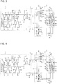
- Fig. 1 is a circuit diagram of an air-conditioning apparatus 1 according to Embodiment 1.
- the air-conditioning apparatus 1 will be described with reference to Fig. 1 .
- the air-conditioning apparatus 1 is intended for use in a building or a condominium, and utilizes a heat pump cycle, which is a refrigeration cycle in which refrigerant circulates, to perform a cooling and heating mixed operation.
- the air-conditioning apparatus 1 includes a controller 80 and a refrigerant circuit 2 in which a heat source-side unit 3 and a load-side unit group 5, including a plurality of load-side units, are connected to each other via a pipe and a relay unit 4.
- the heat source-side unit 3 and the relay unit 4 are connected to each other via a high-pressure pipe 72 and a low-pressure pipe 73.
- the relay unit 4 serves to switch the flow direction of the refrigerant flowing in from the high-pressure pipe 72 or the low-pressure pipe 73, to thereby allow each of the plurality of load-side units to independently perform a heating operation or a cooling operation.
- the relay unit 4 and the load-side unit group 5 are connected to each other via liquid pipes 79 and gas pipes 78.
- refrigerant examples include natural refrigerants such as carbon dioxide, hydrocarbon, and helium, chlorine-free fluorocarbon-substitute refrigerants such as HFC410A, HFC407C, and HFC404A, and fluorocarbon-based refrigerants used in conventional apparatuses such as R22 and R134a, among which a desired one may be selected.
- natural refrigerants such as carbon dioxide, hydrocarbon, and helium
- chlorine-free fluorocarbon-substitute refrigerants such as HFC410A, HFC407C, and HFC404A
- fluorocarbon-based refrigerants used in conventional apparatuses such as R22 and R134a, among which a desired one may be selected.
- the heat source-side unit 3 supplies cooling energy or heating energy to the load-side unit group 5.
- the heat source-side unit 3 includes a compressor 31 that compresses the refrigerant, a flow switching device 32 that switches the flow direction of the refrigerant, a heat source-side heat exchanger 34 that exchanges heat between a heat medium and the refrigerant, an accumulator 36 for storing liquid refrigerant, and a gas-liquid separator 33 that separates the refrigerant into gas refrigerant and liquid refrigerant.
- the compressor 31 sucks and compresses low-temperature, low-pressure gas refrigerant into high-temperature, high-pressure gas refrigerant, and discharges the gas refrigerant to the refrigerant circuit 2. Subsequently, the refrigerant circulates through the refrigerant circuit 2, so that the air-conditioning apparatus 1 performs an air-conditioning operation.
- the compressor 31, which thus serves to compress the sucked refrigerant into high-pressure refrigerant may be constituted of, for example, an inverter-based compressor configured to adjust the capacity.
- the compressor 31 may be, instead of the inverter-based compressor configured to adjust the capacity, a constant-speed compressor, or a compressor designed to perform both inverter control and constant speed control. Further, a reciprocating compressor, a rotary compressor, a scroll compressor, or a screw compressor may be employed as the compressor 31.
- the flow switching device 32 is located on the discharge side of the compressor 31, to switch the flow direction of the refrigerant between the heating operation and the cooling operation.
- the flow switching device 32 switches the flow direction of the refrigerant to cause the heat source-side heat exchanger 34 to act as evaporator in the heating operation, and to cause the heat source-side heat exchanger 34 to act as condenser in the cooling operation.
- a four-way valve may be employed as the flow switching device 32.
- the heat source-side heat exchanger 34 is connected to the flow switching device 32 via a first connection pipe 11, and exchanges heat between the refrigerant and a heat medium, for example, ambient outdoor air or water.
- a heat medium for example, ambient outdoor air or water.
- the heat source-side heat exchanger 34 acts as evaporator to evaporate and gasify the refrigerant
- the heat source-side heat exchanger 34 acts as condenser (radiator) to condense and liquefy the refrigerant.
- the heat source-side heat exchanger 34 is an air-cooled heat exchanger, and a heat source-side fan 35 is located close to the heat source-side heat exchanger 34.
- the heat source-side fan 35 serves to supply the outdoor air to the heat source-side heat exchanger 34, and the rotation speed of the heat source-side fan 35 is controlled to adjust the evaporation capacity or condensation capacity of the heat source-side heat exchanger 34.
- the heat source-side heat exchanger 34 is a water-cooled heat exchanger
- a water circulation pump is located close to the heat source-side heat exchanger 34, and the rotation speed of the water circulation pump is controlled to adjust the evaporation capacity or condensation capacity of the heat source-side heat exchanger 34.
- the accumulator 36 is located on the suction side of the compressor 31, to store a surplus of the refrigerant and separate the refrigerant into liquid refrigerant and gas refrigerant. Only the liquid refrigerant is stored in the accumulator 36, and the gas refrigerant passes through the accumulator 36 to be sucked into the compressor 31.
- the gas-liquid separator 33 is located between the heat source-side heat exchanger 34 and a separation pipe 73a branched from the low-pressure pipe 73 connecting between the heat source-side unit 3 and the relay unit 4, and is connected to the accumulator 36 via a bypass pipe 71.
- the gas-liquid separator 33 is directly connected to the suction side of the compressor 31, via the bypass pipe 71.
- the gas-liquid separator 33 separates the refrigerant flowing in from the high-pressure pipe 72 into liquid refrigerant and gas refrigerant, and sends the liquid refrigerant to the heat source-side heat exchanger 34 and the gas refrigerant to the bypass pipe 71.
- the gas-liquid separator 33 serves to prevent the gas refrigerant from flowing to the heat source-side heat exchanger 34 thereby minimizing degradation of heat exchange performance of the heat source-side heat exchanger 34.
- the gas-liquid separator 33 is provided in the separation pipe 73a branched from the low-pressure pipe 73.
- the gas-liquid separator 33 serves to prevent reduction in pressure in the low-pressure pipe 73 caused by a pressure loss generating in the gas-liquid separator 33 when the heat source-side heat exchanger 34 acts as condenser.
- the gas-liquid separator 33 may be located in the low-pressure pipe 73 when the separation pipe 73a is not provided.
- the gas-liquid separator 33 is not limited in its type and shape, and may be constituted of a desired type such as a gravity separation type and a centrifugal separation type, as long as two-phase refrigerant can be separated into gas phase and liquid phase. Further, the separation efficiency of the gas-liquid separator 33 may be selected as desired, depending on a liquid return amount, refrigerant circulation amount, target performance, or target cost specified by the system.
- the heat source-side unit 3 includes a plurality of connection pipes 10 and a plurality of check valves 20, to maintain a constant flow direction of the refrigerant flowing into the relay unit 4, irrespective of the operation requirement from the load-side unit group 5.
- the first check valve 21 serves to force the refrigerant flowing through the first connection pipe 11 to flow in the direction from the flow switching device 32 toward the heat source-side heat exchanger 34.
- An end of a second connection pipe 12 is connected to the outlet side of the heat source-side heat exchanger 34, and the second connection pipe 12 includes a second check valve 22.
- the second check valve 22 serves to force the refrigerant flowing through the second connection pipe 12 to flow in the direction from the heat source-side heat exchanger 34 toward each of the components.
- the second connection pipe 12 and the high-pressure pipe 72 are connected to each other via a third connection pipe 13, which includes a third check valve 23 and a fourth check valve 24.
- the third check valve 23 and the fourth check valve 24 serve to force the refrigerant flowing through the third connection pipe 13 to flow in the direction from the second connection pipe 12 toward the high-pressure pipe 72.
- the low-pressure pipe 73 connecting between the relay unit 4 and the flow switching device 32 includes a fifth check valve 25, which serves to force the refrigerant flowing through the low-pressure pipe 73 to flow in the direction from the relay unit 4 toward the flow switching device 32.
- the gas-liquid separator 33 and the third connection pipe 13 are connected to each other via a fourth connection pipe 14, which includes a sixth check valve 26.
- the sixth check valve 26 serves to force the refrigerant flowing through the fourth connection pipe 14 to flow in the direction from the gas-liquid separator 33 toward the third connection pipe 13.
- the third connection pipe 13 and the first connection pipe 11 are connected to each other via a fifth connection pipe 15, which includes a seventh check valve 27.
- the seventh check valve 27 serves to force the refrigerant flowing through the fifth connection pipe 15 to flow in the direction from the third connection pipe 13 toward the first connection pipe 11.
- the flow switching device 32 and the high-pressure pipe 72 are connected to each other via a sixth connection pipe 16, which includes an eighth check valve 28.
- the eighth check valve 28 serves to force the refrigerant flowing through the sixth connection pipe 16 to flow in the direction from the flow switching device 32 toward the high-pressure pipe 72.
- the second connection pipe 12 and the first connection pipe 11 are connected to each other via a seventh connection pipe 17, which includes a ninth check valve 29.
- the ninth check valve 29 serves to force the refrigerant flowing through the seventh connection pipe 17 to flow in the direction from the second connection pipe 12 toward the first connection pipe 11.
- the first connection pipe 11 includes a heat source-side on-off valve 38, and an expansion pipe 11 a connected parallel to the heat source-side on-off valve 38 includes a heat source-side expansion unit 39.
- the heat source-side on-off valve 38 When the heat source-side on-off valve 38 is opened, the refrigerant flows through the first connection pipe 11, and when the heat source-side on-off valve 38 is closed, the refrigerant is prevented from flowing through the first connection pipe 11.
- the opening degree of the heat source-side expansion unit 39 is adjustable, and hence the flow rate of the refrigerant flowing through the expansion pipe 11 a can be controlled with the opening degree.
- a pipe temperature in the load-side unit group 5, for example, the evaporation temperature of the load-side heat exchanger 51 provided in the load-side unit group 5, can be controlled.
- an electronic expansion valve may be employed as the heat source-side expansion unit 39.
- the bypass expansion unit 37 is located on the bypass pipe 71, to adjust the flow rate of the refrigerant flowing through the bypass pipe 71, with the opening degree of the bypass expansion unit 37.
- an electronic expansion valve may be employed as the bypass expansion unit 37.
- a discharge pressure detection unit 61 is provided on the discharge side of the compressor 31, to detect the discharge pressure of the refrigerant passing through the discharge side of the compressor 31.
- a suction pressure detection unit 62 is provided on the suction side of the compressor 31, to detect the suction pressure of the refrigerant passing through the suction side of the compressor 31.
- An inflow pressure detection unit 63 is provided to the separation pipe 73a, to detect the inflow pressure of the refrigerant flowing into the gas-liquid separator 33.
- the relay unit 4 distributes the refrigerant to each of the plurality of load-side units in the load-side unit group 5, and switches the flow direction of the refrigerant flowing in from the high-pressure pipe 72 or the low-pressure pipe 73.
- each of the plurality of load-side units can independently perform the heating operation or the cooling operation.
- the relay unit 4 includes a sub gas-liquid separator 41, a first refrigerant-to-refrigerant heat exchanger 42, a first refrigerant expansion unit 43, a second refrigerant-to-refrigerant heat exchanger 44, a second refrigerant expansion unit 45, and a refrigerant switch group 46.
- a sub bypass pipe 74 is connected, via the refrigerant switch group 46, to the gas pipes 78 connecting between the relay unit 4 and the load-side unit group 5, and the sub gas-liquid separator 41 is located between the high-pressure pipe 72 and the sub bypass pipe 74.
- the sub gas-liquid separator 41 and the liquid pipes 79, connecting between the relay unit 4 and the load-side unit group 5, are connected to each other via a primary-side pipe 75.
- the sub gas-liquid separator 41 separates the refrigerant flowing in from the low-pressure pipe 73 into gas refrigerant and liquid refrigerant, and sends the gas refrigerant to the sub bypass pipe 74 and the liquid refrigerant to the primary-side pipe 75.
- the sub gas-liquid separator 41 is not limited in its type and shape, and may be constituted of a desired type such as a gravity separation type and a centrifugal separation type, as long as two-phase refrigerant can be separated into gas phase and liquid phase. Further, the separation efficiency of the sub gas-liquid separator 41 may be selected as desired, depending on a liquid return amount, refrigerant circulation amount, target performance, or target cost specified by the system.
- a secondary-side pipe 76 is further provided at the joint between the primary-side pipe 75 and the liquid pipes 79.
- the secondary-side pipe 76 is connected to the low-pressure pipe 73.
- the first refrigerant-to-refrigerant heat exchanger 42 is located on the outlet side of the sub gas-liquid separator 41 in the primary-side pipe 75, to exchange heat between the liquid refrigerant flowing out of the sub gas-liquid separator 41 in the primary-side pipe 75 and the refrigerant flowing through the secondary-side pipe 76.
- the first refrigerant expansion unit 43 is located on the outlet side of the first refrigerant-to-refrigerant heat exchanger 42 in the primary-side pipe 75, to depressurize and expand the refrigerant flowing through the primary-side pipe 75.
- the first refrigerant expansion unit 43 is configured to serve as reducing valve or expansion valve, and may be constituted of, for example, an elaborate flow control device such as an electronic expansion valve with variable opening degree, or an inexpensive flow control device such as capillary tubes.
- the second refrigerant-to-refrigerant heat exchanger 44 is located on the outlet side of the first refrigerant expansion unit 43 in the primary-side pipe 75, to exchange heat between the refrigerant flowing out of the first refrigerant expansion unit 43 in the primary-side pipe 75 and the refrigerant flowing through the secondary-side pipe 76.
- the second refrigerant expansion unit 45 is located on the outlet side of the second refrigerant-to-refrigerant heat exchanger 44 in the secondary-side pipe 76, to depressurize and expand the refrigerant flowing through the secondary-side pipe 76.
- the second refrigerant expansion unit 45 is configured to serve as reducing valve or expansion valve, and may be constituted of, for example, an elaborate flow control device such as an electronic expansion valve with variable opening degree, or an inexpensive flow control device such as capillary tubes.
- the first refrigerant-to-refrigerant heat exchanger 42, the first refrigerant expansion unit 43, the second refrigerant-to-refrigerant heat exchanger 44, and the second refrigerant expansion unit 45 allow the refrigerant flowing through the primary-side pipe 75 and the refrigerant flowing through the secondary-side pipe 76 to exchange heat with each other, so that the refrigerant flowing through the primary-side pipe 75 can be subcooled.
- Optimizing the opening degree of the second refrigerant expansion unit 45 enables the refrigerant flowing through the primary-side pipe 75 to be properly subcooled.
- the refrigerant switch group 46 includes a plurality of refrigerant switches whose number is the same as the number of the load-side units.
- the refrigerant switch group 46 serves to allow the refrigerant to flow and prevent the refrigerant from flowing.
- the load-side unit group 5 includes a first load-side unit 5a and a second load-side unit 5b
- the refrigerant switch group 46 includes a first refrigerant switch 47 and a second refrigerant switch 48, correspondingly.
- the first refrigerant switch 47 includes an eleventh refrigerant switch 47a and a twelfth refrigerant switch 47b connected in parallel.
- the eleventh refrigerant switch 47a is connected to the sub gas-liquid separator 41 via the sub bypass pipe 74, and the twelfth refrigerant switch 47b is connected to the secondary low-pressure pipe 77 additionally provided to the joint between the secondary-side pipe 76 and the low-pressure pipe 73.
- the eleventh refrigerant switch 47a and the twelfth refrigerant switch 47b are configured to work in linkage with each other, so that when the eleventh refrigerant switch 47a is opened, the twelfth refrigerant switch 47b is closed.
- the sub bypass pipe 74 communicates with one of the gas pipes 78, so that the refrigerant flows between the sub gas-liquid separator 41 and the first load-side unit 5a.
- the eleventh refrigerant switch 47a is closed, the twelfth refrigerant switch 47b is opened.
- the secondary low-pressure pipe 77 communicates with one of the gas pipes 78, so that the refrigerant flows between the heat source-side unit 3 and the first load-side unit 5a.
- the second refrigerant switch 48 includes a twenty-first refrigerant switch 48a and a twenty-second refrigerant switch 48b connected in parallel.
- the twenty-first refrigerant switch 48a is connected to the sub gas-liquid separator 41 via the sub bypass pipe 74, and the twenty-second refrigerant switch 48b is connected to the secondary low-pressure pipe 77 additionally provided to the joint between the secondary-side pipe 76 and the low-pressure pipe 73.
- the twenty-first refrigerant switch 48a and the twenty-second refrigerant switch 48b are configured to work in linkage with each other, so that when the twenty-first refrigerant switch 48a is opened, the twenty-second refrigerant switch 48b is closed.
- the sub bypass pipe 74 communicates with one of the gas pipes 78, so that the refrigerant flows between the sub gas-liquid separator 41 and the second load-side unit 5b.
- the twenty-first refrigerant switch 48a is closed, the twenty-second refrigerant switch 48b is opened.
- the secondary low-pressure pipe 77 communicates with one of the gas pipes 78, so that the refrigerant flows between the heat source-side unit 3 and the second load-side unit 5b.
- the load-side unit group 5 receives cooling energy or heating energy from the heat source-side unit 3 to process the cooling load or the heating load, and includes a plurality of load-side heat exchangers 51, a plurality of expansion units 52, a plurality of gas pipe temperature detection units 64, and a plurality of liquid pipe temperature detection units 65. As stated above, the load-side unit group 5 includes the first load-side unit 5a and the second load-side unit 5b.
- the load-side heat exchangers 51 include a first load-side heat exchanger 51 a and a second load-side heat exchanger 51 b
- the expansion units 52 include a first expansion unit 52a and a second expansion unit 52b
- the gas pipe temperature detection units 64 include a first gas pipe temperature detection unit 64a and a second gas pipe temperature detection unit 64b
- the liquid pipe temperature detection units 65 include a first liquid pipe temperature detection unit 65a and a second liquid pipe temperature detection unit 65b.
- Each of the plurality of load-side heat exchangers 51 can independently act as condenser or evaporator.
- the first load-side unit 5a has one end connected to the first gas pipe 78a and the other end connected to the first liquid pipe 79a.
- the first load-side unit 5a includes a first load-side heat exchanger 51 a, a first expansion unit 52a, a first gas pipe temperature detection unit 64a, and a first liquid pipe temperature detection unit 65a.
- the first load-side heat exchanger 51 a is connected to the first gas pipe 78a, and exchanges heat between the refrigerant and a heat medium, for example, ambient room air or water.
- a heat medium for example, ambient room air or water.
- the first load-side heat exchanger 51 a acts as evaporator to evaporate and gasify the refrigerant
- the first load-side heat exchanger 51 a acts as condenser (radiator) to condense and liquefy the refrigerant.
- the first load-side heat exchanger 51 a is an air-cooled heat exchanger, and a non-illustrated first load-side fan is located close to the first load-side heat exchanger 51 a.
- the first load-side fan serves to supply the room air to the first load-side heat exchanger 51 a, and the rotation speed of the first load-side fan is controlled to adjust the evaporation capacity or condensation capacity of the first load-side heat exchanger 51 a.
- a water circulation pump is located close to the first load-side heat exchanger 51 a, and the rotation speed of the water circulation pump is controlled to adjust the evaporation capacity or condensation capacity of the first load-side heat exchanger 51 a.
- the first expansion unit 52a is provided in the first liquid pipe 79a, to depressurize and expand the refrigerant flowing through the first liquid pipe 79a.
- the first expansion unit 52a is configured to serve as reducing valve or expansion valve, and may be constituted of, for example, an elaborate flow control device such as an electronic expansion valve with variable opening degree, or an inexpensive flow control device such as capillary tubes.
- the first gas pipe temperature detection unit 64a is located in the first gas pipe 78a at a position close to the first load-side heat exchanger 51 a, to detect the temperature of the refrigerant flowing through the first gas pipe 78a.
- the eleventh refrigerant switch 47a is closed and the twelfth refrigerant switch 47b is opened, the refrigerant flows between the heat source-side unit 3 and the first load-side unit 5a.
- the first load-side heat exchanger 51 a acts as evaporator in this state, the refrigerant flowing out of the first load-side heat exchanger 51 a flows into the gas-liquid separator 33.
- the first gas pipe temperature detection unit 64a acts as first inflow temperature detection unit that detects the inflow temperature of the refrigerant flowing into the gas-liquid separator 33.
- the first liquid pipe temperature detection unit 65a is located in the first liquid pipe 79a at a position close to the first load-side heat exchanger 51 a, to detect the temperature of the refrigerant flowing through the first liquid pipe 79a.
- the second load-side unit 5b has one end connected to the second gas pipe 78b and the other end connected to the second liquid pipe 79b.
- the second load-side unit 5b includes a second load-side heat exchanger 51 b, a second expansion unit 52b, a second gas pipe temperature detection unit 64b, and a second liquid pipe temperature detection unit 65b.
- the second load-side heat exchanger 51 b is connected to the second gas pipe 78b, and exchanges heat between the refrigerant and a heat medium, for example, ambient room air or water.
- a heat medium for example, ambient room air or water.
- the second load-side heat exchanger 51 b acts as evaporator to evaporate and gasify the refrigerant
- the second load-side heat exchanger 51 b acts as condenser (radiator) to condense and liquefy the refrigerant.
- the second load-side heat exchanger 51 b is an air-cooled heat exchanger, and a non-illustrated second load-side fan is located close to the second load-side heat exchanger 51 b.
- the second load-side fan serves to supply the room air to the second load-side heat exchanger 51 b, and the rotation speed of the second load-side fan is controlled to adjust the evaporation capacity or condensation capacity of the second load-side heat exchanger 51 b.
- the second load-side heat exchanger 51 b is a water-cooled heat exchanger
- a water circulation pump is located close to the second load-side heat exchanger 51 b, and the rotation speed of the water circulation pump is controlled to adjust the evaporation capacity or condensation capacity of the second load-side heat exchanger 51 b.
- the second expansion unit 52b is provided in the second liquid pipe 79b, to depressurize and expand the refrigerant flowing through the second liquid pipe 79b.
- the second expansion unit 52b is configured to serve as reducing valve or expansion valve, and may be constituted of, for example, an elaborate flow control device such as an electronic expansion valve with variable opening degree, or an inexpensive flow control device such as capillary tubes.
- the second gas pipe temperature detection unit 64b is located in the second gas pipe 78b at a position close to the second load-side heat exchanger 51 b, to detect the temperature of the refrigerant flowing through the second gas pipe 78b.
- the twenty-first refrigerant switch 48a is closed and the twenty-second refrigerant switch 48b is opened, the refrigerant flows between the heat source-side unit 3 and the second load-side unit 5b.
- the second load-side heat exchanger 51 b acts as evaporator in this state, the refrigerant flowing out of the second load-side heat exchanger 51 b flows into the gas-liquid separator 33.
- the second gas pipe temperature detection unit 64b acts as second inflow temperature detection unit that detects the inflow temperature of the refrigerant flowing into the gas-liquid separator 33.
- the second liquid pipe temperature detection unit 65b is located in the second liquid pipe 79b at a position close to the second load-side heat exchanger 51 b, to detect the temperature of the refrigerant flowing through the second liquid pipe 79b.
- the controller 80 is, for example, provided in the heat source-side unit 3, to control the operation of the refrigerant circuit 2.
- the controller 80 controls, for example, the driving frequency of the compressor 31, the rotation speed of the heat source-side fan 35, and the switching of the flow switching device 32, on the basis of the discharge pressure detected by the discharge pressure detection unit 61, the suction pressure detected by the suction pressure detection unit 62, and other related factors.
- the controller 80 controls the state of the actuators, for example, the degree of the opening of the first expansion unit 52a, the opening degree of the second expansion unit 52b, the rotation speed of the non-illustrated first load-side fan, and the rotation speed of the non-illustrated second load-side fan, on the basis of the first gas pipe temperature detected by the first gas pipe temperature detection unit 64a, the second gas pipe temperature detected by the second gas pipe temperature detection unit 64b, the first liquid pipe temperature detected by the first liquid pipe temperature detection unit 65a, the second liquid pipe temperature detected by the second liquid pipe temperature detection unit 65b, and other related factors.
- the controller 80 may be provided in the relay unit 4, or in the load-side unit group 5. Alternatively, the controller 80 may be provided outside the heat source-side unit 3, the relay unit 4, and the load-side unit group 5.
- the controller 80 may be divided into a plurality of units by the functions or other factors, and each of such units may be provided to a corresponding one of the heat source-side unit 3, the relay unit 4, and the load-side unit group 5. In this case, the units of the controller 80 are configured to communicate with one another, via wired or wireless communication.
- the controller 80 also serves to control the opening degree of the bypass expansion unit 37, on the basis of the bypass flow rate of the refrigerant flowing through the bypass pipe 71, the inflow flow rate of the refrigerant flowing into the gas-liquid separator 33, and the inlet quality of the gas-liquid separator 33. In other words, the controller 80 determines whether the amount of the gas refrigerant flowing into the gas-liquid separator 33 is equal to the amount of the gas refrigerant flowing into the bypass pipe 71, and adjusts the opening degree of the bypass expansion unit 37 on the basis of the determination result.
- Fig. 2 is a block diagram showing a configuration of the controller 80 of the air-conditioning apparatus 1 according to Embodiment 1. As shown in Fig. 2 , the controller 80 includes a threshold determination unit 81, a heat source opening degree adjustment unit 82, a first determination unit 83, a second determination unit 84, and a bypass opening degree adjustment unit 85.
- the threshold determination unit 81 determines whether the liquid pipe temperature detected by the liquid pipe temperature detection unit 65 is equal to or lower than a predetermined threshold of the liquid pipe temperature.
- the threshold of the liquid pipe temperature may be altered as desired.
- the heat source opening degree adjustment unit 82 adjusts the opening degree of the heat source-side expansion unit 39 to make the liquid pipe temperature higher than the threshold of the liquid pipe temperature, when the threshold determination unit 81 determines that the liquid pipe temperature is equal to or lower than the threshold of the liquid pipe temperature.
- the heat source-side expansion unit 39 serves to adjust the flow rate of the refrigerant flowing through the expansion pipe 11 a, by controlling the opening degree, to adjust the pipe temperature in the load-side unit group 5, for example, the temperature of the liquid pipe located in the vicinity of the load-side heat exchanger 51 in the load-side unit group 5.
- the heat source opening degree adjustment unit 82 may adjust the opening degree of the heat source-side expansion unit 39 even in a case where the threshold determination unit 81 does not detect the liquid pipe temperature.
- the first determination unit 83 determines whether the bypass flow rate is different from a multiplied value obtained by multiplying the inflow flow rate by the inlet quality.
- the bypass flow rate of the refrigerant flowing through the bypass pipe 71 will be described below.
- the bypass flow rate is calculated by the first determination unit 83 on the basis of the suction pressure detected by the suction pressure detection unit 62, the inflow pressure detected by the inflow pressure detection unit 63, and the opening degree of the heat source-side expansion unit 39.
- the inflow pressure is denoted by P1
- the suction pressure is denoted by P2
- the flow path resistance obtained from the opening degree of the heat source-side expansion unit 39 is denoted by Cv
- the specific gravity is denoted by G
- the density is denoted by p
- the bypass flow rate Grg can be obtained through the following equation (1).
- Grg 17 ⁇ Cv ⁇ ⁇ ⁇ P 1 + P 2 ⁇ P 2 ⁇ P 1 1 / 2 / G 1 / 2
- the inflow flow rate of the refrigerant flowing into the gas-liquid separator 33 will be described next.
- the inflow flow rate is calculated by the first determination unit 83 on the basis of performance of the compressor 31.
- Vst the stroke volume of the compressor 31
- ⁇ v the volume efficiency of the compressor 31
- F the frequency of the compressor 31
- ps the suction density of the compressor 31
- Gr 3600 ⁇ Vst ⁇ ⁇ v ⁇ F ⁇ ⁇ s
- the inlet quality of the gas-liquid separator 33 will be described below.
- the inlet quality is calculated by the first determination unit 83 on the basis of the discharge pressure detected by the discharge pressure detection unit 61, the suction pressure detected by the suction pressure detection unit 62, and the inflow temperature detected by the inflow temperature detection unit.
- ho saturated liquid enthalpy calculated from the suction pressure
- hg saturated gas enthalpy calculated from the suction pressure
- the first determination unit 83 determines whether the separation efficiency between the gas refrigerant and the liquid refrigerant in the gas-liquid separator 33 is optimum, by determining whether the bypass flow rate is different from the multiplied value obtained by multiplying the inflow flow rate by the inlet quality.
- the second determination unit 84 determines whether the bypass flow rate is higher than the multiplied value, when the first determination unit 83 determines that the bypass flow rate is different from the multiplied value. In other words, the second determination unit 84 determines whether the bypass flow rate is higher than the multiplied value, when the first determination unit 83 determines that the separation efficiency between the gas refrigerant and the liquid refrigerant in the gas-liquid separator 33 is not optimum.
- the bypass opening degree adjustment unit 85 reduces the opening degree of the bypass expansion unit 37, when the second determination unit 84 determines that the bypass flow rate is higher than the multiplied value.
- the bypass flow rate is higher than the multiplied value (Grg > Gr ⁇ x)
- a liquid return phenomenon where the liquid refrigerant flows through the bypass pipe 71, occurs.
- the bypass opening degree adjustment unit 85 reduces the opening degree of the bypass expansion unit 37 in the bypass pipe 71, to thereby reduce the bypass flow rate in the bypass pipe 71.
- the bypass opening degree adjustment unit 85 increases the opening degree of the bypass expansion unit 37, when the second determination unit 84 determines that the bypass flow rate is lower than the multiplied value.
- the bypass pipe 71 still has a room for the gas refrigerant to flow into the bypass pipe 71.
- the bypass opening degree adjustment unit 85 increases the opening degree of the bypass expansion unit 37 in the bypass pipe 71, to thereby increase the bypass flow rate in the bypass pipe 71.
- the air-conditioning apparatus 1 performs an air-conditioning operation when the air-conditioning apparatus 1 receives an operation request, for example, transmitted from a remote controller provided in the room.
- the air-conditioning operation modes of the air-conditioning apparatus 1 include the heating operation in which the heat source-side heat exchanger 34 acts as evaporator, and the cooling operation in which the heat source-side heat exchanger 34 acts as condenser.
- the heating operation includes a heating-only operation in which all of the load-side heat exchangers 51 act as condenser, and a heating-main operation in which at least one of the load-side heat exchangers 51 acts as evaporator.
- the heating-main operation refers to an operation mode in which the heating load is heavier than the cooling load, in a cooling and heating mixed operation.
- the cooling operation includes a cooling-only operation in which all of the load-side heat exchangers 51 act as evaporator, and a cooling-main operation in which at least one of the load-side heat exchangers 51 acts as condenser.
- the cooling-main operation refers to an operation mode in which the cooling load is heavier than the heating load, in the cooling and heating mixed operation.
- Fig. 3 is a circuit diagram representing the heating-only operation according to Embodiment 1.
- both of the first load-side unit 5a and the second load-side unit 5b perform the heating operation, in other words, both of the first load-side heat exchanger 51 a and the second load-side heat exchanger 51 b act as condenser.
- the eleventh refrigerant switch 47a is opened and the twelfth refrigerant switch 47b is closed.
- the twenty-first refrigerant switch 48a is also opened and hence the twenty-second refrigerant switch 48b is closed.
- the first load-side unit 5a and the second load-side unit 5b are connected in parallel.
- the heat source-side on-off valve 38 is opened and the heat source-side expansion unit 39 is closed.
- the compressor 31 sucks and compresses the refrigerant and discharges the refrigerant in a state of high-temperature, high-pressure gas.
- the discharged refrigerant passes through the flow switching device 32 and the sixth connection pipe 16, and then reaches the high-pressure pipe 72.
- the refrigerant then flows into the sub gas-liquid separator 41 from the high-pressure pipe 72, and the gas refrigerant flows out to the sub bypass pipe 74 while the liquid refrigerant flows out to the primary-side pipe 75.
- the gas refrigerant flowing out to the sub bypass pipe 74 is branched, and each of the branched portions passes through a corresponding one of the eleventh refrigerant switch 47a and the twenty-first refrigerant switch 48a.
- Each of the branched portions then flows into a corresponding one of the first load-side heat exchanger 51 a and the second load-side heat exchanger 51 b, through a corresponding one of the first gas pipe 78a and the second gas pipe 78b.
- each of the first load-side heat exchanger 51 a and the second load-side heat exchanger 51 b exchanges heat with the room air supplied by a corresponding one of the first load-side fan and the second load-side fan, thereby condensing the refrigerant.
- the air in each room is heated and thus each room space is heated.
- Each of the condensed branched portions of refrigerant flows into a corresponding one of the first expansion unit 52a and the second expansion unit 52b, in each of which the condensed refrigerant is depressurized.
- the depressurized branched portions of refrigerant flows into the second refrigerant-to-refrigerant heat exchanger 44 through a corresponding one of the first liquid pipe 79a and the second liquid pipe 79b, thus to be merged.
- the liquid refrigerant flowing out to the primary-side pipe 75 from the sub gas-liquid separator 41 flows into the first refrigerant-to-refrigerant heat exchanger 42, and the first refrigerant-to-refrigerant heat exchanger 42 exchanges heat with the refrigerant flowing through the secondary-side pipe 76, to thereby condense the refrigerant flowing through the primary-side pipe 75.
- the condensed refrigerant flows into the first refrigerant expansion unit 43, in which the condensed refrigerant is depressurized.
- the depressurized refrigerant then flows into the second refrigerant-to-refrigerant heat exchanger 44, and is merged with the refrigerant flowing in through the first liquid pipe 79a and the second liquid pipe 79b.
- the second refrigerant-to-refrigerant heat exchanger 44 exchanges heat with the refrigerant flowing through the secondary-side pipe 76, to thereby condense the refrigerant flowing through the primary-side pipe 75.
- the condensed refrigerant flows into the second refrigerant expansion unit 45 through the secondary-side pipe 76, and the second refrigerant expansion unit 45 depressurizes the condensed refrigerant.
- the refrigerant flowing through the primary-side pipe 75 is subcooled.
- the refrigerant flowing through the secondary-side pipe 76 then passes through the low-pressure pipe 73 and also the separation pipe 73a, and flows into the gas-liquid separator 33.
- the gas-liquid separator 33 separates the refrigerant flowing in from the separation pipe 73a into the gas refrigerant and the liquid refrigerant.
- the gas refrigerant flows out to the bypass pipe 71, and the liquid refrigerant flows out to the fourth connection pipe 14.
- the gas refrigerant flows into the accumulator 36 through the bypass pipe 71, and is then sucked into the compressor 31.
- the liquid refrigerant flowing out to the third connection pipe 13 flows into the heat source-side heat exchanger 34 through the fifth connection pipe 15.
- the heat source-side heat exchanger 34 exchanges heat with the outside air supplied by the heat source-side fan 35, to thereby evaporate the refrigerant.
- the evaporated refrigerant passes through the second connection pipe 12 and then the seventh connection pipe 17, and reaches the flow switching device 32.
- the refrigerant then flows into the accumulator 36 and is sucked into the compressor 31.
- Fig. 4 is a circuit diagram representing the heating-main operation according to Embodiment 1.
- the first load-side unit 5a performs the heating operation while the second load-side unit 5b performs the cooling operation.
- the first load-side heat exchanger 51 a acts as condenser and the second load-side heat exchanger 51 b acts as evaporator.
- the eleventh refrigerant switch 47a is opened and the twelfth refrigerant switch 47b is closed.
- the twenty-first refrigerant switch 48a is closed and the twenty-second refrigerant switch 48b is opened.
- first load-side unit 5a and the second load-side unit 5b are connected in series.
- the heat source-side on-off valve 38 is opened and the heat source-side expansion unit 39 is closed.
- the first load-side unit 5a may be set to perform the cooling operation and the second load-side unit 5b may be set to perform the heating operation.
- the compressor 31 sucks and compresses the refrigerant and discharges the refrigerant in a state of high-temperature, high-pressure gas.
- the discharged refrigerant passes through the flow switching device 32 and the sixth connection pipe 16, and then reaches the high-pressure pipe 72.
- the refrigerant then flows into the sub gas-liquid separator 41 from the high-pressure pipe 72, and the gas refrigerant flows out to the sub bypass pipe 74 while the liquid refrigerant flows out to the primary-side pipe 75.
- the gas refrigerant flowing out to the sub bypass pipe 74 flows through the eleventh refrigerant switch 47a.
- the refrigerant switch 48a Since the twenty-first refrigerant switch 48a is closed at this point, the refrigerant is prevented from flowing through the twenty-first refrigerant switch 48a.
- the refrigerant then flows into the first load-side heat exchanger 51 a through the first gas pipe 78a.
- the first load-side heat exchanger 51 a exchanges heat with the room air supplied by the first load-side fan, thereby condensing the refrigerant.
- the air in the room is heated and thus the room space is heated.
- the condensed refrigerant flows into the first expansion unit 52a, in which the condensed refrigerant is depressurized.
- the depressurized refrigerant flows into the second refrigerant-to-refrigerant heat exchanger 44 through the first liquid pipe 79a. Since the twenty-second refrigerant switch 48b is opened at this point, a portion of the refrigerant flows into the second liquid pipe 79b.
- the refrigerant entering the second liquid pipe 79b flows into the second expansion unit 52b, in which the refrigerant is depressurized.
- the depressurized refrigerant flows into the second load-side heat exchanger 51 b, and the second load-side heat exchanger 51 b exchanges heat with the room air supplied by the second load-side fan, to thereby evaporate the refrigerant.
- the room air is cooled and thus the room space is cooled.
- the evaporated refrigerant flows through the second gas pipe 78b and then the twenty-second refrigerant switch 48b, and reaches the low-pressure pipe 73.
- the liquid refrigerant flowing out to the primary-side pipe 75 from the sub gas-liquid separator 41 flows into the first refrigerant-to-refrigerant heat exchanger 42, and the first refrigerant-to-refrigerant heat exchanger 42 exchanges heat with the refrigerant flowing through the secondary-side pipe 76, to thereby condense the refrigerant flowing through the primary-side pipe 75.
- the condensed refrigerant flows into the first refrigerant expansion unit 43, in which the condensed refrigerant is depressurized.
- the depressurized refrigerant then flows into the second refrigerant-to-refrigerant heat exchanger 44, and is merged with the refrigerant flowing in through the first liquid pipe 79a.
- the second refrigerant-to-refrigerant heat exchanger 44 exchanges heat with the refrigerant flowing through the secondary-side pipe 76, to thereby condense the refrigerant flowing through the primary-side pipe 75.
- the condensed refrigerant flows into the second refrigerant expansion unit 45 through the secondary-side pipe 76, and the second refrigerant expansion unit 45 depressurizes the condensed refrigerant.
- the refrigerant flowing through the primary-side pipe 75 is subcooled.
- the refrigerant flowing through the secondary-side pipe 76 is then merged with the refrigerant from the second gas pipe 78b, and reaches the low-pressure pipe 73. Then the refrigerant passes through the separation pipe 73a and flows into the gas-liquid separator 33.
- the gas-liquid separator 33 separates the refrigerant flowing in from the separation pipe 73a into the gas refrigerant and the liquid refrigerant.
- the gas refrigerant flows out to the bypass pipe 71, and the liquid refrigerant flows out to the fourth connection pipe 14.
- the gas refrigerant flows into the accumulator 36 through the bypass pipe 71, and is then sucked into the compressor 31.
- the liquid refrigerant flowing out to the third connection pipe 13 flows into the heat source-side heat exchanger 34 through the fifth connection pipe 15.
- the heat source-side heat exchanger 34 exchanges heat with the outside air supplied by the heat source-side fan 35, to thereby evaporate the refrigerant.
- the evaporated refrigerant passes through the second connection pipe 12 and then the seventh connection pipe 17, and reaches the flow switching device 32.
- the refrigerant then flows into the accumulator 36 and is sucked into the compressor 31.
- Fig. 5 is a circuit diagram representing the cooling-only operation according to Embodiment 1.
- both of the first load-side unit 5a and the second load-side unit 5b perform the cooling operation, in other words, both of the first load-side heat exchanger 51 a and the second load-side heat exchanger 51 b act as evaporator.
- the eleventh refrigerant switch 47a is closed and the twelfth refrigerant switch 47b is opened.
- the twenty-first refrigerant switch 48a is also closed and hence the twenty-second refrigerant switch 48b is opened.
- the first load-side unit 5a and the second load-side unit 5b are connected in parallel.
- the heat source-side on-off valve 38 is opened and the heat source-side expansion unit 39 is closed.
- the compressor 31 sucks and compresses the refrigerant and discharges the refrigerant in a state of high-temperature, high-pressure gas.
- the discharged refrigerant passes through the flow switching device 32 and flows into the heat source-side heat exchanger 34 through the first connection pipe 11.
- the heat source-side heat exchanger 34 exchanges heat with the outside air supplied from the heat source-side fan 35, to thereby condense the refrigerant.
- the condensed refrigerant sequentially passes through the second connection pipe 12 and the third connection pipe 13, and reaches the high-pressure pipe 72. From the high-pressure pipe 72, the refrigerant flows into the sub gas-liquid separator 41. Since the eleventh refrigerant switch 47a and the twenty-first refrigerant switch 48a are closed at this point, the refrigerant is prevented from flowing in the sub bypass pipe 74 and only allowed to flow through the primary-side pipe 75.
- the refrigerant flowing out to the primary-side pipe 75 flows into the first refrigerant-to-refrigerant heat exchanger 42, which exchanges heat with the refrigerant flowing through the secondary-side pipe 76, to thereby condense the refrigerant flowing through the primary-side pipe 75.
- the condensed refrigerant flows into the first refrigerant expansion unit 43, in which the condensed refrigerant is depressurized.
- the depressurized refrigerant flows into the second refrigerant-to-refrigerant heat exchanger 44, which exchanges heat with the refrigerant flowing through the secondary-side pipe 76, to thereby condense the refrigerant flowing through the primary-side pipe 75.
- the refrigerant flowing through the primary-side pipe 75 is subcooled.
- the refrigerant condensed in the second refrigerant-to-refrigerant heat exchanger 44 is branched, and each of the branched portions flows through a corresponding one of the first liquid pipe 79a, the second liquid pipe 79b, and the secondary-side pipe 76.
- Each of the portions of the refrigerant entering the first liquid pipe 79a and the second liquid pipe 79b flows into a corresponding one of the first expansion unit 52a and the second expansion unit 52b, each of which depressurizes the refrigerant.
- the depressurized refrigerant then flows into the first load-side heat exchanger 51 a and the second load-side heat exchanger 51 b, each of which exchanges heat with the room air supplied from the first load-side fan and the second load-side fan, to thereby evaporate the refrigerant.
- the air in each room is cooled and thus each room space is cooled.
- Each of the portions of the evaporated refrigerant flows through a corresponding one of the first gas pipe 78a and the second gas pipe 78b and passes through a corresponding one of the twelfth refrigerant switch 47b and the twenty-second refrigerant switch 48b, to be then merged and reach the low-pressure pipe 73.
- the refrigerant flowing through the secondary-side pipe 76 from the second refrigerant-to-refrigerant heat exchanger 44 flows into the second refrigerant expansion unit 45, in which the condensed refrigerant is depressurized.
- the depressurized refrigerant flows through the secondary-side pipe 76 and is merged with the portions of the refrigerant from the first gas pipe 78a and the second gas pipe 78b, and then reaches the low-pressure pipe 73.
- the refrigerant flowing through the low-pressure pipe 73 flows into the accumulator 36 through the flow switching device 32, and is then sucked into the compressor 31.
- Fig. 6 is a circuit diagram representing the cooling-main operation according to Embodiment 1.
- the first load-side unit 5a performs the cooling operation while the second load-side unit 5b performs the heating operation.
- the first load-side heat exchanger 51 a acts as evaporator and the second load-side heat exchanger 51 b acts as condenser.
- the eleventh refrigerant switch 47a is closed and the twelfth refrigerant switch 47b is opened.
- the twenty-first refrigerant switch 48a is opened and the twenty-second refrigerant switch 48b is closed.
- first load-side unit 5a and the second load-side unit 5b are connected in series.
- the heat source-side on-off valve 38 is opened and the heat source-side expansion unit 39 is closed.
- the first load-side unit 5a may be set to perform the heating operation and the second load-side unit 5b may be set to perform the cooling operation.
- the compressor 31 sucks and compresses the refrigerant and discharges the refrigerant in a state of high-temperature, high-pressure gas.
- the discharged refrigerant passes through the flow switching device 32 and flows into the heat source-side heat exchanger 34 through the first connection pipe 11.
- the heat source-side heat exchanger 34 exchanges heat with the outside air supplied from the heat source-side fan 35, to thereby condense the refrigerant.
- the condensed refrigerant sequentially passes through the second connection pipe 12 and the third connection pipe 13, and reaches the high-pressure pipe 72. From the high-pressure pipe 72, the refrigerant flows into the sub gas-liquid separator 41.
- the gas refrigerant flows out to the sub bypass pipe 74, while the liquid refrigerant flows out to the primary-side pipe 75. Since the eleventh refrigerant switch 47a is closed at this point, the gas refrigerant is prevented from flowing in the eleventh refrigerant switch 47a. However, since the twenty-first refrigerant switch 48a is opened, the gas refrigerant flows through the twenty-first refrigerant switch 48a.
- the refrigerant flowing out to the primary-side pipe 75 flows into the first refrigerant-to-refrigerant heat exchanger 42, and the first refrigerant-to-refrigerant heat exchanger 42 exchanges heat with the refrigerant flowing through the secondary-side pipe 76, to thereby condense the refrigerant flowing through the primary-side pipe 75.
- the condensed refrigerant flows into the first refrigerant expansion unit 43, in which the condensed refrigerant is depressurized.
- the depressurized refrigerant then flows into the second refrigerant-to-refrigerant heat exchanger 44, which exchanges heat with the refrigerant flowing through the secondary-side pipe 76, to thereby condense the refrigerant flowing through the primary-side pipe 75.
- the refrigerant flowing through the primary-side pipe 75 is subcooled.
- the refrigerant condensed in the second refrigerant-to-refrigerant heat exchanger 44 is branched to flow into the first liquid pipe 79a and the secondary-side pipe 76.
- the refrigerant entering the first liquid pipe 79a flows into the first expansion unit 52a, which depressurizes the refrigerant.
- the depressurized refrigerant then flows into the first load-side heat exchanger 51 a, which exchanges heat with the room air supplied from the first load-side fan, to thereby evaporate the refrigerant.
- the evaporated refrigerant flows through the first gas pipe 78a and the twelfth refrigerant switch 47b, and reaches the low-pressure pipe 73.
- the refrigerant flowing out to the sub bypass pipe 74 flows through the twenty-first refrigerant switch 48a, and then flows into the second load-side heat exchanger 51 b through the second gas pipe 78b.
- the second load-side heat exchanger 51 b exchanges heat with the room air supplied from the second load-side fan, to thereby condense the refrigerant.
- the condensed refrigerant flows into the second expansion unit 52b, which depressurizes the condensed refrigerant.
- the depressurized refrigerant flows into the second refrigerant-to-refrigerant heat exchanger 44 through the second liquid pipe 79b.
- the refrigerant flowing through the secondary-side pipe 76 from the second refrigerant-to-refrigerant heat exchanger 44 is merged with the refrigerant from the second liquid pipe 79b.
- the merged refrigerant flows into the second refrigerant expansion unit 45, in which the condensed refrigerant is depressurized.
- the depressurized refrigerant flows through the secondary-side pipe 76 and is merged with the refrigerant from the first gas pipe 78a, and then reaches the low-pressure pipe 73.
- the refrigerant flowing through the low-pressure pipe 73 flows into the accumulator 36 through the flow switching device 32, and is then sucked into the compressor 31.
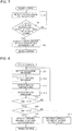
- Fig. 7 is a flowchart showing the operation of the air-conditioning apparatus 1 according to Embodiment 1.
- a dual evaporation temperature control may be performed in the heating-main operation in which the ratio of the heating load is greater.
- the heat source-side on-off valve 38 provided on the inlet side of the heat source-side heat exchanger 34 of the heat source-side unit 3, acting as evaporator, is closed, when the liquid pipe temperature of the load-side unit currently performing the cooling operation is equal to or lower than a predetermined temperature, and the opening degree of the heat source-side expansion unit 39 located parallel to the heat source-side on-off valve 38 is controlled so that the evaporation temperature of the load-side unit performing the cooling operation remains within a predetermined range.
- the dual evaporation temperature control will be described in further detail.
- the heating-main operation the first load-side unit 5a performs the heating operation while the second load-side unit 5b performs the cooling operation.
- the first load-side heat exchanger 51 a acts as condenser
- the second load-side heat exchanger 51 b acts as evaporator.
- the dual evaporation temperature control is started, first the second liquid pipe temperature of the refrigerant flowing into the second load-side heat exchanger 51 b acting as evaporator is detected by the second liquid pipe temperature detection unit 65b (step S1).
- the threshold determination unit 81 determines whether the second liquid pipe temperature detected by the second liquid pipe temperature detection unit 65b is equal to or lower than the threshold of the liquid pipe temperature (step S2).
- the operation returns to step S1.
- the threshold determination unit 81 determines that the second liquid pipe temperature detected by the second liquid pipe temperature detection unit 65b is equal to or lower than the threshold of the liquid pipe temperature (Yes in step S2)
- the heat source opening degree adjustment unit 82 controls the opening degree of the heat source-side expansion unit 39 to make the liquid pipe temperature higher than the threshold of the liquid pipe temperature (step S3). Then the control is finished.
- the opening degree of the heat source-side expansion unit 39 is thus controlled through the dual evaporation temperature control, the flow rate of the refrigerant flowing into the heat source-side heat exchanger 34 is changed.
- the pressure loss in the heat source-side heat exchanger 34 as well as on the downstream side of the heat source-side heat exchanger 34 may be degraded.
- the separation ratio in the gas-liquid separator 33 to the refrigerant flowing through the gas-liquid separator 33 from the second load-side unit 5b may change, when the opening degree of the heat source-side expansion unit 39 is adjusted.
- gas refrigerant may flow through the heat source-side heat exchanger 34, configured to exclusively allow the liquid refrigerant to flow through the heat source-side heat exchanger 34.
- a liquid return phenomenon may occur in which the liquid refrigerant flows into the bypass pipe 71, configured to exclusively allow the gas refrigerant to flow through the bypass pipe 71.
- the controller 80 adjusts the opening degree of the bypass expansion unit 37 on the basis of the bypass flow rate, the inflow flow rate, and the inlet quality.
- Fig. 8 is a flowchart showing another operation of the air-conditioning apparatus 1 according to Embodiment 1.
- the discharge pressure detection unit 61 detects the discharge pressure of the refrigerant flowing through the discharge side of the compressor 31 (step S11).
- the suction pressure detection unit 62 detects the suction pressure of the refrigerant flowing though the suction side of the compressor 31 (step S12).
- the second load-side heat exchanger 51 b is acting as evaporator, the refrigerant flowing out of the second load-side heat exchanger 51 b flows into the gas-liquid separator 33.
- the second gas pipe temperature detection unit 64b acts as second inflow temperature detection unit that detects the inflow temperature of the refrigerant flowing into the gas-liquid separator 33.
- the second gas pipe temperature detection unit 64b detects the inflow temperature of the refrigerant flowing into the gas-liquid separator 33 (step S13).
- the inflow pressure detection unit 63 detects the inflow pressure of the refrigerant flowing into the gas-liquid separator 33 (step S14).
- the second determination unit 84 determines whether the bypass flow rate Grg is higher than the multiplied value Gr ⁇ x (Grg > Gr ⁇ x) (step S16).
- the bypass opening degree adjustment unit 85 reduces the opening degree of the bypass expansion unit 37 (step S17).
- the bypass opening degree adjustment unit 85 increases the opening degree of the bypass expansion unit 37 (step S18). Then the operation is finished.
- the controller 80 of the air-conditioning apparatus 1 adjusts the opening degree of the bypass expansion unit 37 on the basis of the bypass flow rate, the inflow flow rate, and the inlet quality, to thereby improve the operation efficiency of the air-conditioning apparatus.
- the gas refrigerant is prevented from flowing through the heat source-side heat exchanger 34, by adjusting the opening degree of the bypass expansion unit 37.
- the air-conditioning apparatus 1 is capable of improving the pressure loss in the heat source-side heat exchanger 34 as well as on the downstream side of the heat source-side heat exchanger 34, and minimizing degradation in heat exchange efficiency of the heat source-side heat exchanger 34.
- the controller 80 can also optimize the separation ratio between the gas refrigerant and the liquid refrigerant in the gas-liquid separator 33, by adjusting the opening degree of the bypass expansion unit 37 on the basis of the bypass flow rate, the inflow flow rate, and the inlet quality.
- the separation ratio can be maintained at the optimum level.
- an on-off valve provided in the bypass pipe 71 does not have to be closed to prevent the refrigerant from flowing into the bypass pipe 71, to thereby prevent the liquid return phenomenon, the energy saving effect expected from the use of the gas-liquid separator 33 can be fully obtained.
- Embodiment 1 represents the case where the air-conditioning apparatus 1 includes one heat source-side unit 3, one relay unit 4, and two load-side units, one or a plurality of the heat source-side units 3, the relay units 4, and the load-side units may be included.
- the present invention is applied to the air-conditioning apparatus in Embodiment 1, the present invention is broadly applicable to various refrigeration systems that include a refrigerant circuit based on a refrigeration cycle.
Landscapes
- Engineering & Computer Science (AREA)
- Mechanical Engineering (AREA)
- General Engineering & Computer Science (AREA)
- Chemical & Material Sciences (AREA)
- Combustion & Propulsion (AREA)
- Signal Processing (AREA)
- Physics & Mathematics (AREA)
- Fuzzy Systems (AREA)
- Mathematical Physics (AREA)
- Thermal Sciences (AREA)
- Air Conditioning Control Device (AREA)
- Compression-Type Refrigeration Machines With Reversible Cycles (AREA)
Abstract
Description
- The present invention relates to an air-conditioning apparatus that includes a controller.
- An air-conditioning apparatus has been known that includes a heat source-side unit and a plurality of load-side units connected to the heat source-side unit, and is capable of performing a cooling and heating mixed operation, so that each of the load-side units independently performs a heating operation or a cooling operation (see, for example, Patent Literature 1). In the air-conditioning apparatus according to
Patent Literature 1, the flow path of refrigerant is switched to cause a heat source-side heat exchanger to act as evaporator or condenser, depending on a heating load or cooling load required by the load-side unit. In a heating-main operation in which the heating load is primarily required by the load-side unit, the heat source-side heat exchanger acts as evaporator, and in a cooling-main operation in which the cooling load is primarily required by the load-side unit, the heat source-side heat exchanger acts as condenser. The refrigerant flowing out of the heat source-side unit is supplied to the load-side unit via a relay unit, and the flow direction of the refrigerant in the load-side unit is switched. - In the air-conditioning apparatus configured to perform the mentioned cooling and heating mixed operation, a dual evaporation temperature control may be performed during the heating-main operation in which the heating load is primarily required. In the dual evaporation temperature control, an on-off valve provided on an inlet side of the heat source-side heat exchanger, acting as evaporator, of the heat source-side unit is closed, when a liquid pipe temperature of the load-side unit currently performing the cooling operation is equal to or lower than a predetermined temperature, and the opening degree of an expansion device located parallel to the on-off valve is controlled so that an evaporation temperature of the heat source-side heat exchanger remains within a predetermined range.
- Patent Literature 1: Japanese Unexamined Patent Application Publication No.
4-359767 Fig. 1 , page 8) - However, with the dual evaporation temperature control, controlling the opening degree of the expansion device provokes a change in flow rate of the refrigerant flowing into the heat source-side heat exchanger of the heat source-side unit. This change in flow rate may degrade the operation efficiency of the air-conditioning apparatus. For example, the change in flow rate of the refrigerant flowing into the heat source-side heat exchanger may lead to a reduction in pressure loss in the heat source-side heat exchanger as well as on the downstream side of the heat source-side heat exchanger. In addition, when the air-conditioning apparatus includes a gas-liquid separator, the separation ratio of the refrigerant in the gas-liquid separator may change. For example, gas refrigerant may flow through the heat source-side heat exchanger that is configured to exclusively allow liquid refrigerant to flow through the heat source-side heat exchanger. In this case, the heat exchange efficiency of the heat source-side heat exchanger is degraded. Further, a liquid return phenomenon may occur in which liquid refrigerant flows into a bypass pipe that is configured to exclusively allow gas refrigerant to flow through the bypass pipe. In the case where the on-off valve provided for the bypass pipe is closed to prevent the refrigerant from flowing into the bypass pipe, to prevent the liquid return phenomenon, the gas-liquid separator can no longer perform the expected function, and an energy saving effect supposed to be provided by the gas-liquid separator is unable to be attained.
- The present invention has been accomplished in view of the foregoing problem, and provides an air-conditioning apparatus having the improved operation efficiency. Solution to Problem
- In one embodiment, the present invention provides an air-conditioning apparatus including a compressor, a load-side heat exchanger, an expansion unit, and a heat source-side heat exchanger connected to one another via a pipe to allow refrigerant to circulate. The air-conditioning apparatus includes a gas-liquid separator configured to separate the refrigerant, a bypass pipe connecting between the gas-liquid separator and a suction side of the compressor, a bypass expansion unit provided to the bypass pipe and configured to adjust a flow rate of the refrigerant, a heat source-side expansion unit configured to adjust a flow rate of the refrigerant flowing into the heat source-side heat exchanger, and a controller configured to adjust an opening degree of the bypass expansion unit on the basis of a bypass flow rate of the refrigerant flowing through the bypass pipe calculated from an opening degree of the heat source-side expansion unit, an inflow flow rate of the refrigerant flowing into the gas-liquid separator, and inlet quality (inlet dryness) of the gas-liquid separator. Advantageous Effects of Invention
- With the configuration according to the one embodiment of the present invention, the controller adjusts the opening degree of the bypass expansion unit on the basis of the bypass flow rate, the inflow flow rate, and the inlet quality. Consequently, the operation efficiency of the air-conditioning apparatus is improved.
-
- [
Fig. 1] Fig. 1 is a circuit diagram of an air-conditioning apparatus 1 according toEmbodiment 1. - [
Fig. 2] Fig. 2 is a block diagram showing a configuration of acontroller 80 of the air-conditioning apparatus 1 according toEmbodiment 1. - [
Fig. 3] Fig. 3 is a circuit diagram representing a heating-only operation according toEmbodiment 1. - [
Fig. 4] Fig. 4 is a circuit diagram representing a heating-main operation according toEmbodiment 1. - [
Fig. 5] Fig. 5 is a circuit diagram representing a cooling-only operation according toEmbodiment 1. - [
Fig. 6] Fig. 6 is a circuit diagram representing a cooling-main operation according toEmbodiment 1. - [
Fig. 7] Fig. 7 is a flowchart showing an operation of the air-conditioning apparatus 1 according toEmbodiment 1. - [
Fig. 8] Fig. 8 is a flowchart showing another operation of the air-conditioning apparatus 1 according toEmbodiment 1. - An air-conditioning apparatus according to Embodiment of the present invention will be described below with reference to the drawings. The present invention is not limited to the following Embodiment. In
Fig. 1 and all other drawings, dimensional relationships among the components illustrated in the drawings may differ from actual dimensional relationships. -
Fig. 1 is a circuit diagram of an air-conditioning apparatus 1 according toEmbodiment 1. The air-conditioning apparatus 1 will be described with reference toFig. 1 . The air-conditioning apparatus 1 is intended for use in a building or a condominium, and utilizes a heat pump cycle, which is a refrigeration cycle in which refrigerant circulates, to perform a cooling and heating mixed operation. As shown inFig. 1 , the air-conditioning apparatus 1 includes acontroller 80 and a refrigerant circuit 2 in which a heat source-side unit 3 and a load-side unit group 5, including a plurality of load-side units, are connected to each other via a pipe and a relay unit 4. - The heat source-
side unit 3 and the relay unit 4 are connected to each other via a high-pressure pipe 72 and a low-pressure pipe 73. The relay unit 4 serves to switch the flow direction of the refrigerant flowing in from the high-pressure pipe 72 or the low-pressure pipe 73, to thereby allow each of the plurality of load-side units to independently perform a heating operation or a cooling operation. The relay unit 4 and the load-side unit group 5 are connected to each other vialiquid pipes 79 andgas pipes 78. - Examples of the refrigerant that may be used in the refrigerant circuit 2 include natural refrigerants such as carbon dioxide, hydrocarbon, and helium, chlorine-free fluorocarbon-substitute refrigerants such as HFC410A, HFC407C, and HFC404A, and fluorocarbon-based refrigerants used in conventional apparatuses such as R22 and R134a, among which a desired one may be selected.
- The heat source-
side unit 3 supplies cooling energy or heating energy to the load-side unit group 5. The heat source-side unit 3 includes a compressor 31 that compresses the refrigerant, aflow switching device 32 that switches the flow direction of the refrigerant, a heat source-side heat exchanger 34 that exchanges heat between a heat medium and the refrigerant, anaccumulator 36 for storing liquid refrigerant, and a gas-liquid separator 33 that separates the refrigerant into gas refrigerant and liquid refrigerant. - The compressor 31 sucks and compresses low-temperature, low-pressure gas refrigerant into high-temperature, high-pressure gas refrigerant, and discharges the gas refrigerant to the refrigerant circuit 2. Subsequently, the refrigerant circulates through the refrigerant circuit 2, so that the air-
conditioning apparatus 1 performs an air-conditioning operation. The compressor 31, which thus serves to compress the sucked refrigerant into high-pressure refrigerant, may be constituted of, for example, an inverter-based compressor configured to adjust the capacity. The compressor 31 may be, instead of the inverter-based compressor configured to adjust the capacity, a constant-speed compressor, or a compressor designed to perform both inverter control and constant speed control. Further, a reciprocating compressor, a rotary compressor, a scroll compressor, or a screw compressor may be employed as the compressor 31. - The
flow switching device 32 is located on the discharge side of the compressor 31, to switch the flow direction of the refrigerant between the heating operation and the cooling operation. Theflow switching device 32 switches the flow direction of the refrigerant to cause the heat source-side heat exchanger 34 to act as evaporator in the heating operation, and to cause the heat source-side heat exchanger 34 to act as condenser in the cooling operation. For example, a four-way valve may be employed as theflow switching device 32. - The heat source-
side heat exchanger 34 is connected to theflow switching device 32 via afirst connection pipe 11, and exchanges heat between the refrigerant and a heat medium, for example, ambient outdoor air or water. In the heating operation, the heat source-side heat exchanger 34 acts as evaporator to evaporate and gasify the refrigerant, and, in the cooling operation, the heat source-side heat exchanger 34 acts as condenser (radiator) to condense and liquefy the refrigerant. InEmbodiment 1, the heat source-side heat exchanger 34 is an air-cooled heat exchanger, and a heat source-side fan 35 is located close to the heat source-side heat exchanger 34. The heat source-side fan 35 serves to supply the outdoor air to the heat source-side heat exchanger 34, and the rotation speed of the heat source-side fan 35 is controlled to adjust the evaporation capacity or condensation capacity of the heat source-side heat exchanger 34. When the heat source-side heat exchanger 34 is a water-cooled heat exchanger, a water circulation pump is located close to the heat source-side heat exchanger 34, and the rotation speed of the water circulation pump is controlled to adjust the evaporation capacity or condensation capacity of the heat source-side heat exchanger 34. - The
accumulator 36 is located on the suction side of the compressor 31, to store a surplus of the refrigerant and separate the refrigerant into liquid refrigerant and gas refrigerant. Only the liquid refrigerant is stored in theaccumulator 36, and the gas refrigerant passes through theaccumulator 36 to be sucked into the compressor 31. - The gas-
liquid separator 33 is located between the heat source-side heat exchanger 34 and aseparation pipe 73a branched from the low-pressure pipe 73 connecting between the heat source-side unit 3 and the relay unit 4, and is connected to theaccumulator 36 via abypass pipe 71. When theaccumulator 36 is not provided, the gas-liquid separator 33 is directly connected to the suction side of the compressor 31, via thebypass pipe 71. In this case, the gas-liquid separator 33 separates the refrigerant flowing in from the high-pressure pipe 72 into liquid refrigerant and gas refrigerant, and sends the liquid refrigerant to the heat source-side heat exchanger 34 and the gas refrigerant to thebypass pipe 71. Thus, the gas-liquid separator 33 serves to prevent the gas refrigerant from flowing to the heat source-side heat exchanger 34 thereby minimizing degradation of heat exchange performance of the heat source-side heat exchanger 34. - The gas-
liquid separator 33 is provided in theseparation pipe 73a branched from the low-pressure pipe 73. Thus, the gas-liquid separator 33 serves to prevent reduction in pressure in the low-pressure pipe 73 caused by a pressure loss generating in the gas-liquid separator 33 when the heat source-side heat exchanger 34 acts as condenser. Alternatively, the gas-liquid separator 33 may be located in the low-pressure pipe 73 when theseparation pipe 73a is not provided. The gas-liquid separator 33 is not limited in its type and shape, and may be constituted of a desired type such as a gravity separation type and a centrifugal separation type, as long as two-phase refrigerant can be separated into gas phase and liquid phase. Further, the separation efficiency of the gas-liquid separator 33 may be selected as desired, depending on a liquid return amount, refrigerant circulation amount, target performance, or target cost specified by the system. - The heat source-
side unit 3 includes a plurality of connection pipes 10 and a plurality of check valves 20, to maintain a constant flow direction of the refrigerant flowing into the relay unit 4, irrespective of the operation requirement from the load-side unit group 5. Thefirst connection pipe 11, which connects between theflow switching device 32 and the heat source-side heat exchanger 34 as stated above, includes afirst check valve 21. Thefirst check valve 21 serves to force the refrigerant flowing through thefirst connection pipe 11 to flow in the direction from theflow switching device 32 toward the heat source-side heat exchanger 34. - An end of a
second connection pipe 12 is connected to the outlet side of the heat source-side heat exchanger 34, and thesecond connection pipe 12 includes asecond check valve 22. Thesecond check valve 22 serves to force the refrigerant flowing through thesecond connection pipe 12 to flow in the direction from the heat source-side heat exchanger 34 toward each of the components. - The
second connection pipe 12 and the high-pressure pipe 72 are connected to each other via athird connection pipe 13, which includes athird check valve 23 and afourth check valve 24. Thethird check valve 23 and thefourth check valve 24 serve to force the refrigerant flowing through thethird connection pipe 13 to flow in the direction from thesecond connection pipe 12 toward the high-pressure pipe 72. - The low-
pressure pipe 73 connecting between the relay unit 4 and theflow switching device 32 includes afifth check valve 25, which serves to force the refrigerant flowing through the low-pressure pipe 73 to flow in the direction from the relay unit 4 toward theflow switching device 32. - The gas-
liquid separator 33 and thethird connection pipe 13 are connected to each other via afourth connection pipe 14, which includes asixth check valve 26. Thesixth check valve 26 serves to force the refrigerant flowing through thefourth connection pipe 14 to flow in the direction from the gas-liquid separator 33 toward thethird connection pipe 13. - The
third connection pipe 13 and thefirst connection pipe 11 are connected to each other via afifth connection pipe 15, which includes aseventh check valve 27. Theseventh check valve 27 serves to force the refrigerant flowing through thefifth connection pipe 15 to flow in the direction from thethird connection pipe 13 toward thefirst connection pipe 11. - The
flow switching device 32 and the high-pressure pipe 72 are connected to each other via asixth connection pipe 16, which includes aneighth check valve 28. Theeighth check valve 28 serves to force the refrigerant flowing through thesixth connection pipe 16 to flow in the direction from theflow switching device 32 toward the high-pressure pipe 72. - The
second connection pipe 12 and thefirst connection pipe 11 are connected to each other via a seventh connection pipe 17, which includes aninth check valve 29. Theninth check valve 29 serves to force the refrigerant flowing through the seventh connection pipe 17 to flow in the direction from thesecond connection pipe 12 toward thefirst connection pipe 11. - The
first connection pipe 11 includes a heat source-side on-offvalve 38, and anexpansion pipe 11 a connected parallel to the heat source-side on-offvalve 38 includes a heat source-side expansion unit 39. When the heat source-side on-offvalve 38 is opened, the refrigerant flows through thefirst connection pipe 11, and when the heat source-side on-offvalve 38 is closed, the refrigerant is prevented from flowing through thefirst connection pipe 11. In addition, the opening degree of the heat source-side expansion unit 39 is adjustable, and hence the flow rate of the refrigerant flowing through theexpansion pipe 11 a can be controlled with the opening degree. Consequently, a pipe temperature in the load-side unit group 5, for example, the evaporation temperature of the load-side heat exchanger 51 provided in the load-side unit group 5, can be controlled. For example, an electronic expansion valve may be employed as the heat source-side expansion unit 39. - The
bypass expansion unit 37 is located on thebypass pipe 71, to adjust the flow rate of the refrigerant flowing through thebypass pipe 71, with the opening degree of thebypass expansion unit 37. For example, an electronic expansion valve may be employed as thebypass expansion unit 37. - A discharge
pressure detection unit 61 is provided on the discharge side of the compressor 31, to detect the discharge pressure of the refrigerant passing through the discharge side of the compressor 31. In addition, a suctionpressure detection unit 62 is provided on the suction side of the compressor 31, to detect the suction pressure of the refrigerant passing through the suction side of the compressor 31. - An inflow
pressure detection unit 63 is provided to theseparation pipe 73a, to detect the inflow pressure of the refrigerant flowing into the gas-liquid separator 33. - The relay unit 4 distributes the refrigerant to each of the plurality of load-side units in the load-
side unit group 5, and switches the flow direction of the refrigerant flowing in from the high-pressure pipe 72 or the low-pressure pipe 73. Thus, each of the plurality of load-side units can independently perform the heating operation or the cooling operation. The relay unit 4 includes a sub gas-liquid separator 41, a first refrigerant-to-refrigerant heat exchanger 42, a firstrefrigerant expansion unit 43, a second refrigerant-to-refrigerant heat exchanger 44, a secondrefrigerant expansion unit 45, and arefrigerant switch group 46. - A
sub bypass pipe 74 is connected, via therefrigerant switch group 46, to thegas pipes 78 connecting between the relay unit 4 and the load-side unit group 5, and the sub gas-liquid separator 41 is located between the high-pressure pipe 72 and thesub bypass pipe 74. In addition, the sub gas-liquid separator 41 and theliquid pipes 79, connecting between the relay unit 4 and the load-side unit group 5, are connected to each other via a primary-side pipe 75. The sub gas-liquid separator 41 separates the refrigerant flowing in from the low-pressure pipe 73 into gas refrigerant and liquid refrigerant, and sends the gas refrigerant to thesub bypass pipe 74 and the liquid refrigerant to the primary-side pipe 75. The sub gas-liquid separator 41 is not limited in its type and shape, and may be constituted of a desired type such as a gravity separation type and a centrifugal separation type, as long as two-phase refrigerant can be separated into gas phase and liquid phase. Further, the separation efficiency of the sub gas-liquid separator 41 may be selected as desired, depending on a liquid return amount, refrigerant circulation amount, target performance, or target cost specified by the system. - A secondary-
side pipe 76 is further provided at the joint between the primary-side pipe 75 and theliquid pipes 79. The secondary-side pipe 76 is connected to the low-pressure pipe 73. The first refrigerant-to-refrigerant heat exchanger 42 is located on the outlet side of the sub gas-liquid separator 41 in the primary-side pipe 75, to exchange heat between the liquid refrigerant flowing out of the sub gas-liquid separator 41 in the primary-side pipe 75 and the refrigerant flowing through the secondary-side pipe 76. - The first
refrigerant expansion unit 43 is located on the outlet side of the first refrigerant-to-refrigerant heat exchanger 42 in the primary-side pipe 75, to depressurize and expand the refrigerant flowing through the primary-side pipe 75. Thus, the firstrefrigerant expansion unit 43 is configured to serve as reducing valve or expansion valve, and may be constituted of, for example, an elaborate flow control device such as an electronic expansion valve with variable opening degree, or an inexpensive flow control device such as capillary tubes. - The second refrigerant-to-
refrigerant heat exchanger 44 is located on the outlet side of the firstrefrigerant expansion unit 43 in the primary-side pipe 75, to exchange heat between the refrigerant flowing out of the firstrefrigerant expansion unit 43 in the primary-side pipe 75 and the refrigerant flowing through the secondary-side pipe 76. - The second
refrigerant expansion unit 45 is located on the outlet side of the second refrigerant-to-refrigerant heat exchanger 44 in the secondary-side pipe 76, to depressurize and expand the refrigerant flowing through the secondary-side pipe 76. Thus, the secondrefrigerant expansion unit 45 is configured to serve as reducing valve or expansion valve, and may be constituted of, for example, an elaborate flow control device such as an electronic expansion valve with variable opening degree, or an inexpensive flow control device such as capillary tubes. - The first refrigerant-to-
refrigerant heat exchanger 42, the firstrefrigerant expansion unit 43, the second refrigerant-to-refrigerant heat exchanger 44, and the secondrefrigerant expansion unit 45 allow the refrigerant flowing through the primary-side pipe 75 and the refrigerant flowing through the secondary-side pipe 76 to exchange heat with each other, so that the refrigerant flowing through the primary-side pipe 75 can be subcooled. Optimizing the opening degree of the secondrefrigerant expansion unit 45 enables the refrigerant flowing through the primary-side pipe 75 to be properly subcooled. - The
refrigerant switch group 46 includes a plurality of refrigerant switches whose number is the same as the number of the load-side units. Therefrigerant switch group 46 serves to allow the refrigerant to flow and prevent the refrigerant from flowing. InEmbodiment 1, the load-side unit group 5 includes a first load-side unit 5a and a second load-side unit 5b, and therefrigerant switch group 46 includes a firstrefrigerant switch 47 and a secondrefrigerant switch 48, correspondingly. - The first
refrigerant switch 47 includes an eleventhrefrigerant switch 47a and a twelfthrefrigerant switch 47b connected in parallel. The eleventhrefrigerant switch 47a is connected to the sub gas-liquid separator 41 via thesub bypass pipe 74, and the twelfthrefrigerant switch 47b is connected to the secondary low-pressure pipe 77 additionally provided to the joint between the secondary-side pipe 76 and the low-pressure pipe 73. The eleventhrefrigerant switch 47a and the twelfthrefrigerant switch 47b are configured to work in linkage with each other, so that when the eleventhrefrigerant switch 47a is opened, the twelfthrefrigerant switch 47b is closed. In this state, thesub bypass pipe 74 communicates with one of thegas pipes 78, so that the refrigerant flows between the sub gas-liquid separator 41 and the first load-side unit 5a. When the eleventhrefrigerant switch 47a is closed, the twelfthrefrigerant switch 47b is opened. In this state, the secondary low-pressure pipe 77 communicates with one of thegas pipes 78, so that the refrigerant flows between the heat source-side unit 3 and the first load-side unit 5a. - The second
refrigerant switch 48 includes a twenty-firstrefrigerant switch 48a and a twenty-secondrefrigerant switch 48b connected in parallel. The twenty-firstrefrigerant switch 48a is connected to the sub gas-liquid separator 41 via thesub bypass pipe 74, and the twenty-secondrefrigerant switch 48b is connected to the secondary low-pressure pipe 77 additionally provided to the joint between the secondary-side pipe 76 and the low-pressure pipe 73. The twenty-firstrefrigerant switch 48a and the twenty-secondrefrigerant switch 48b are configured to work in linkage with each other, so that when the twenty-firstrefrigerant switch 48a is opened, the twenty-secondrefrigerant switch 48b is closed. In this state, thesub bypass pipe 74 communicates with one of thegas pipes 78, so that the refrigerant flows between the sub gas-liquid separator 41 and the second load-side unit 5b. When the twenty-firstrefrigerant switch 48a is closed, the twenty-secondrefrigerant switch 48b is opened. In this state, the secondary low-pressure pipe 77 communicates with one of thegas pipes 78, so that the refrigerant flows between the heat source-side unit 3 and the second load-side unit 5b. - The load-
side unit group 5 receives cooling energy or heating energy from the heat source-side unit 3 to process the cooling load or the heating load, and includes a plurality of load-side heat exchangers 51, a plurality ofexpansion units 52, a plurality of gas pipetemperature detection units 64, and a plurality of liquid pipetemperature detection units 65. As stated above, the load-side unit group 5 includes the first load-side unit 5a and the second load-side unit 5b. In correspondence to the above configuration, the load-side heat exchangers 51 include a first load-side heat exchanger 51 a and a second load-side heat exchanger 51 b, theexpansion units 52 include afirst expansion unit 52a and asecond expansion unit 52b, the gas pipetemperature detection units 64 include a first gas pipetemperature detection unit 64a and a second gas pipetemperature detection unit 64b, and the liquid pipetemperature detection units 65 include a first liquid pipetemperature detection unit 65a and a second liquid pipetemperature detection unit 65b. Each of the plurality of load-side heat exchangers 51 can independently act as condenser or evaporator. - The first load-
side unit 5a has one end connected to thefirst gas pipe 78a and the other end connected to the firstliquid pipe 79a. The first load-side unit 5a includes a first load-side heat exchanger 51 a, afirst expansion unit 52a, a first gas pipetemperature detection unit 64a, and a first liquid pipetemperature detection unit 65a. - The first load-
side heat exchanger 51 a is connected to thefirst gas pipe 78a, and exchanges heat between the refrigerant and a heat medium, for example, ambient room air or water. In the heating operation, the first load-side heat exchanger 51 a acts as evaporator to evaporate and gasify the refrigerant, and, in the cooling operation, the first load-side heat exchanger 51 a acts as condenser (radiator) to condense and liquefy the refrigerant. InEmbodiment 1, the first load-side heat exchanger 51 a is an air-cooled heat exchanger, and a non-illustrated first load-side fan is located close to the first load-side heat exchanger 51 a. The first load-side fan serves to supply the room air to the first load-side heat exchanger 51 a, and the rotation speed of the first load-side fan is controlled to adjust the evaporation capacity or condensation capacity of the first load-side heat exchanger 51 a. When the first load-side heat exchanger 51 a is a water-cooled heat exchanger, a water circulation pump is located close to the first load-side heat exchanger 51 a, and the rotation speed of the water circulation pump is controlled to adjust the evaporation capacity or condensation capacity of the first load-side heat exchanger 51 a. - The
first expansion unit 52a is provided in the firstliquid pipe 79a, to depressurize and expand the refrigerant flowing through the firstliquid pipe 79a. Thus, thefirst expansion unit 52a is configured to serve as reducing valve or expansion valve, and may be constituted of, for example, an elaborate flow control device such as an electronic expansion valve with variable opening degree, or an inexpensive flow control device such as capillary tubes. - The first gas pipe
temperature detection unit 64a is located in thefirst gas pipe 78a at a position close to the first load-side heat exchanger 51 a, to detect the temperature of the refrigerant flowing through thefirst gas pipe 78a. When the eleventhrefrigerant switch 47a is closed and the twelfthrefrigerant switch 47b is opened, the refrigerant flows between the heat source-side unit 3 and the first load-side unit 5a. When the first load-side heat exchanger 51 a acts as evaporator in this state, the refrigerant flowing out of the first load-side heat exchanger 51 a flows into the gas-liquid separator 33. In other words, in this case, the first gas pipetemperature detection unit 64a acts as first inflow temperature detection unit that detects the inflow temperature of the refrigerant flowing into the gas-liquid separator 33. - The first liquid pipe
temperature detection unit 65a is located in the firstliquid pipe 79a at a position close to the first load-side heat exchanger 51 a, to detect the temperature of the refrigerant flowing through the firstliquid pipe 79a. - The second load-
side unit 5b has one end connected to thesecond gas pipe 78b and the other end connected to the secondliquid pipe 79b. The second load-side unit 5b includes a second load-side heat exchanger 51 b, asecond expansion unit 52b, a second gas pipetemperature detection unit 64b, and a second liquid pipetemperature detection unit 65b. - The second load-
side heat exchanger 51 b is connected to thesecond gas pipe 78b, and exchanges heat between the refrigerant and a heat medium, for example, ambient room air or water. In the heating operation, the second load-side heat exchanger 51 b acts as evaporator to evaporate and gasify the refrigerant, and, in the cooling operation, the second load-side heat exchanger 51 b acts as condenser (radiator) to condense and liquefy the refrigerant. InEmbodiment 1, the second load-side heat exchanger 51 b is an air-cooled heat exchanger, and a non-illustrated second load-side fan is located close to the second load-side heat exchanger 51 b. The second load-side fan serves to supply the room air to the second load-side heat exchanger 51 b, and the rotation speed of the second load-side fan is controlled to adjust the evaporation capacity or condensation capacity of the second load-side heat exchanger 51 b. When the second load-side heat exchanger 51 b is a water-cooled heat exchanger, a water circulation pump is located close to the second load-side heat exchanger 51 b, and the rotation speed of the water circulation pump is controlled to adjust the evaporation capacity or condensation capacity of the second load-side heat exchanger 51 b. - The
second expansion unit 52b is provided in the secondliquid pipe 79b, to depressurize and expand the refrigerant flowing through the secondliquid pipe 79b. Thus, thesecond expansion unit 52b is configured to serve as reducing valve or expansion valve, and may be constituted of, for example, an elaborate flow control device such as an electronic expansion valve with variable opening degree, or an inexpensive flow control device such as capillary tubes. - The second gas pipe
temperature detection unit 64b is located in thesecond gas pipe 78b at a position close to the second load-side heat exchanger 51 b, to detect the temperature of the refrigerant flowing through thesecond gas pipe 78b. When the twenty-firstrefrigerant switch 48a is closed and the twenty-secondrefrigerant switch 48b is opened, the refrigerant flows between the heat source-side unit 3 and the second load-side unit 5b. When the second load-side heat exchanger 51 b acts as evaporator in this state, the refrigerant flowing out of the second load-side heat exchanger 51 b flows into the gas-liquid separator 33. In other words, in this case, the second gas pipetemperature detection unit 64b acts as second inflow temperature detection unit that detects the inflow temperature of the refrigerant flowing into the gas-liquid separator 33. - The second liquid pipe
temperature detection unit 65b is located in the secondliquid pipe 79b at a position close to the second load-side heat exchanger 51 b, to detect the temperature of the refrigerant flowing through the secondliquid pipe 79b. - The
controller 80 is, for example, provided in the heat source-side unit 3, to control the operation of the refrigerant circuit 2. On the side of the heat source-side unit 3, thecontroller 80 controls, for example, the driving frequency of the compressor 31, the rotation speed of the heat source-side fan 35, and the switching of theflow switching device 32, on the basis of the discharge pressure detected by the dischargepressure detection unit 61, the suction pressure detected by the suctionpressure detection unit 62, and other related factors. - On the side of the load-
side unit group 5, thecontroller 80 controls the state of the actuators, for example, the degree of the opening of thefirst expansion unit 52a, the opening degree of thesecond expansion unit 52b, the rotation speed of the non-illustrated first load-side fan, and the rotation speed of the non-illustrated second load-side fan, on the basis of the first gas pipe temperature detected by the first gas pipetemperature detection unit 64a, the second gas pipe temperature detected by the second gas pipetemperature detection unit 64b, the first liquid pipe temperature detected by the first liquid pipetemperature detection unit 65a, the second liquid pipe temperature detected by the second liquid pipetemperature detection unit 65b, and other related factors. - The
controller 80 may be provided in the relay unit 4, or in the load-side unit group 5. Alternatively, thecontroller 80 may be provided outside the heat source-side unit 3, the relay unit 4, and the load-side unit group 5. Thecontroller 80 may be divided into a plurality of units by the functions or other factors, and each of such units may be provided to a corresponding one of the heat source-side unit 3, the relay unit 4, and the load-side unit group 5. In this case, the units of thecontroller 80 are configured to communicate with one another, via wired or wireless communication. - The
controller 80 also serves to control the opening degree of thebypass expansion unit 37, on the basis of the bypass flow rate of the refrigerant flowing through thebypass pipe 71, the inflow flow rate of the refrigerant flowing into the gas-liquid separator 33, and the inlet quality of the gas-liquid separator 33. In other words, thecontroller 80 determines whether the amount of the gas refrigerant flowing into the gas-liquid separator 33 is equal to the amount of the gas refrigerant flowing into thebypass pipe 71, and adjusts the opening degree of thebypass expansion unit 37 on the basis of the determination result.Fig. 2 is a block diagram showing a configuration of thecontroller 80 of the air-conditioning apparatus 1 according toEmbodiment 1. As shown inFig. 2 , thecontroller 80 includes athreshold determination unit 81, a heat source openingdegree adjustment unit 82, afirst determination unit 83, asecond determination unit 84, and a bypass openingdegree adjustment unit 85. - The
threshold determination unit 81 determines whether the liquid pipe temperature detected by the liquid pipetemperature detection unit 65 is equal to or lower than a predetermined threshold of the liquid pipe temperature. The threshold of the liquid pipe temperature may be altered as desired. - The heat source opening
degree adjustment unit 82 adjusts the opening degree of the heat source-side expansion unit 39 to make the liquid pipe temperature higher than the threshold of the liquid pipe temperature, when thethreshold determination unit 81 determines that the liquid pipe temperature is equal to or lower than the threshold of the liquid pipe temperature. As stated above, the heat source-side expansion unit 39 serves to adjust the flow rate of the refrigerant flowing through theexpansion pipe 11 a, by controlling the opening degree, to adjust the pipe temperature in the load-side unit group 5, for example, the temperature of the liquid pipe located in the vicinity of the load-side heat exchanger 51 in the load-side unit group 5. The heat source openingdegree adjustment unit 82 may adjust the opening degree of the heat source-side expansion unit 39 even in a case where thethreshold determination unit 81 does not detect the liquid pipe temperature. - The
first determination unit 83 determines whether the bypass flow rate is different from a multiplied value obtained by multiplying the inflow flow rate by the inlet quality. - The bypass flow rate of the refrigerant flowing through the
bypass pipe 71 will be described below. The bypass flow rate is calculated by thefirst determination unit 83 on the basis of the suction pressure detected by the suctionpressure detection unit 62, the inflow pressure detected by the inflowpressure detection unit 63, and the opening degree of the heat source-side expansion unit 39. When the inflow pressure is denoted by P1, the suction pressure is denoted by P2, the flow path resistance obtained from the opening degree of the heat source-side expansion unit 39 is denoted by Cv, the specific gravity is denoted by G, and the density is denoted by p, the bypass flow rate Grg can be obtained through the following equation (1). - [Math. 1]

- The inflow flow rate of the refrigerant flowing into the gas-
liquid separator 33 will be described next. The inflow flow rate is calculated by thefirst determination unit 83 on the basis of performance of the compressor 31. When the stroke volume of the compressor 31 is denoted by Vst, the volume efficiency of the compressor 31 is denoted by ηv, the frequency of the compressor 31 is denoted by F, and the suction density of the compressor 31 is denoted by ps, the inflow flow rate Gr can be obtained through the following equation (2). - [Math. 2]

- The inlet quality of the gas-
liquid separator 33 will be described below. The inlet quality is calculated by thefirst determination unit 83 on the basis of the discharge pressure detected by the dischargepressure detection unit 61, the suction pressure detected by the suctionpressure detection unit 62, and the inflow temperature detected by the inflow temperature detection unit. When enthalpy on the outlet side of the load-side heat exchanger calculated from the discharge pressure and the inflow temperature is denoted by ho, saturated liquid enthalpy calculated from the suction pressure is denoted by hl, and saturated gas enthalpy calculated from the suction pressure is denoted by hg, the inlet quality x can be obtained through the following equation (3). - [Math. 3]

- Thus, when the bypass flow rate Grg is equal to the multiplied value Gr·x obtained by multiplying the inflow flow rate Gr by the inlet quality x, the separation efficiency between the gas refrigerant and the liquid refrigerant in the gas-
liquid separator 33 becomes optimum. In other words, thefirst determination unit 83 determines whether the separation efficiency between the gas refrigerant and the liquid refrigerant in the gas-liquid separator 33 is optimum, by determining whether the bypass flow rate is different from the multiplied value obtained by multiplying the inflow flow rate by the inlet quality. - The
second determination unit 84 determines whether the bypass flow rate is higher than the multiplied value, when thefirst determination unit 83 determines that the bypass flow rate is different from the multiplied value. In other words, thesecond determination unit 84 determines whether the bypass flow rate is higher than the multiplied value, when thefirst determination unit 83 determines that the separation efficiency between the gas refrigerant and the liquid refrigerant in the gas-liquid separator 33 is not optimum. - The bypass opening
degree adjustment unit 85 reduces the opening degree of thebypass expansion unit 37, when thesecond determination unit 84 determines that the bypass flow rate is higher than the multiplied value. When the bypass flow rate is higher than the multiplied value (Grg > Gr·x), a liquid return phenomenon, where the liquid refrigerant flows through thebypass pipe 71, occurs. Thus, the bypass openingdegree adjustment unit 85 reduces the opening degree of thebypass expansion unit 37 in thebypass pipe 71, to thereby reduce the bypass flow rate in thebypass pipe 71. - In contrast, the bypass opening
degree adjustment unit 85 increases the opening degree of thebypass expansion unit 37, when thesecond determination unit 84 determines that the bypass flow rate is lower than the multiplied value. When the bypass flow rate is lower than the multiplied value (Grg < Gr·x), thebypass pipe 71 still has a room for the gas refrigerant to flow into thebypass pipe 71. Thus, the bypass openingdegree adjustment unit 85 increases the opening degree of thebypass expansion unit 37 in thebypass pipe 71, to thereby increase the bypass flow rate in thebypass pipe 71. - Operations in the refrigerant circuit 2 will be described next. The air-
conditioning apparatus 1 performs an air-conditioning operation when the air-conditioning apparatus 1 receives an operation request, for example, transmitted from a remote controller provided in the room. The air-conditioning operation modes of the air-conditioning apparatus 1 include the heating operation in which the heat source-side heat exchanger 34 acts as evaporator, and the cooling operation in which the heat source-side heat exchanger 34 acts as condenser. - The heating operation includes a heating-only operation in which all of the load-
side heat exchangers 51 act as condenser, and a heating-main operation in which at least one of the load-side heat exchangers 51 acts as evaporator. The heating-main operation refers to an operation mode in which the heating load is heavier than the cooling load, in a cooling and heating mixed operation. Likewise, the cooling operation includes a cooling-only operation in which all of the load-side heat exchangers 51 act as evaporator, and a cooling-main operation in which at least one of the load-side heat exchangers 51 acts as condenser. The cooling-main operation refers to an operation mode in which the cooling load is heavier than the heating load, in the cooling and heating mixed operation. - First, the heating-only operation will be described.
Fig. 3 is a circuit diagram representing the heating-only operation according toEmbodiment 1. In the heating-only operation, both of the first load-side unit 5a and the second load-side unit 5b perform the heating operation, in other words, both of the first load-side heat exchanger 51 a and the second load-side heat exchanger 51 b act as condenser. In this case, the eleventhrefrigerant switch 47a is opened and the twelfthrefrigerant switch 47b is closed. The twenty-firstrefrigerant switch 48a is also opened and hence the twenty-secondrefrigerant switch 48b is closed. Thus, the first load-side unit 5a and the second load-side unit 5b are connected in parallel. In addition, the heat source-side on-offvalve 38 is opened and the heat source-side expansion unit 39 is closed. - As shown in
Fig. 3 , the compressor 31 sucks and compresses the refrigerant and discharges the refrigerant in a state of high-temperature, high-pressure gas. The discharged refrigerant passes through theflow switching device 32 and thesixth connection pipe 16, and then reaches the high-pressure pipe 72. The refrigerant then flows into the sub gas-liquid separator 41 from the high-pressure pipe 72, and the gas refrigerant flows out to thesub bypass pipe 74 while the liquid refrigerant flows out to the primary-side pipe 75. The gas refrigerant flowing out to thesub bypass pipe 74 is branched, and each of the branched portions passes through a corresponding one of the eleventhrefrigerant switch 47a and the twenty-firstrefrigerant switch 48a. Each of the branched portions then flows into a corresponding one of the first load-side heat exchanger 51 a and the second load-side heat exchanger 51 b, through a corresponding one of thefirst gas pipe 78a and thesecond gas pipe 78b. In this process, each of the first load-side heat exchanger 51 a and the second load-side heat exchanger 51 b exchanges heat with the room air supplied by a corresponding one of the first load-side fan and the second load-side fan, thereby condensing the refrigerant. Thus, the air in each room is heated and thus each room space is heated. - Each of the condensed branched portions of refrigerant flows into a corresponding one of the
first expansion unit 52a and thesecond expansion unit 52b, in each of which the condensed refrigerant is depressurized. The depressurized branched portions of refrigerant flows into the second refrigerant-to-refrigerant heat exchanger 44 through a corresponding one of the firstliquid pipe 79a and the secondliquid pipe 79b, thus to be merged. Meanwhile, the liquid refrigerant flowing out to the primary-side pipe 75 from the sub gas-liquid separator 41 flows into the first refrigerant-to-refrigerant heat exchanger 42, and the first refrigerant-to-refrigerant heat exchanger 42 exchanges heat with the refrigerant flowing through the secondary-side pipe 76, to thereby condense the refrigerant flowing through the primary-side pipe 75. - The condensed refrigerant flows into the first
refrigerant expansion unit 43, in which the condensed refrigerant is depressurized. The depressurized refrigerant then flows into the second refrigerant-to-refrigerant heat exchanger 44, and is merged with the refrigerant flowing in through the firstliquid pipe 79a and the secondliquid pipe 79b. The second refrigerant-to-refrigerant heat exchanger 44 exchanges heat with the refrigerant flowing through the secondary-side pipe 76, to thereby condense the refrigerant flowing through the primary-side pipe 75. The condensed refrigerant flows into the secondrefrigerant expansion unit 45 through the secondary-side pipe 76, and the secondrefrigerant expansion unit 45 depressurizes the condensed refrigerant. Thus, the refrigerant flowing through the primary-side pipe 75 is subcooled. - The refrigerant flowing through the secondary-
side pipe 76 then passes through the low-pressure pipe 73 and also theseparation pipe 73a, and flows into the gas-liquid separator 33. The gas-liquid separator 33 separates the refrigerant flowing in from theseparation pipe 73a into the gas refrigerant and the liquid refrigerant. The gas refrigerant flows out to thebypass pipe 71, and the liquid refrigerant flows out to thefourth connection pipe 14. The gas refrigerant flows into theaccumulator 36 through thebypass pipe 71, and is then sucked into the compressor 31. The liquid refrigerant flowing out to thethird connection pipe 13 flows into the heat source-side heat exchanger 34 through thefifth connection pipe 15. The heat source-side heat exchanger 34 exchanges heat with the outside air supplied by the heat source-side fan 35, to thereby evaporate the refrigerant. The evaporated refrigerant passes through thesecond connection pipe 12 and then the seventh connection pipe 17, and reaches theflow switching device 32. The refrigerant then flows into theaccumulator 36 and is sucked into the compressor 31. - The heating-main operation will be described next.
Fig. 4 is a circuit diagram representing the heating-main operation according toEmbodiment 1. In the heating-main operation, for example, the first load-side unit 5a performs the heating operation while the second load-side unit 5b performs the cooling operation. In other words, the first load-side heat exchanger 51 a acts as condenser and the second load-side heat exchanger 51 b acts as evaporator. In this case, the eleventhrefrigerant switch 47a is opened and the twelfthrefrigerant switch 47b is closed. The twenty-firstrefrigerant switch 48a is closed and the twenty-secondrefrigerant switch 48b is opened. Thus, the first load-side unit 5a and the second load-side unit 5b are connected in series. In addition, the heat source-side on-offvalve 38 is opened and the heat source-side expansion unit 39 is closed. The first load-side unit 5a may be set to perform the cooling operation and the second load-side unit 5b may be set to perform the heating operation. - As shown in
Fig. 4 , the compressor 31 sucks and compresses the refrigerant and discharges the refrigerant in a state of high-temperature, high-pressure gas. The discharged refrigerant passes through theflow switching device 32 and thesixth connection pipe 16, and then reaches the high-pressure pipe 72. The refrigerant then flows into the sub gas-liquid separator 41 from the high-pressure pipe 72, and the gas refrigerant flows out to thesub bypass pipe 74 while the liquid refrigerant flows out to the primary-side pipe 75. The gas refrigerant flowing out to thesub bypass pipe 74 flows through the eleventhrefrigerant switch 47a. Since the twenty-firstrefrigerant switch 48a is closed at this point, the refrigerant is prevented from flowing through the twenty-firstrefrigerant switch 48a. The refrigerant then flows into the first load-side heat exchanger 51 a through thefirst gas pipe 78a. In this process, the first load-side heat exchanger 51 a exchanges heat with the room air supplied by the first load-side fan, thereby condensing the refrigerant. Thus, the air in the room is heated and thus the room space is heated. - The condensed refrigerant flows into the
first expansion unit 52a, in which the condensed refrigerant is depressurized. The depressurized refrigerant flows into the second refrigerant-to-refrigerant heat exchanger 44 through the firstliquid pipe 79a. Since the twenty-secondrefrigerant switch 48b is opened at this point, a portion of the refrigerant flows into the secondliquid pipe 79b. The refrigerant entering the secondliquid pipe 79b flows into thesecond expansion unit 52b, in which the refrigerant is depressurized. The depressurized refrigerant flows into the second load-side heat exchanger 51 b, and the second load-side heat exchanger 51 b exchanges heat with the room air supplied by the second load-side fan, to thereby evaporate the refrigerant. Thus, the room air is cooled and thus the room space is cooled. The evaporated refrigerant flows through thesecond gas pipe 78b and then the twenty-secondrefrigerant switch 48b, and reaches the low-pressure pipe 73. - Meanwhile, the liquid refrigerant flowing out to the primary-
side pipe 75 from the sub gas-liquid separator 41 flows into the first refrigerant-to-refrigerant heat exchanger 42, and the first refrigerant-to-refrigerant heat exchanger 42 exchanges heat with the refrigerant flowing through the secondary-side pipe 76, to thereby condense the refrigerant flowing through the primary-side pipe 75. The condensed refrigerant flows into the firstrefrigerant expansion unit 43, in which the condensed refrigerant is depressurized. The depressurized refrigerant then flows into the second refrigerant-to-refrigerant heat exchanger 44, and is merged with the refrigerant flowing in through the firstliquid pipe 79a. The second refrigerant-to-refrigerant heat exchanger 44 exchanges heat with the refrigerant flowing through the secondary-side pipe 76, to thereby condense the refrigerant flowing through the primary-side pipe 75. The condensed refrigerant flows into the secondrefrigerant expansion unit 45 through the secondary-side pipe 76, and the secondrefrigerant expansion unit 45 depressurizes the condensed refrigerant. Thus, the refrigerant flowing through the primary-side pipe 75 is subcooled. - The refrigerant flowing through the secondary-
side pipe 76 is then merged with the refrigerant from thesecond gas pipe 78b, and reaches the low-pressure pipe 73. Then the refrigerant passes through theseparation pipe 73a and flows into the gas-liquid separator 33. The gas-liquid separator 33 separates the refrigerant flowing in from theseparation pipe 73a into the gas refrigerant and the liquid refrigerant. The gas refrigerant flows out to thebypass pipe 71, and the liquid refrigerant flows out to thefourth connection pipe 14. The gas refrigerant flows into theaccumulator 36 through thebypass pipe 71, and is then sucked into the compressor 31. The liquid refrigerant flowing out to thethird connection pipe 13 flows into the heat source-side heat exchanger 34 through thefifth connection pipe 15. The heat source-side heat exchanger 34 exchanges heat with the outside air supplied by the heat source-side fan 35, to thereby evaporate the refrigerant. The evaporated refrigerant passes through thesecond connection pipe 12 and then the seventh connection pipe 17, and reaches theflow switching device 32. The refrigerant then flows into theaccumulator 36 and is sucked into the compressor 31. - The cooling-only operation will be described below.
Fig. 5 is a circuit diagram representing the cooling-only operation according toEmbodiment 1. In the cooling-only operation, both of the first load-side unit 5a and the second load-side unit 5b perform the cooling operation, in other words, both of the first load-side heat exchanger 51 a and the second load-side heat exchanger 51 b act as evaporator. In this case, the eleventhrefrigerant switch 47a is closed and the twelfthrefrigerant switch 47b is opened. The twenty-firstrefrigerant switch 48a is also closed and hence the twenty-secondrefrigerant switch 48b is opened. Thus, the first load-side unit 5a and the second load-side unit 5b are connected in parallel. In addition, the heat source-side on-offvalve 38 is opened and the heat source-side expansion unit 39 is closed. - As shown in
Fig. 5 , the compressor 31 sucks and compresses the refrigerant and discharges the refrigerant in a state of high-temperature, high-pressure gas. The discharged refrigerant passes through theflow switching device 32 and flows into the heat source-side heat exchanger 34 through thefirst connection pipe 11. The heat source-side heat exchanger 34 exchanges heat with the outside air supplied from the heat source-side fan 35, to thereby condense the refrigerant. The condensed refrigerant sequentially passes through thesecond connection pipe 12 and thethird connection pipe 13, and reaches the high-pressure pipe 72. From the high-pressure pipe 72, the refrigerant flows into the sub gas-liquid separator 41. Since the eleventhrefrigerant switch 47a and the twenty-firstrefrigerant switch 48a are closed at this point, the refrigerant is prevented from flowing in thesub bypass pipe 74 and only allowed to flow through the primary-side pipe 75. - The refrigerant flowing out to the primary-
side pipe 75 flows into the first refrigerant-to-refrigerant heat exchanger 42, which exchanges heat with the refrigerant flowing through the secondary-side pipe 76, to thereby condense the refrigerant flowing through the primary-side pipe 75. The condensed refrigerant flows into the firstrefrigerant expansion unit 43, in which the condensed refrigerant is depressurized. The depressurized refrigerant flows into the second refrigerant-to-refrigerant heat exchanger 44, which exchanges heat with the refrigerant flowing through the secondary-side pipe 76, to thereby condense the refrigerant flowing through the primary-side pipe 75. Thus, the refrigerant flowing through the primary-side pipe 75 is subcooled. - The refrigerant condensed in the second refrigerant-to-
refrigerant heat exchanger 44 is branched, and each of the branched portions flows through a corresponding one of the firstliquid pipe 79a, the secondliquid pipe 79b, and the secondary-side pipe 76. Each of the portions of the refrigerant entering the firstliquid pipe 79a and the secondliquid pipe 79b flows into a corresponding one of thefirst expansion unit 52a and thesecond expansion unit 52b, each of which depressurizes the refrigerant. The depressurized refrigerant then flows into the first load-side heat exchanger 51 a and the second load-side heat exchanger 51 b, each of which exchanges heat with the room air supplied from the first load-side fan and the second load-side fan, to thereby evaporate the refrigerant. Thus, the air in each room is cooled and thus each room space is cooled. Each of the portions of the evaporated refrigerant flows through a corresponding one of thefirst gas pipe 78a and thesecond gas pipe 78b and passes through a corresponding one of the twelfthrefrigerant switch 47b and the twenty-secondrefrigerant switch 48b, to be then merged and reach the low-pressure pipe 73. - Meanwhile, the refrigerant flowing through the secondary-
side pipe 76 from the second refrigerant-to-refrigerant heat exchanger 44 flows into the secondrefrigerant expansion unit 45, in which the condensed refrigerant is depressurized. The depressurized refrigerant flows through the secondary-side pipe 76 and is merged with the portions of the refrigerant from thefirst gas pipe 78a and thesecond gas pipe 78b, and then reaches the low-pressure pipe 73. The refrigerant flowing through the low-pressure pipe 73 flows into theaccumulator 36 through theflow switching device 32, and is then sucked into the compressor 31. - The cooling-main operation will be described below.
Fig. 6 is a circuit diagram representing the cooling-main operation according toEmbodiment 1. In the cooling-main operation, for example, the first load-side unit 5a performs the cooling operation while the second load-side unit 5b performs the heating operation. In other words, the first load-side heat exchanger 51 a acts as evaporator and the second load-side heat exchanger 51 b acts as condenser. In this case, the eleventhrefrigerant switch 47a is closed and the twelfthrefrigerant switch 47b is opened. The twenty-firstrefrigerant switch 48a is opened and the twenty-secondrefrigerant switch 48b is closed. Thus, the first load-side unit 5a and the second load-side unit 5b are connected in series. In addition, the heat source-side on-offvalve 38 is opened and the heat source-side expansion unit 39 is closed. The first load-side unit 5a may be set to perform the heating operation and the second load-side unit 5b may be set to perform the cooling operation. - As shown in
Fig. 6 , the compressor 31 sucks and compresses the refrigerant and discharges the refrigerant in a state of high-temperature, high-pressure gas. The discharged refrigerant passes through theflow switching device 32 and flows into the heat source-side heat exchanger 34 through thefirst connection pipe 11. The heat source-side heat exchanger 34 exchanges heat with the outside air supplied from the heat source-side fan 35, to thereby condense the refrigerant. The condensed refrigerant sequentially passes through thesecond connection pipe 12 and thethird connection pipe 13, and reaches the high-pressure pipe 72. From the high-pressure pipe 72, the refrigerant flows into the sub gas-liquid separator 41. The gas refrigerant flows out to thesub bypass pipe 74, while the liquid refrigerant flows out to the primary-side pipe 75. Since the eleventhrefrigerant switch 47a is closed at this point, the gas refrigerant is prevented from flowing in the eleventhrefrigerant switch 47a. However, since the twenty-firstrefrigerant switch 48a is opened, the gas refrigerant flows through the twenty-firstrefrigerant switch 48a. - The refrigerant flowing out to the primary-
side pipe 75 flows into the first refrigerant-to-refrigerant heat exchanger 42, and the first refrigerant-to-refrigerant heat exchanger 42 exchanges heat with the refrigerant flowing through the secondary-side pipe 76, to thereby condense the refrigerant flowing through the primary-side pipe 75. The condensed refrigerant flows into the firstrefrigerant expansion unit 43, in which the condensed refrigerant is depressurized. The depressurized refrigerant then flows into the second refrigerant-to-refrigerant heat exchanger 44, which exchanges heat with the refrigerant flowing through the secondary-side pipe 76, to thereby condense the refrigerant flowing through the primary-side pipe 75. Thus, the refrigerant flowing through the primary-side pipe 75 is subcooled. The refrigerant condensed in the second refrigerant-to-refrigerant heat exchanger 44 is branched to flow into the firstliquid pipe 79a and the secondary-side pipe 76. - The refrigerant entering the first
liquid pipe 79a flows into thefirst expansion unit 52a, which depressurizes the refrigerant. The depressurized refrigerant then flows into the first load-side heat exchanger 51 a, which exchanges heat with the room air supplied from the first load-side fan, to thereby evaporate the refrigerant. Thus, the air in the room is cooled and thus the room space is cooled. The evaporated refrigerant flows through thefirst gas pipe 78a and the twelfthrefrigerant switch 47b, and reaches the low-pressure pipe 73. - The refrigerant flowing out to the
sub bypass pipe 74 flows through the twenty-firstrefrigerant switch 48a, and then flows into the second load-side heat exchanger 51 b through thesecond gas pipe 78b. In this process, the second load-side heat exchanger 51 b exchanges heat with the room air supplied from the second load-side fan, to thereby condense the refrigerant. Thus, the air in the room is heated and thus the room space is heated. The condensed refrigerant flows into thesecond expansion unit 52b, which depressurizes the condensed refrigerant. The depressurized refrigerant flows into the second refrigerant-to-refrigerant heat exchanger 44 through the secondliquid pipe 79b. - The refrigerant flowing through the secondary-
side pipe 76 from the second refrigerant-to-refrigerant heat exchanger 44 is merged with the refrigerant from the secondliquid pipe 79b. The merged refrigerant flows into the secondrefrigerant expansion unit 45, in which the condensed refrigerant is depressurized. The depressurized refrigerant flows through the secondary-side pipe 76 and is merged with the refrigerant from thefirst gas pipe 78a, and then reaches the low-pressure pipe 73. The refrigerant flowing through the low-pressure pipe 73 flows into theaccumulator 36 through theflow switching device 32, and is then sucked into the compressor 31. - Operations of the air-
conditioning apparatus 1 according toEmbodiment 1 will be described below.Fig. 7 is a flowchart showing the operation of the air-conditioning apparatus 1 according toEmbodiment 1. In the air-conditioning apparatus 1 capable of performing the cooling and heating mixed operation as inEmbodiment 1, a dual evaporation temperature control may be performed in the heating-main operation in which the ratio of the heating load is greater. In the dual evaporation temperature control, the heat source-side on-offvalve 38 provided on the inlet side of the heat source-side heat exchanger 34 of the heat source-side unit 3, acting as evaporator, is closed, when the liquid pipe temperature of the load-side unit currently performing the cooling operation is equal to or lower than a predetermined temperature, and the opening degree of the heat source-side expansion unit 39 located parallel to the heat source-side on-offvalve 38 is controlled so that the evaporation temperature of the load-side unit performing the cooling operation remains within a predetermined range. - The dual evaporation temperature control will be described in further detail. In
Embodiment 1, a case is assumed where the heating-main operation is being performed. In the heating-main operation, the first load-side unit 5a performs the heating operation while the second load-side unit 5b performs the cooling operation. In other words, the first load-side heat exchanger 51 a acts as condenser and the second load-side heat exchanger 51 b acts as evaporator. As shown inFig. 7 , when the dual evaporation temperature control is started, first the second liquid pipe temperature of the refrigerant flowing into the second load-side heat exchanger 51 b acting as evaporator is detected by the second liquid pipetemperature detection unit 65b (step S1). - Then the
threshold determination unit 81 determines whether the second liquid pipe temperature detected by the second liquid pipetemperature detection unit 65b is equal to or lower than the threshold of the liquid pipe temperature (step S2). When thethreshold determination unit 81 determines that the second liquid pipe temperature detected by the second liquid pipetemperature detection unit 65b is higher than the threshold of the liquid pipe temperature (No in step S2), the operation returns to step S1. In contrast, when thethreshold determination unit 81 determines that the second liquid pipe temperature detected by the second liquid pipetemperature detection unit 65b is equal to or lower than the threshold of the liquid pipe temperature (Yes in step S2), the heat source openingdegree adjustment unit 82 controls the opening degree of the heat source-side expansion unit 39 to make the liquid pipe temperature higher than the threshold of the liquid pipe temperature (step S3). Then the control is finished. - When the opening degree of the heat source-
side expansion unit 39 is thus controlled through the dual evaporation temperature control, the flow rate of the refrigerant flowing into the heat source-side heat exchanger 34 is changed. In this case, the pressure loss in the heat source-side heat exchanger 34 as well as on the downstream side of the heat source-side heat exchanger 34 may be degraded. In addition, the separation ratio in the gas-liquid separator 33 to the refrigerant flowing through the gas-liquid separator 33 from the second load-side unit 5b may change, when the opening degree of the heat source-side expansion unit 39 is adjusted. In such a case, gas refrigerant may flow through the heat source-side heat exchanger 34, configured to exclusively allow the liquid refrigerant to flow through the heat source-side heat exchanger 34. This leads to degradation in heat exchange efficiency of the heat source-side heat exchanger 34. Further, a liquid return phenomenon may occur in which the liquid refrigerant flows into thebypass pipe 71, configured to exclusively allow the gas refrigerant to flow through thebypass pipe 71. InEmbodiment 1, in view of the problems, thecontroller 80 adjusts the opening degree of thebypass expansion unit 37 on the basis of the bypass flow rate, the inflow flow rate, and the inlet quality. -
Fig. 8 is a flowchart showing another operation of the air-conditioning apparatus 1 according toEmbodiment 1. As shown inFig. 8 , at the start of the operation, the dischargepressure detection unit 61 detects the discharge pressure of the refrigerant flowing through the discharge side of the compressor 31 (step S11). Then the suctionpressure detection unit 62 detects the suction pressure of the refrigerant flowing though the suction side of the compressor 31 (step S12). When the second load-side heat exchanger 51 b is acting as evaporator, the refrigerant flowing out of the second load-side heat exchanger 51 b flows into the gas-liquid separator 33. In this case, the second gas pipetemperature detection unit 64b acts as second inflow temperature detection unit that detects the inflow temperature of the refrigerant flowing into the gas-liquid separator 33. Thus, the second gas pipetemperature detection unit 64b detects the inflow temperature of the refrigerant flowing into the gas-liquid separator 33 (step S13). Then the inflowpressure detection unit 63 detects the inflow pressure of the refrigerant flowing into the gas-liquid separator 33 (step S14). - The
first determination unit 83 then determines whether the bypass flow rate Grg is different from the multiplied value Gr·x obtained by multiplying the inflow flow rate Gr by the inlet quality x (Grg ≠ Gr·x) (step S15). When thefirst determination unit 83 determines that the bypass flow rate Grg is equal to the multiplied value Gr·x obtained by multiplying the inflow flow rate Gr by the inlet quality x (Grg = Gr·x) (No in step S15), the operation returns to step S11. - In contrast, when the bypass flow rate Grg is determined to be different from the multiplied value Gr·x obtained by multiplying the inflow flow rate Gr by the inlet quality x (Grg ≠ Gr·x) (Yes in step S15), the
second determination unit 84 determines whether the bypass flow rate Grg is higher than the multiplied value Gr·x (Grg > Gr·x) (step S16). When thesecond determination unit 84 determines that the bypass flow rate Grg is higher than the multiplied value Gr·x (Grg > Gr·x) (Yes in step S16), the bypass openingdegree adjustment unit 85 reduces the opening degree of the bypass expansion unit 37 (step S17). When thesecond determination unit 84 determines that the bypass flow rate Grg is lower than the multiplied value Gr·x (Grg < Gr·x) (No in step S16), the bypass openingdegree adjustment unit 85 increases the opening degree of the bypass expansion unit 37 (step S18). Then the operation is finished. - As described above, the
controller 80 of the air-conditioning apparatus 1 adjusts the opening degree of thebypass expansion unit 37 on the basis of the bypass flow rate, the inflow flow rate, and the inlet quality, to thereby improve the operation efficiency of the air-conditioning apparatus. In addition, the gas refrigerant is prevented from flowing through the heat source-side heat exchanger 34, by adjusting the opening degree of thebypass expansion unit 37. Thus, the air-conditioning apparatus 1 is capable of improving the pressure loss in the heat source-side heat exchanger 34 as well as on the downstream side of the heat source-side heat exchanger 34, and minimizing degradation in heat exchange efficiency of the heat source-side heat exchanger 34. - Further, the
controller 80 can also optimize the separation ratio between the gas refrigerant and the liquid refrigerant in the gas-liquid separator 33, by adjusting the opening degree of thebypass expansion unit 37 on the basis of the bypass flow rate, the inflow flow rate, and the inlet quality. Thus, even when the separation ratio of the refrigerant in the gas-liquid separator 33 is about to change during the dual evaporation temperature control, the separation ratio can be maintained at the optimum level. In addition, since an on-off valve provided in thebypass pipe 71 does not have to be closed to prevent the refrigerant from flowing into thebypass pipe 71, to thereby prevent the liquid return phenomenon, the energy saving effect expected from the use of the gas-liquid separator 33 can be fully obtained. - Although
Embodiment 1 represents the case where the air-conditioning apparatus 1 includes one heat source-side unit 3, one relay unit 4, and two load-side units, one or a plurality of the heat source-side units 3, the relay units 4, and the load-side units may be included. Although the present invention is applied to the air-conditioning apparatus inEmbodiment 1, the present invention is broadly applicable to various refrigeration systems that include a refrigerant circuit based on a refrigeration cycle. -
- 1: air-conditioning apparatus, 2: refrigerant circuit, 3: heat source-side unit, 4: relay unit, 5: load-side unit group, 5a: first load-side unit, 5b: second load-side unit, 10: connection pipe, 11: first connection pipe, 11 a: expansion pipe, 12: second connection pipe, 13: third connection pipe, 14: fourth connection pipe, 15: fifth connection pipe, 16: sixth connection pipe, 17: seventh connection pipe, 20: check valve, 21: first check valve, 22: second check valve, 23: third check valve, 24: fourth check valve, 25: fifth check valve, 26: sixth check valve, 27: seventh check valve, 28: eighth check valve, 29: ninth check valve, 31: compressor, 32: flow switching device, 33: gas-liquid separator, 34: heat source-side heat exchanger, 35: heat source-side fan, 36: accumulator, 37: bypass expansion unit, 38: heat source-side on-off valve, 39: heat source-side expansion unit, 41: sub gas-liquid separator, 42: first refrigerant-to-refrigerant heat exchanger, 43: first refrigerant expansion unit, 44: second refrigerant-to-refrigerant heat exchanger, 45: second refrigerant expansion unit, 46: refrigerant switch group, 47: first refrigerant switch : 47a: eleventh refrigerant switch, 47b: twelfth refrigerant switch, 48: second refrigerant switch, 48a: twenty-first refrigerant switch, 48b: twenty-second refrigerant switch, 51: load-side heat exchanger, 51 a: first load-side heat exchanger, 51b: second load-side heat exchanger, 52: expansion unit, 52a: first expansion unit, 52b: second expansion unit, 61: discharge pressure detection unit, 62: suction pressure detection unit, 63: inflow pressure detection unit, 64: gas pipe temperature detection unit, 64a: first gas pipe temperature detection unit, 64b: second gas pipe temperature detection unit, 65: liquid pipe temperature detection unit, 65a: first liquid pipe temperature detection unit, 65b: second liquid pipe temperature detection unit, 71: bypass pipe, 72: high-pressure pipe, 73: low-pressure pipe, 73a: separation pipe, 74: sub bypass pipe, 75: primary-side pipe, 76: secondary-side pipe, 77: secondary low-pressure pipe, 78: gas pipe, 78a: first gas pipe, 78b: second gas pipe, 79: liquid pipe, 79a: first liquid pipe, 79b: second liquid pipe, 80: controller, 81: threshold determination unit, 82: heat source opening degree adjustment unit, 83: first determination unit, 84: second determination unit, 85: bypass opening degree adjustment unit
Claims (7)
- An air-conditioning apparatus including a compressor, a load-side heat exchanger, an expansion unit, and a heat source-side heat exchanger connected to one another via a pipe to allow refrigerant to circulate, the air-conditioning apparatus comprising:a gas-liquid separator configured to separate the refrigerant;a bypass pipe connecting between the gas-liquid separator and a suction side of the compressor;a bypass expansion unit provided to the bypass pipe and configured to adjust a flow rate of the refrigerant;a heat source-side expansion unit configured to adjust a flow rate of the refrigerant flowing into the heat source-side heat exchanger; anda controller configured to adjust an opening degree of the bypass expansion unit on a basis of a bypass flow rate of the refrigerant flowing through the bypass pipe calculated from an opening degree of the heat source-side expansion unit, an inflow flow rate of the refrigerant flowing into the gas-liquid separator, and inlet quality of the gas-liquid separator.
- The air-conditioning apparatus of claim 1, wherein the controller is configured to determine whether gas refrigerant flowing into the gas-liquid separator is same as gas refrigerant flowing into the bypass pipe, and adjust the opening degree of the bypass expansion unit on a basis of a determination result.
- The air-conditioning apparatus of claim 1 or 2,
wherein the controller includes
a first determination unit configured to determine whether the bypass flow rate is different from a multiplied value obtained by multiplying the inflow flow rate by the inlet quality,
a second determination unit configured to determine whether the bypass flow rate is higher than the multiplied value when the first determination unit determines that the bypass flow rate is different from the multiplied value, and
a bypass opening degree adjustment unit configured to reduce the opening degree of the bypass expansion unit when the second determination unit determines that the bypass flow rate is higher than the multiplied value, and increase the opening degree of the bypass expansion unit when the second determination unit determines that the bypass flow rate is lower than the multiplied value. - The air-conditioning apparatus of any one of claims 1 to 3, further comprising:a discharge pressure detection unit configured to detect a discharge pressure of the refrigerant flowing through a discharge side of the compressor;a suction pressure detection unit configured to detect a suction pressure of the refrigerant flowing through the suction side of the compressor; andan inflow temperature detection unit configured to detect an inflow temperature of the refrigerant flowing into the gas-liquid separator,wherein the controller is configured to calculate the inlet quality on a basis of the discharge pressure detected by the discharge pressure detection unit, the suction pressure detected by the suction pressure detection unit, and the inflow temperature detected by the inflow temperature detection unit.
- The air-conditioning apparatus of any one of claims 1 to 4, further comprising:a suction pressure detection unit configured to detect a suction pressure of the refrigerant flowing through the suction side of the compressor; andan inflow pressure detection unit configured to detect an inflow pressure of the refrigerant flowing into the gas-liquid separator,wherein the controller is configured to calculate the bypass flow rate on a basis of the suction pressure detected by the suction pressure detection unit, and the inflow pressure detected by the inflow pressure detection unit.
- The air-conditioning apparatus of any one of claims 1 to 5, further comprising a plurality of the load-side heat exchangers and a plurality of the expansion units, the plurality of the load-side heat exchangers each being configured to independently act as condenser or evaporator,
the air-conditioning apparatus being configured to perform
a heating operation in which the heat source-side heat exchanger acts as evaporator, and
a cooling operation in which the heat source-side heat exchanger acts as condenser,
the heating operation including
a heating-only operation in which all of the plurality of the load-side heat exchangers act as condenser, and
a heating-main operation in which at least one of the plurality of the load-side heat exchangers acts as evaporator, and
the cooling operation including
a cooling-only operation in which all of the plurality of the load-side heat exchangers act as evaporator, and
a cooling-main operation in which at least one of the plurality of the load-side heat exchangers acts as condenser. - The air-conditioning apparatus of claim 6, further comprising:a heat source-side expansion unit configured to adjust the flow rate of the refrigerant flowing into the heat source-side heat exchanger; anda liquid pipe temperature detection unit configured to detect a liquid pipe temperature of the refrigerant flowing into the load-side heat exchanger acting as evaporator among the plurality of the load-side heat exchangers,wherein the controller includesa threshold determination unit configured to determine whether the liquid pipe temperature detected by the liquid pipe temperature detection unit is equal to or lower than a predetermined threshold of the liquid pipe temperature, anda heat source opening degree adjustment unit configured to adjust the opening degree of the heat source-side expansion unit to make the liquid pipe temperature higher than the threshold of the liquid pipe temperature, when the threshold determination unit determines that the liquid pipe temperature is equal to or lower than the threshold of the liquid pipe temperature.
Applications Claiming Priority (1)
| Application Number | Priority Date | Filing Date | Title |
|---|---|---|---|
| PCT/JP2014/067618 WO2016002021A1 (en) | 2014-07-02 | 2014-07-02 | Air conditioning device |
Publications (3)
| Publication Number | Publication Date |
|---|---|
| EP3165844A1 true EP3165844A1 (en) | 2017-05-10 |
| EP3165844A4 EP3165844A4 (en) | 2018-05-30 |
| EP3165844B1 EP3165844B1 (en) | 2021-09-22 |
Family
ID=55018621
Family Applications (1)
| Application Number | Title | Priority Date | Filing Date |
|---|---|---|---|
| EP14896491.9A Active EP3165844B1 (en) | 2014-07-02 | 2014-07-02 | Air conditioning device |
Country Status (3)
| Country | Link |
|---|---|
| EP (1) | EP3165844B1 (en) |
| JP (1) | JP6336066B2 (en) |
| WO (1) | WO2016002021A1 (en) |
Cited By (1)
| Publication number | Priority date | Publication date | Assignee | Title |
|---|---|---|---|---|
| EP4246057A4 (en) * | 2020-11-13 | 2023-12-27 | Mitsubishi Electric Corporation | Refrigeration cycle device |
Families Citing this family (3)
| Publication number | Priority date | Publication date | Assignee | Title |
|---|---|---|---|---|
| CN111397104B (en) * | 2020-03-24 | 2021-08-03 | 珠海格力电器股份有限公司 | Control method, device, control device, medium and air-conditioning system for air-conditioning system |
| CN114704940B (en) * | 2022-03-28 | 2023-06-27 | 珠海格力电器股份有限公司 | Heat exchanger adjusting method and device, heat exchanger and air conditioner |
| KR102856623B1 (en) * | 2022-11-10 | 2025-09-08 | 한국에너지기술연구원 | Dual-Load Heat Pump System |
Family Cites Families (7)
| Publication number | Priority date | Publication date | Assignee | Title |
|---|---|---|---|---|
| JPH01169277A (en) * | 1987-12-25 | 1989-07-04 | Matsushita Refrig Co Ltd | Heat pump type air conditioner |
| JPH10325622A (en) * | 1997-03-26 | 1998-12-08 | Mitsubishi Electric Corp | Refrigeration cycle device |
| JP2008175452A (en) * | 2007-01-18 | 2008-07-31 | Calsonic Kansei Corp | Air conditioning method and air conditioning apparatus |
| EP2147264B1 (en) * | 2007-04-24 | 2019-01-16 | Carrier Corporation | Refrigerant vapor compression system |
| JP4969608B2 (en) * | 2009-05-25 | 2012-07-04 | 三菱電機株式会社 | Air conditioner |
| US9677790B2 (en) * | 2012-05-14 | 2017-06-13 | Mitsubishi Electric Corporation | Multi-room air-conditioning apparatus |
| WO2013179334A1 (en) * | 2012-05-30 | 2013-12-05 | 三菱電機株式会社 | Air conditioning device |
-
2014
- 2014-07-02 JP JP2016530741A patent/JP6336066B2/en active Active
- 2014-07-02 EP EP14896491.9A patent/EP3165844B1/en active Active
- 2014-07-02 WO PCT/JP2014/067618 patent/WO2016002021A1/en not_active Ceased
Cited By (1)
| Publication number | Priority date | Publication date | Assignee | Title |
|---|---|---|---|---|
| EP4246057A4 (en) * | 2020-11-13 | 2023-12-27 | Mitsubishi Electric Corporation | Refrigeration cycle device |
Also Published As
| Publication number | Publication date |
|---|---|
| EP3165844B1 (en) | 2021-09-22 |
| EP3165844A4 (en) | 2018-05-30 |
| JPWO2016002021A1 (en) | 2017-04-27 |
| WO2016002021A1 (en) | 2016-01-07 |
| JP6336066B2 (en) | 2018-06-06 |
Similar Documents
| Publication | Publication Date | Title |
|---|---|---|
| EP2995885B1 (en) | Binary refrigeration device | |
| US9683768B2 (en) | Air-conditioning apparatus | |
| EP2889554B1 (en) | Air conditioning system | |
| EP2615392B1 (en) | Cascade heat pump | |
| EP2787305B1 (en) | Refrigerating/air-conditioning device | |
| EP3885670B1 (en) | Refrigeration cycle apparatus | |
| US10208987B2 (en) | Heat pump with an auxiliary heat exchanger for compressor discharge temperature control | |
| JP4767199B2 (en) | Air conditioning system operation control method and air conditioning system | |
| EP2090849A1 (en) | Refrigeration device | |
| US9863680B2 (en) | Heat pump apparatus | |
| WO2011121634A1 (en) | Air conditioning apparatus | |
| US20210055024A1 (en) | Air-conditioning apparatus | |
| KR20050044931A (en) | Air conditioner | |
| KR101901540B1 (en) | Air conditioning device | |
| EP3109566B1 (en) | Air conditioning device | |
| EP3144606A1 (en) | Air conditioner | |
| EP3165844B1 (en) | Air conditioning device | |
| EP3121526A1 (en) | Heat source side unit and air conditioner | |
| KR100614364B1 (en) | Refrigeration unit | |
| EP3282208A1 (en) | Refrigeration apparatus | |
| US11112151B2 (en) | Heat source unit for refrigeration apparatus including a heat-source-side heat exchanger having a heat exchange region of variable size | |
| WO2016189739A1 (en) | Air conditioning device | |
| JP2006250479A (en) | Air conditioner | |
| US7908878B2 (en) | Refrigerating apparatus | |
| GB2567332A (en) | Air conditioning device |
Legal Events
| Date | Code | Title | Description |
|---|---|---|---|
| STAA | Information on the status of an ep patent application or granted ep patent |
Free format text: STATUS: THE INTERNATIONAL PUBLICATION HAS BEEN MADE |
|
| PUAI | Public reference made under article 153(3) epc to a published international application that has entered the european phase |
Free format text: ORIGINAL CODE: 0009012 |
|
| STAA | Information on the status of an ep patent application or granted ep patent |
Free format text: STATUS: REQUEST FOR EXAMINATION WAS MADE |
|
| 17P | Request for examination filed |
Effective date: 20161229 |
|
| AK | Designated contracting states |
Kind code of ref document: A1 Designated state(s): AL AT BE BG CH CY CZ DE DK EE ES FI FR GB GR HR HU IE IS IT LI LT LU LV MC MK MT NL NO PL PT RO RS SE SI SK SM TR |
|
| AX | Request for extension of the european patent |
Extension state: BA ME |
|
| DAX | Request for extension of the european patent (deleted) | ||
| A4 | Supplementary search report drawn up and despatched |
Effective date: 20180426 |
|
| RIC1 | Information provided on ipc code assigned before grant |
Ipc: F25B 13/00 20060101ALN20180420BHEP Ipc: F24F 11/00 20060101ALI20180420BHEP Ipc: F25B 49/02 20060101AFI20180420BHEP |
|
| STAA | Information on the status of an ep patent application or granted ep patent |
Free format text: STATUS: EXAMINATION IS IN PROGRESS |
|
| 17Q | First examination report despatched |
Effective date: 20200602 |
|
| RIC1 | Information provided on ipc code assigned before grant |
Ipc: F24F 11/00 20180101ALI20210217BHEP Ipc: F25B 13/00 20060101ALN20210217BHEP Ipc: F25B 49/02 20060101AFI20210217BHEP |
|
| REG | Reference to a national code |
Ref country code: DE Ref legal event code: R079 Ref document number: 602014080310 Country of ref document: DE Free format text: PREVIOUS MAIN CLASS: F24F0011020000 Ipc: F25B0049020000 |
|
| GRAP | Despatch of communication of intention to grant a patent |
Free format text: ORIGINAL CODE: EPIDOSNIGR1 |
|
| STAA | Information on the status of an ep patent application or granted ep patent |
Free format text: STATUS: GRANT OF PATENT IS INTENDED |
|
| RIC1 | Information provided on ipc code assigned before grant |
Ipc: F25B 13/00 20060101ALN20210319BHEP Ipc: F24F 11/00 20180101ALI20210319BHEP Ipc: F25B 49/02 20060101AFI20210319BHEP |
|
| INTG | Intention to grant announced |
Effective date: 20210422 |
|
| RIC1 | Information provided on ipc code assigned before grant |
Ipc: F25B 13/00 20060101ALN20210412BHEP Ipc: F24F 11/00 20180101ALI20210412BHEP Ipc: F25B 49/02 20060101AFI20210412BHEP |
|
| GRAS | Grant fee paid |
Free format text: ORIGINAL CODE: EPIDOSNIGR3 |
|
| GRAA | (expected) grant |
Free format text: ORIGINAL CODE: 0009210 |
|
| STAA | Information on the status of an ep patent application or granted ep patent |
Free format text: STATUS: THE PATENT HAS BEEN GRANTED |
|
| AK | Designated contracting states |
Kind code of ref document: B1 Designated state(s): AL AT BE BG CH CY CZ DE DK EE ES FI FR GB GR HR HU IE IS IT LI LT LU LV MC MK MT NL NO PL PT RO RS SE SI SK SM TR |
|
| REG | Reference to a national code |
Ref country code: GB Ref legal event code: FG4D |
|
| REG | Reference to a national code |
Ref country code: DE Ref legal event code: R096 Ref document number: 602014080310 Country of ref document: DE |
|
| REG | Reference to a national code |
Ref country code: IE Ref legal event code: FG4D |
|
| REG | Reference to a national code |
Ref country code: CH Ref legal event code: EP Ref country code: AT Ref legal event code: REF Ref document number: 1432634 Country of ref document: AT Kind code of ref document: T Effective date: 20211015 |
|
| REG | Reference to a national code |
Ref country code: LT Ref legal event code: MG9D |
|
| REG | Reference to a national code |
Ref country code: NL Ref legal event code: MP Effective date: 20210922 |
|
| PG25 | Lapsed in a contracting state [announced via postgrant information from national office to epo] |
Ref country code: LT Free format text: LAPSE BECAUSE OF FAILURE TO SUBMIT A TRANSLATION OF THE DESCRIPTION OR TO PAY THE FEE WITHIN THE PRESCRIBED TIME-LIMIT Effective date: 20210922 Ref country code: BG Free format text: LAPSE BECAUSE OF FAILURE TO SUBMIT A TRANSLATION OF THE DESCRIPTION OR TO PAY THE FEE WITHIN THE PRESCRIBED TIME-LIMIT Effective date: 20211222 Ref country code: FI Free format text: LAPSE BECAUSE OF FAILURE TO SUBMIT A TRANSLATION OF THE DESCRIPTION OR TO PAY THE FEE WITHIN THE PRESCRIBED TIME-LIMIT Effective date: 20210922 Ref country code: NO Free format text: LAPSE BECAUSE OF FAILURE TO SUBMIT A TRANSLATION OF THE DESCRIPTION OR TO PAY THE FEE WITHIN THE PRESCRIBED TIME-LIMIT Effective date: 20211222 Ref country code: HR Free format text: LAPSE BECAUSE OF FAILURE TO SUBMIT A TRANSLATION OF THE DESCRIPTION OR TO PAY THE FEE WITHIN THE PRESCRIBED TIME-LIMIT Effective date: 20210922 Ref country code: SE Free format text: LAPSE BECAUSE OF FAILURE TO SUBMIT A TRANSLATION OF THE DESCRIPTION OR TO PAY THE FEE WITHIN THE PRESCRIBED TIME-LIMIT Effective date: 20210922 Ref country code: RS Free format text: LAPSE BECAUSE OF FAILURE TO SUBMIT A TRANSLATION OF THE DESCRIPTION OR TO PAY THE FEE WITHIN THE PRESCRIBED TIME-LIMIT Effective date: 20210922 |
|
| REG | Reference to a national code |
Ref country code: AT Ref legal event code: MK05 Ref document number: 1432634 Country of ref document: AT Kind code of ref document: T Effective date: 20210922 |
|
| PG25 | Lapsed in a contracting state [announced via postgrant information from national office to epo] |
Ref country code: LV Free format text: LAPSE BECAUSE OF FAILURE TO SUBMIT A TRANSLATION OF THE DESCRIPTION OR TO PAY THE FEE WITHIN THE PRESCRIBED TIME-LIMIT Effective date: 20210922 Ref country code: GR Free format text: LAPSE BECAUSE OF FAILURE TO SUBMIT A TRANSLATION OF THE DESCRIPTION OR TO PAY THE FEE WITHIN THE PRESCRIBED TIME-LIMIT Effective date: 20211223 |
|
| PG25 | Lapsed in a contracting state [announced via postgrant information from national office to epo] |
Ref country code: AT Free format text: LAPSE BECAUSE OF FAILURE TO SUBMIT A TRANSLATION OF THE DESCRIPTION OR TO PAY THE FEE WITHIN THE PRESCRIBED TIME-LIMIT Effective date: 20210922 |
|
| PG25 | Lapsed in a contracting state [announced via postgrant information from national office to epo] |
Ref country code: IS Free format text: LAPSE BECAUSE OF FAILURE TO SUBMIT A TRANSLATION OF THE DESCRIPTION OR TO PAY THE FEE WITHIN THE PRESCRIBED TIME-LIMIT Effective date: 20220122 Ref country code: SK Free format text: LAPSE BECAUSE OF FAILURE TO SUBMIT A TRANSLATION OF THE DESCRIPTION OR TO PAY THE FEE WITHIN THE PRESCRIBED TIME-LIMIT Effective date: 20210922 Ref country code: RO Free format text: LAPSE BECAUSE OF FAILURE TO SUBMIT A TRANSLATION OF THE DESCRIPTION OR TO PAY THE FEE WITHIN THE PRESCRIBED TIME-LIMIT Effective date: 20210922 Ref country code: PT Free format text: LAPSE BECAUSE OF FAILURE TO SUBMIT A TRANSLATION OF THE DESCRIPTION OR TO PAY THE FEE WITHIN THE PRESCRIBED TIME-LIMIT Effective date: 20220124 Ref country code: PL Free format text: LAPSE BECAUSE OF FAILURE TO SUBMIT A TRANSLATION OF THE DESCRIPTION OR TO PAY THE FEE WITHIN THE PRESCRIBED TIME-LIMIT Effective date: 20210922 Ref country code: NL Free format text: LAPSE BECAUSE OF FAILURE TO SUBMIT A TRANSLATION OF THE DESCRIPTION OR TO PAY THE FEE WITHIN THE PRESCRIBED TIME-LIMIT Effective date: 20210922 Ref country code: ES Free format text: LAPSE BECAUSE OF FAILURE TO SUBMIT A TRANSLATION OF THE DESCRIPTION OR TO PAY THE FEE WITHIN THE PRESCRIBED TIME-LIMIT Effective date: 20210922 Ref country code: EE Free format text: LAPSE BECAUSE OF FAILURE TO SUBMIT A TRANSLATION OF THE DESCRIPTION OR TO PAY THE FEE WITHIN THE PRESCRIBED TIME-LIMIT Effective date: 20210922 Ref country code: CZ Free format text: LAPSE BECAUSE OF FAILURE TO SUBMIT A TRANSLATION OF THE DESCRIPTION OR TO PAY THE FEE WITHIN THE PRESCRIBED TIME-LIMIT Effective date: 20210922 Ref country code: AL Free format text: LAPSE BECAUSE OF FAILURE TO SUBMIT A TRANSLATION OF THE DESCRIPTION OR TO PAY THE FEE WITHIN THE PRESCRIBED TIME-LIMIT Effective date: 20210922 |
|
| REG | Reference to a national code |
Ref country code: DE Ref legal event code: R097 Ref document number: 602014080310 Country of ref document: DE |
|
| PG25 | Lapsed in a contracting state [announced via postgrant information from national office to epo] |
Ref country code: DK Free format text: LAPSE BECAUSE OF FAILURE TO SUBMIT A TRANSLATION OF THE DESCRIPTION OR TO PAY THE FEE WITHIN THE PRESCRIBED TIME-LIMIT Effective date: 20210922 |
|
| PLBE | No opposition filed within time limit |
Free format text: ORIGINAL CODE: 0009261 |
|
| STAA | Information on the status of an ep patent application or granted ep patent |
Free format text: STATUS: NO OPPOSITION FILED WITHIN TIME LIMIT |
|
| 26N | No opposition filed |
Effective date: 20220623 |
|
| PG25 | Lapsed in a contracting state [announced via postgrant information from national office to epo] |
Ref country code: SI Free format text: LAPSE BECAUSE OF FAILURE TO SUBMIT A TRANSLATION OF THE DESCRIPTION OR TO PAY THE FEE WITHIN THE PRESCRIBED TIME-LIMIT Effective date: 20210922 |
|
| PG25 | Lapsed in a contracting state [announced via postgrant information from national office to epo] |
Ref country code: IT Free format text: LAPSE BECAUSE OF FAILURE TO SUBMIT A TRANSLATION OF THE DESCRIPTION OR TO PAY THE FEE WITHIN THE PRESCRIBED TIME-LIMIT Effective date: 20210922 |
|
| PG25 | Lapsed in a contracting state [announced via postgrant information from national office to epo] |
Ref country code: MC Free format text: LAPSE BECAUSE OF FAILURE TO SUBMIT A TRANSLATION OF THE DESCRIPTION OR TO PAY THE FEE WITHIN THE PRESCRIBED TIME-LIMIT Effective date: 20210922 |
|
| REG | Reference to a national code |
Ref country code: CH Ref legal event code: PL |
|
| GBPC | Gb: european patent ceased through non-payment of renewal fee |
Effective date: 20220702 |
|
| REG | Reference to a national code |
Ref country code: BE Ref legal event code: MM Effective date: 20220731 |
|
| PG25 | Lapsed in a contracting state [announced via postgrant information from national office to epo] |
Ref country code: LU Free format text: LAPSE BECAUSE OF NON-PAYMENT OF DUE FEES Effective date: 20220702 Ref country code: LI Free format text: LAPSE BECAUSE OF NON-PAYMENT OF DUE FEES Effective date: 20220731 Ref country code: FR Free format text: LAPSE BECAUSE OF NON-PAYMENT OF DUE FEES Effective date: 20220731 Ref country code: CH Free format text: LAPSE BECAUSE OF NON-PAYMENT OF DUE FEES Effective date: 20220731 |
|
| PG25 | Lapsed in a contracting state [announced via postgrant information from national office to epo] |
Ref country code: GB Free format text: LAPSE BECAUSE OF NON-PAYMENT OF DUE FEES Effective date: 20220702 Ref country code: BE Free format text: LAPSE BECAUSE OF NON-PAYMENT OF DUE FEES Effective date: 20220731 |
|
| P01 | Opt-out of the competence of the unified patent court (upc) registered |
Effective date: 20230512 |
|
| PG25 | Lapsed in a contracting state [announced via postgrant information from national office to epo] |
Ref country code: IE Free format text: LAPSE BECAUSE OF NON-PAYMENT OF DUE FEES Effective date: 20220702 |
|
| REG | Reference to a national code |
Ref country code: DE Ref legal event code: R084 Ref document number: 602014080310 Country of ref document: DE |
|
| PG25 | Lapsed in a contracting state [announced via postgrant information from national office to epo] |
Ref country code: HU Free format text: LAPSE BECAUSE OF FAILURE TO SUBMIT A TRANSLATION OF THE DESCRIPTION OR TO PAY THE FEE WITHIN THE PRESCRIBED TIME-LIMIT; INVALID AB INITIO Effective date: 20140702 |
|
| PG25 | Lapsed in a contracting state [announced via postgrant information from national office to epo] |
Ref country code: SM Free format text: LAPSE BECAUSE OF FAILURE TO SUBMIT A TRANSLATION OF THE DESCRIPTION OR TO PAY THE FEE WITHIN THE PRESCRIBED TIME-LIMIT Effective date: 20210922 Ref country code: MK Free format text: LAPSE BECAUSE OF FAILURE TO SUBMIT A TRANSLATION OF THE DESCRIPTION OR TO PAY THE FEE WITHIN THE PRESCRIBED TIME-LIMIT Effective date: 20210922 Ref country code: CY Free format text: LAPSE BECAUSE OF FAILURE TO SUBMIT A TRANSLATION OF THE DESCRIPTION OR TO PAY THE FEE WITHIN THE PRESCRIBED TIME-LIMIT Effective date: 20210922 |
|
| PG25 | Lapsed in a contracting state [announced via postgrant information from national office to epo] |
Ref country code: MT Free format text: LAPSE BECAUSE OF FAILURE TO SUBMIT A TRANSLATION OF THE DESCRIPTION OR TO PAY THE FEE WITHIN THE PRESCRIBED TIME-LIMIT Effective date: 20210922 |
|
| PGFP | Annual fee paid to national office [announced via postgrant information from national office to epo] |
Ref country code: DE Payment date: 20250528 Year of fee payment: 12 |
|
| PG25 | Lapsed in a contracting state [announced via postgrant information from national office to epo] |
Ref country code: TR Free format text: LAPSE BECAUSE OF FAILURE TO SUBMIT A TRANSLATION OF THE DESCRIPTION OR TO PAY THE FEE WITHIN THE PRESCRIBED TIME-LIMIT Effective date: 20210922 |