EP3165827A1 - Draft exclusion apparatus - Google Patents
Draft exclusion apparatus Download PDFInfo
- Publication number
- EP3165827A1 EP3165827A1 EP15192829.8A EP15192829A EP3165827A1 EP 3165827 A1 EP3165827 A1 EP 3165827A1 EP 15192829 A EP15192829 A EP 15192829A EP 3165827 A1 EP3165827 A1 EP 3165827A1
- Authority
- EP
- European Patent Office
- Prior art keywords
- barrier member
- draught excluding
- draught
- excluding apparatus
- layers
- Prior art date
- Legal status (The legal status is an assumption and is not a legal conclusion. Google has not performed a legal analysis and makes no representation as to the accuracy of the status listed.)
- Withdrawn
Links
- 230000007717 exclusion Effects 0.000 title 1
- 230000004888 barrier function Effects 0.000 claims abstract description 55
- 239000011810 insulating material Substances 0.000 claims abstract description 28
- 239000000463 material Substances 0.000 claims abstract description 15
- 238000007789 sealing Methods 0.000 claims abstract description 13
- 239000003063 flame retardant Substances 0.000 claims abstract description 12
- 239000002861 polymer material Substances 0.000 claims description 14
- 239000002184 metal Substances 0.000 claims description 9
- 239000011152 fibreglass Substances 0.000 claims description 4
- 210000002268 wool Anatomy 0.000 claims description 4
- 238000000034 method Methods 0.000 description 4
- CURLTUGMZLYLDI-UHFFFAOYSA-N Carbon dioxide Chemical compound O=C=O CURLTUGMZLYLDI-UHFFFAOYSA-N 0.000 description 2
- 238000003780 insertion Methods 0.000 description 2
- 230000037431 insertion Effects 0.000 description 2
- 230000000903 blocking effect Effects 0.000 description 1
- 229910002092 carbon dioxide Inorganic materials 0.000 description 1
- 239000001569 carbon dioxide Substances 0.000 description 1
- 238000004891 communication Methods 0.000 description 1
- 238000009434 installation Methods 0.000 description 1
- 230000002035 prolonged effect Effects 0.000 description 1
- 239000000779 smoke Substances 0.000 description 1
Images


Classifications
-
- F—MECHANICAL ENGINEERING; LIGHTING; HEATING; WEAPONS; BLASTING
- F24—HEATING; RANGES; VENTILATING
- F24B—DOMESTIC STOVES OR RANGES FOR SOLID FUELS; IMPLEMENTS FOR USE IN CONNECTION WITH STOVES OR RANGES
- F24B15/00—Implements for use in connection with stoves or ranges
-
- A—HUMAN NECESSITIES
- A47—FURNITURE; DOMESTIC ARTICLES OR APPLIANCES; COFFEE MILLS; SPICE MILLS; SUCTION CLEANERS IN GENERAL
- A47G—HOUSEHOLD OR TABLE EQUIPMENT
- A47G5/00—Screens; Draught-deflectors
- A47G5/04—Fire screens
-
- F—MECHANICAL ENGINEERING; LIGHTING; HEATING; WEAPONS; BLASTING
- F24—HEATING; RANGES; VENTILATING
- F24B—DOMESTIC STOVES OR RANGES FOR SOLID FUELS; IMPLEMENTS FOR USE IN CONNECTION WITH STOVES OR RANGES
- F24B1/00—Stoves or ranges
- F24B1/18—Stoves with open fires, e.g. fireplaces
- F24B1/191—Component parts; Accessories
- F24B1/192—Doors; Screens; Fuel guards
Definitions
- the present invention relates to a draft blocking apparatus particularly adapted to mitigate draughts through fireplace openings.
- Open fireplaces are popular features in many homes. Fireplaces comprise a fire box with an open front and an upper opening which is in communication with a flue which extends upwardly though a chimney. Commonly fireplaces also comprise a decorative surround and hearth which extends across the front of the fire box. Open fireplaces do not include a door such that air can flow between the room in which the fireplace is situated and the exterior of the building, and vice versa. This can be a problem as the open conduit between the room and the building's exterior allows heat energy to escape from the building, as well as allows cold air to enter the building.
- One such method comprises the insertion of a balloon device into the flue or chimney to block the passage of air.
- This method has a number of disadvantages. Firstly, one must remember to remove the balloon before a fire is lit, otherwise the balloon will fail, or will maintain a blockage that could cause smoke or carbon dioxide to build up in the room in which the fireplace is located. Secondly, it can be awkward and time consuming to install and remove the balloon each time a fire is lit. Furthermore, after a prolonged period of installation, dirt and debris in the chimney gather on the balloon, which makes removal a particularly dirty procedure. In addition, balloons of this type can have a short life span as they are susceptible to punctures during insertion and removal from the chimney, and so the requirement for replacement can become frequent and costly.
- a freestanding draught excluding apparatus adapted to close the opening of an open fireplace, the apparatus comprising:
- the resilient sealing means is made from a flexible fireproof material.
- the resilient sealing means is a flexible gasket.
- the resilient gasket is in the form of or comprises one or more fireproof draught strips.
- the term 'freestanding' describes the ability of the draught excluding apparatus to support itself upright without the requirement of being mounted or mechanically attached to the fireplace.
- the ability to self support in this way is achieved by the barrier member having a depth defined by the length of the top and side faces which extend from the front face, whereby the lower edges of the respective side faces of the barrier member function as leg members.
- the draught excluding apparatus can be placed around the fire box opening of a fireplace such that the resilient sealing means abuts the fireplace surround and/or hearth such that a substantially airtight seal is formed around said fire box opening without the need for mechanical fastening to the fireplace. Furthermore, the draught excluding apparatus can be placed away from the fire box opening and stood upright without the need for particular or dedicated storage means.
- the draught excluding apparatus is provided with a lifting handle.
- the barrier member is formed from wire mesh.
- the barrier member is formed from sheet metal.
- the barrier member is formed from a single piece of wire mesh or sheet metal.
- the barrier member is formed from a plurality of interconnected sections of wire mesh or sheet metal.
- the draught excluding apparatus has the outward appearance of a conventional spark guard or fireplace screen.
- the rim comprises a substantially rigid frame to which the barrier member is attached.
- the rim may be defined by the terminal edges of the front, top and side faces of the barrier member.
- the presence of on ore more layers of insulating material which extend substantially across the interior space defined on the reverse side of the barrier member mitigates the loss of thermal energy through the draught excluding apparatus by means conduction and/or convection. Similarly, the insulating material mitigates cold bridging across the draught excluding apparatus.
- a layer of polymer material between the barrier member and the insulating material is provided.
- the insulating layer or layers is/are concealed from view where the barrier member is formed from wire mesh.
- the layer of polymer material between the barrier member and the insulating material has the same colour as the wire mesh.
- the one or more layers of insulating material is/are enclosed within layers of polymer material arranged on each side of said insulating material.
- respective terminal edges layers of polymer material and the layer of fire retardant material are mechanically fastened to the rim of the draught excluding apparatus.
- the layers of polymer material and the layer of fire retardant material are joined together at their respective terminal edges to form a unitary assembly.
- the unitary assembly is removable form the rim.
- the insulating material comprises a fibreglass wool.
- the layer of fire retardant material is in the form of or comprises a fire blanket.
- Draught excluding apparatus 1 adapted to seal a fireplace, the apparatus comprising a barrier member 10 formed generally having front 11, top 12 and side faces 13, 14, wherein the top 12 and side faces 13, 14 project rearwardly from the front face 11 to define an interior space 15 on the reverse side of barrier member ( Figure 2b ).
- Draught excluding apparatus 1 also includes a rim 16 which extends around the periphery of said barrier member.
- a lifting handle 26 is also provided.
- the barrier member 10 has a depth defined by the lengths of top 12 and side faces 13, 14 extend rearwardly from the front face 10.
- the lower, i.e. ground engaging, edges of the respective side faces 12, 13 of the barrier member 10 function as leg members which enable the draught excluding apparatus to support itself in an upright orientation.
- the interior space 15 defined on the reverse side of barrier 10 is provided with one or more layers of insulating material 20 which extends substantially across said interior space, and a layer of fire retardant material 22 which extends over and covers the one or more layers of insulating material 20.
- the insulating material comprises fibreglass wool.
- the layer of fire retardant material 22 is in the form of, or comprises, a fire blanket.
- rim 16 is provided with a resilient sealing means 30 which extends around said rim and which is adapted to abut a fireplace surround and/or hearth (not shown) in use to form a seal.
- Resilient sealing means 30 may be a continuous strip, or formed from a number of separate strips arranged end to end to form a gasket, or a portion of a gasket.
- the resilient sealing means 30 is made from a suitable flexible fireproof material.
- the resilient sealing means 30 is in the form of or comprises a fireproof draught strip or strips.
- the resilient sealing means may be absent from the portion of the rim along the lower in use edge of the barrier member 10.
- the barrier member 10 is formed from wire mesh, as shown by way of example in Figure 1a . This provides a particularly light weight and easily movable apparatus.
- the barrier member is formed from sheet metal.
- the front 11, side 13, 14 and top faces 14 of the barrier member may be formed a single piece of wire mesh or sheet metal, or may formed from a plurality of interconnected sections of wire mesh or sheet metal.
- the draught excluding apparatus can have the outward appearance of a conventional spark guard or fireplace screen.
- the rim 16 comprises a substantially rigid frame to which the barrier member 10 is attached.
- the rim may be defined by the terminal edges of the front and/or top and side faces of said barrier member.
- the one or more layers of insulating material 20 may be enclosed or covered with sheets or layers of polymer material 24 arranged on one or each side of said insulating material.
- a layer of polymer material 24 is shown located immediately behind the barrier member 11. In this way, layer of polymer material 24 is located between the barrier member 11 and the insulating material 20. In this way, the insulating layer 20 and/or layers is/are concealed from view where the barrier member 10 is formed from wire mesh.
- the layer of polymer material 24 between the barrier member 11 and the insulating material 20 can be coloured with same colour as the wire mesh.
- the respective terminal edges layers of polymer material 24 and the layer of fire retardant material 22 are fastened to the rim 16 of the draught excluding apparatus.
- the layer(s) of polymer material 24 and the layer of fire retardant material 22 may be joined together at their respective terminal edges to form a unitary assembly.
- the draught excluding apparatus 1 is placed around the fire box opening of a fireplace such that the resilient sealing member 30 abuts the fireplace surround and/or hearth such that a substantially airtight seal is formed around said fire box opening without the need for mechanical fastening of the draught excluding apparatus to the fireplace. Furthermore, the draught excluding apparatus can be placed away from the fire box opening and stood upright without the need for particular storage.
- an insulating material 20 which extends substantially over the interior space defined on the reverse side of the barrier member mitigates the loss of thermal energy through the draught excluding apparatus 10 by means conduction and/or convection. Similarly, the insulating material 20 mitigates cold bridging across the draught excluding apparatus 10. In this way, the draft excluding apparatus conserves heat energy in the room where it is located in use. The insulating material 20 also serves to prevent the barrier member 10 of draught excluding apparatus 10 from becoming excessively hot in use.
- a draft excluding apparatus in accordance with the embodiments of the invention can be made to fit any size of fireplace or fire box.
Landscapes
- Engineering & Computer Science (AREA)
- Chemical & Material Sciences (AREA)
- Combustion & Propulsion (AREA)
- Mechanical Engineering (AREA)
- General Engineering & Computer Science (AREA)
- Building Environments (AREA)
- Special Wing (AREA)
Abstract
A freestanding draught excluding apparatus adapted to seal a fireplace comprising:
a barrier member formed generally having front, top and side faces, wherein the top and side faces project rearwardly from the front face to define an interior space on the reverse side of barrier member;
a rim which extends around the periphery of said barrier member;
wherein the interior space defined on the reverse side of the barrier member is provided with one or more layers of insulating material which extends substantially across said interior space within the barrier member;
a layer of fire retardant material which extends over and covers the one or more layers of insulating material;
and wherein the rim is provided with a resilient sealing means which extends around said rim and which is adapted to abut a fireplace surround and/or hearth in use to form a substantially airtight seal.
a barrier member formed generally having front, top and side faces, wherein the top and side faces project rearwardly from the front face to define an interior space on the reverse side of barrier member;
a rim which extends around the periphery of said barrier member;
wherein the interior space defined on the reverse side of the barrier member is provided with one or more layers of insulating material which extends substantially across said interior space within the barrier member;
a layer of fire retardant material which extends over and covers the one or more layers of insulating material;
and wherein the rim is provided with a resilient sealing means which extends around said rim and which is adapted to abut a fireplace surround and/or hearth in use to form a substantially airtight seal.
Description
- The present invention relates to a draft blocking apparatus particularly adapted to mitigate draughts through fireplace openings.
- Open fireplaces are popular features in many homes. Fireplaces comprise a fire box with an open front and an upper opening which is in communication with a flue which extends upwardly though a chimney. Commonly fireplaces also comprise a decorative surround and hearth which extends across the front of the fire box. Open fireplaces do not include a door such that air can flow between the room in which the fireplace is situated and the exterior of the building, and vice versa. This can be a problem as the open conduit between the room and the building's exterior allows heat energy to escape from the building, as well as allows cold air to enter the building.
- In order to mitigate such flow of air, commonly referred to as 'draughts' or 'drafts', through the fireplace when the fire box is not in use, there are a number of known methods.
- One such method comprises the insertion of a balloon device into the flue or chimney to block the passage of air. This method has a number of disadvantages. Firstly, one must remember to remove the balloon before a fire is lit, otherwise the balloon will fail, or will maintain a blockage that could cause smoke or carbon dioxide to build up in the room in which the fireplace is located. Secondly, it can be awkward and time consuming to install and remove the balloon each time a fire is lit. Furthermore, after a prolonged period of installation, dirt and debris in the chimney gather on the balloon, which makes removal a particularly dirty procedure. In addition, balloons of this type can have a short life span as they are susceptible to punctures during insertion and removal from the chimney, and so the requirement for replacement can become frequent and costly.
- It is therefore an object of the present invention to provide an improved draft excluding apparatus that overcomes the disadvantages associated with the prior art.
- In accordance with the present there is provided a freestanding draught excluding apparatus adapted to close the opening of an open fireplace, the apparatus comprising:
- a barrier member formed generally having front, top and side faces, wherein the top and side faces project rearwardly from the front face to define an interior space on the reverse side of barrier member;
- a rim which extends around the periphery of said barrier member;
- wherein the interior space defined on the reverse side of the barrier member is provided with one or more layers of insulating material which extends substantially across said interior space within the barrier member;
- and a layer of fire retardant material which extends over and covers the one or more layers of insulating material; and
- wherein the rim is provided with a resilient sealing means which extends substantially around said rim and which is adapted to abut a fireplace surround and/or hearth in use to form a substantially airtight seal.
- Optionally, the resilient sealing means is made from a flexible fireproof material.
- Optionally, the resilient sealing means is a flexible gasket.
- Ideally, the resilient gasket is in the form of or comprises one or more fireproof draught strips.
- The term 'freestanding' describes the ability of the draught excluding apparatus to support itself upright without the requirement of being mounted or mechanically attached to the fireplace. The ability to self support in this way is achieved by the barrier member having a depth defined by the length of the top and side faces which extend from the front face, whereby the lower edges of the respective side faces of the barrier member function as leg members.
- In this way, the draught excluding apparatus can be placed around the fire box opening of a fireplace such that the resilient sealing means abuts the fireplace surround and/or hearth such that a substantially airtight seal is formed around said fire box opening without the need for mechanical fastening to the fireplace. Furthermore, the draught excluding apparatus can be placed away from the fire box opening and stood upright without the need for particular or dedicated storage means.
- Conveniently, the draught excluding apparatus is provided with a lifting handle.
- In one embodiment, the barrier member is formed from wire mesh.
- In one embodiment, the barrier member is formed from sheet metal.
- Optionally, the barrier member is formed from a single piece of wire mesh or sheet metal.
- Alternatively, the barrier member is formed from a plurality of interconnected sections of wire mesh or sheet metal.
- Advantageously, the draught excluding apparatus has the outward appearance of a conventional spark guard or fireplace screen.
- In one embodiment, the rim comprises a substantially rigid frame to which the barrier member is attached.
- In the embodiment where the barrier member is formed from sheet metal, the rim may be defined by the terminal edges of the front, top and side faces of the barrier member.
- Conveniently, the presence of on ore more layers of insulating material which extend substantially across the interior space defined on the reverse side of the barrier member mitigates the loss of thermal energy through the draught excluding apparatus by means conduction and/or convection. Similarly, the insulating material mitigates cold bridging across the draught excluding apparatus.
- Optionally, there is provided a layer of polymer material between the barrier member and the insulating material. In this way, the insulating layer or layers is/are concealed from view where the barrier member is formed from wire mesh. Optionally, the layer of polymer material between the barrier member and the insulating material has the same colour as the wire mesh.
- Optionally, the one or more layers of insulating material is/are enclosed within layers of polymer material arranged on each side of said insulating material.
- Conveniently, respective terminal edges layers of polymer material and the layer of fire retardant material are mechanically fastened to the rim of the draught excluding apparatus.
- Optionally, the layers of polymer material and the layer of fire retardant material are joined together at their respective terminal edges to form a unitary assembly. Optionally, the unitary assembly is removable form the rim.
- Preferably, the insulating material comprises a fibreglass wool.
- Preferably, the layer of fire retardant material is in the form of or comprises a fire blanket.
- Embodiments of the present invention will now be described, by way of example only, with reference to the accompanying drawings in which:
-
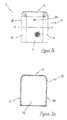
Figures 1a and 1b are exemplary front and rear elevations of a draft excluding apparatus in accordance with the invention; -
Figures 2a and 2b are exemplary plan and underside views of the draft excluding apparatus ofFigures 1 a and 1 b; -
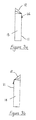
Figures 3a and 3b are exemplary side elevations of the draft excluding apparatus ofFigures 1 a and 1 b; and -
Figure 4 is an exemplary cross sectional illustration of a draft excluding apparatus in accordance with the invention - Referring initially to
Figure 1 there is shown a freestandingdraught excluding apparatus 1 adapted to seal a fireplace, the apparatus comprising abarrier member 10 formed generally havingfront 11,top 12 andside faces top 12 and side faces 13, 14 project rearwardly from thefront face 11 to define aninterior space 15 on the reverse side of barrier member (Figure 2b ). Draught excludingapparatus 1 also includes arim 16 which extends around the periphery of said barrier member. Alifting handle 26 is also provided. - Conveniently, the
barrier member 10 has a depth defined by the lengths oftop 12 andside faces front face 10. In this way the lower, i.e. ground engaging, edges of the respective side faces 12, 13 of thebarrier member 10 function as leg members which enable the draught excluding apparatus to support itself in an upright orientation. - With reference to
Figure 4 , which shows a cross-section through X-X as indicated inFigure 1a , theinterior space 15 defined on the reverse side ofbarrier 10 is provided with one or more layers ofinsulating material 20 which extends substantially across said interior space, and a layer of fireretardant material 22 which extends over and covers the one or more layers ofinsulating material 20. Preferably, the insulating material comprises fibreglass wool. Preferably the layer of fireretardant material 22 is in the form of, or comprises, a fire blanket. - As shown in
Figure 4 ,rim 16 is provided with a resilient sealing means 30 which extends around said rim and which is adapted to abut a fireplace surround and/or hearth (not shown) in use to form a seal. Resilient sealing means 30 may be a continuous strip, or formed from a number of separate strips arranged end to end to form a gasket, or a portion of a gasket. The resilient sealing means 30 is made from a suitable flexible fireproof material. Ideally, the resilient sealing means 30 is in the form of or comprises a fireproof draught strip or strips. - It will be appreciated that the resilient sealing means may be absent from the portion of the rim along the lower in use edge of the
barrier member 10. - In one embodiment, the
barrier member 10 is formed from wire mesh, as shown by way of example inFigure 1a . This provides a particularly light weight and easily movable apparatus. - In an alternative embodiment (not shown), the barrier member is formed from sheet metal.
- In each case, the front 11,
side - Where the
barrier member 10 is formed from wire mesh, therim 16 comprises a substantially rigid frame to which thebarrier member 10 is attached. - In the embodiment where the
barrier member 10 is formed from sheet metal, the rim may be defined by the terminal edges of the front and/or top and side faces of said barrier member. - The one or more layers of insulating
material 20 may be enclosed or covered with sheets or layers ofpolymer material 24 arranged on one or each side of said insulating material. InFigure 4 , a layer ofpolymer material 24 is shown located immediately behind thebarrier member 11. In this way, layer ofpolymer material 24 is located between thebarrier member 11 and the insulatingmaterial 20. In this way, the insulatinglayer 20 and/or layers is/are concealed from view where thebarrier member 10 is formed from wire mesh. The layer ofpolymer material 24 between thebarrier member 11 and the insulatingmaterial 20 can be coloured with same colour as the wire mesh. - With reference to
Figure 4 , the respective terminal edges layers ofpolymer material 24 and the layer offire retardant material 22 are fastened to therim 16 of the draught excluding apparatus. Optionally, the layer(s) ofpolymer material 24 and the layer offire retardant material 22 may be joined together at their respective terminal edges to form a unitary assembly. - In use, the
draught excluding apparatus 1 is placed around the fire box opening of a fireplace such that the resilient sealingmember 30 abuts the fireplace surround and/or hearth such that a substantially airtight seal is formed around said fire box opening without the need for mechanical fastening of the draught excluding apparatus to the fireplace. Furthermore, the draught excluding apparatus can be placed away from the fire box opening and stood upright without the need for particular storage. - The presence of an insulating
material 20 which extends substantially over the interior space defined on the reverse side of the barrier member mitigates the loss of thermal energy through thedraught excluding apparatus 10 by means conduction and/or convection. Similarly, the insulatingmaterial 20 mitigates cold bridging across thedraught excluding apparatus 10. In this way, the draft excluding apparatus conserves heat energy in the room where it is located in use. The insulatingmaterial 20 also serves to prevent thebarrier member 10 ofdraught excluding apparatus 10 from becoming excessively hot in use. - In addition, a draft excluding apparatus in accordance with the embodiments of the invention can be made to fit any size of fireplace or fire box.
Claims (15)
- A freestanding draught excluding apparatus adapted to close the opening of an open fireplace seal a fireplace, the apparatus comprising:a barrier member formed generally having front, top and side faces, wherein the top and side faces project rearwardly from the front face to define an interior space on the reverse side of barrier member;a rim which extends around the periphery of said barrier member;wherein the interior space defined on the reverse side of the barrier member is provided with one or more layers of insulating material which extends substantially across said interior space within the barrier member;a layer of fire retardant material which extends over and covers the one or more layers of insulating material; andwherein the rim is provided with a resilient sealing means which extends substantially around said rim and which is adapted to abut a fireplace surround and/or hearth in use to form a substantially airtight seal.
- A draught excluding apparatus as claimed in claim 1, wherein the draught excluding apparatus further comprises a lifting handle.
- A draught excluding apparatus as claimed in claim 1 or claim 2, wherein the barrier member is formed from wire mesh.
- A draught excluding apparatus as claimed in claim 1 or claim 2, wherein the barrier member is formed from sheet metal.
- A draught excluding apparatus as claimed in claim 3, wherein the rim comprises a substantially rigid frame to which the barrier member is attached.
- A draught excluding apparatus as claimed in claim 4, wherein the rim is defined by the terminal edges of the front, top and side faces of the barrier member.
- A draught excluding apparatus as claimed in any preceding claim, wherein there is provided a layer of polymer material between the barrier member and the one or more layers of insulating material.
- A draught excluding apparatus as claimed in any one of claims 1 to 6, wherein the one or more layers of insulating material is/are enclosed between layers of polymer material arranged on each side of said one or more layers of insulating material.
- A draught excluding apparatus as claimed in any preceding claim, wherein the insulating material comprises fibreglass wool.
- A draught excluding apparatus as claimed in any preceding claim, wherein the insulating material comprises fibreglass wool.
- A draught excluding apparatus as claimed in any preceding claim, wherein the fire retardant layer is in the form of or comprises a fire blanket.
- A draught excluding apparatus as claimed in any preceding claim, wherein the resilient sealing means comprises a fireproof draught strip.
- A draught excluding apparatus as claimed in any preceding claim, wherein the respective terminal edges of the layers of polymer material and the layer of fire retardant material are mechanically fastened to the rim of said draught excluding apparatus.
- A draught excluding apparatus as claimed in in any preceding claim, wherein the barrier member is formed from a single piece of material.
- A draught excluding apparatus as claimed in claim 3 or claim 4, wherein the barrier member is formed from a plurality of interconnected sections of material.
Priority Applications (1)
| Application Number | Priority Date | Filing Date | Title |
|---|---|---|---|
| EP15192829.8A EP3165827A1 (en) | 2015-11-03 | 2015-11-03 | Draft exclusion apparatus |
Applications Claiming Priority (1)
| Application Number | Priority Date | Filing Date | Title |
|---|---|---|---|
| EP15192829.8A EP3165827A1 (en) | 2015-11-03 | 2015-11-03 | Draft exclusion apparatus |
Publications (1)
| Publication Number | Publication Date |
|---|---|
| EP3165827A1 true EP3165827A1 (en) | 2017-05-10 |
Family
ID=54476766
Family Applications (1)
| Application Number | Title | Priority Date | Filing Date |
|---|---|---|---|
| EP15192829.8A Withdrawn EP3165827A1 (en) | 2015-11-03 | 2015-11-03 | Draft exclusion apparatus |
Country Status (1)
| Country | Link |
|---|---|
| EP (1) | EP3165827A1 (en) |
Citations (4)
| Publication number | Priority date | Publication date | Assignee | Title |
|---|---|---|---|---|
| US3378003A (en) * | 1966-05-03 | 1968-04-16 | Scherer Wallace Earl | Fireplace screen |
| US4010730A (en) * | 1975-06-11 | 1977-03-08 | Mitchell Terry L | Fireplace shield |
| CA2459747A1 (en) * | 1999-02-15 | 2000-08-15 | Fpi Fireplace Products International Ltd. | Fireplace screen assembly |
| US6748943B1 (en) * | 2003-05-01 | 2004-06-15 | John P. Krimmer | Fireplace cover |
-
2015
- 2015-11-03 EP EP15192829.8A patent/EP3165827A1/en not_active Withdrawn
Patent Citations (4)
| Publication number | Priority date | Publication date | Assignee | Title |
|---|---|---|---|---|
| US3378003A (en) * | 1966-05-03 | 1968-04-16 | Scherer Wallace Earl | Fireplace screen |
| US4010730A (en) * | 1975-06-11 | 1977-03-08 | Mitchell Terry L | Fireplace shield |
| CA2459747A1 (en) * | 1999-02-15 | 2000-08-15 | Fpi Fireplace Products International Ltd. | Fireplace screen assembly |
| US6748943B1 (en) * | 2003-05-01 | 2004-06-15 | John P. Krimmer | Fireplace cover |
Similar Documents
| Publication | Publication Date | Title |
|---|---|---|
| EP1521617B1 (en) | Fireblocking device | |
| JP6240546B2 (en) | Ventilator for sash window and sash window | |
| MY159003A (en) | Ember-resistant and flame-resistant roof ventilation system | |
| US3789825A (en) | Fireplace closure apparatus | |
| CN105888455A (en) | Fireproof door with automatic ventilation function | |
| CN205743563U (en) | Can the new structure fire resistant doorsets of ventilated type | |
| US4102321A (en) | Fireplace screen | |
| HRP20140999T1 (en) | FLAT-RESISTANT FLAT CLOSE | |
| US10739014B2 (en) | System and method to cool an exposed surface of an appliance | |
| JP2010121311A (en) | Side visor for window of building | |
| JP5283416B2 (en) | Cover plate for eave sky ventilation bracket, eave sky ventilation bracket structure, and eave sky ventilation structure | |
| Roulet et al. | Specific devices for natural ventilation | |
| JP2006071264A (en) | Building ventilation equipment | |
| KR101179282B1 (en) | Ventilation Window Frame | |
| KR200340845Y1 (en) | The anti-insects mesh sunvisor | |
| JP2015193981A (en) | Sash window | |
| JP2000314186A (en) | Eaves unit | |
| JP7542394B2 (en) | Fittings | |
| JP3789010B2 (en) | Fire prevention ventilation structure of the building | |
| CN213572562U (en) | Double-layer curtain wall system | |
| KR20180002298U (en) | A window for ventilation | |
| CN209780677U (en) | Fireproof mounting structure of fireproof window | |
| JP4165327B2 (en) | Airflow window | |
| CN2906004Y (en) | Ventilation lighting window | |
| CN104213699A (en) | Water-proof exhaust port |
Legal Events
| Date | Code | Title | Description |
|---|---|---|---|
| PUAI | Public reference made under article 153(3) epc to a published international application that has entered the european phase |
Free format text: ORIGINAL CODE: 0009012 |
|
| STAA | Information on the status of an ep patent application or granted ep patent |
Free format text: STATUS: THE APPLICATION HAS BEEN PUBLISHED |
|
| AK | Designated contracting states |
Kind code of ref document: A1 Designated state(s): AL AT BE BG CH CY CZ DE DK EE ES FI FR GB GR HR HU IE IS IT LI LT LU LV MC MK MT NL NO PL PT RO RS SE SI SK SM TR |
|
| AX | Request for extension of the european patent |
Extension state: BA ME |
|
| STAA | Information on the status of an ep patent application or granted ep patent |
Free format text: STATUS: THE APPLICATION IS DEEMED TO BE WITHDRAWN |
|
| 18D | Application deemed to be withdrawn |
Effective date: 20171111 |