EP3165725A1 - Control device of engine - Google Patents
Control device of engine Download PDFInfo
- Publication number
- EP3165725A1 EP3165725A1 EP16196381.4A EP16196381A EP3165725A1 EP 3165725 A1 EP3165725 A1 EP 3165725A1 EP 16196381 A EP16196381 A EP 16196381A EP 3165725 A1 EP3165725 A1 EP 3165725A1
- Authority
- EP
- European Patent Office
- Prior art keywords
- ignition
- index
- lubricating oil
- low speed
- speed pre
- Prior art date
- Legal status (The legal status is an assumption and is not a legal conclusion. Google has not performed a legal analysis and makes no representation as to the accuracy of the status listed.)
- Granted
Links
Images


Classifications
-
- F—MECHANICAL ENGINEERING; LIGHTING; HEATING; WEAPONS; BLASTING
- F01—MACHINES OR ENGINES IN GENERAL; ENGINE PLANTS IN GENERAL; STEAM ENGINES
- F01M—LUBRICATING OF MACHINES OR ENGINES IN GENERAL; LUBRICATING INTERNAL COMBUSTION ENGINES; CRANKCASE VENTILATING
- F01M1/00—Pressure lubrication
- F01M1/16—Controlling lubricant pressure or quantity
-
- F—MECHANICAL ENGINEERING; LIGHTING; HEATING; WEAPONS; BLASTING
- F01—MACHINES OR ENGINES IN GENERAL; ENGINE PLANTS IN GENERAL; STEAM ENGINES
- F01M—LUBRICATING OF MACHINES OR ENGINES IN GENERAL; LUBRICATING INTERNAL COMBUSTION ENGINES; CRANKCASE VENTILATING
- F01M1/00—Pressure lubrication
- F01M1/08—Lubricating systems characterised by the provision therein of lubricant jetting means
-
- F—MECHANICAL ENGINEERING; LIGHTING; HEATING; WEAPONS; BLASTING
- F02—COMBUSTION ENGINES; HOT-GAS OR COMBUSTION-PRODUCT ENGINE PLANTS
- F02D—CONTROLLING COMBUSTION ENGINES
- F02D35/00—Controlling engines, dependent on conditions exterior or interior to engines, not otherwise provided for
- F02D35/02—Controlling engines, dependent on conditions exterior or interior to engines, not otherwise provided for on interior conditions
- F02D35/028—Controlling engines, dependent on conditions exterior or interior to engines, not otherwise provided for on interior conditions by determining the combustion timing or phasing
-
- F—MECHANICAL ENGINEERING; LIGHTING; HEATING; WEAPONS; BLASTING
- F01—MACHINES OR ENGINES IN GENERAL; ENGINE PLANTS IN GENERAL; STEAM ENGINES
- F01M—LUBRICATING OF MACHINES OR ENGINES IN GENERAL; LUBRICATING INTERNAL COMBUSTION ENGINES; CRANKCASE VENTILATING
- F01M2250/00—Measuring
- F01M2250/60—Operating parameters
-
- F—MECHANICAL ENGINEERING; LIGHTING; HEATING; WEAPONS; BLASTING
- F01—MACHINES OR ENGINES IN GENERAL; ENGINE PLANTS IN GENERAL; STEAM ENGINES
- F01M—LUBRICATING OF MACHINES OR ENGINES IN GENERAL; LUBRICATING INTERNAL COMBUSTION ENGINES; CRANKCASE VENTILATING
- F01M2250/00—Measuring
- F01M2250/62—Load
Definitions
- the present invention relates to a control device of an engine which is provided with an exhaust gas recirculation device, and more particularly, to the control device of the engine for preventing occurrence of low speed pre-ignition which occurs, while the engine is operated at low speed rotation and a high load.
- an engine which is mounted on a vehicle or the like is provided with an exhaust gas recirculation device.
- the exhaust gas recirculation device recirculates a part of an exhaust gas which is exhausted from a combustion chamber of the engine to the atmosphere through an exhaust passage, into an intake passage, thereby to lower combustion temperature inside the combustion chamber, and to restrain exhaustion of nitrogen oxide (NOx) which is contained in the exhaust gas.
- NOx nitrogen oxide
- an exhaust port of the recirculated gas to the intake passage is disposed near the combustion chamber, and a direction of the exhaust port is so set that the recirculated gas which is introduced into the combustion chamber flows along an inner peripheral wall of a cylinder.
- the recirculated gas which is swirled along the inner peripheral wall of the cylinder inside the combustion chamber forms an annular layer of the recirculated gas in a region near the inner peripheral wall.
- concentration of the exhaust gas is relatively lowered thereby to enhance ignition performance
- concentration of the exhaust gas near the inner peripheral wall of the cylinder is enhanced thereby to restrain a phenomenon of self ignition of an end gas, that is, so-called knocking.
- JP-A-2010-84619 there is disclosed a technique for predicting a self ignition phenomenon which is called as low speed pre-ignition.
- a cause for occurrence of ordinary pre-ignition is, for example, a deposit which is accumulated inside the combustion chamber. After this deposit is peeled off from a wall face of the cylinder, the deposit is exposed to burning, and red heated, resulting in a source of the self ignition.
- a cause for occurrence of the low speed pre-ignition besides the above described deposit is considered to be drops of lubricating oil which are splashed, for example, from the inner peripheral wall of the cylinder. The drops of the lubricating oil are fired with a rise of the temperature inside the combustion chamber, and become a fire source for the self ignition of a gas mixture.
- a control device of an engine including: a piston which is contained in a cylinder; an intake passage which is communicated to a combustion chamber of the cylinder; an exhaust passage which is led from the combustion chamber; a fuel injection valve which is configured to inject fuel to the combustion chamber or the intake passage; and an ignition unit which is provided in the combustion chamber
- the control device comprising: a low speed pre-ignition predicting unit which is configured to perform prediction of occurrence of low speed pre-ignition, based on operation condition of the engine; and a lubricating oil injection controlling unit which is configured to control a lubricating oil injecting device to inject lubricating oil to the piston or a member located around the piston, based on the prediction of the occurrence of the low speed pre-ignition performed by the low speed pre-ignition predicting unit.
- FIG. 1 is a schematic view showing structure of an engine E and a control device of the engine E in this invention.
- the engine E in this embodiment is a four-cycle gasoline engine provided with a supercharger, for an automobile.
- a piston 2 is contained in a cylinder 1 of the engine.
- a combustion chamber 3 is defined by an inner face of the cylinder 1 and an upper face of the piston 2 and so on.
- the engine E is provided with an intake passage 4 for feeding an intake air into the combustion chamber 3 which contains the piston 2, an exhaust passage 5 which is led from the combustion chamber 3, a fuel injection valve 13 for injecting fuel into the combustion chamber 3, and so on.
- an ignition plug as an ignition unit 12 is provided in a downward direction along an axis of the cylinder from a cylinder head side.
- An intake valve port which is an opening between the intake passage 4 and the combustion chamber 3 is opened or closed by an intake valve 6.
- an exhaust valve port which is an opening between the exhaust passage 5 and the combustion chamber 3 is opened or closed by an exhaust valve 7.
- the exhaust passage 5 and the intake passage 4 are communicated to each other by a recirculated gas passage 11 which forms an exhaust gas recirculation device 10.
- the exhaust gas recirculation device 10 has a function of recirculating a part of the exhaust gas which is exhausted from the engine, as the recirculated gas, from the exhaust passage 5 upstream than a turbine of a turbo charger 16 to the intake passage 4 downstream than a compressor of the turbo charger 16.
- the exhaust gas recirculation device 10 is not limited to the above described, but a part of the exhaust gas which is exhausted from the engine may be recirculated as the recirculated gas, from the exhaust passage 5 downstream than the turbine of the turbo charger 16 to the intake passage 4 upstream than the compressor of the turbo charger 16.
- the recirculated gas passage 11 is provided with a recirculated gas controlling unit 11a capable of adjusting an amount of the gas which flows by opening or closing the passage.
- the fuel injection valve 13 is so arranged that the fuel injected from the fuel injection valve 13 is directed to a top face of the piston 2, while the piston 2 contained in the combustion chamber 3 is positioned close to an upper dead center, and directed to a wall face of the combustion chamber 3, while the piston 2 is positioned close to a lower dead center.
- the electronic control unit 20 is provided with a low speed pre-ignition predicting unit 23 for predicting occurrence of the low speed pre-ignition on the basis of running condition of the engine.
- the engine E is provided with a lubricating oil injecting device 15 for injecting the lubricating oil to the piston 2 or a member located around the piston 2.
- the lubricating oil injecting device 15 includes an injection nozzle 15a for the lubricating oil which is provided in a crank case below the piston 2 so as to be directed to a lower face of the piston 2, and a control valve 15b for opening or closing a feeding passage of the lubricating oil to the injection nozzle 15a.
- the lubricating oil which is injected from the injection nozzle 15a is blown to the lower face of the piston 2, that is, the face of the piston 2 at an opposite side to the combustion chamber 3, a connecting rod which is connected thereto, an inner wall of the cylinder, and so on.
- the injection nozzle 15a is so constructed that an injecting direction of the lubricating oil can be changed by an actuating device such as a motor, and an injecting angle can be also increased or decreased. Therefore, it is possible to selectively inject the lubricating oil to an outer peripheral part, a center part or an entire surface of the lower face of the piston 2.
- the electronic control unit 20 is provided with a lubricating oil injection controlling unit 25 which commands the lubricating oil injecting device 15 to inject the lubricating oil, on the basis of the prediction of occurrence of the low speed pre-ignition which is made by the low speed pre-ignition predicting unit 23.
- the lubricating oil injection controlling unit 25 controls opening or closing of the control valve 15b.
- the electronic control unit 20 is provided with a self ignition index calculating unit 21 for calculating a self ignition index K0 which indicates possibility of occurrence of the self ignition of the fuel at a crank angle before an ignition time during a compression stroke, on the basis of the temperature and pressure inside the combustion chamber 3.
- the crank angle CA before the ignition time which is an end time of an integral range in the predicting equation, is considered to be set at an end time of the range in which there is possibility of occurrence of the low speed pre-ignition, that is, at the crank angle just before the ignition time.
- the self ignition index calculating unit 21 may use other predicting equations in which at least the temperature and the pressure inside the combustion chamber 3 are taken as calculating elements.
- the electronic control unit 20 is provided with a first correction coefficient calculating unit 22 for calculating a wall face adhered fuel correction coefficient C1 for correcting the self ignition index, on the basis of an amount of the fuel which is adhered to the wall face inside the combustion chamber 3 at the crank angle before the ignition time during the compression stroke.
- the first corrected self ignition index K1 is equal to or higher than a predetermined value, it is predicted that the low speed pre-ignition occurs up to a predetermined ignition time during the compression stroke (that is, up to the crank angle CA before the ignition time which is set by the predicting equation. Hereinafter, the same is applied). In case where the first corrected self ignition index K1 is lower than the predetermined value, it is predicted that the low speed pre-ignition will not occur before the ignition time during the compression stroke. It is to be noted that the prediction of the low speed pre-ignition based on the first corrected self ignition index K1 may be omitted, in case where occurrence of the low speed pre-ignition is predicted on the basis of a second corrected self ignition index K2, which will be described below.
- P(the pressure at the respective crank angles) and T(the temperature at the respective crank angles) can be calculated by a condition equation, on the basis of the amount of the intake air into the combustion chamber 3, and IC (temperature and pressure inside the cylinder at a closing time of the intake valve), for example.
- the amount of the adhered fuel which is a base for calculating the wall face adhered fuel correction coefficient C1 can be estimated from a fuel injection time (indicated by a crank angle before the upper dead center of the compression) on an X-axis, and temperature of a cooling medium of the engine (temperature of cooling water of the engine) on a Y-axis, as shown in a map view in Fig. 3A .
- the proper wall face adhered fuel correction coefficient C1 is set with respect to every amount of the adhered fuel a to n which has been estimated.
- this map view in Fig. 3A is made with respect to a specified intake temperature, map views with respect to other intake temperatures are separately set.
- An interval between the intake temperatures for setting the map view can be freely selected, for example, at every 1°C, at every 5°C, and so on.
- the wall face adhered fuel correction coefficient C1 for correcting the self ignition index K0, on the basis of the amount of the adhered fuel a to k. It is to be noted that the wall face adhered fuel correction coefficient C1 takes a value 1 in case where there is no adhesion of the fuel, and therefore, takes a value larger than 1 in case where there is adhesion of the fuel.
- an intake oxygen concentration correction coefficient C2 is adopted.
- the electronic control unit 20 is provided with a second correction coefficient calculating unit 24 for calculating the intake oxygen concentration correction coefficient C2 for correcting the first corrected self ignition index K1, on the basis of a ratio of the recirculated gas in the intake air into the combustion chamber 3.
- the intake oxygen concentration correction coefficient C2 can be calculated to be a to z , for example, as shown in a map view in Fig. 3C , on the basis of ratio of the recirculated gas in the intake air into the combustion chamber 3. It is to be noted that the intake oxygen concentration correction coefficient C2 takes a value 1, in case where the recirculated gas is not contained in the intake air, and takes a value smaller than 1 and larger than 0, because the value becomes smaller as a larger amount of the recirculated gas is contained in the intake air.
- the second corrected self ignition index K2 is larger than the predetermined value, it is predicted that the low speed pre-ignition will occur, before the predetermined ignition time during the compression stroke. In case where the second corrected self ignition index K2 is smaller than the predetermined value, it is predicted that the low speed pre-ignition will not occur, before the predetermined ignition time during the compression stroke.
- the above described predetermined value for the first corrected self ignition index K1 and the predetermined value for the second corrected self ignition index K2 may be the same value. However, these predetermined values may be different from each other.
- the predetermined value for the third corrected self ignition index K3 may be the same value as those predetermined values or may be a different value from them. In case where those predetermined values are different from each other, the third corrected self ignition index K3 may be the same value as either of those predetermined values, or may be a different value from any of those predetermined values.
- a control for injecting a lubricating oil to the piston 2 and the member located around the piston in the cylinder is conducted, for the purpose of avoiding occurrence of the low speed pre-ignition.
- the temperature inside the combustion chamber 3 is lowered with the injection of the lubricating oil, and accordingly, occurrence of the low speed pre-ignition is depressed.
- This control for injecting the lubricating oil is carried out by the lubricating oil injection controlling unit 25.
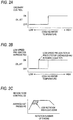
- Fig. 2A is a graph showing the control for injecting the lubricating oil for the purpose of restraining knocking or the ordinary pre-ignition, based on temperature of the cooling water of the engine E.
- Fig. 2B shows that although the temperature of the cooling water does not reach the predetermined temperature, the injection of the lubricating oil is started, because occurrence of the low speed pre-ignition is predicted. Injecting direction of the lubricating oil can be optionally selected.
- the lubricating oil may be mainly injected from the injection nozzle 15a to a center part of the lower face of the piston 2 or an entirety of the lower face of the piston 2, in case of the injection control of the lubricating oil based on the temperature of the cooling water of the engine E, as shown in Fig. 2A .
- the lubricating oil may be mainly injected from the injection nozzle 15a to an outer peripheral part of the lower face of the piston 2.
- the injecting direction of the lubricating oil on the basis of the indexes such as the first corrected self ignition index K1, the second corrected self ignition index K2, and the third corrected self ignition index K3, may be different from the injecting direction of the lubricating oil on occasion of injecting on the basis of other control indexes such as the temperature of the cooling water.
- occurrence of the low speed pre-ignition can be possibly predicted in a low rotation high load zone, as shown in Fig. 2C . In this low rotation high load zone, even under such operation condition that the lubricating oil is not injected under the ordinary control, the lubricating oil is injected, because occurrence of the low speed pre-ignition is predicted.
- the third corrected self ignition index K3 is larger than the relevant predetermined value.
- the wall face adhered fuel correction coefficient C1 takes a value larger than 1
- the intake oxygen concentration correction coefficient C2 takes a value smaller than 1 and larger than 0. Therefore, in case where the third corrected self ignition index K3 is larger than the relevant predetermined value, it is considered that estimation by the first corrected self ignition index K1 and estimation by the second corrected self ignition index K2 are also larger than the relevant predetermined values, in case where the predetermined values for the indexes K1, K2, K3 are set to be the same value.
- the predetermined values for the indexes K1, K2, K3 are set to be the same value.
- the respective indexes K1, K2 are larger than the relevant predetermined values, in many cases. For this reason, it is necessary to carry out control for avoiding the low speed pre-ignition in an early period. Therefore, in this example, the amount of the lubricating oil is set to be relatively larger than the above described injection control in Example 1.
- the first corrected self ignition index K1 will be described, as an example.
- Estimated values for the first corrected self ignition index K1 are determined by a plurality of steps. These values are named as a first estimated value t1, a second estimated value t2, and a third estimated value t3 in order from the smallest value.
- the amount of the lubricating oil to be injected may be different, depending on whether or not the value of the index K1 is larger than the predetermined value and smaller than the first estimated value t1, whether or not the value is larger than the first estimated value t1 and smaller than the second estimated value t2, whether or not the value is larger than the second estimated value t2 and smaller than the third estimated value t3, and whether or not the value is larger than the third estimated value t3. Because there is a larger possibility of occurrence of the low speed pre-ignition, as the value of the first corrected self ignition index K1 grows larger, the amount of the lubricating oil to be injected is also increased.
- the amount of the lubricating oil which is injected by the lubricating oil injecting device 15 may be increased stepwise, as the value of the index grows larger, on the basis of either of the first corrected self ignition index K1, the second corrected self ignition index K2, and the third corrected self ignition index K3.
- it may be so constructed that the value of either of the indexes K1, K2, K3 and the amount of the lubricating oil are matched with each other in ratio of 1 to 1, using the map or the like, and then, the amount of the lubricating oil is increased, as the value of the index K1, K2, K3 grows larger.
- a cylinder inside injection valve (a direct injection valve) for directly injecting the fuel into the combustion chamber 3 is adopted as the fuel injection valve 13, it is also possible to substitute this valve with a port injection valve for injecting the fuel into the intake passage 4.
- the cylinder inside injection valve and the port injection valve may be combined for use, as the fuel injection valve 13.
- the lubricating oil is injected to the piston or the member located around the piston, based on information concerning prediction of occurrence of the low speed pre-ignition. As the results, it is possible to more reliably prevent occurrence of the pre-ignition inside the combustion chamber.
Landscapes
- Engineering & Computer Science (AREA)
- Mechanical Engineering (AREA)
- General Engineering & Computer Science (AREA)
- Chemical & Material Sciences (AREA)
- Combustion & Propulsion (AREA)
- Electrical Control Of Air Or Fuel Supplied To Internal-Combustion Engine (AREA)
- Lubrication Of Internal Combustion Engines (AREA)
- Combined Controls Of Internal Combustion Engines (AREA)
Abstract
Description
- The present invention relates to a control device of an engine which is provided with an exhaust gas recirculation device, and more particularly, to the control device of the engine for preventing occurrence of low speed pre-ignition which occurs, while the engine is operated at low speed rotation and a high load.
- In many cases, an engine which is mounted on a vehicle or the like is provided with an exhaust gas recirculation device. The exhaust gas recirculation device recirculates a part of an exhaust gas which is exhausted from a combustion chamber of the engine to the atmosphere through an exhaust passage, into an intake passage, thereby to lower combustion temperature inside the combustion chamber, and to restrain exhaustion of nitrogen oxide (NOx) which is contained in the exhaust gas.
- Moreover, there has been a technique for reducing abnormal combustion inside the combustion chamber of the engine, using the exhaust gas which is recirculated to the intake passage (hereinafter referred to as "recirculated gas") by the exhaust gas recirculation device.
- For example, in
JP-A-S62-131961 - Moreover, in
JP-A-2010-84619 - As measures for preventing the ordinary pre-ignition, there is a method of delaying an ignition time. On the other hand, as measures for preventing the low speed pre-ignition, there is a method of lowering temperature of an intake air, and a method of lowering concentration of oxygen in the gas mixture, for example. However, in case where the method of lowering the temperature of the intake air is adopted, remarkable reduction of output power is incurred, depending on condition of operation, in some cases. Moreover, in case where an amount of the recirculated gas which is introduced into the intake air is increased for the purpose of lowering the concentration of oxygen in the gas mixture, for example, in
Patent Document 1, the pre-ignition is induced to the contrary, in some cases. For this reason, there is a limit in increasing the amount of the recirculated gas. - In view of the above, it is an object of the present invention to more reliably prevent occurrence of low speed pre-ignition inside a combustion chamber.
- In order to solve the above described problem, according to the invention, there is provided a control device of an engine, the engine including: a piston which is contained in a cylinder; an intake passage which is communicated to a combustion chamber of the cylinder; an exhaust passage which is led from the combustion chamber; a fuel injection valve which is configured to inject fuel to the combustion chamber or the intake passage; and an ignition unit which is provided in the combustion chamber, the control device comprising: a low speed pre-ignition predicting unit which is configured to perform prediction of occurrence of low speed pre-ignition, based on operation condition of the engine; and a lubricating oil injection controlling unit which is configured to control a lubricating oil injecting device to inject lubricating oil to the piston or a member located around the piston, based on the prediction of the occurrence of the low speed pre-ignition performed by the low speed pre-ignition predicting unit.
-
-
Fig. 1 is a schematic view of a control device of an engine in an embodiment according to this invention. -
Figs. 2A to 2C are graphs which are used in controls according to this invention. -
Figs. 3A to 3C are map views which are used in the controls according to this invention. - An embodiment according to this invention will be described referring to the drawings.
Fig. 1 is a schematic view showing structure of an engine E and a control device of the engine E in this invention. - The engine E in this embodiment is a four-cycle gasoline engine provided with a supercharger, for an automobile. A
piston 2 is contained in acylinder 1 of the engine. Acombustion chamber 3 is defined by an inner face of thecylinder 1 and an upper face of thepiston 2 and so on. - The engine E is provided with an
intake passage 4 for feeding an intake air into thecombustion chamber 3 which contains thepiston 2, anexhaust passage 5 which is led from thecombustion chamber 3, afuel injection valve 13 for injecting fuel into thecombustion chamber 3, and so on. Moreover, an ignition plug as anignition unit 12 is provided in a downward direction along an axis of the cylinder from a cylinder head side. - In these drawings, those members and means which are directly related to the invention are mainly shown, and other members are omitted in the drawings. Moreover, although only one cylinder is shown in the drawings, the number of the cylinders in the engine E is not limited.
- An intake valve port which is an opening between the
intake passage 4 and thecombustion chamber 3 is opened or closed by anintake valve 6. Moreover, an exhaust valve port which is an opening between theexhaust passage 5 and thecombustion chamber 3 is opened or closed by anexhaust valve 7. - These
intake valve 6,exhaust valve 7,ignition unit 12,fuel injection valve 13, and other equipments which are required for operating the engine are respectively controlled by a control unit which is provided in anelectronic control unit 20, by way of cables. - Moreover, the
exhaust passage 5 and theintake passage 4 are communicated to each other by a recirculatedgas passage 11 which forms an exhaustgas recirculation device 10. The exhaustgas recirculation device 10 has a function of recirculating a part of the exhaust gas which is exhausted from the engine, as the recirculated gas, from theexhaust passage 5 upstream than a turbine of aturbo charger 16 to theintake passage 4 downstream than a compressor of theturbo charger 16. It is to be noted that the exhaustgas recirculation device 10 is not limited to the above described, but a part of the exhaust gas which is exhausted from the engine may be recirculated as the recirculated gas, from theexhaust passage 5 downstream than the turbine of theturbo charger 16 to theintake passage 4 upstream than the compressor of theturbo charger 16. - The recirculated
gas passage 11 is provided with a recirculatedgas controlling unit 11a capable of adjusting an amount of the gas which flows by opening or closing the passage. - According to condition of a pressure inside the
intake passage 4 which is controlled by the recirculatedgas controlling unit 11a and athrottle valve 8 provided in theintake passage 4, and so on, a part of the exhaust gas which is exhausted from the engine E is recirculated to theintake passage 4 through the recirculatedgas passage 11, as the recirculated gas, only by a required amount. These controls are also carried out by theelectronic control unit 20 according to the operation condition. - Inside the cylinder, the
fuel injection valve 13 is so arranged that the fuel injected from thefuel injection valve 13 is directed to a top face of thepiston 2, while thepiston 2 contained in thecombustion chamber 3 is positioned close to an upper dead center, and directed to a wall face of thecombustion chamber 3, while thepiston 2 is positioned close to a lower dead center. - It is considered that as one of causes for occurrence of the pre-ignition, drops of the lubricating oil or so which are splashed from the cylindrical wall face of the
cylinder 1 are fired with a rise of the temperature inside thecombustion chamber 3, and this becomes a fire source for self ignition of the gas mixture. In view of the above, in the present invention, it is intended to predict occurrence of the low speed pre-ignition according to circumstances inside thecombustion chamber 3, and to carry out controls for avoiding such phenomenon. Further, in this invention, at a time of predicting occurrence of this low speed pre-ignition, a manner where the fuel is adhered to the wall face of thecombustion chamber 3, ratio of the recirculated gas in the intake air and so on are taken into consideration, so that more accurate prediction can be realized. - The
electronic control unit 20 is provided with a low speed pre-ignition predictingunit 23 for predicting occurrence of the low speed pre-ignition on the basis of running condition of the engine. - Moreover, the engine E is provided with a lubricating oil injecting
device 15 for injecting the lubricating oil to thepiston 2 or a member located around thepiston 2. The lubricating oil injectingdevice 15 includes aninjection nozzle 15a for the lubricating oil which is provided in a crank case below thepiston 2 so as to be directed to a lower face of thepiston 2, and acontrol valve 15b for opening or closing a feeding passage of the lubricating oil to theinjection nozzle 15a. The lubricating oil which is injected from theinjection nozzle 15a is blown to the lower face of thepiston 2, that is, the face of thepiston 2 at an opposite side to thecombustion chamber 3, a connecting rod which is connected thereto, an inner wall of the cylinder, and so on. Theinjection nozzle 15a is so constructed that an injecting direction of the lubricating oil can be changed by an actuating device such as a motor, and an injecting angle can be also increased or decreased. Therefore, it is possible to selectively inject the lubricating oil to an outer peripheral part, a center part or an entire surface of the lower face of thepiston 2. - The
electronic control unit 20 is provided with a lubricating oilinjection controlling unit 25 which commands the lubricating oil injectingdevice 15 to inject the lubricating oil, on the basis of the prediction of occurrence of the low speed pre-ignition which is made by the low speed pre-ignition predictingunit 23. The lubricating oilinjection controlling unit 25 controls opening or closing of thecontrol valve 15b. - Now, a method of predicting occurrence of the low speed pre-ignition and a method of controlling the injection of the lubricating oil, in case where the occurrence of the low speed pre-ignition is predicted will be described.
- The
electronic control unit 20 is provided with a self ignitionindex calculating unit 21 for calculating a self ignition index K0 which indicates possibility of occurrence of the self ignition of the fuel at a crank angle before an ignition time during a compression stroke, on the basis of the temperature and pressure inside thecombustion chamber 3. - The self ignition
index calculating unit 21 calculates the self ignition index K0, using a predicting equation based on Livengood-Wu integral equation,

- In this case, the self ignition
index calculating unit 21 may use other predicting equations in which at least the temperature and the pressure inside thecombustion chamber 3 are taken as calculating elements. - The
electronic control unit 20 is provided with a first correctioncoefficient calculating unit 22 for calculating a wall face adhered fuel correction coefficient C1 for correcting the self ignition index, on the basis of an amount of the fuel which is adhered to the wall face inside thecombustion chamber 3 at the crank angle before the ignition time during the compression stroke. - On the basis of a first corrected self ignition index K1 which is calculated by the above described self ignition index K0 and the wall face adhered fuel correction coefficient C1, whether or not the low speed pre-ignition occurs is predicted. This prediction is carried out by the low speed
pre-ignition predicting unit 23. - Specifically, the first corrected self ignition index K1 is as follows;

- In case where the first corrected self ignition index K1 is equal to or higher than a predetermined value, it is predicted that the low speed pre-ignition occurs up to a predetermined ignition time during the compression stroke (that is, up to the crank angle CA before the ignition time which is set by the predicting equation. Hereinafter, the same is applied). In case where the first corrected self ignition index K1 is lower than the predetermined value, it is predicted that the low speed pre-ignition will not occur before the ignition time during the compression stroke. It is to be noted that the prediction of the low speed pre-ignition based on the first corrected self ignition index K1 may be omitted, in case where occurrence of the low speed pre-ignition is predicted on the basis of a second corrected self ignition index K2, which will be described below.
- Generally, when the amount of the adhered fuel is increased, an occurring rate of the low speed pre-ignition tends to be enhanced, even in case where occurrence of the pre-ignition is not predicted at the value of the self ignition index K0. For this reason, concept of the wall face adhered fuel correction coefficient C1 for correcting the self ignition index K0 is adopted in this invention.
- Herein, P(the pressure at the respective crank angles) and T(the temperature at the respective crank angles) can be calculated by a condition equation, on the basis of the amount of the intake air into the
combustion chamber 3, and IC (temperature and pressure inside the cylinder at a closing time of the intake valve), for example. - The amount of the adhered fuel which is a base for calculating the wall face adhered fuel correction coefficient C1 can be estimated from a fuel injection time (indicated by a crank angle before the upper dead center of the compression) on an X-axis, and temperature of a cooling medium of the engine (temperature of cooling water of the engine) on a Y-axis, as shown in a map view in
Fig. 3A . The proper wall face adhered fuel correction coefficient C1 is set with respect to every amount of the adhered fuel a to n which has been estimated. Although this map view inFig. 3A is made with respect to a specified intake temperature, map views with respect to other intake temperatures are separately set. An interval between the intake temperatures for setting the map view can be freely selected, for example, at every 1°C, at every 5°C, and so on. - Alternatively, in case where the amount of the adhered fuel at the specified crank angle has been already predicted, as shown in a map view in
Fig. 3B , it is also possible to set the wall face adhered fuel correction coefficient C1 for correcting the self ignition index K0, on the basis of the amount of the adhered fuel a to k. It is to be noted that the wall face adhered fuel correction coefficient C1 takes avalue 1 in case where there is no adhesion of the fuel, and therefore, takes a value larger than 1 in case where there is adhesion of the fuel. - In case where it is desired to perform more accurate prediction of occurrence of the low speed pre-ignition, an intake oxygen concentration correction coefficient C2 is adopted.
- In case of a control device adopting the intake oxygen concentration correction coefficient C2, the
electronic control unit 20 is provided with a second correctioncoefficient calculating unit 24 for calculating the intake oxygen concentration correction coefficient C2 for correcting the first corrected self ignition index K1, on the basis of a ratio of the recirculated gas in the intake air into thecombustion chamber 3. - The intake oxygen concentration correction coefficient C2 can be calculated to be a to z, for example, as shown in a map view in
Fig. 3C , on the basis of ratio of the recirculated gas in the intake air into thecombustion chamber 3. It is to be noted that the intake oxygen concentration correction coefficient C2 takes avalue 1, in case where the recirculated gas is not contained in the intake air, and takes a value smaller than 1 and larger than 0, because the value becomes smaller as a larger amount of the recirculated gas is contained in the intake air. - Then, on the basis of a second corrected self ignition index K2 which is calculated by the first corrected self ignition index K1 and the intake oxygen concentration correction coefficient C2, whether or not the low speed pre-ignition occurs is predicted. This prediction is carried out by the low speed
pre-ignition predicting unit 23 which is provided in theelectronic control unit 20, in the same manner. The self-ignition index described in the claims, that is, the index which is calculated by the self ignition index, the wall face adhered fuel correction coefficient, and the intake oxygen concentration correction coefficient corresponds to this second corrected self ignition index K2. - Specifically, the second corrected self ignition index K2 is as follows;

- In case where the second corrected self ignition index K2 is larger than the predetermined value, it is predicted that the low speed pre-ignition will occur, before the predetermined ignition time during the compression stroke. In case where the second corrected self ignition index K2 is smaller than the predetermined value, it is predicted that the low speed pre-ignition will not occur, before the predetermined ignition time during the compression stroke.
- Generally, there is such a tendency that when ratio of the recirculated gas increases and the oxygen concentration in the intake air decreases, the gas mixture is not ignited, and occurring rate of the low speed pre-ignition is lowered. This is the reason for adopting the concept of the intake oxygen concentration correction coefficient C2 which corrects the first corrected self ignition index K1, on the basis of the ratio of the recirculated gas in the intake air introduced into the
combustion chamber 3. - In this case, the above described predetermined value for the first corrected self ignition index K1 and the predetermined value for the second corrected self ignition index K2 may be the same value. However, these predetermined values may be different from each other.
- Further, on the basis of a third corrected self ignition index K3 which is calculated by the self ignition index K0 and the intake oxygen concentration correction coefficient C2, whether or not the low speed pre-ignition occurs is predicted. This prediction is carried out by the low speed
pre-ignition predicting unit 23 which is provided in theelectronic control unit 20, in the same manner. - The third corrected self ignition index K3 is calculated by the self ignition index K0 and the intake oxygen concentration correction coefficient C2, and shown as follows;

- Herein, in case where the predetermined value for the first corrected self ignition index K1 and the predetermined value for the second corrected self ignition index K2 are the same value, the predetermined value for the third corrected self ignition index K3 may be the same value as those predetermined values or may be a different value from them. In case where those predetermined values are different from each other, the third corrected self ignition index K3 may be the same value as either of those predetermined values, or may be a different value from any of those predetermined values.
- Moreover, in this control device of the engine, in case where occurrence of the low speed pre-ignition is predicted, on the basis of estimation by the first corrected self ignition index K1, the second corrected self ignition index K2, and the third corrected self ignition index K3, a control for injecting a lubricating oil to the
piston 2 and the member located around the piston in the cylinder is conducted, for the purpose of avoiding occurrence of the low speed pre-ignition. The temperature inside thecombustion chamber 3 is lowered with the injection of the lubricating oil, and accordingly, occurrence of the low speed pre-ignition is depressed. This control for injecting the lubricating oil is carried out by the lubricating oilinjection controlling unit 25. - For example,
Fig. 2A is a graph showing the control for injecting the lubricating oil for the purpose of restraining knocking or the ordinary pre-ignition, based on temperature of the cooling water of the engine E. When the temperature of the cooling water becomes higher than a predetermined temperature, injection of the lubricating oil for cooling an inside of thecylinder 1 is started.Fig. 2B shows that although the temperature of the cooling water does not reach the predetermined temperature, the injection of the lubricating oil is started, because occurrence of the low speed pre-ignition is predicted. Injecting direction of the lubricating oil can be optionally selected. However, because it is considered that the knocking or the ordinary pre-ignition is strongly affected by high temperature of an entire inside of thecombustion chamber 3, the lubricating oil may be mainly injected from theinjection nozzle 15a to a center part of the lower face of thepiston 2 or an entirety of the lower face of thepiston 2, in case of the injection control of the lubricating oil based on the temperature of the cooling water of the engine E, as shown inFig. 2A . Moreover, because it is considered that the low speed pre-ignition is caused by firing of the lubricating oil which is splashed from the inner peripheral wall of thecombustion chamber 3, the lubricating oil may be mainly injected from theinjection nozzle 15a to an outer peripheral part of the lower face of thepiston 2. In this manner, the injecting direction of the lubricating oil on the basis of the indexes such as the first corrected self ignition index K1, the second corrected self ignition index K2, and the third corrected self ignition index K3, may be different from the injecting direction of the lubricating oil on occasion of injecting on the basis of other control indexes such as the temperature of the cooling water. It is to be noted that occurrence of the low speed pre-ignition can be possibly predicted in a low rotation high load zone, as shown inFig. 2C . In this low rotation high load zone, even under such operation condition that the lubricating oil is not injected under the ordinary control, the lubricating oil is injected, because occurrence of the low speed pre-ignition is predicted. - Concerning the above described respective indexes, the controls for injecting the lubricating oil will be described by way of some examples.
- A case where the self ignition index K0 and the third corrected self ignition index K3 are not larger than the relevant predetermined values, whereas the first corrected self ignition index K1 and the second corrected self ignition index K2 are larger than the relevant predetermined values is presumed. This is the case where the respective indexes become larger than the predetermined values, by taking the wall face adhered fuel correction coefficient C1 into consideration. Therefore, it is considered that there is less emergency of occurrence of the low speed pre-ignition in this case, and so, the injecting amount of the lubricating oil is set to be relatively smaller, as compared with other cases of the injection control.
- Then, a case where the third corrected self ignition index K3 is larger than the relevant predetermined value is presumed. The wall face adhered fuel correction coefficient C1 takes a value larger than 1, whereas the intake oxygen concentration correction coefficient C2 takes a value smaller than 1 and larger than 0. Therefore, in case where the third corrected self ignition index K3 is larger than the relevant predetermined value, it is considered that estimation by the first corrected self ignition index K1 and estimation by the second corrected self ignition index K2 are also larger than the relevant predetermined values, in case where the predetermined values for the indexes K1, K2, K3 are set to be the same value. Alternatively, it is considered that even though the predetermined values are set to be different from each other, the respective indexes K1, K2 are larger than the relevant predetermined values, in many cases. For this reason, it is necessary to carry out control for avoiding the low speed pre-ignition in an early period. Therefore, in this example, the amount of the lubricating oil is set to be relatively larger than the above described injection control in Example 1.
- On the basis of the values of the first corrected self ignition index K1, the second corrected self ignition index K2, and the third corrected self ignition index K3 as described above, it is possible to carry out the control for increasing or decreasing the amount of the lubricating oil which is injected by the lubricating
oil injecting device 15. - For example, the first corrected self ignition index K1 will be described, as an example. Estimated values for the first corrected self ignition index K1 are determined by a plurality of steps. These values are named as a first estimated value t1, a second estimated value t2, and a third estimated value t3 in order from the smallest value. In case where the value of the first corrected self ignition index K1 exceeds the predetermined value which is a standard for predicting occurrence of the low speed pre-ignition, it is so set that the amount of the lubricating oil to be injected may be different, depending on whether or not the value of the index K1 is larger than the predetermined value and smaller than the first estimated value t1, whether or not the value is larger than the first estimated value t1 and smaller than the second estimated value t2, whether or not the value is larger than the second estimated value t2 and smaller than the third estimated value t3, and whether or not the value is larger than the third estimated value t3. Because there is a larger possibility of occurrence of the low speed pre-ignition, as the value of the first corrected self ignition index K1 grows larger, the amount of the lubricating oil to be injected is also increased.
- In this manner, the amount of the lubricating oil which is injected by the lubricating
oil injecting device 15 may be increased stepwise, as the value of the index grows larger, on the basis of either of the first corrected self ignition index K1, the second corrected self ignition index K2, and the third corrected self ignition index K3. Alternatively, it may be so constructed that the value of either of the indexes K1, K2, K3 and the amount of the lubricating oil are matched with each other in ratio of 1 to 1, using the map or the like, and then, the amount of the lubricating oil is increased, as the value of the index K1, K2, K3 grows larger. - Although in the above described embodiment, a cylinder inside injection valve (a direct injection valve) for directly injecting the fuel into the
combustion chamber 3 is adopted as thefuel injection valve 13, it is also possible to substitute this valve with a port injection valve for injecting the fuel into theintake passage 4. Alternatively, the cylinder inside injection valve and the port injection valve may be combined for use, as thefuel injection valve 13. - The above described prediction of occurrence of the low speed pre-ignition and succeeding controls for injection of the lubricating oil for the purpose of avoiding the low speed pre-ignition are effective within a range where the rotation number of the engine is generally less than 3000 rotations.
- In this embodiment, the structure of the invention has been described referring to the four-cycle gasoline engine for an automobile. However, it is also possible to apply this invention to an engine of another type in which there is possibility of occurrence of the pre-ignition.
- According to this invention, the lubricating oil is injected to the piston or the member located around the piston, based on information concerning prediction of occurrence of the low speed pre-ignition. As the results, it is possible to more reliably prevent occurrence of the pre-ignition inside the combustion chamber.
Claims (11)
- A control device of an engine, the engine including: a piston which is contained in a cylinder; an intake passage which is communicated to a combustion chamber of the cylinder; an exhaust passage which is led from the combustion chamber; a fuel injection valve which is configured to inject fuel to the combustion chamber or the intake passage; and an ignition unit which is provided in the combustion chamber, the control device comprising:a low speed pre-ignition predicting unit which is configured to perform prediction of occurrence of low speed pre-ignition, based on operation condition of the engine; anda lubricating oil injection controlling unit which is configured to control a lubricating oil injecting device to inject lubricating oil to the piston or a member located around the piston, based on the prediction of the occurrence of the low speed pre-ignition performed by the low speed pre-ignition predicting unit.
- The control device according to claim 1, further comprising a self ignition index calculating unit which is configured to calculate self ignition index which indicates possibility of occurring self ignition of the fuel at a crank angle before an ignition time during a compression stroke, based on temperature and pressure inside the combustion chamber, wherein
the low speed pre-ignition predicting unit is configured to perform the prediction of the occurrence of the low speed pre-ignition, based on the self ignition index calculated by the self ignition index calculating unit. - The control device according to claim 2, wherein
the lubricating oil injection controlling unit is configured to adjust an injecting amount of the lubricating oil, based on the self ignition index. - The control device according to claim 2 or 3, wherein
an injecting direction of the lubricating oil based on the self ignition index is different from an injecting direction of lubricating oil based on other control index. - The control device according to claim 2, further comprising a first correction coefficient calculating unit which is configured to calculate a wall face adhered fuel correction coefficient for correcting the self ignition index, based on an amount of fuel that is adhered to a wall face inside the combustion chamber at the crank angle, wherein
the low speed pre-ignition predicting unit is configured to perform the prediction of the occurrence of the low speed pre-ignition, based on an index that is calculated by the self ignition index and the wall face adhered fuel correction coefficient. - The control device according to claim 5, wherein
the amount of the fuel adhered to the wall face is conjectured from an injecting time of the fuel and temperature of a cooling medium of the engine or temperature of an intake air. - The control device according to claim 5 or 6, wherein
the lubricating oil injection controlling unit is configured to adjust an injecting amount of the lubricating oil, based on the index. - The control device according to any one of claims 5 to 7, wherein
an injecting direction of the lubricating oil based on the index is different from an injecting direction of lubricating oil based on other control index. - The control device according to claim 5 or 6, wherein
the engine further includes an exhaust gas recirculation device which is configured to introduce a part of exhaust gas in the exhaust passage into an intake air as recirculated gas,
the control device is further comprises a second correction coefficient calculating unit which is configured to calculate an intake oxygen concentration correction coefficient for correcting the self ignition index, based on a ratio of the recirculated gas in the intake air into the combustion chamber, and
the low speed pre-ignition predicting unit is configured to perform the prediction of the occurrence of the low speed pre-ignition, based on an index the is calculated by the self ignition index, the wall face adhered fuel correction coefficient, and the intake oxygen concentration correction coefficient. - The control device according to claim 9, wherein
the lubricating oil injection controlling unit is configured to adjust an injecting amount of the lubricating oil, based on the index. - The control device according to claim 9 or 10, wherein
an injecting direction of the lubricating oil based on the index is different from an injecting direction of lubricating oil based on other control index.
Applications Claiming Priority (1)
| Application Number | Priority Date | Filing Date | Title |
|---|---|---|---|
| JP2015214119A JP6657792B2 (en) | 2015-10-30 | 2015-10-30 | Engine control device |
Publications (2)
| Publication Number | Publication Date |
|---|---|
| EP3165725A1 true EP3165725A1 (en) | 2017-05-10 |
| EP3165725B1 EP3165725B1 (en) | 2021-03-24 |
Family
ID=57240876
Family Applications (1)
| Application Number | Title | Priority Date | Filing Date |
|---|---|---|---|
| EP16196381.4A Active EP3165725B1 (en) | 2015-10-30 | 2016-10-28 | Control device of engine |
Country Status (3)
| Country | Link |
|---|---|
| US (1) | US10113454B2 (en) |
| EP (1) | EP3165725B1 (en) |
| JP (1) | JP6657792B2 (en) |
Citations (7)
| Publication number | Priority date | Publication date | Assignee | Title |
|---|---|---|---|---|
| JPS62131961A (en) | 1985-12-03 | 1987-06-15 | Mazda Motor Corp | Exhaust gas recirculation device for engine |
| JP2005214214A (en) * | 2005-04-15 | 2005-08-11 | Nissan Motor Co Ltd | Engine air-fuel ratio control device |
| JP2006138307A (en) * | 2004-10-15 | 2006-06-01 | Toyota Motor Corp | Lubricating device for internal combustion engine |
| JP2010084619A (en) | 2008-09-30 | 2010-04-15 | Mazda Motor Corp | Control device of engine |
| US20110144882A1 (en) * | 2010-08-31 | 2011-06-16 | Ford Global Technologies, Llc | Approach for variable pressure oil injection |
| US20130179049A1 (en) * | 2012-01-11 | 2013-07-11 | Ford Global Technologies, Llc | Method and device for operating a lubricating system of a combustion engine |
| US20170058807A1 (en) * | 2015-08-26 | 2017-03-02 | Mitsubishi Jidosha Kogyo Kabushiki Kaisha | Controlling apparatus for engine |
Family Cites Families (3)
| Publication number | Priority date | Publication date | Assignee | Title |
|---|---|---|---|---|
| JP3116826B2 (en) * | 1996-07-15 | 2000-12-11 | トヨタ自動車株式会社 | Preignition detection device |
| JP5048856B1 (en) * | 2011-04-27 | 2012-10-17 | 三菱電機株式会社 | Preignition estimation control device for internal combustion engine |
| JP5842891B2 (en) * | 2013-10-04 | 2016-01-13 | トヨタ自動車株式会社 | Control device for internal combustion engine |
-
2015
- 2015-10-30 JP JP2015214119A patent/JP6657792B2/en active Active
-
2016
- 2016-10-28 US US15/337,363 patent/US10113454B2/en active Active
- 2016-10-28 EP EP16196381.4A patent/EP3165725B1/en active Active
Patent Citations (7)
| Publication number | Priority date | Publication date | Assignee | Title |
|---|---|---|---|---|
| JPS62131961A (en) | 1985-12-03 | 1987-06-15 | Mazda Motor Corp | Exhaust gas recirculation device for engine |
| JP2006138307A (en) * | 2004-10-15 | 2006-06-01 | Toyota Motor Corp | Lubricating device for internal combustion engine |
| JP2005214214A (en) * | 2005-04-15 | 2005-08-11 | Nissan Motor Co Ltd | Engine air-fuel ratio control device |
| JP2010084619A (en) | 2008-09-30 | 2010-04-15 | Mazda Motor Corp | Control device of engine |
| US20110144882A1 (en) * | 2010-08-31 | 2011-06-16 | Ford Global Technologies, Llc | Approach for variable pressure oil injection |
| US20130179049A1 (en) * | 2012-01-11 | 2013-07-11 | Ford Global Technologies, Llc | Method and device for operating a lubricating system of a combustion engine |
| US20170058807A1 (en) * | 2015-08-26 | 2017-03-02 | Mitsubishi Jidosha Kogyo Kabushiki Kaisha | Controlling apparatus for engine |
Also Published As
| Publication number | Publication date |
|---|---|
| JP6657792B2 (en) | 2020-03-04 |
| US10113454B2 (en) | 2018-10-30 |
| US20170122149A1 (en) | 2017-05-04 |
| JP2017082731A (en) | 2017-05-18 |
| EP3165725B1 (en) | 2021-03-24 |
Similar Documents
| Publication | Publication Date | Title |
|---|---|---|
| US9382856B2 (en) | System for fuel injection control in an internal combustion engine | |
| JP2009115025A (en) | Control device and control method for compression self-ignition internal combustion engine | |
| WO2006123760A1 (en) | Control system for internal combustion engine | |
| US9546629B2 (en) | Control device of diesel engine with turbocharger | |
| US6990963B2 (en) | System and method for vaporized fuel processing | |
| EP2824305A1 (en) | Control device and control method for internal combustion engine with supercharger | |
| EP2806145B1 (en) | Method of operating a gas or dual fuel engine | |
| US20110180045A1 (en) | Ignition timing control apparatus and method for internal combustion engine | |
| EP2153048B1 (en) | Exhaust gas recirculation system for internal combustion engine | |
| US10221790B2 (en) | Controlling apparatus for engine | |
| JP2008274846A (en) | Exhaust temperature reduction control device and method | |
| EP2700803A1 (en) | Control device and method for internal combustion engine | |
| EP3165725B1 (en) | Control device of engine | |
| US9175624B2 (en) | Exhaust gas recirculation control method and system | |
| EP2998544B1 (en) | Internal combustion engine controller | |
| CN101205824A (en) | Engine system and method for fuel-injected regeneration of an exhaust treatment device in the system | |
| US20190226443A1 (en) | Internal Combustion Engine Control Device | |
| KR20230017138A (en) | A large two-stroke turbocharged uniflow scavenged internal combustion engine and method of operating the engine | |
| JP2009002232A (en) | Torque control system for internal combustion engine | |
| EP3282111B1 (en) | Method for starting a gaseous fuel combustion engine | |
| JP6740744B2 (en) | Engine controller | |
| US12601306B2 (en) | Control apparatus for engine | |
| EP2565432B1 (en) | Fuel injection timing control for a large reciprocating piston combustion engine | |
| JP2016000970A (en) | Internal combustion engine control device | |
| JP7790340B2 (en) | Engine equipment |
Legal Events
| Date | Code | Title | Description |
|---|---|---|---|
| PUAI | Public reference made under article 153(3) epc to a published international application that has entered the european phase |
Free format text: ORIGINAL CODE: 0009012 |
|
| STAA | Information on the status of an ep patent application or granted ep patent |
Free format text: STATUS: THE APPLICATION HAS BEEN PUBLISHED |
|
| AK | Designated contracting states |
Kind code of ref document: A1 Designated state(s): AL AT BE BG CH CY CZ DE DK EE ES FI FR GB GR HR HU IE IS IT LI LT LU LV MC MK MT NL NO PL PT RO RS SE SI SK SM TR |
|
| AX | Request for extension of the european patent |
Extension state: BA ME |
|
| STAA | Information on the status of an ep patent application or granted ep patent |
Free format text: STATUS: REQUEST FOR EXAMINATION WAS MADE |
|
| 17P | Request for examination filed |
Effective date: 20171110 |
|
| RBV | Designated contracting states (corrected) |
Designated state(s): AL AT BE BG CH CY CZ DE DK EE ES FI FR GB GR HR HU IE IS IT LI LT LU LV MC MK MT NL NO PL PT RO RS SE SI SK SM TR |
|
| RAP1 | Party data changed (applicant data changed or rights of an application transferred) |
Owner name: MITSUBISHI JIDOSHA KOGYO KABUSHIKI KAISHA |
|
| STAA | Information on the status of an ep patent application or granted ep patent |
Free format text: STATUS: EXAMINATION IS IN PROGRESS |
|
| 17Q | First examination report despatched |
Effective date: 20191129 |
|
| GRAP | Despatch of communication of intention to grant a patent |
Free format text: ORIGINAL CODE: EPIDOSNIGR1 |
|
| STAA | Information on the status of an ep patent application or granted ep patent |
Free format text: STATUS: GRANT OF PATENT IS INTENDED |
|
| INTG | Intention to grant announced |
Effective date: 20201014 |
|
| GRAS | Grant fee paid |
Free format text: ORIGINAL CODE: EPIDOSNIGR3 |
|
| GRAA | (expected) grant |
Free format text: ORIGINAL CODE: 0009210 |
|
| STAA | Information on the status of an ep patent application or granted ep patent |
Free format text: STATUS: THE PATENT HAS BEEN GRANTED |
|
| AK | Designated contracting states |
Kind code of ref document: B1 Designated state(s): AL AT BE BG CH CY CZ DE DK EE ES FI FR GB GR HR HU IE IS IT LI LT LU LV MC MK MT NL NO PL PT RO RS SE SI SK SM TR |
|
| REG | Reference to a national code |
Ref country code: GB Ref legal event code: FG4D |
|
| REG | Reference to a national code |
Ref country code: CH Ref legal event code: EP |
|
| REG | Reference to a national code |
Ref country code: IE Ref legal event code: FG4D |
|
| REG | Reference to a national code |
Ref country code: AT Ref legal event code: REF Ref document number: 1374705 Country of ref document: AT Kind code of ref document: T Effective date: 20210415 Ref country code: DE Ref legal event code: R096 Ref document number: 602016054738 Country of ref document: DE |
|
| REG | Reference to a national code |
Ref country code: LT Ref legal event code: MG9D |
|
| PG25 | Lapsed in a contracting state [announced via postgrant information from national office to epo] |
Ref country code: GR Free format text: LAPSE BECAUSE OF FAILURE TO SUBMIT A TRANSLATION OF THE DESCRIPTION OR TO PAY THE FEE WITHIN THE PRESCRIBED TIME-LIMIT Effective date: 20210625 Ref country code: FI Free format text: LAPSE BECAUSE OF FAILURE TO SUBMIT A TRANSLATION OF THE DESCRIPTION OR TO PAY THE FEE WITHIN THE PRESCRIBED TIME-LIMIT Effective date: 20210324 Ref country code: HR Free format text: LAPSE BECAUSE OF FAILURE TO SUBMIT A TRANSLATION OF THE DESCRIPTION OR TO PAY THE FEE WITHIN THE PRESCRIBED TIME-LIMIT Effective date: 20210324 Ref country code: NO Free format text: LAPSE BECAUSE OF FAILURE TO SUBMIT A TRANSLATION OF THE DESCRIPTION OR TO PAY THE FEE WITHIN THE PRESCRIBED TIME-LIMIT Effective date: 20210624 Ref country code: BG Free format text: LAPSE BECAUSE OF FAILURE TO SUBMIT A TRANSLATION OF THE DESCRIPTION OR TO PAY THE FEE WITHIN THE PRESCRIBED TIME-LIMIT Effective date: 20210624 |
|
| PG25 | Lapsed in a contracting state [announced via postgrant information from national office to epo] |
Ref country code: SE Free format text: LAPSE BECAUSE OF FAILURE TO SUBMIT A TRANSLATION OF THE DESCRIPTION OR TO PAY THE FEE WITHIN THE PRESCRIBED TIME-LIMIT Effective date: 20210324 Ref country code: LV Free format text: LAPSE BECAUSE OF FAILURE TO SUBMIT A TRANSLATION OF THE DESCRIPTION OR TO PAY THE FEE WITHIN THE PRESCRIBED TIME-LIMIT Effective date: 20210324 Ref country code: RS Free format text: LAPSE BECAUSE OF FAILURE TO SUBMIT A TRANSLATION OF THE DESCRIPTION OR TO PAY THE FEE WITHIN THE PRESCRIBED TIME-LIMIT Effective date: 20210324 |
|
| REG | Reference to a national code |
Ref country code: NL Ref legal event code: MP Effective date: 20210324 |
|
| REG | Reference to a national code |
Ref country code: AT Ref legal event code: MK05 Ref document number: 1374705 Country of ref document: AT Kind code of ref document: T Effective date: 20210324 |
|
| PG25 | Lapsed in a contracting state [announced via postgrant information from national office to epo] |
Ref country code: NL Free format text: LAPSE BECAUSE OF FAILURE TO SUBMIT A TRANSLATION OF THE DESCRIPTION OR TO PAY THE FEE WITHIN THE PRESCRIBED TIME-LIMIT Effective date: 20210324 |
|
| PG25 | Lapsed in a contracting state [announced via postgrant information from national office to epo] |
Ref country code: AT Free format text: LAPSE BECAUSE OF FAILURE TO SUBMIT A TRANSLATION OF THE DESCRIPTION OR TO PAY THE FEE WITHIN THE PRESCRIBED TIME-LIMIT Effective date: 20210324 Ref country code: SM Free format text: LAPSE BECAUSE OF FAILURE TO SUBMIT A TRANSLATION OF THE DESCRIPTION OR TO PAY THE FEE WITHIN THE PRESCRIBED TIME-LIMIT Effective date: 20210324 Ref country code: CZ Free format text: LAPSE BECAUSE OF FAILURE TO SUBMIT A TRANSLATION OF THE DESCRIPTION OR TO PAY THE FEE WITHIN THE PRESCRIBED TIME-LIMIT Effective date: 20210324 Ref country code: EE Free format text: LAPSE BECAUSE OF FAILURE TO SUBMIT A TRANSLATION OF THE DESCRIPTION OR TO PAY THE FEE WITHIN THE PRESCRIBED TIME-LIMIT Effective date: 20210324 Ref country code: LT Free format text: LAPSE BECAUSE OF FAILURE TO SUBMIT A TRANSLATION OF THE DESCRIPTION OR TO PAY THE FEE WITHIN THE PRESCRIBED TIME-LIMIT Effective date: 20210324 |
|
| PG25 | Lapsed in a contracting state [announced via postgrant information from national office to epo] |
Ref country code: IS Free format text: LAPSE BECAUSE OF FAILURE TO SUBMIT A TRANSLATION OF THE DESCRIPTION OR TO PAY THE FEE WITHIN THE PRESCRIBED TIME-LIMIT Effective date: 20210724 Ref country code: PL Free format text: LAPSE BECAUSE OF FAILURE TO SUBMIT A TRANSLATION OF THE DESCRIPTION OR TO PAY THE FEE WITHIN THE PRESCRIBED TIME-LIMIT Effective date: 20210324 Ref country code: PT Free format text: LAPSE BECAUSE OF FAILURE TO SUBMIT A TRANSLATION OF THE DESCRIPTION OR TO PAY THE FEE WITHIN THE PRESCRIBED TIME-LIMIT Effective date: 20210726 Ref country code: ES Free format text: LAPSE BECAUSE OF FAILURE TO SUBMIT A TRANSLATION OF THE DESCRIPTION OR TO PAY THE FEE WITHIN THE PRESCRIBED TIME-LIMIT Effective date: 20210324 Ref country code: SK Free format text: LAPSE BECAUSE OF FAILURE TO SUBMIT A TRANSLATION OF THE DESCRIPTION OR TO PAY THE FEE WITHIN THE PRESCRIBED TIME-LIMIT Effective date: 20210324 Ref country code: RO Free format text: LAPSE BECAUSE OF FAILURE TO SUBMIT A TRANSLATION OF THE DESCRIPTION OR TO PAY THE FEE WITHIN THE PRESCRIBED TIME-LIMIT Effective date: 20210324 |
|
| REG | Reference to a national code |
Ref country code: DE Ref legal event code: R097 Ref document number: 602016054738 Country of ref document: DE |
|
| PG25 | Lapsed in a contracting state [announced via postgrant information from national office to epo] |
Ref country code: DK Free format text: LAPSE BECAUSE OF FAILURE TO SUBMIT A TRANSLATION OF THE DESCRIPTION OR TO PAY THE FEE WITHIN THE PRESCRIBED TIME-LIMIT Effective date: 20210324 Ref country code: AL Free format text: LAPSE BECAUSE OF FAILURE TO SUBMIT A TRANSLATION OF THE DESCRIPTION OR TO PAY THE FEE WITHIN THE PRESCRIBED TIME-LIMIT Effective date: 20210324 |
|
| PLBE | No opposition filed within time limit |
Free format text: ORIGINAL CODE: 0009261 |
|
| STAA | Information on the status of an ep patent application or granted ep patent |
Free format text: STATUS: NO OPPOSITION FILED WITHIN TIME LIMIT |
|
| PG25 | Lapsed in a contracting state [announced via postgrant information from national office to epo] |
Ref country code: SI Free format text: LAPSE BECAUSE OF FAILURE TO SUBMIT A TRANSLATION OF THE DESCRIPTION OR TO PAY THE FEE WITHIN THE PRESCRIBED TIME-LIMIT Effective date: 20210324 |
|
| 26N | No opposition filed |
Effective date: 20220104 |
|
| REG | Reference to a national code |
Ref country code: CH Ref legal event code: PL |
|
| PG25 | Lapsed in a contracting state [announced via postgrant information from national office to epo] |
Ref country code: IS Free format text: LAPSE BECAUSE OF FAILURE TO SUBMIT A TRANSLATION OF THE DESCRIPTION OR TO PAY THE FEE WITHIN THE PRESCRIBED TIME-LIMIT Effective date: 20210724 |
|
| REG | Reference to a national code |
Ref country code: BE Ref legal event code: MM Effective date: 20211031 |
|
| GBPC | Gb: european patent ceased through non-payment of renewal fee |
Effective date: 20211028 |
|
| PG25 | Lapsed in a contracting state [announced via postgrant information from national office to epo] |
Ref country code: MC Free format text: LAPSE BECAUSE OF FAILURE TO SUBMIT A TRANSLATION OF THE DESCRIPTION OR TO PAY THE FEE WITHIN THE PRESCRIBED TIME-LIMIT Effective date: 20210324 |
|
| PG25 | Lapsed in a contracting state [announced via postgrant information from national office to epo] |
Ref country code: LU Free format text: LAPSE BECAUSE OF NON-PAYMENT OF DUE FEES Effective date: 20211028 Ref country code: GB Free format text: LAPSE BECAUSE OF NON-PAYMENT OF DUE FEES Effective date: 20211028 Ref country code: BE Free format text: LAPSE BECAUSE OF NON-PAYMENT OF DUE FEES Effective date: 20211031 |
|
| PG25 | Lapsed in a contracting state [announced via postgrant information from national office to epo] |
Ref country code: LI Free format text: LAPSE BECAUSE OF NON-PAYMENT OF DUE FEES Effective date: 20211031 Ref country code: CH Free format text: LAPSE BECAUSE OF NON-PAYMENT OF DUE FEES Effective date: 20211031 |
|
| PG25 | Lapsed in a contracting state [announced via postgrant information from national office to epo] |
Ref country code: IE Free format text: LAPSE BECAUSE OF NON-PAYMENT OF DUE FEES Effective date: 20211028 |
|
| PG25 | Lapsed in a contracting state [announced via postgrant information from national office to epo] |
Ref country code: IT Free format text: LAPSE BECAUSE OF FAILURE TO SUBMIT A TRANSLATION OF THE DESCRIPTION OR TO PAY THE FEE WITHIN THE PRESCRIBED TIME-LIMIT Effective date: 20210324 |
|
| PG25 | Lapsed in a contracting state [announced via postgrant information from national office to epo] |
Ref country code: HU Free format text: LAPSE BECAUSE OF FAILURE TO SUBMIT A TRANSLATION OF THE DESCRIPTION OR TO PAY THE FEE WITHIN THE PRESCRIBED TIME-LIMIT; INVALID AB INITIO Effective date: 20161028 |
|
| PG25 | Lapsed in a contracting state [announced via postgrant information from national office to epo] |
Ref country code: CY Free format text: LAPSE BECAUSE OF FAILURE TO SUBMIT A TRANSLATION OF THE DESCRIPTION OR TO PAY THE FEE WITHIN THE PRESCRIBED TIME-LIMIT Effective date: 20210324 |
|
| PG25 | Lapsed in a contracting state [announced via postgrant information from national office to epo] |
Ref country code: MK Free format text: LAPSE BECAUSE OF FAILURE TO SUBMIT A TRANSLATION OF THE DESCRIPTION OR TO PAY THE FEE WITHIN THE PRESCRIBED TIME-LIMIT Effective date: 20210324 |
|
| PG25 | Lapsed in a contracting state [announced via postgrant information from national office to epo] |
Ref country code: MT Free format text: LAPSE BECAUSE OF FAILURE TO SUBMIT A TRANSLATION OF THE DESCRIPTION OR TO PAY THE FEE WITHIN THE PRESCRIBED TIME-LIMIT Effective date: 20210324 |
|
| PGFP | Annual fee paid to national office [announced via postgrant information from national office to epo] |
Ref country code: FR Payment date: 20240909 Year of fee payment: 9 |
|
| PGFP | Annual fee paid to national office [announced via postgrant information from national office to epo] |
Ref country code: DE Payment date: 20240904 Year of fee payment: 9 |
|
| PG25 | Lapsed in a contracting state [announced via postgrant information from national office to epo] |
Ref country code: TR Free format text: LAPSE BECAUSE OF FAILURE TO SUBMIT A TRANSLATION OF THE DESCRIPTION OR TO PAY THE FEE WITHIN THE PRESCRIBED TIME-LIMIT Effective date: 20210324 |