EP3165717A1 - Compressor exit seal - Google Patents
Compressor exit seal Download PDFInfo
- Publication number
- EP3165717A1 EP3165717A1 EP16197401.9A EP16197401A EP3165717A1 EP 3165717 A1 EP3165717 A1 EP 3165717A1 EP 16197401 A EP16197401 A EP 16197401A EP 3165717 A1 EP3165717 A1 EP 3165717A1
- Authority
- EP
- European Patent Office
- Prior art keywords
- compressor
- gas turbine
- turbine engine
- hub
- housing
- Prior art date
- Legal status (The legal status is an assumption and is not a legal conclusion. Google has not performed a legal analysis and makes no representation as to the accuracy of the status listed.)
- Granted
Links
Images
Classifications
-
- F—MECHANICAL ENGINEERING; LIGHTING; HEATING; WEAPONS; BLASTING
- F01—MACHINES OR ENGINES IN GENERAL; ENGINE PLANTS IN GENERAL; STEAM ENGINES
- F01D—NON-POSITIVE DISPLACEMENT MACHINES OR ENGINES, e.g. STEAM TURBINES
- F01D11/00—Preventing or minimising internal leakage of working-fluid, e.g. between stages
- F01D11/001—Preventing or minimising internal leakage of working-fluid, e.g. between stages for sealing space between stator blade and rotor
-
- F—MECHANICAL ENGINEERING; LIGHTING; HEATING; WEAPONS; BLASTING
- F04—POSITIVE - DISPLACEMENT MACHINES FOR LIQUIDS; PUMPS FOR LIQUIDS OR ELASTIC FLUIDS
- F04D—NON-POSITIVE-DISPLACEMENT PUMPS
- F04D29/00—Details, component parts, or accessories
- F04D29/08—Sealings
- F04D29/083—Sealings especially adapted for elastic fluid pumps
-
- F—MECHANICAL ENGINEERING; LIGHTING; HEATING; WEAPONS; BLASTING
- F01—MACHINES OR ENGINES IN GENERAL; ENGINE PLANTS IN GENERAL; STEAM ENGINES
- F01D—NON-POSITIVE DISPLACEMENT MACHINES OR ENGINES, e.g. STEAM TURBINES
- F01D11/00—Preventing or minimising internal leakage of working-fluid, e.g. between stages
- F01D11/02—Preventing or minimising internal leakage of working-fluid, e.g. between stages by non-contact sealings, e.g. of labyrinth type
-
- F—MECHANICAL ENGINEERING; LIGHTING; HEATING; WEAPONS; BLASTING
- F04—POSITIVE - DISPLACEMENT MACHINES FOR LIQUIDS; PUMPS FOR LIQUIDS OR ELASTIC FLUIDS
- F04D—NON-POSITIVE-DISPLACEMENT PUMPS
- F04D29/00—Details, component parts, or accessories
- F04D29/26—Rotors specially for elastic fluids
- F04D29/32—Rotors specially for elastic fluids for axial flow pumps
- F04D29/321—Rotors specially for elastic fluids for axial flow pumps for axial flow compressors
- F04D29/324—Blades
-
- F—MECHANICAL ENGINEERING; LIGHTING; HEATING; WEAPONS; BLASTING
- F04—POSITIVE - DISPLACEMENT MACHINES FOR LIQUIDS; PUMPS FOR LIQUIDS OR ELASTIC FLUIDS
- F04D—NON-POSITIVE-DISPLACEMENT PUMPS
- F04D29/00—Details, component parts, or accessories
- F04D29/40—Casings; Connections of working fluid
- F04D29/52—Casings; Connections of working fluid for axial pumps
- F04D29/522—Casings; Connections of working fluid for axial pumps especially adapted for elastic fluid pumps
-
- F—MECHANICAL ENGINEERING; LIGHTING; HEATING; WEAPONS; BLASTING
- F04—POSITIVE - DISPLACEMENT MACHINES FOR LIQUIDS; PUMPS FOR LIQUIDS OR ELASTIC FLUIDS
- F04D—NON-POSITIVE-DISPLACEMENT PUMPS
- F04D29/00—Details, component parts, or accessories
- F04D29/40—Casings; Connections of working fluid
- F04D29/52—Casings; Connections of working fluid for axial pumps
- F04D29/54—Fluid-guiding means, e.g. diffusers
- F04D29/541—Specially adapted for elastic fluid pumps
- F04D29/542—Bladed diffusers
-
- F—MECHANICAL ENGINEERING; LIGHTING; HEATING; WEAPONS; BLASTING
- F04—POSITIVE - DISPLACEMENT MACHINES FOR LIQUIDS; PUMPS FOR LIQUIDS OR ELASTIC FLUIDS
- F04D—NON-POSITIVE-DISPLACEMENT PUMPS
- F04D29/00—Details, component parts, or accessories
- F04D29/58—Cooling; Heating; Diminishing heat transfer
- F04D29/582—Cooling; Heating; Diminishing heat transfer specially adapted for elastic fluid pumps
-
- F—MECHANICAL ENGINEERING; LIGHTING; HEATING; WEAPONS; BLASTING
- F05—INDEXING SCHEMES RELATING TO ENGINES OR PUMPS IN VARIOUS SUBCLASSES OF CLASSES F01-F04
- F05D—INDEXING SCHEME FOR ASPECTS RELATING TO NON-POSITIVE-DISPLACEMENT MACHINES OR ENGINES, GAS-TURBINES OR JET-PROPULSION PLANTS
- F05D2220/00—Application
- F05D2220/30—Application in turbines
- F05D2220/32—Application in turbines in gas turbines
-
- F—MECHANICAL ENGINEERING; LIGHTING; HEATING; WEAPONS; BLASTING
- F05—INDEXING SCHEMES RELATING TO ENGINES OR PUMPS IN VARIOUS SUBCLASSES OF CLASSES F01-F04
- F05D—INDEXING SCHEME FOR ASPECTS RELATING TO NON-POSITIVE-DISPLACEMENT MACHINES OR ENGINES, GAS-TURBINES OR JET-PROPULSION PLANTS
- F05D2220/00—Application
- F05D2220/30—Application in turbines
- F05D2220/32—Application in turbines in gas turbines
- F05D2220/321—Application in turbines in gas turbines for a special turbine stage
- F05D2220/3216—Application in turbines in gas turbines for a special turbine stage for a special compressor stage
- F05D2220/3219—Application in turbines in gas turbines for a special turbine stage for a special compressor stage for the last stage of a compressor or a high pressure compressor
Definitions
- This application relates to a sealing arrangement wherein a non-contact seal is placed between a rotor hub and a compressor exit guide vane.
- Gas turbine engines typically include a fan delivering air into a compressor and into a bypass duct.
- the air is compressed in the compressor and delivered into a combustion section where it is mixed with fuel and ignited. Products of this combustion pass downstream over turbine rotors driving them to rotate.
- a gas turbine engine compressor section has a hub carrying a last row of compressor blades.
- a compressor exit guide vane is downstream of the last (i.e. most downstream or aft) row or stage of compressor blades.
- a housing is radially inward of the compressor exit guide vane.
- a non-contact seal is positioned on one of the housing and the hub.
- a sacrificial piece is located on the other of the housing and the hub.
- the sacrificial piece is removable from the one of the housing and the hub.
- the non-contact seal is mounted on the housing and seals on a radially outer surface of the sacrificial piece.
- the non-contact seal has a plurality of circumferentially spaced shoes biased radially toward the sacrificial piece.
- the air feed holes are included to tap air from a radially mid span of the compressor section through the housing, and to pass along the hub to resist flow of air radially inward of a gap between the last row of compressor blades and the housing from a radially inner, hotter location along the compressor blades.
- the tapped air is tapped through the compressor exit guide vane.
- At least some of the air feed holes are tapped from an upstream end of compressor exit guide vane.
- At least some of the air feed holes are tapped from a downstream end of the compressor exit guide vane.
- the tapped air also passes through a controlled leakage path between the non-contact seal and the sacrificial piece to pass into a chamber downstream and towards a turbine section.
- the non-contact seal has a plurality of circumferentially spaced shoes biased radially toward the sacrificial piece.
- air feed holes are included to tap air from a radially mid span of the compressor section through the housing, and to pass along the hub to resist flow of air radially inward of a gap between the last row of compressor blades and the housing from a radially inner, hotter location along the compressor blades.
- the tapped air is tapped through the compressor exit guide vane.
- the tapped air also passes through a controlled leakage path between the non-contact seal and the sacrificial piece to pass into a chamber downstream and towards a turbine section.
- air feed holes are included to tap air from a radially mid span of the compressor section through the housing, and to pass along the hub to resist flow of air into a gap between the last row of compressor blades and the housing from a radially inner, hotter location along the compressor blades.
- the tapped air is tapped through the compressor exit guide vane.
- At least some of the air feed holes are tapped from an upstream end of compressor exit guide vane.
- At least some of the air feed holes are tapped from a downstream end of the compressor exit guide vane.
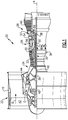
- FIG. 1 schematically illustrates a gas turbine engine 20.
- the gas turbine engine 20 is disclosed herein as a two-spool turbofan that generally incorporates a fan section 22, a compressor section 24, a combustor section 26 and a turbine section 28.
- Alternative engines might include an augmentor section (not shown) among other systems or features.
- the fan section 22 drives air along a bypass flow path B in a bypass duct defined within a nacelle 15, while the compressor section 24 drives air along a core flow path C for compression and communication into the combustor section 26 then expansion through the turbine section 28.
- the exemplary engine 20 generally includes a low speed spool 30 and a high speed spool 32 mounted for rotation about an engine central longitudinal axis A relative to an engine static structure 36 via several bearing systems 38. It should be understood that various bearing systems 38 at various locations may alternatively or additionally be provided, and the location of bearing systems 38 may be varied as appropriate to the application.
- the low speed spool 30 generally includes an inner shaft 40 that interconnects a fan 42, a first (or low) pressure compressor 44 and a first (or low) pressure turbine 46.
- the inner shaft 40 is connected to the fan 42 through a speed change mechanism, which in exemplary gas turbine engine 20 is illustrated as a geared architecture 48 to drive the fan 42 at a lower speed than the low speed spool 30.
- the high speed spool 32 includes an outer shaft 50 that interconnects a second (or high) pressure compressor 52 and a second (or high) pressure turbine 54.
- a combustor 56 is arranged in exemplary gas turbine 20 between the high pressure compressor 52 and the high pressure turbine 54.
- a mid-turbine frame 57 of the engine static structure 36 is arranged generally between the high pressure turbine 54 and the low pressure turbine 46.
- the mid-turbine frame 57 further supports bearing systems 38 in the turbine section 28.
- the inner shaft 40 and the outer shaft 50 are concentric and rotate via bearing systems 38 about the engine central longitudinal axis A which is collinear with their longitudinal axes.
- the core airflow is compressed by the low pressure compressor 44 then the high pressure compressor 52, mixed and burned with fuel in the combustor 56, then expanded over the high pressure turbine 54 and low pressure turbine 46.
- the mid-turbine frame 57 includes airfoils 59 which are in the core airflow path C.
- the turbines 46, 54 rotationally drive the respective low speed spool 30 and high speed spool 32 in response to the expansion.
- gear system 48 may be located aft of combustor section 26 or even aft of turbine section 28, and fan section 22 may be positioned forward or aft of the location of gear system 48.
- the engine 20 in one example is a high-bypass geared aircraft engine.
- the engine 20 bypass ratio is greater than about six, with an example embodiment being greater than about ten
- the geared architecture 48 is an epicyclic gear train, such as a planetary gear system or other gear system, with a gear reduction ratio of greater than about 2.3 and the low pressure turbine 46 has a pressure ratio that is greater than about five.
- the engine 20 bypass ratio is greater than about ten
- the fan diameter is significantly larger than that of the low pressure compressor 44
- the low pressure turbine 46 has a pressure ratio that is greater than about five.
- Low pressure turbine 46 pressure ratio is pressure measured prior to inlet of low pressure turbine 46 as related to the pressure at the outlet of the low pressure turbine 46 prior to an exhaust nozzle.
- the geared architecture 48 may be an epicycle gear train, such as a planetary gear system or other gear system, with a gear reduction ratio of greater than about 2.3:1. It should be understood, however, that the above parameters are only exemplary of one embodiment of a geared architecture engine and that the present invention is applicable to other gas turbine engines including direct drive turbofans.
- the fan section 22 of the engine 20 is designed for a particular flight condition -- typically cruise at about 0.8 Mach and about 35,000 feet (10,668 meters).
- the flight condition of 0.8 Mach and 35,000 ft (10,668 meters), with the engine at its best fuel consumption - also known as "bucket cruise Thrust Specific Fuel Consumption ('TSFC')" - is the industry standard parameter of Ibm of fuel being burned divided by lbf of thrust the engine produces at that minimum point.
- "Low fan pressure ratio” is the pressure ratio across the fan blade alone, without a Fan Exit Guide Vane (“FEGV”) system.
- the low fan pressure ratio as disclosed herein according to one non-limiting embodiment is less than about 1.45.
- the "Low corrected fan tip speed” as disclosed herein according to one non-limiting embodiment is less than about 1150 ft / second (350.5 meters/second).
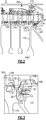
- FIG. 2 shows a high pressure compressor section 100. Airflow 102 at a radial midpoint of the compressor section is shown along with an airflow 104, which is at a radially inner location. As known, there is a temperature differential between airflows 102 and 104, with airflow 102 being generally cooler than airflow 104.
- a last stage compressor blade row 106 is shown adjacent to an exit guide vane row 108.
- exit guide vane 108 is mounted on a housing member 109.
- a hub 110 rotates with the blade row 106.
- Hub 110 is a challenging location due to the high temperature induced stresses mentioned above.
- a sacrificial seal piece 114 may be mounted at a location downstream of the ditch 112.
- a non-contact seal 116 is mounted radially inward of the housing 109 to seal between the hub 110 and the housing 109. As shown, this non-contact seal 116 may have knife-edge seal portions 117.
- a snap ring 118 may mount the seal 116 on the housing 109.
- the member 114 is sacrificial and may be removed once worn. Alternatively, a coating may be placed on the hub 110 at this location as the sacrificial seal piece.
- seal 116 could rotate with the hub 110 and the sacrificial piece could be mounted on the housing 109.
- the seal 116 limits the flow of the hot gas 104 to a chamber 121 where it will heat the hub 110 and eventually lead downstream towards the turbine section.
- FIG. 3 shows an alternative embodiment wherein some of the mid span airflow 102 is tapped through cooling holes 122 and/or 124 in the exit guide vane 108. Cooling hole 122 is at an upstream end of the exit guide vane and hole 124 is at a downstream end. The airflow flows inwardly, as shown at 126, and through a gap 128 into the chamber 121.
- the airflow also flows, as shown at 130 to cool the ditch 112 and hub 110, and then upwardly, as shown at 132, into a gap 119 to resist the flow of the hotter air 104 from moving downwardly towards the ditch 112.
- This arrangement significantly cools the temperature of air that the hub 110 is exposed to along the ditch 112 and radially outwardly.
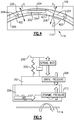
- the seal 116 provides a spring force, shown schematically at S, biases a seal shoe 206 toward a neutral position.
- the housing 109 is shown mounting seal 116.
- the spring force is created as the shoe 206 is otherwise biased toward and away from the sacrificial piece 114. That is, there is a natural position of the shoe 206 relative to a carrier 220, and, as it moves away from this position in either direction, it creates an opposing bias force.
- the illustrated seal may be a HALOTM seal available from ATGI, Advanced Technologies Group, Inc. of Stuart, Florida.
- the HALOTM seal 116 as shown in Figures 4 and 5 has inner shoes 206, and an outer carrier 220.
- the outer carrier 220 and the shoes 206 are generally formed from a single piece of metal, and are cut as shown at 204 such that the combined seal 116 is formed into segments.
- the cuts 204 actually provide a gap that allow arms associated with the seal to provide a spring force, as mentioned below.
- the gaps provided by the cut 204 are relatively small, for example less than .050" (.127 cm).
- the spring force S is shown schematically. As shown in Figure 4 , there are portions of three adjacent segments 401, 402, 403, which come together to form the overall seal 116.
- a cavity 202 receives pressurized air.
- a spring force biases the seal shoe 206 toward a neutral position.
- the spring force is created as the shoe 206 is otherwise biased toward and away from the rotating component 114. That is, there is a natural position of the shoe 206 relative to the carrier 220, and, as it moves away from this position in either direction, it creates an opposing bias force.
- seals are shown on the static housing, they may also rotate with the rotor and seal on static housing. While one particular seal is shown, other types of seals may be utilized.
Landscapes
- Engineering & Computer Science (AREA)
- Mechanical Engineering (AREA)
- General Engineering & Computer Science (AREA)
- Physics & Mathematics (AREA)
- Thermal Sciences (AREA)
- Structures Of Non-Positive Displacement Pumps (AREA)
Abstract
Description
- This application relates to a sealing arrangement wherein a non-contact seal is placed between a rotor hub and a compressor exit guide vane.
- Gas turbine engines are known and typically include a fan delivering air into a compressor and into a bypass duct. The air is compressed in the compressor and delivered into a combustion section where it is mixed with fuel and ignited. Products of this combustion pass downstream over turbine rotors driving them to rotate.
- There are many challenges with the compressor design. One challenge is to increase the pressure and temperature of the air leaving the last stage of the compressor. However, a hub which rotates with compressor blades experiences stresses as this temperature increases.
- In a featured embodiment, a gas turbine engine compressor section has a hub carrying a last row of compressor blades. A compressor exit guide vane is downstream of the last (i.e. most downstream or aft) row or stage of compressor blades. A housing is radially inward of the compressor exit guide vane. A non-contact seal is positioned on one of the housing and the hub.
- In another embodiment according to the previous embodiment, a sacrificial piece is located on the other of the housing and the hub.
- In another embodiment according to any of the previous embodiments, the sacrificial piece is removable from the one of the housing and the hub.
- In another embodiment according to any of the previous embodiments, the non-contact seal is mounted on the housing and seals on a radially outer surface of the sacrificial piece.
- In another embodiment according to any of the previous embodiments, the non-contact seal has a plurality of circumferentially spaced shoes biased radially toward the sacrificial piece.
- In another embodiment according to any of the previous embodiments, the air feed holes are included to tap air from a radially mid span of the compressor section through the housing, and to pass along the hub to resist flow of air radially inward of a gap between the last row of compressor blades and the housing from a radially inner, hotter location along the compressor blades.
- In another embodiment according to any of the previous embodiments, the tapped air is tapped through the compressor exit guide vane.
- In another embodiment according to any of the previous embodiments, at least some of the air feed holes are tapped from an upstream end of compressor exit guide vane.
- In another embodiment according to any of the previous embodiments, at least some of the air feed holes are tapped from a downstream end of the compressor exit guide vane.
- In another embodiment according to any of the previous embodiments, the tapped air also passes through a controlled leakage path between the non-contact seal and the sacrificial piece to pass into a chamber downstream and towards a turbine section.
- In another embodiment according to any of the previous embodiments, there is a ditch in the hub downstream of the last row of compressor blades and the tapped air passes into the ditch, cooling the hub along the ditch, and then flows radially outwardly towards the gap.
- In another embodiment according to any of the previous embodiments, the non-contact seal has a plurality of circumferentially spaced shoes biased radially toward the sacrificial piece.
- In another embodiment according to any of the previous embodiments, air feed holes are included to tap air from a radially mid span of the compressor section through the housing, and to pass along the hub to resist flow of air radially inward of a gap between the last row of compressor blades and the housing from a radially inner, hotter location along the compressor blades.
- In another embodiment according to any of the previous embodiments, the tapped air is tapped through the compressor exit guide vane.
- In another embodiment according to any of the previous embodiments, the tapped air also passes through a controlled leakage path between the non-contact seal and the sacrificial piece to pass into a chamber downstream and towards a turbine section.
- In another embodiment according to any of the previous embodiments, wherein there is a ditch in the hub downstream of the last row of compressor blades and the tapped air passes into the ditch, cooling the hub along the ditch, and then flowing radially outwardly towards the gap.
- In another embodiment according to any of the previous embodiments, air feed holes are included to tap air from a radially mid span of the compressor section through the housing, and to pass along the hub to resist flow of air into a gap between the last row of compressor blades and the housing from a radially inner, hotter location along the compressor blades.
- In another embodiment according to any of the previous embodiments, the tapped air is tapped through the compressor exit guide vane.
- In another embodiment according to any of the previous embodiments, at least some of the air feed holes are tapped from an upstream end of compressor exit guide vane.
- In another embodiment according to any of the previous embodiments, at least some of the air feed holes are tapped from a downstream end of the compressor exit guide vane.
- These and other features may be best understood from the following drawings and specification.
-
-
Figure 1 shows a schematic view of a gas turbine engine. -
Figure 2 shows an arrangement at a downstream end of a high pressure compressor. -
Figure 3 shows an optional detail that may be incorporated into the downstream end of the compressor. -
Figure 4 shows a seal embodiment. -
Figure 5 shows a schematic view of theFigure 4 seal. -
Figure 1 schematically illustrates agas turbine engine 20. Thegas turbine engine 20 is disclosed herein as a two-spool turbofan that generally incorporates afan section 22, acompressor section 24, a combustor section 26 and aturbine section 28. Alternative engines might include an augmentor section (not shown) among other systems or features. Thefan section 22 drives air along a bypass flow path B in a bypass duct defined within anacelle 15, while thecompressor section 24 drives air along a core flow path C for compression and communication into the combustor section 26 then expansion through theturbine section 28. Although depicted as a two-spool turbofan gas turbine engine in the disclosed non-limiting embodiment, it should be understood that the concepts described herein are not limited to use with two-spool turbofans as the teachings may be applied to other types of turbine engines including three-spool architectures. - The
exemplary engine 20 generally includes alow speed spool 30 and ahigh speed spool 32 mounted for rotation about an engine central longitudinal axis A relative to an enginestatic structure 36 viaseveral bearing systems 38. It should be understood thatvarious bearing systems 38 at various locations may alternatively or additionally be provided, and the location ofbearing systems 38 may be varied as appropriate to the application. - The
low speed spool 30 generally includes aninner shaft 40 that interconnects afan 42, a first (or low)pressure compressor 44 and a first (or low)pressure turbine 46. Theinner shaft 40 is connected to thefan 42 through a speed change mechanism, which in exemplarygas turbine engine 20 is illustrated as a gearedarchitecture 48 to drive thefan 42 at a lower speed than thelow speed spool 30. Thehigh speed spool 32 includes anouter shaft 50 that interconnects a second (or high)pressure compressor 52 and a second (or high)pressure turbine 54. Acombustor 56 is arranged inexemplary gas turbine 20 between thehigh pressure compressor 52 and thehigh pressure turbine 54. Amid-turbine frame 57 of the enginestatic structure 36 is arranged generally between thehigh pressure turbine 54 and thelow pressure turbine 46. Themid-turbine frame 57 further supports bearingsystems 38 in theturbine section 28. Theinner shaft 40 and theouter shaft 50 are concentric and rotate viabearing systems 38 about the engine central longitudinal axis A which is collinear with their longitudinal axes. - The core airflow is compressed by the
low pressure compressor 44 then thehigh pressure compressor 52, mixed and burned with fuel in thecombustor 56, then expanded over thehigh pressure turbine 54 andlow pressure turbine 46. Themid-turbine frame 57 includesairfoils 59 which are in the core airflow path C. Theturbines low speed spool 30 andhigh speed spool 32 in response to the expansion. It will be appreciated that each of the positions of thefan section 22,compressor section 24, combustor section 26,turbine section 28, and fandrive gear system 48 may be varied. For example,gear system 48 may be located aft of combustor section 26 or even aft ofturbine section 28, andfan section 22 may be positioned forward or aft of the location ofgear system 48. - The
engine 20 in one example is a high-bypass geared aircraft engine. In a further example, theengine 20 bypass ratio is greater than about six, with an example embodiment being greater than about ten, the gearedarchitecture 48 is an epicyclic gear train, such as a planetary gear system or other gear system, with a gear reduction ratio of greater than about 2.3 and thelow pressure turbine 46 has a pressure ratio that is greater than about five. In one disclosed embodiment, theengine 20 bypass ratio is greater than about ten, the fan diameter is significantly larger than that of thelow pressure compressor 44, and thelow pressure turbine 46 has a pressure ratio that is greater than about five.Low pressure turbine 46 pressure ratio is pressure measured prior to inlet oflow pressure turbine 46 as related to the pressure at the outlet of thelow pressure turbine 46 prior to an exhaust nozzle. The gearedarchitecture 48 may be an epicycle gear train, such as a planetary gear system or other gear system, with a gear reduction ratio of greater than about 2.3:1. It should be understood, however, that the above parameters are only exemplary of one embodiment of a geared architecture engine and that the present invention is applicable to other gas turbine engines including direct drive turbofans. - A significant amount of thrust is provided by the bypass flow B due to the high bypass ratio. The
fan section 22 of theengine 20 is designed for a particular flight condition -- typically cruise at about 0.8 Mach and about 35,000 feet (10,668 meters). The flight condition of 0.8 Mach and 35,000 ft (10,668 meters), with the engine at its best fuel consumption - also known as "bucket cruise Thrust Specific Fuel Consumption ('TSFC')" - is the industry standard parameter of Ibm of fuel being burned divided by lbf of thrust the engine produces at that minimum point. "Low fan pressure ratio" is the pressure ratio across the fan blade alone, without a Fan Exit Guide Vane ("FEGV") system. The low fan pressure ratio as disclosed herein according to one non-limiting embodiment is less than about 1.45. "Low corrected fan tip speed" is the actual fan tip speed in ft/sec divided by an industry standard temperature correction of [(Tram °R) / (518.7 °R)]0.5 (where °R = K x 9/5). The "Low corrected fan tip speed" as disclosed herein according to one non-limiting embodiment is less than about 1150 ft / second (350.5 meters/second). -
Figure 2 shows a highpressure compressor section 100.Airflow 102 at a radial midpoint of the compressor section is shown along with anairflow 104, which is at a radially inner location. As known, there is a temperature differential betweenairflows airflow 102 being generally cooler thanairflow 104. - A last stage
compressor blade row 106 is shown adjacent to an exitguide vane row 108. As shown,exit guide vane 108 is mounted on ahousing member 109. Ahub 110 rotates with theblade row 106.Hub 110 is a challenging location due to the high temperature induced stresses mentioned above. As shown, there is aditch 112 at a downstream end of thehub 110. Asacrificial seal piece 114 may be mounted at a location downstream of theditch 112. Anon-contact seal 116 is mounted radially inward of thehousing 109 to seal between thehub 110 and thehousing 109. As shown, thisnon-contact seal 116 may have knife-edge seal portions 117. Asnap ring 118 may mount theseal 116 on thehousing 109. Themember 114 is sacrificial and may be removed once worn. Alternatively, a coating may be placed on thehub 110 at this location as the sacrificial seal piece. - Of course, the
seal 116 could rotate with thehub 110 and the sacrificial piece could be mounted on thehousing 109. Theseal 116 limits the flow of thehot gas 104 to achamber 121 where it will heat thehub 110 and eventually lead downstream towards the turbine section. -
Figure 3 shows an alternative embodiment wherein some of themid span airflow 102 is tapped throughcooling holes 122 and/or 124 in theexit guide vane 108.Cooling hole 122 is at an upstream end of the exit guide vane andhole 124 is at a downstream end. The airflow flows inwardly, as shown at 126, and through agap 128 into thechamber 121. - The airflow also flows, as shown at 130 to cool the
ditch 112 andhub 110, and then upwardly, as shown at 132, into agap 119 to resist the flow of thehotter air 104 from moving downwardly towards theditch 112. This arrangement significantly cools the temperature of air that thehub 110 is exposed to along theditch 112 and radially outwardly. - As shown in
Figure 4 , theseal 116 provides a spring force, shown schematically at S, biases aseal shoe 206 toward a neutral position. Thehousing 109 is shown mountingseal 116. The spring force is created as theshoe 206 is otherwise biased toward and away from thesacrificial piece 114. That is, there is a natural position of theshoe 206 relative to acarrier 220, and, as it moves away from this position in either direction, it creates an opposing bias force. - The illustrated seal may be a HALO™ seal available from ATGI, Advanced Technologies Group, Inc. of Stuart, Florida. The
HALO™ seal 116 as shown inFigures 4 and 5 hasinner shoes 206, and anouter carrier 220. Theouter carrier 220 and theshoes 206 are generally formed from a single piece of metal, and are cut as shown at 204 such that the combinedseal 116 is formed into segments. As shown, thecuts 204 actually provide a gap that allow arms associated with the seal to provide a spring force, as mentioned below. The gaps provided by thecut 204 are relatively small, for example less than .050" (.127 cm). The spring force S is shown schematically. As shown inFigure 4 , there are portions of threeadjacent segments overall seal 116. Acavity 202 receives pressurized air. - As shown in
Figure 5 , a spring force, shown schematically at 225, biases theseal shoe 206 toward a neutral position. The spring force is created as theshoe 206 is otherwise biased toward and away from therotating component 114. That is, there is a natural position of theshoe 206 relative to thecarrier 220, and, as it moves away from this position in either direction, it creates an opposing bias force. - As can be appreciated from
Figures 4 , taken into combination withFigure 5 , air is injected into thecavity 202, and biases theshoe 206 toward thesacrificial piece 114. Thus, there is astatic pressure force 208 forcing theshoe 206 toward the rotor, and an opposingspring force 225 tending to restore the shoe to a neutral position. In addition, adynamic pressure 210, whose magnitude depends on the proximity of the shoe to the rotor, forces the shoe away from the rotor. - These three forces come into equilibrium to center the shoe at a desired location relative to the rotor such that any disturbance to the system will tend to redistribute the forces in a manner that works to restore the shoe to the same material position as prior to the disturbance. In this way, it is self-adjusting, and without need of any external control. These types of self-adjusting non-contacting seals effectively minimize both axi-symmetric (all shoes of the ring behave in the same manner) and non-axisymmetric (each shoe of the ring behaves independent of its neighbors) clearances. As such, these seals achieve very low leakage rates which enable the provision of thrust balance cavities in an effective and efficient manner.
- While the seals are shown on the static housing, they may also rotate with the rotor and seal on static housing. While one particular seal is shown, other types of seals may be utilized.
- Although an embodiment of this invention has been disclosed, a worker of ordinary skill in this art would recognize that certain modifications would come within the scope of this invention. For that reason, the following claims should be studied to determine the true scope and content of this invention.
Claims (11)
- A gas turbine engine compressor section (100) comprising:a hub (110) carrying a last row of compressor blades (106);a compressor exit guide vane (108) downstream of said last row of compressor blades (106);a housing (109) radially inward of said compressor exit guide vane (108); anda non-contact seal (116) positioned on one of said housing (109) and said hub (110).
- The gas turbine engine compressor section (100) as set forth in claim 1, wherein a sacrificial piece (114) is located on the other of said housing (109) and said hub (110).
- The gas turbine engine compressor section (100) as set forth in claim 2, wherein said sacrificial piece (114) is removable from said one of said housing (109) and said hub (110).
- The gas turbine engine compressor section (100) as set forth in claim 2 or 3, wherein said non-contact seal (116) is mounted on said housing (109) and seals on a radially outer surface of said sacrificial piece (114).
- The gas turbine engine compressor section (100) as set forth in claim 2, 3 or 4, wherein said non-contact seal (116) has a plurality of circumferentially spaced shoes (206) biased radially toward said sacrificial piece (114).
- The gas turbine engine compressor section (100) as set forth in any preceding claim, wherein air feed holes (122, 124) are included to tap air from a radially mid span of said compressor section (100) through said housing (109), and to pass air along said hub (110) to resist flow of air radially inward of a gap (119) between said last row of compressor blades (106) and said housing (109) from a radially inner, hotter location along said compressor blades (106).
- The gas turbine engine compressor section (100) as set forth in claim 6, wherein said tapped air is tapped through said compressor exit guide vane (108).
- The gas turbine engine compressor section (100) as set forth in claim 7, wherein at least some of said air feed holes (122, 124) are tapped from an upstream end of compressor exit guide vane (108).
- The gas turbine engine compressor section (100) as set forth in claim 7 or 8, wherein at least some of said air feed holes (122, 124) are tapped from a downstream end of said compressor exit guide vane (108).
- The gas turbine engine compressor section (100) as set forth in claim 7, 8 or 9, wherein said tapped air also passes through a controlled leakage path between said non-contact seal (116) and said sacrificial piece (114) to pass into a chamber downstream and towards a turbine section (28).
- The gas turbine engine compressor section (100) as set forth in any of claims 7 to 10, wherein there is a ditch (112) in said hub (110) downstream of said last row of compressor blades (106) and said tapped air passes into said ditch (112), cooling said hub (110) along said ditch (112), and then flowing radially outwardly towards said gap (119).
Applications Claiming Priority (1)
| Application Number | Priority Date | Filing Date | Title |
|---|---|---|---|
| US14/934,303 US20170130732A1 (en) | 2015-11-06 | 2015-11-06 | Compressor exit seal |
Publications (2)
| Publication Number | Publication Date |
|---|---|
| EP3165717A1 true EP3165717A1 (en) | 2017-05-10 |
| EP3165717B1 EP3165717B1 (en) | 2020-01-01 |
Family
ID=57226915
Family Applications (1)
| Application Number | Title | Priority Date | Filing Date |
|---|---|---|---|
| EP16197401.9A Active EP3165717B1 (en) | 2015-11-06 | 2016-11-04 | Compressor exit seal |
Country Status (2)
| Country | Link |
|---|---|
| US (1) | US20170130732A1 (en) |
| EP (1) | EP3165717B1 (en) |
Families Citing this family (5)
| Publication number | Priority date | Publication date | Assignee | Title |
|---|---|---|---|---|
| US8641366B1 (en) * | 2013-03-07 | 2014-02-04 | United Technologies Corporation | Non-contacting seals for geared gas turbine engine bearing compartments |
| US10443443B2 (en) * | 2013-03-07 | 2019-10-15 | United Technologies Corporation | Non-contacting seals for geared gas turbine engine bearing compartments |
| US10731761B2 (en) | 2017-07-14 | 2020-08-04 | Raytheon Technologies Corporation | Hydrostatic non-contact seal with offset outer ring |
| US10830081B2 (en) * | 2017-07-17 | 2020-11-10 | Raytheon Technologies Corporation | Non-contact seal with non-straight spring beam(s) |
| US11203934B2 (en) | 2019-07-30 | 2021-12-21 | General Electric Company | Gas turbine engine with separable shaft and seal assembly |
Citations (4)
| Publication number | Priority date | Publication date | Assignee | Title |
|---|---|---|---|---|
| EP2570633A2 (en) * | 2011-09-16 | 2013-03-20 | United Technologies Corporation | Thrust bearing system with inverted non-contacting dynamic seals for gas turbine engine |
| US20130195627A1 (en) * | 2012-01-27 | 2013-08-01 | Jorn A. Glahn | Thrust balance system for gas turbine engine |
| US20130259659A1 (en) * | 2012-03-27 | 2013-10-03 | Pratt & Whitney | Knife Edge Seal for Gas Turbine Engine |
| US8641366B1 (en) * | 2013-03-07 | 2014-02-04 | United Technologies Corporation | Non-contacting seals for geared gas turbine engine bearing compartments |
Family Cites Families (8)
| Publication number | Priority date | Publication date | Assignee | Title |
|---|---|---|---|---|
| DE1938132A1 (en) * | 1969-07-26 | 1971-01-28 | Daimler Benz Ag | Guide vanes of axial compressors |
| DE2042478C3 (en) * | 1970-08-27 | 1975-08-14 | Motoren- Und Turbinen-Union Muenchen Gmbh, 8000 Muenchen | Gas turbine engine, preferably jet engine for aircraft, with cooling air and optionally sealing air extraction |
| GB2251031B (en) * | 1990-12-19 | 1995-01-18 | Rolls Royce Plc | Cooling air pick up |
| US8002285B2 (en) * | 2003-05-01 | 2011-08-23 | Justak John F | Non-contact seal for a gas turbine engine |
| FR2875866B1 (en) * | 2004-09-30 | 2006-12-08 | Snecma Moteurs Sa | AIR CIRCULATION METHOD IN A TURBOMACHINE COMPRESSOR, COMPRESSOR ARRANGEMENT USING THE SAME, COMPRESSION STAGE AND COMPRESSOR COMPRISING SUCH ARRANGEMENT, AND AIRCRAFT ENGINE EQUIPPED WITH SUCH A COMPRESSOR |
| EP2450531B1 (en) * | 2010-11-04 | 2013-05-15 | Siemens Aktiengesellschaft | Cooling of an axial compressor |
| EP2458157B1 (en) * | 2010-11-30 | 2015-10-14 | Techspace Aero S.A. | Abradable interior stator ferrule |
| US9097350B2 (en) * | 2012-04-02 | 2015-08-04 | United Technologies Corporation | Axial non-contact seal |
-
2015
- 2015-11-06 US US14/934,303 patent/US20170130732A1/en not_active Abandoned
-
2016
- 2016-11-04 EP EP16197401.9A patent/EP3165717B1/en active Active
Patent Citations (4)
| Publication number | Priority date | Publication date | Assignee | Title |
|---|---|---|---|---|
| EP2570633A2 (en) * | 2011-09-16 | 2013-03-20 | United Technologies Corporation | Thrust bearing system with inverted non-contacting dynamic seals for gas turbine engine |
| US20130195627A1 (en) * | 2012-01-27 | 2013-08-01 | Jorn A. Glahn | Thrust balance system for gas turbine engine |
| US20130259659A1 (en) * | 2012-03-27 | 2013-10-03 | Pratt & Whitney | Knife Edge Seal for Gas Turbine Engine |
| US8641366B1 (en) * | 2013-03-07 | 2014-02-04 | United Technologies Corporation | Non-contacting seals for geared gas turbine engine bearing compartments |
Also Published As
| Publication number | Publication date |
|---|---|
| EP3165717B1 (en) | 2020-01-01 |
| US20170130732A1 (en) | 2017-05-11 |
Similar Documents
| Publication | Publication Date | Title |
|---|---|---|
| US9097350B2 (en) | Axial non-contact seal | |
| US10968777B2 (en) | Chordal seal | |
| EP2807345B1 (en) | Thrust balance system for gas turbine engine | |
| US11286790B2 (en) | Cooling passages for gas turbine engine component | |
| EP3102794B1 (en) | Blade outer air seal mount | |
| EP3296511A2 (en) | Gas turbine engine blade, corresponding gas turbine engine and method for a gas turbine engine blade | |
| US10947853B2 (en) | Gas turbine component with platform cooling | |
| EP2977555B1 (en) | Airfoil platform with cooling channels | |
| EP3521572B1 (en) | Hydrostatic seal assembly with abradable teeth for gas turbine engine | |
| EP3068996B1 (en) | Multiple injector holes for gas turbine engine vane | |
| EP3093445B1 (en) | Gas turbine vane and method of forming | |
| EP3165717B1 (en) | Compressor exit seal | |
| EP3734019A1 (en) | Labyrinth seal with passive check valve | |
| EP3112591B1 (en) | Tip shrouded high aspect ratio compressor stage | |
| EP3536903B1 (en) | Cooling passage with structural rib and film cooling slot | |
| EP3190266B1 (en) | Gas turbine engine comprising a rotor hub seal | |
| EP3095971B1 (en) | Support assembly for a gas turbine engine | |
| US20160003163A1 (en) | Gas turbine engine with short transition duct | |
| US20190040753A1 (en) | Gas turbine engine component | |
| EP2995778B1 (en) | Method and assembly for reducing secondary heat in a gas turbine engine | |
| EP3203023A1 (en) | Gas turbine engine with a cooling fluid path | |
| EP3181869B1 (en) | Compressor core inner diameter cooling | |
| US10526897B2 (en) | Cooling passages for gas turbine engine component | |
| US10746032B2 (en) | Transition duct for a gas turbine engine | |
| EP3179034B1 (en) | Multi-source turbine cooling air |
Legal Events
| Date | Code | Title | Description |
|---|---|---|---|
| PUAI | Public reference made under article 153(3) epc to a published international application that has entered the european phase |
Free format text: ORIGINAL CODE: 0009012 |
|
| STAA | Information on the status of an ep patent application or granted ep patent |
Free format text: STATUS: THE APPLICATION HAS BEEN PUBLISHED |
|
| AK | Designated contracting states |
Kind code of ref document: A1 Designated state(s): AL AT BE BG CH CY CZ DE DK EE ES FI FR GB GR HR HU IE IS IT LI LT LU LV MC MK MT NL NO PL PT RO RS SE SI SK SM TR |
|
| AX | Request for extension of the european patent |
Extension state: BA ME |
|
| STAA | Information on the status of an ep patent application or granted ep patent |
Free format text: STATUS: REQUEST FOR EXAMINATION WAS MADE |
|
| 17P | Request for examination filed |
Effective date: 20171110 |
|
| RBV | Designated contracting states (corrected) |
Designated state(s): AL AT BE BG CH CY CZ DE DK EE ES FI FR GB GR HR HU IE IS IT LI LT LU LV MC MK MT NL NO PL PT RO RS SE SI SK SM TR |
|
| RIC1 | Information provided on ipc code assigned before grant |
Ipc: F01D 11/02 20060101ALI20171130BHEP Ipc: F01D 11/00 20060101AFI20171130BHEP |
|
| REG | Reference to a national code |
Ref country code: DE Ref legal event code: R079 Ref document number: 602016027211 Country of ref document: DE Free format text: PREVIOUS MAIN CLASS: F01D0011000000 Ipc: F04D0029080000 |
|
| RIC1 | Information provided on ipc code assigned before grant |
Ipc: F04D 29/54 20060101ALI20180305BHEP Ipc: F01D 11/02 20060101ALI20180305BHEP Ipc: F04D 29/32 20060101ALI20180305BHEP Ipc: F01D 11/00 20060101ALI20180305BHEP Ipc: F04D 29/08 20060101AFI20180305BHEP Ipc: F04D 29/52 20060101ALI20180305BHEP Ipc: F04D 29/58 20060101ALI20180305BHEP |
|
| STAA | Information on the status of an ep patent application or granted ep patent |
Free format text: STATUS: EXAMINATION IS IN PROGRESS |
|
| 17Q | First examination report despatched |
Effective date: 20180516 |
|
| GRAP | Despatch of communication of intention to grant a patent |
Free format text: ORIGINAL CODE: EPIDOSNIGR1 |
|
| STAA | Information on the status of an ep patent application or granted ep patent |
Free format text: STATUS: GRANT OF PATENT IS INTENDED |
|
| INTG | Intention to grant announced |
Effective date: 20190510 |
|
| GRAS | Grant fee paid |
Free format text: ORIGINAL CODE: EPIDOSNIGR3 |
|
| GRAA | (expected) grant |
Free format text: ORIGINAL CODE: 0009210 |
|
| STAA | Information on the status of an ep patent application or granted ep patent |
Free format text: STATUS: THE PATENT HAS BEEN GRANTED |
|
| AK | Designated contracting states |
Kind code of ref document: B1 Designated state(s): AL AT BE BG CH CY CZ DE DK EE ES FI FR GB GR HR HU IE IS IT LI LT LU LV MC MK MT NL NO PL PT RO RS SE SI SK SM TR |
|
| REG | Reference to a national code |
Ref country code: GB Ref legal event code: FG4D |
|
| REG | Reference to a national code |
Ref country code: CH Ref legal event code: EP Ref country code: AT Ref legal event code: REF Ref document number: 1220104 Country of ref document: AT Kind code of ref document: T Effective date: 20200115 |
|
| REG | Reference to a national code |
Ref country code: IE Ref legal event code: FG4D |
|
| REG | Reference to a national code |
Ref country code: DE Ref legal event code: R096 Ref document number: 602016027211 Country of ref document: DE |
|
| REG | Reference to a national code |
Ref country code: NL Ref legal event code: MP Effective date: 20200101 |
|
| REG | Reference to a national code |
Ref country code: LT Ref legal event code: MG4D |
|
| PG25 | Lapsed in a contracting state [announced via postgrant information from national office to epo] |
Ref country code: RS Free format text: LAPSE BECAUSE OF FAILURE TO SUBMIT A TRANSLATION OF THE DESCRIPTION OR TO PAY THE FEE WITHIN THE PRESCRIBED TIME-LIMIT Effective date: 20200101 Ref country code: NO Free format text: LAPSE BECAUSE OF FAILURE TO SUBMIT A TRANSLATION OF THE DESCRIPTION OR TO PAY THE FEE WITHIN THE PRESCRIBED TIME-LIMIT Effective date: 20200401 Ref country code: FI Free format text: LAPSE BECAUSE OF FAILURE TO SUBMIT A TRANSLATION OF THE DESCRIPTION OR TO PAY THE FEE WITHIN THE PRESCRIBED TIME-LIMIT Effective date: 20200101 Ref country code: NL Free format text: LAPSE BECAUSE OF FAILURE TO SUBMIT A TRANSLATION OF THE DESCRIPTION OR TO PAY THE FEE WITHIN THE PRESCRIBED TIME-LIMIT Effective date: 20200101 Ref country code: CZ Free format text: LAPSE BECAUSE OF FAILURE TO SUBMIT A TRANSLATION OF THE DESCRIPTION OR TO PAY THE FEE WITHIN THE PRESCRIBED TIME-LIMIT Effective date: 20200101 Ref country code: PT Free format text: LAPSE BECAUSE OF FAILURE TO SUBMIT A TRANSLATION OF THE DESCRIPTION OR TO PAY THE FEE WITHIN THE PRESCRIBED TIME-LIMIT Effective date: 20200527 Ref country code: LT Free format text: LAPSE BECAUSE OF FAILURE TO SUBMIT A TRANSLATION OF THE DESCRIPTION OR TO PAY THE FEE WITHIN THE PRESCRIBED TIME-LIMIT Effective date: 20200101 |
|
| PG25 | Lapsed in a contracting state [announced via postgrant information from national office to epo] |
Ref country code: SE Free format text: LAPSE BECAUSE OF FAILURE TO SUBMIT A TRANSLATION OF THE DESCRIPTION OR TO PAY THE FEE WITHIN THE PRESCRIBED TIME-LIMIT Effective date: 20200101 Ref country code: BG Free format text: LAPSE BECAUSE OF FAILURE TO SUBMIT A TRANSLATION OF THE DESCRIPTION OR TO PAY THE FEE WITHIN THE PRESCRIBED TIME-LIMIT Effective date: 20200401 Ref country code: LV Free format text: LAPSE BECAUSE OF FAILURE TO SUBMIT A TRANSLATION OF THE DESCRIPTION OR TO PAY THE FEE WITHIN THE PRESCRIBED TIME-LIMIT Effective date: 20200101 Ref country code: IS Free format text: LAPSE BECAUSE OF FAILURE TO SUBMIT A TRANSLATION OF THE DESCRIPTION OR TO PAY THE FEE WITHIN THE PRESCRIBED TIME-LIMIT Effective date: 20200501 Ref country code: GR Free format text: LAPSE BECAUSE OF FAILURE TO SUBMIT A TRANSLATION OF THE DESCRIPTION OR TO PAY THE FEE WITHIN THE PRESCRIBED TIME-LIMIT Effective date: 20200402 Ref country code: HR Free format text: LAPSE BECAUSE OF FAILURE TO SUBMIT A TRANSLATION OF THE DESCRIPTION OR TO PAY THE FEE WITHIN THE PRESCRIBED TIME-LIMIT Effective date: 20200101 |
|
| REG | Reference to a national code |
Ref country code: DE Ref legal event code: R097 Ref document number: 602016027211 Country of ref document: DE |
|
| PG25 | Lapsed in a contracting state [announced via postgrant information from national office to epo] |
Ref country code: DK Free format text: LAPSE BECAUSE OF FAILURE TO SUBMIT A TRANSLATION OF THE DESCRIPTION OR TO PAY THE FEE WITHIN THE PRESCRIBED TIME-LIMIT Effective date: 20200101 Ref country code: ES Free format text: LAPSE BECAUSE OF FAILURE TO SUBMIT A TRANSLATION OF THE DESCRIPTION OR TO PAY THE FEE WITHIN THE PRESCRIBED TIME-LIMIT Effective date: 20200101 Ref country code: SK Free format text: LAPSE BECAUSE OF FAILURE TO SUBMIT A TRANSLATION OF THE DESCRIPTION OR TO PAY THE FEE WITHIN THE PRESCRIBED TIME-LIMIT Effective date: 20200101 Ref country code: RO Free format text: LAPSE BECAUSE OF FAILURE TO SUBMIT A TRANSLATION OF THE DESCRIPTION OR TO PAY THE FEE WITHIN THE PRESCRIBED TIME-LIMIT Effective date: 20200101 Ref country code: SM Free format text: LAPSE BECAUSE OF FAILURE TO SUBMIT A TRANSLATION OF THE DESCRIPTION OR TO PAY THE FEE WITHIN THE PRESCRIBED TIME-LIMIT Effective date: 20200101 Ref country code: EE Free format text: LAPSE BECAUSE OF FAILURE TO SUBMIT A TRANSLATION OF THE DESCRIPTION OR TO PAY THE FEE WITHIN THE PRESCRIBED TIME-LIMIT Effective date: 20200101 |
|
| PLBE | No opposition filed within time limit |
Free format text: ORIGINAL CODE: 0009261 |
|
| STAA | Information on the status of an ep patent application or granted ep patent |
Free format text: STATUS: NO OPPOSITION FILED WITHIN TIME LIMIT |
|
| REG | Reference to a national code |
Ref country code: AT Ref legal event code: MK05 Ref document number: 1220104 Country of ref document: AT Kind code of ref document: T Effective date: 20200101 |
|
| 26N | No opposition filed |
Effective date: 20201002 |
|
| PG25 | Lapsed in a contracting state [announced via postgrant information from national office to epo] |
Ref country code: IT Free format text: LAPSE BECAUSE OF FAILURE TO SUBMIT A TRANSLATION OF THE DESCRIPTION OR TO PAY THE FEE WITHIN THE PRESCRIBED TIME-LIMIT Effective date: 20200101 Ref country code: AT Free format text: LAPSE BECAUSE OF FAILURE TO SUBMIT A TRANSLATION OF THE DESCRIPTION OR TO PAY THE FEE WITHIN THE PRESCRIBED TIME-LIMIT Effective date: 20200101 |
|
| PG25 | Lapsed in a contracting state [announced via postgrant information from national office to epo] |
Ref country code: SI Free format text: LAPSE BECAUSE OF FAILURE TO SUBMIT A TRANSLATION OF THE DESCRIPTION OR TO PAY THE FEE WITHIN THE PRESCRIBED TIME-LIMIT Effective date: 20200101 Ref country code: PL Free format text: LAPSE BECAUSE OF FAILURE TO SUBMIT A TRANSLATION OF THE DESCRIPTION OR TO PAY THE FEE WITHIN THE PRESCRIBED TIME-LIMIT Effective date: 20200101 |
|
| PG25 | Lapsed in a contracting state [announced via postgrant information from national office to epo] |
Ref country code: MC Free format text: LAPSE BECAUSE OF FAILURE TO SUBMIT A TRANSLATION OF THE DESCRIPTION OR TO PAY THE FEE WITHIN THE PRESCRIBED TIME-LIMIT Effective date: 20200101 |
|
| REG | Reference to a national code |
Ref country code: CH Ref legal event code: PL |
|
| PG25 | Lapsed in a contracting state [announced via postgrant information from national office to epo] |
Ref country code: LU Free format text: LAPSE BECAUSE OF NON-PAYMENT OF DUE FEES Effective date: 20201104 |
|
| REG | Reference to a national code |
Ref country code: BE Ref legal event code: MM Effective date: 20201130 |
|
| PG25 | Lapsed in a contracting state [announced via postgrant information from national office to epo] |
Ref country code: LI Free format text: LAPSE BECAUSE OF NON-PAYMENT OF DUE FEES Effective date: 20201130 Ref country code: CH Free format text: LAPSE BECAUSE OF NON-PAYMENT OF DUE FEES Effective date: 20201130 |
|
| PG25 | Lapsed in a contracting state [announced via postgrant information from national office to epo] |
Ref country code: IE Free format text: LAPSE BECAUSE OF NON-PAYMENT OF DUE FEES Effective date: 20201104 |
|
| PG25 | Lapsed in a contracting state [announced via postgrant information from national office to epo] |
Ref country code: TR Free format text: LAPSE BECAUSE OF FAILURE TO SUBMIT A TRANSLATION OF THE DESCRIPTION OR TO PAY THE FEE WITHIN THE PRESCRIBED TIME-LIMIT Effective date: 20200101 Ref country code: MT Free format text: LAPSE BECAUSE OF FAILURE TO SUBMIT A TRANSLATION OF THE DESCRIPTION OR TO PAY THE FEE WITHIN THE PRESCRIBED TIME-LIMIT Effective date: 20200101 Ref country code: CY Free format text: LAPSE BECAUSE OF FAILURE TO SUBMIT A TRANSLATION OF THE DESCRIPTION OR TO PAY THE FEE WITHIN THE PRESCRIBED TIME-LIMIT Effective date: 20200101 |
|
| PG25 | Lapsed in a contracting state [announced via postgrant information from national office to epo] |
Ref country code: MK Free format text: LAPSE BECAUSE OF FAILURE TO SUBMIT A TRANSLATION OF THE DESCRIPTION OR TO PAY THE FEE WITHIN THE PRESCRIBED TIME-LIMIT Effective date: 20200101 Ref country code: AL Free format text: LAPSE BECAUSE OF FAILURE TO SUBMIT A TRANSLATION OF THE DESCRIPTION OR TO PAY THE FEE WITHIN THE PRESCRIBED TIME-LIMIT Effective date: 20200101 |
|
| PG25 | Lapsed in a contracting state [announced via postgrant information from national office to epo] |
Ref country code: BE Free format text: LAPSE BECAUSE OF NON-PAYMENT OF DUE FEES Effective date: 20201130 |
|
| REG | Reference to a national code |
Ref country code: DE Ref legal event code: R081 Ref document number: 602016027211 Country of ref document: DE Owner name: RAYTHEON TECHNOLOGIES CORPORATION (N.D.GES.D.S, US Free format text: FORMER OWNER: UNITED TECHNOLOGIES CORPORATION, FARMINGTON, CONN., US Ref country code: DE Ref legal event code: R081 Ref document number: 602016027211 Country of ref document: DE Owner name: RTX CORPORATION (N.D.GES.D. STAATES DELAWARE),, US Free format text: FORMER OWNER: UNITED TECHNOLOGIES CORPORATION, FARMINGTON, CONN., US |
|
| P01 | Opt-out of the competence of the unified patent court (upc) registered |
Effective date: 20230520 |
|
| REG | Reference to a national code |
Ref country code: DE Ref legal event code: R081 Ref document number: 602016027211 Country of ref document: DE Owner name: RTX CORPORATION (N.D.GES.D. STAATES DELAWARE),, US Free format text: FORMER OWNER: RAYTHEON TECHNOLOGIES CORPORATION (N.D.GES.D.STAATES DELAWARE), ARLINGTON, VA, US |
|
| PGFP | Annual fee paid to national office [announced via postgrant information from national office to epo] |
Ref country code: DE Payment date: 20251022 Year of fee payment: 10 |
|
| PGFP | Annual fee paid to national office [announced via postgrant information from national office to epo] |
Ref country code: GB Payment date: 20251023 Year of fee payment: 10 |
|
| PGFP | Annual fee paid to national office [announced via postgrant information from national office to epo] |
Ref country code: FR Payment date: 20251022 Year of fee payment: 10 |