EP3165650B1 - Sinker equipped with lubrication oil channeling and separating structure - Google Patents
Sinker equipped with lubrication oil channeling and separating structure Download PDFInfo
- Publication number
- EP3165650B1 EP3165650B1 EP15193335.5A EP15193335A EP3165650B1 EP 3165650 B1 EP3165650 B1 EP 3165650B1 EP 15193335 A EP15193335 A EP 15193335A EP 3165650 B1 EP3165650 B1 EP 3165650B1
- Authority
- EP
- European Patent Office
- Prior art keywords
- sinker
- oil
- knitting
- channeling
- lubrication oil
- Prior art date
- Legal status (The legal status is an assumption and is not a legal conclusion. Google has not performed a legal analysis and makes no representation as to the accuracy of the status listed.)
- Active
Links
- 238000005461 lubrication Methods 0.000 title claims description 51
- 230000005465 channeling Effects 0.000 title claims description 40
- 238000009940 knitting Methods 0.000 claims description 57
- 230000000903 blocking effect Effects 0.000 claims description 22
- 239000004744 fabric Substances 0.000 description 11
- 238000007796 conventional method Methods 0.000 description 3
- 230000007547 defect Effects 0.000 description 2
- 238000000034 method Methods 0.000 description 2
- 229920000742 Cotton Polymers 0.000 description 1
- 238000010276 construction Methods 0.000 description 1
- 238000001816 cooling Methods 0.000 description 1
- 230000000694 effects Effects 0.000 description 1
- 230000002035 prolonged effect Effects 0.000 description 1
- 238000000926 separation method Methods 0.000 description 1
Images



Classifications
-
- D—TEXTILES; PAPER
- D04—BRAIDING; LACE-MAKING; KNITTING; TRIMMINGS; NON-WOVEN FABRICS
- D04B—KNITTING
- D04B35/00—Details of, or auxiliary devices incorporated in, knitting machines, not otherwise provided for
- D04B35/28—Devices for lubricating machine parts
-
- D—TEXTILES; PAPER
- D04—BRAIDING; LACE-MAKING; KNITTING; TRIMMINGS; NON-WOVEN FABRICS
- D04B—KNITTING
- D04B15/00—Details of, or auxiliary devices incorporated in, weft knitting machines, restricted to machines of this kind
- D04B15/06—Sinkers
Definitions
- the present invention relates to a sinker of knitting machines and particularly to a sinker equipped with lubrication oil channeling and separating structure.
- a conventional sinker 10 on a knitting machine generally can be moved reciprocally to-and- fro by driving a nub 11 formed thereon.
- the sinker 10 is in operation reciprocally for a prolonged period of time, other portions of the sinker 11 such as the push friction end 101, first driving friction end 111, second driving friction end 112 and loading friction end 121 have to be properly cooled and lubricated.
- the most common approach at present is applying lubrication oil.
- the sinker 10 includes an oil sprinkling zone 14 to receive lubrication oil 71 sprinkled from an oil ejection nozzle 70, and the lubrication oil 71 flows downward after sprinkling to cool and lubricate the push friction end 101, first driving friction end 111, second driving friction end 112 and loading friction end 121.
- the design and structure of the conventional sinker 10 often do not take into account of the lubrication oil could flow to the knitting portion 13, yarns in the knitting portion 13 could be smeared by the lubrication oil during knitting operation and result in increasing of quality defects of the knitting fabrics.
- Taiwan patent No. M365935 discloses an improvement for a sinker that mainly includes a flank, a nose at an upper side of the rear end of the flank, a nose located at a upper side of a rear end of the flank, a guide portion at a lower side of the rear end, and a notch at the bottom edge of the flank that can be formed in a square, a trapezoid, an arc or other shapes.
- the notch also shapes the bottom edge of the flank to form a front bottom edge and a rear bottom edge.
- the guide portion and the flank are spaced from each other.
- the guide portion is jutting at a length to cover the notch, namely the jutting portion of the guide portion includes a front end formed at a size slightly greater than or equal to the location distance of the front end wall of the notch.
- the guide portion is located below the rear end of the flank.
- the sinker also includes a guiding nub at the read side. Through the aforesaid structure when the sinker and its corresponding knitting needle are in knitting operation they can be positioned at the notch to fend off lubrication oil.
- DE 33 25 103 A1 discloses a holding-down sinker for knitting machines which is equipped, in its front part guided in a groove, with a bearing region limited on both sides by sharp-edged steps and coordinated in its length with the length of the guide groove and with the stroke length of the holding-down sinker. Its control foot located in the middle region is connected, via narrow connecting webs formed by lower and upper edge recesses, respectively to the front sinker part and the rear sinker part, which impart elasticity to the control foot in the stroke direction of the holding-down sinker.
- GB 2 134 142 A discloses a sinker for a sinker top latch needle circular knitting machine having a nose and an operating butt at opposite ends thereof, and being generally similar to a conventional sinker except that it has cut-out portions and in a bottom edge thereof between the nose and the butt.
- the cut-out portions provide non-continuous contact and reduced friction between the bottom edge and adjoining side faces of the sinker respectively with a bottom wall and side walls of a sinker slot in a sinker bed of the knitting machine, which slot guides the sinker for reciprocating movement during the knitting process.
- the cut-out portions also serve to reduce the mass of the sinker.
- a bi-level sinker and one with two butts are also disclosed.
- US 841 678 A discloses a groove-guided and reciprocated knitting-machine member having, its rear face, notches separated by a distance less than the extent of reciprocation of said member for engaging and progressively moving foreign matter in the bottom of the groove.
- the primary object of the present invention is to solve the shortcomings and problems of the conventional technique by providing a solution that can fully and effectively separate lubrication oil from yarns or knitting fabrics thereof to improve fabric quality to meet industry and market requirements.
- the present invention provides a sinker equipped with lubrication oil channeling and separating structure.
- the sinker is a knitting element used on a knitting machine.
- the knitting machine includes at least a dial, a sinker disc, an oil ejection nozzle located above the sinker disc and a yarn feeder located above the dial and the sinker disc.
- the dial includes a plurality of needle troughs to hold respectively a knitting needle.
- the sinker disc includes a plurality of sinker troughs corresponding to the needle troughs to hold the sinker.
- the sinker includes a base slidable in the sinker troughs and generating friction therewith, a driving nub located above the base, a knitting portion located at a front end of the base, an oil sprinkling zone interposed between the base and the knitting portion corresponding to the oil ejection nozzle.
- the sinker is characterized in that a lubrication oil channeling and separating structure is interposed between the knitting portion and the oil sprinkling zone.
- the lubrication oil channeling and separating structure includes a separating slot formed upward from a lower side, a flow channeling portion around the separating slot and close to the oil sprinkling zone, and an oil blocking portion around the separating slot and close to the knitting portion.
- the lubrication oil channeling and separating structure further includes a jutting debris push portion around the separating slot and below the flow channeling portion, wherein the oil blocking portion is interposed between the separating slot and the knitting portion, and locatable outside the sinker trough while the sinker is fully withdrawn or pushed out on the sinker ring.
- the debris push portion is fully withdrawn inside the sinker trough, and when the sinker has been fully pushed out from the sinker disc the debris push portion is exposed outside the sinker trough.
- the flow channeling portion is inclined from a top end thereof downward towards the oil blocking portion.
- the oil blocking portion is interposed between the separating slot and the knitting portion, and when the sinker has fully finished withdrawing or push out movement the oil blocking portion is located outside the sinker trough.
- the invention through the construction set forth above, compared with the conventional techniques, can provide many advantages, such as: the flow channeling portion, the debris push portion and the oil blocking portion are formed around the separating slot that provide respectively different functions of flow channeling, debris pushing and oil blocking, hence the flow channeling portion and the oil blocking portion not only can fully separate lubrication oil from yarns or the knitting fabrics thereof, the debris push portion can also push out cotton debris sunk into the sinker troughs during knitting operation to improve sliding smoothness of the sinker in the sinker troughs, thereby can improve the quality of the knitting fabrics to meet industry and market requirements.
- the present invention aims to provide a sinker equipped with lubrication oil channeling and separating structure.
- the sinker 30 is a knitting element used in a knitting machine 20.
- the knitting machine 20 includes at least a cylinder 40, a sinker ring 60, an oil ejection nozzle 70 located above the sinker ring 60 to sprinkle lubrication oil 71 and a yarn feeder 80 located above the cylinder 40 and the sinker ring 60.
- the cylinder (40) includes a plurality of needle troughs 41 to hold respectively a knitting needle 50.
- the sinker ring 60 has a plurality of sinker troughs 61 corresponding to the needle troughs 41 to hold the sinker 30.
- the sinker 30 includes a base 32 slidable in the sinker troughs 61 to generate friction therewith, a driving nub 31 located above the base 32, a knitting portion 33 located at a front end of the base 32, and an oil sprinkling zone 34 interposed between the base 32 and the knitting portion 33 corresponding to the oil ejection nozzle 70. While the sinker 30 is driven mainly four frictional portions are generated, including a push-out friction end 310, a first driving friction end 311, a second driving friction end 312 and a loading friction end 321.
- the oil ejection nozzle 70 is directly located above the oil sprinkling zone 34 so that the lubrication oil 71 can enhance lubrication and cooling through the oil sprinkling zone 34 to the push-out friction end 310, the first driving friction end 311, the second driving friction end 312 and the loading friction end 321. It is to be noted that the invention also includes a lubrication oil channeling and separating structure 300 interposed between the knitting portion 33 and the oil sprinkling zone 34.
- the lubrication oil channeling and separating structure 300 includes a separating slot 301 formed upward from a lower side, a flow channeling portion 302 at the separating slot 301 and close to the oil sprinkling zone 34, and an oil blocking portion 304 at the separating slot 301 and close to the knitting portion 33. It is also to be noted that the lubrication oil channeling and separating structure 300 further includes a jutting debris push portion 303 located at the separating slot 301 below the flow channeling portion 302.
- the debris push portion 303 When the sinker 30 has fully finished withdrawing movement on the sinker disc 60 the debris push portion 303 is fully withdrawn inside the sinker trough 61, and when the sinker 30 has been fully pushed out from the sinker disc 60 the debris push portion 303 is exposed outside the sinker trough 61. Moreover, the flow channeling portion 302 is inclined from a top end downward towards the oil blocking portion 304. The oil blocking portion 304 is interposed between the separating slot 301 and the knitting portion 33, and when the sinker 30 has fully finished withdrawing or push out movement the oil blocking portion 304 is located outside the sinker trough 61.
- the sinker 30 when the invention is in use, the sinker 30 can be driven, and the driving nub 31 is driven to allow the sinker 30 to be fully pushed out from the sinker ring 60 beneath the oil ejection nozzle 70, while the oil ejection nozzle 70 continuously sprinkles the lubrication oil 71 the oil sprinkling zone 34 receive sprinkling of the lubrication oil 71 which starts to flow downward to the base 32 as shown in FIG. 4 .
- FIG. 6 Finally, when the sinker 30 is driven and swivels and is fully withdrawn, most of the lubrication oil 71 on the sinker 30 has flown into the sinker trough 61 between the sinker trough 61 and the base 32, thereby can serve as a medium to cool temperature and perform lubrication between the sinker trough 61 and the base 32; meanwhile, the distal end of the base 32 also can push debris dropped into the sinker trough 61 outward as shown in FIG. 7 . It is to be noted that, as shown in FIG.
- a sinker being equipped with lubrication oil channeling and separating structure and being formed to serve a knitting element of a knitting machine which includes at least a cylinder 40, a sinker ring 60, an oil ejection nozzle 70 to sprinkle lubrication oil 71 and a yarn feeder 80.
- the cylinder 40 includes a plurality of needle troughs 41 to hold respectively a knitting needle 50.
- the sinker ring 60 includes a plurality of sinker troughs 61 corresponding to the needle troughs 41 to hold the sinker 30.
- the sinker 30 includes a base 32 located in the sinker troughs 61, a driving nub 31 located above the base 32, a knitting portion 33 located at a front end of the base 32, an oil sprinkling zone 34 interposed between the base 32 and the knitting portion 33 corresponding to the oil ejection nozzle 70, and a lubrication oil channeling and separating structure 300 interposed between the knitting portion 33 and the oil sprinkling zone 34.
- the lubrication oil channeling and separating structure 300 includes a separating slot 301, a flow channeling portion 302 a jutting debris push portion (303), and an oil blocking portion 304 that are at the separating slot 301, wherein the the oil blocking portion is located outside the sinker trough (61) while the sinker (30) is fully withdrawn or pushed out on the sinker ring (60), and wherein the flow channeling portion (302) is inclined downward from a top end of the flpow channeling portion (302) toward the oil blocking portion (304), the sinker thus can fully achieve separation effect to improve quality of knitting fabrics to meet industry and market requirements.
- the sinker of the invention includes the lubrication oil channeling and separating structure which includes the flow channeling portion, the debris push portion and the oil blocking portion formed around the separating slot, and the flow channeling portion, the debris push portion and the oil blocking portion can provide various functions such as accelerating flow directing and downward of the lubrication oil, push out of the debris dropped into the sinker trough, and also block the lubrication oil from flowing to the knitting portion.
- the flow channeling portion and the oil blocking portion not only can fully separate the lubrication oil the yarns or their fabrics, the debris push portion also can push the debris dropped into the sinker trough during knitting operation to improve sliding smoothness of the sinker in the sinker trough, thereby enhance fabric quality to better meet industry and market requirements.
Landscapes
- Engineering & Computer Science (AREA)
- Textile Engineering (AREA)
- Knitting Machines (AREA)
Description
- The present invention relates to a sinker of knitting machines and particularly to a sinker equipped with lubrication oil channeling and separating structure.
- As shown in
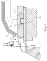
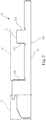
FIGS. 1 and2 , aconventional sinker 10 on a knitting machine generally can be moved reciprocally to-and- fro by driving anub 11 formed thereon. When thesinker 10 is in operation reciprocally for a prolonged period of time, other portions of thesinker 11 such as thepush friction end 101, firstdriving friction end 111, seconddriving friction end 112 andloading friction end 121 have to be properly cooled and lubricated. The most common approach at present is applying lubrication oil. In practice thesinker 10 includes anoil sprinkling zone 14 to receivelubrication oil 71 sprinkled from anoil ejection nozzle 70, and thelubrication oil 71 flows downward after sprinkling to cool and lubricate thepush friction end 101, firstdriving friction end 111, seconddriving friction end 112 andloading friction end 121. However, because the design and structure of theconventional sinker 10 often do not take into account of the lubrication oil could flow to the knittingportion 13, yarns in the knittingportion 13 could be smeared by the lubrication oil during knitting operation and result in increasing of quality defects of the knitting fabrics. - To remedy the aforesaid problem Taiwan patent No.
M365935 - In view of the shortcomings of the conventional sinker how to provide improvement of the sinker to fully and effectively separate the lubrication oil from the yarns or their knitting fabrics is an issue remained to be resolved in the industry.
-
DE 33 25 103 A1 discloses a holding-down sinker for knitting machines which is equipped, in its front part guided in a groove, with a bearing region limited on both sides by sharp-edged steps and coordinated in its length with the length of the guide groove and with the stroke length of the holding-down sinker. Its control foot located in the middle region is connected, via narrow connecting webs formed by lower and upper edge recesses, respectively to the front sinker part and the rear sinker part, which impart elasticity to the control foot in the stroke direction of the holding-down sinker. -
GB 2 134 142 A -
US 841 678 A discloses a groove-guided and reciprocated knitting-machine member having, its rear face, notches separated by a distance less than the extent of reciprocation of said member for engaging and progressively moving foreign matter in the bottom of the groove. - The primary object of the present invention is to solve the shortcomings and problems of the conventional technique by providing a solution that can fully and effectively separate lubrication oil from yarns or knitting fabrics thereof to improve fabric quality to meet industry and market requirements.
- To achieve the foregoing object the present invention provides a sinker equipped with lubrication oil channeling and separating structure. The sinker is a knitting element used on a knitting machine. The knitting machine includes at least a dial, a sinker disc, an oil ejection nozzle located above the sinker disc and a yarn feeder located above the dial and the sinker disc. The dial includes a plurality of needle troughs to hold respectively a knitting needle. The sinker disc includes a plurality of sinker troughs corresponding to the needle troughs to hold the sinker. The sinker includes a base slidable in the sinker troughs and generating friction therewith, a driving nub located above the base, a knitting portion located at a front end of the base, an oil sprinkling zone interposed between the base and the knitting portion corresponding to the oil ejection nozzle. The sinker is characterized in that a lubrication oil channeling and separating structure is interposed between the knitting portion and the oil sprinkling zone. The lubrication oil channeling and separating structure includes a separating slot formed upward from a lower side, a flow channeling portion around the separating slot and close to the oil sprinkling zone, and an oil blocking portion around the separating slot and close to the knitting portion. The lubrication oil channeling and separating structure further includes a jutting debris push portion around the separating slot and below the flow channeling portion, wherein the oil blocking portion is interposed between the separating slot and the knitting portion, and locatable outside the sinker trough while the sinker is fully withdrawn or pushed out on the sinker ring.
- In another aspect when the sinker has fully finished withdrawing movement on the sinker disc the debris push portion is fully withdrawn inside the sinker trough, and when the sinker has been fully pushed out from the sinker disc the debris push portion is exposed outside the sinker trough. According to the invention, the flow channeling portion is inclined from a top end thereof downward towards the oil blocking portion. Further, according to the invention, the oil blocking portion is interposed between the separating slot and the knitting portion, and when the sinker has fully finished withdrawing or push out movement the oil blocking portion is located outside the sinker trough.
- The invention, through the construction set forth above, compared with the conventional techniques, can provide many advantages, such as: the flow channeling portion, the debris push portion and the oil blocking portion are formed around the separating slot that provide respectively different functions of flow channeling, debris pushing and oil blocking, hence the flow channeling portion and the oil blocking portion not only can fully separate lubrication oil from yarns or the knitting fabrics thereof, the debris push portion can also push out cotton debris sunk into the sinker troughs during knitting operation to improve sliding smoothness of the sinker in the sinker troughs, thereby can improve the quality of the knitting fabrics to meet industry and market requirements.
- The foregoing, as well as additional objects, features and advantages of the invention will be more readily apparent from the following detailed description, which proceeds with reference to the accompanying drawings.
-
-
FIG. 1 is a fragmentary sectional view of a conventional sinker located in a knitting machine. -
FIG. 2 is a plane view of the conventional sinker according toFIG. 1 . -
FIG. 3 is a fragmentary enlarged perspective view of an embodiment of the invention. -
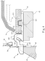
FIG. 4 is a fragmentary sectional view according toFIG. 3 . -
FIG. 5 is a plane view of the sinker according toFIG. 4 . -
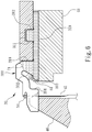
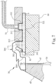
FIGS. 6 through 8 are schematic views of continuous operation conditions of the invention according toFIG. 4 . - As shown in
FIGS. 3 through 5 , the present invention aims to provide a sinker equipped with lubrication oil channeling and separating structure. Thesinker 30 is a knitting element used in aknitting machine 20. Theknitting machine 20 includes at least acylinder 40, asinker ring 60, anoil ejection nozzle 70 located above thesinker ring 60 to sprinklelubrication oil 71 and ayarn feeder 80 located above thecylinder 40 and thesinker ring 60. The cylinder (40) includes a plurality ofneedle troughs 41 to hold respectively a knittingneedle 50. Thesinker ring 60 has a plurality ofsinker troughs 61 corresponding to theneedle troughs 41 to hold thesinker 30. Thesinker 30 includes abase 32 slidable in thesinker troughs 61 to generate friction therewith, a drivingnub 31 located above thebase 32, a knittingportion 33 located at a front end of thebase 32, and anoil sprinkling zone 34 interposed between thebase 32 and theknitting portion 33 corresponding to theoil ejection nozzle 70. While thesinker 30 is driven mainly four frictional portions are generated, including a push-outfriction end 310, a firstdriving friction end 311, a seconddriving friction end 312 and aloading friction end 321. Theoil ejection nozzle 70 is directly located above the oil sprinklingzone 34 so that thelubrication oil 71 can enhance lubrication and cooling through the oil sprinklingzone 34 to the push-outfriction end 310, the firstdriving friction end 311, the seconddriving friction end 312 and theloading friction end 321. It is to be noted that the invention also includes a lubrication oil channeling and separatingstructure 300 interposed between the knittingportion 33 and theoil sprinkling zone 34. The lubrication oil channeling and separatingstructure 300 includes a separatingslot 301 formed upward from a lower side, aflow channeling portion 302 at the separatingslot 301 and close to theoil sprinkling zone 34, and anoil blocking portion 304 at the separatingslot 301 and close to the knittingportion 33. It is also to be noted that the lubrication oil channeling and separatingstructure 300 further includes a juttingdebris push portion 303 located at the separatingslot 301 below theflow channeling portion 302. When thesinker 30 has fully finished withdrawing movement on thesinker disc 60 thedebris push portion 303 is fully withdrawn inside thesinker trough 61, and when thesinker 30 has been fully pushed out from thesinker disc 60 thedebris push portion 303 is exposed outside thesinker trough 61. Moreover, theflow channeling portion 302 is inclined from a top end downward towards theoil blocking portion 304. Theoil blocking portion 304 is interposed between theseparating slot 301 and theknitting portion 33, and when thesinker 30 has fully finished withdrawing or push out movement theoil blocking portion 304 is located outside thesinker trough 61. - As shown in
FIGS. 4 through 8 , when the invention is in use, thesinker 30 can be driven, and the drivingnub 31 is driven to allow thesinker 30 to be fully pushed out from thesinker ring 60 beneath theoil ejection nozzle 70, while theoil ejection nozzle 70 continuously sprinkles thelubrication oil 71 the oil sprinklingzone 34 receive sprinkling of thelubrication oil 71 which starts to flow downward to thebase 32 as shown inFIG. 4 . When thesinker 30 is driven continuously and swivels to start withdrawing movement it also moves away from where theoil ejection nozzle 70 sprinkles thelubrication oil 71, hence although theoil ejection nozzle 70 continuously sprinkles thelubrication oil 71 theoil sprinkling zone 34 of thesinker 30 does not receive sprinkling of thelubrication oil 71, while thelubrication oil 71 received previously flows naturally toward thebase 32 and enters thesinker trough 61 as shown in -
FIG. 6 . Finally, when thesinker 30 is driven and swivels and is fully withdrawn, most of thelubrication oil 71 on thesinker 30 has flown into thesinker trough 61 between thesinker trough 61 and thebase 32, thereby can serve as a medium to cool temperature and perform lubrication between thesinker trough 61 and thebase 32; meanwhile, the distal end of the base 32 also can push debris dropped into thesinker trough 61 outward as shown inFIG. 7 . It is to be noted that, as shown inFIG. 7 , while thelubrication oil 71 flows along a path from thesinker 30 toward the base 32 into thesinker trough 61 the swivelingsinker 30 in the withdrawing process generates a centrifugal force to cause deviation of the flowing path of thelubrication oil 71 that might otherwise flowing directly downward. Thus, with the lubrication oil channeling and separatingstructure 300 formed on thesinker 30 theflow channeling portion 302 at the separatingslot 301 can accelerate flowing downward of thelubrication oil 71, and since theoil blocking portion 304 is located on an outer side of thesinker trough 61 during fully withdrawing of thesinker 30 thelubrication oil 71 cannot pass over the separatingslot 301. As a result, flowing of thelubrication oil 71 to theknitting portion 33 can be averted. It is to be noted that after thesinker 30 is driven and swivels to be pushed outward again the juttingdebris push portion 303 around the separatingslot 301 below theflow channeling portion 302 pushes the debris dropped into thesinker trough 61 outside as shown inFIG. 8 . - In summary there is disclosed a sinker being equipped with lubrication oil channeling and separating structure and being formed to serve a knitting element of a knitting machine which includes at least a
cylinder 40, asinker ring 60, anoil ejection nozzle 70 to sprinklelubrication oil 71 and ayarn feeder 80. Thecylinder 40 includes a plurality ofneedle troughs 41 to hold respectively aknitting needle 50. Thesinker ring 60 includes a plurality ofsinker troughs 61 corresponding to theneedle troughs 41 to hold thesinker 30. Thesinker 30 includes a base 32 located in thesinker troughs 61, a drivingnub 31 located above thebase 32, aknitting portion 33 located at a front end of thebase 32, anoil sprinkling zone 34 interposed between the base 32 and theknitting portion 33 corresponding to theoil ejection nozzle 70, and a lubrication oil channeling and separatingstructure 300 interposed between theknitting portion 33 and theoil sprinkling zone 34. The lubrication oil channeling and separatingstructure 300 includes aseparating slot 301, a flow channeling portion 302 a jutting debris push portion (303), and anoil blocking portion 304 that are at the separatingslot 301, wherein the the oil blocking portion is located outside the sinker trough (61) while the sinker (30) is fully withdrawn or pushed out on the sinker ring (60), and wherein the flow channeling portion (302) is inclined downward from a top end of the flpow channeling portion (302) toward the oil blocking portion (304), the sinker
thus can fully achieve separation effect to improve quality of knitting fabrics to meet industry and market requirements. - As a conclusion, the sinker of the invention includes the lubrication oil channeling and separating structure which includes the flow channeling portion, the debris push portion and the oil blocking portion formed around the separating slot, and the flow channeling portion, the debris push portion and the oil blocking portion can provide various functions such as accelerating flow directing and downward of the lubrication oil, push out of the debris dropped into the sinker trough, and also block the lubrication oil from flowing to the knitting portion. As a result, the flow channeling portion and the oil blocking portion not only can fully separate the lubrication oil the yarns or their fabrics, the debris push portion also can push the debris dropped into the sinker trough during knitting operation to improve sliding smoothness of the sinker in the sinker trough, thereby enhance fabric quality to better meet industry and market requirements.
Claims (2)
- A sinker equipped with a lubrication oil channeling and separating structure and formed to serve as an element of a knitting machine which includes at least a cylinder (40), a sinker ring (60), an oil ejection nozzle (70) located above the sinker ring (60) and a yarn feeder (80) located above the cylinder (40) and the sinker ring (60), the cylinder (40) including a plurality of needle troughs (41) to hold respectively a knitting needle (50), the sinker ring (60) including a plurality of sinker troughs (61) corresponding to the needle troughs (41) to hold the sinker (30), the sinker (30) including:a base (32) slidable in the sinker troughs (61) to generate friction therewith,a driving nub (31) located above the base (32);a knitting portion (33) located at a front end of the base (32); andan oil sprinkling zone (34) interposed between the base (32) and the knitting portion (33) placeable in a position corresponding to the oil ejection nozzle (70); wherein the sinker (30) comprises a lubrication oil channeling and separating structure (300) is interposed between the knitting portion (33) and the oil sprinkling zone (34), and the lubrication oil channeling and separating structure (300) includes a separating slot (301) formed upward from a lower side, a flow channeling portion (302) at the separating slot (301) and close to the oil sprinkling zone (34), an oil blocking portion (304) at the separating slot (301) and close to the knitting portion (33), and a jutting debris push portion (303) at the separating slot (301) and below the flow channeling portion (302), wherein the oil blocking portion (304) is interposed between the separating slot (301) and the knitting portion (33), and locatable outside the sinker trough (61) while the sinker (30) is fully withdrawn or pushed out on the sinker ring (60), the sinker being characterised in that the flow channeling portion (302) is inclined downward from a top end of the flow channeling portion (302) toward the oil blocking portion (304).
- The sinker equipped with lubrication oil channeling and separating structure of claim 1, wherein the debris push portion (303) is fully withdrawnable into the sinker trough (61) while the sinker (30) is fully withdrawn on the sinker ring (60) and exposable outside the sinker trough (61) while the sinker (30) is being fully pushed outside the sinker ring (60).
Priority Applications (1)
| Application Number | Priority Date | Filing Date | Title |
|---|---|---|---|
| EP15193335.5A EP3165650B1 (en) | 2015-11-06 | 2015-11-06 | Sinker equipped with lubrication oil channeling and separating structure |
Applications Claiming Priority (1)
| Application Number | Priority Date | Filing Date | Title |
|---|---|---|---|
| EP15193335.5A EP3165650B1 (en) | 2015-11-06 | 2015-11-06 | Sinker equipped with lubrication oil channeling and separating structure |
Publications (2)
| Publication Number | Publication Date |
|---|---|
| EP3165650A1 EP3165650A1 (en) | 2017-05-10 |
| EP3165650B1 true EP3165650B1 (en) | 2020-07-08 |
Family
ID=54477892
Family Applications (1)
| Application Number | Title | Priority Date | Filing Date |
|---|---|---|---|
| EP15193335.5A Active EP3165650B1 (en) | 2015-11-06 | 2015-11-06 | Sinker equipped with lubrication oil channeling and separating structure |
Country Status (1)
| Country | Link |
|---|---|
| EP (1) | EP3165650B1 (en) |
Family Cites Families (5)
| Publication number | Priority date | Publication date | Assignee | Title |
|---|---|---|---|---|
| US841678A (en) * | 1906-05-22 | 1907-01-22 | Julius Hirsh | Knitting-machine needle. |
| JPS59117691U (en) * | 1983-01-27 | 1984-08-08 | 株式会社福原精機製作所 | sinker for knitting machine |
| DE3325103A1 (en) * | 1983-07-12 | 1985-01-31 | SIPRA Patententwicklungs- und Beteiligungsgesellschaft mbH, 7470 Albstadt | Holding-down sinker for knitting machines |
| JP2900146B2 (en) * | 1995-10-18 | 1999-06-02 | 晴生 山本 | Sinker plate |
| TWM365935U (en) | 2009-05-18 | 2009-10-01 | Shi-Xian Chen | Improved structure of sinker |
-
2015
- 2015-11-06 EP EP15193335.5A patent/EP3165650B1/en active Active
Non-Patent Citations (1)
| Title |
|---|
| None * |
Also Published As
| Publication number | Publication date |
|---|---|
| EP3165650A1 (en) | 2017-05-10 |
Similar Documents
| Publication | Publication Date | Title |
|---|---|---|
| WO2019178999A1 (en) | Flat knitting machine | |
| KR100627534B1 (en) | Gear for knitting machine | |
| KR102921744B1 (en) | Stitch forming elements and stitch forming textile machines | |
| US9617667B1 (en) | Sinker equipped with lubrication oil channeling and separating structure | |
| EP3165650A1 (en) | Sinker equipped with lubrication oil channeling and separating structure | |
| US4574596A (en) | Stitch-forming machine | |
| JPS59144658A (en) | Traverse knitting machine | |
| US3500661A (en) | Method and apparatus for lubricating needle cylinders in circular-knitting machines | |
| CN101096797B (en) | Oil supplying mechanism for flat knitting machine | |
| EP2392710B1 (en) | Flat knitting machine | |
| KR102697548B1 (en) | Circular knitting machine structure | |
| US2475170A (en) | Knitting machine cam race | |
| CN215800231U (en) | Knitting and yarn pressing mechanism of glove knitting machine | |
| EP0567880A2 (en) | Circular knitting machine for manufacturing socks, stockings or the like, with an improved knitting forming cam set | |
| US3499300A (en) | Pattern device for circular knitting machines | |
| US3751943A (en) | Apparatus for controlling the jacks and needles of circular knitting machines | |
| CN109056178B (en) | Sheeting in flat knitting machine | |
| JP7499792B2 (en) | Method and machine for plating with compound needles on a circular knitting machine | |
| CN113622076A (en) | Knitting and yarn pressing mechanism of glove knitting machine | |
| US2741519A (en) | Piston engine | |
| CN209211042U (en) | A kind of knitting needle for knitting machine | |
| CN106676739B (en) | Sinker with lubricating oil flow guide and separation structure | |
| US8371144B1 (en) | Loop forming and loosening mechanism and sinkers thereof for circular knitting machines | |
| TW201715113A (en) | Sinker equipped with lubrication oil channeling and separating structure | |
| CN216040171U (en) | Feeding adjusting screw |
Legal Events
| Date | Code | Title | Description |
|---|---|---|---|
| PUAI | Public reference made under article 153(3) epc to a published international application that has entered the european phase |
Free format text: ORIGINAL CODE: 0009012 |
|
| STAA | Information on the status of an ep patent application or granted ep patent |
Free format text: STATUS: REQUEST FOR EXAMINATION WAS MADE |
|
| 17P | Request for examination filed |
Effective date: 20161025 |
|
| AK | Designated contracting states |
Kind code of ref document: A1 Designated state(s): AL AT BE BG CH CY CZ DE DK EE ES FI FR GB GR HR HU IE IS IT LI LT LU LV MC MK MT NL NO PL PT RO RS SE SI SK SM TR |
|
| AX | Request for extension of the european patent |
Extension state: BA ME |
|
| STAA | Information on the status of an ep patent application or granted ep patent |
Free format text: STATUS: EXAMINATION IS IN PROGRESS |
|
| 17Q | First examination report despatched |
Effective date: 20190104 |
|
| GRAP | Despatch of communication of intention to grant a patent |
Free format text: ORIGINAL CODE: EPIDOSNIGR1 |
|
| STAA | Information on the status of an ep patent application or granted ep patent |
Free format text: STATUS: GRANT OF PATENT IS INTENDED |
|
| INTG | Intention to grant announced |
Effective date: 20200331 |
|
| GRAS | Grant fee paid |
Free format text: ORIGINAL CODE: EPIDOSNIGR3 |
|
| GRAA | (expected) grant |
Free format text: ORIGINAL CODE: 0009210 |
|
| STAA | Information on the status of an ep patent application or granted ep patent |
Free format text: STATUS: THE PATENT HAS BEEN GRANTED |
|
| AK | Designated contracting states |
Kind code of ref document: B1 Designated state(s): AL AT BE BG CH CY CZ DE DK EE ES FI FR GB GR HR HU IE IS IT LI LT LU LV MC MK MT NL NO PL PT RO RS SE SI SK SM TR |
|
| REG | Reference to a national code |
Ref country code: CH Ref legal event code: EP Ref country code: AT Ref legal event code: REF Ref document number: 1288542 Country of ref document: AT Kind code of ref document: T Effective date: 20200715 |
|
| REG | Reference to a national code |
Ref country code: DE Ref legal event code: R096 Ref document number: 602015055335 Country of ref document: DE |
|
| REG | Reference to a national code |
Ref country code: IE Ref legal event code: FG4D |
|
| REG | Reference to a national code |
Ref country code: LT Ref legal event code: MG4D |
|
| REG | Reference to a national code |
Ref country code: AT Ref legal event code: MK05 Ref document number: 1288542 Country of ref document: AT Kind code of ref document: T Effective date: 20200708 |
|
| REG | Reference to a national code |
Ref country code: NL Ref legal event code: MP Effective date: 20200708 |
|
| PG25 | Lapsed in a contracting state [announced via postgrant information from national office to epo] |
Ref country code: FI Free format text: LAPSE BECAUSE OF FAILURE TO SUBMIT A TRANSLATION OF THE DESCRIPTION OR TO PAY THE FEE WITHIN THE PRESCRIBED TIME-LIMIT Effective date: 20200708 Ref country code: PT Free format text: LAPSE BECAUSE OF FAILURE TO SUBMIT A TRANSLATION OF THE DESCRIPTION OR TO PAY THE FEE WITHIN THE PRESCRIBED TIME-LIMIT Effective date: 20201109 Ref country code: HR Free format text: LAPSE BECAUSE OF FAILURE TO SUBMIT A TRANSLATION OF THE DESCRIPTION OR TO PAY THE FEE WITHIN THE PRESCRIBED TIME-LIMIT Effective date: 20200708 Ref country code: LT Free format text: LAPSE BECAUSE OF FAILURE TO SUBMIT A TRANSLATION OF THE DESCRIPTION OR TO PAY THE FEE WITHIN THE PRESCRIBED TIME-LIMIT Effective date: 20200708 Ref country code: ES Free format text: LAPSE BECAUSE OF FAILURE TO SUBMIT A TRANSLATION OF THE DESCRIPTION OR TO PAY THE FEE WITHIN THE PRESCRIBED TIME-LIMIT Effective date: 20200708 Ref country code: SE Free format text: LAPSE BECAUSE OF FAILURE TO SUBMIT A TRANSLATION OF THE DESCRIPTION OR TO PAY THE FEE WITHIN THE PRESCRIBED TIME-LIMIT Effective date: 20200708 Ref country code: BG Free format text: LAPSE BECAUSE OF FAILURE TO SUBMIT A TRANSLATION OF THE DESCRIPTION OR TO PAY THE FEE WITHIN THE PRESCRIBED TIME-LIMIT Effective date: 20201008 Ref country code: AT Free format text: LAPSE BECAUSE OF FAILURE TO SUBMIT A TRANSLATION OF THE DESCRIPTION OR TO PAY THE FEE WITHIN THE PRESCRIBED TIME-LIMIT Effective date: 20200708 Ref country code: GR Free format text: LAPSE BECAUSE OF FAILURE TO SUBMIT A TRANSLATION OF THE DESCRIPTION OR TO PAY THE FEE WITHIN THE PRESCRIBED TIME-LIMIT Effective date: 20201009 Ref country code: NO Free format text: LAPSE BECAUSE OF FAILURE TO SUBMIT A TRANSLATION OF THE DESCRIPTION OR TO PAY THE FEE WITHIN THE PRESCRIBED TIME-LIMIT Effective date: 20201008 |
|
| PG25 | Lapsed in a contracting state [announced via postgrant information from national office to epo] |
Ref country code: PL Free format text: LAPSE BECAUSE OF FAILURE TO SUBMIT A TRANSLATION OF THE DESCRIPTION OR TO PAY THE FEE WITHIN THE PRESCRIBED TIME-LIMIT Effective date: 20200708 Ref country code: RS Free format text: LAPSE BECAUSE OF FAILURE TO SUBMIT A TRANSLATION OF THE DESCRIPTION OR TO PAY THE FEE WITHIN THE PRESCRIBED TIME-LIMIT Effective date: 20200708 Ref country code: LV Free format text: LAPSE BECAUSE OF FAILURE TO SUBMIT A TRANSLATION OF THE DESCRIPTION OR TO PAY THE FEE WITHIN THE PRESCRIBED TIME-LIMIT Effective date: 20200708 Ref country code: IS Free format text: LAPSE BECAUSE OF FAILURE TO SUBMIT A TRANSLATION OF THE DESCRIPTION OR TO PAY THE FEE WITHIN THE PRESCRIBED TIME-LIMIT Effective date: 20201108 |
|
| PG25 | Lapsed in a contracting state [announced via postgrant information from national office to epo] |
Ref country code: NL Free format text: LAPSE BECAUSE OF FAILURE TO SUBMIT A TRANSLATION OF THE DESCRIPTION OR TO PAY THE FEE WITHIN THE PRESCRIBED TIME-LIMIT Effective date: 20200708 |
|
| REG | Reference to a national code |
Ref country code: DE Ref legal event code: R097 Ref document number: 602015055335 Country of ref document: DE |
|
| PG25 | Lapsed in a contracting state [announced via postgrant information from national office to epo] |
Ref country code: EE Free format text: LAPSE BECAUSE OF FAILURE TO SUBMIT A TRANSLATION OF THE DESCRIPTION OR TO PAY THE FEE WITHIN THE PRESCRIBED TIME-LIMIT Effective date: 20200708 Ref country code: SM Free format text: LAPSE BECAUSE OF FAILURE TO SUBMIT A TRANSLATION OF THE DESCRIPTION OR TO PAY THE FEE WITHIN THE PRESCRIBED TIME-LIMIT Effective date: 20200708 Ref country code: RO Free format text: LAPSE BECAUSE OF FAILURE TO SUBMIT A TRANSLATION OF THE DESCRIPTION OR TO PAY THE FEE WITHIN THE PRESCRIBED TIME-LIMIT Effective date: 20200708 Ref country code: DK Free format text: LAPSE BECAUSE OF FAILURE TO SUBMIT A TRANSLATION OF THE DESCRIPTION OR TO PAY THE FEE WITHIN THE PRESCRIBED TIME-LIMIT Effective date: 20200708 |
|
| PLBE | No opposition filed within time limit |
Free format text: ORIGINAL CODE: 0009261 |
|
| STAA | Information on the status of an ep patent application or granted ep patent |
Free format text: STATUS: NO OPPOSITION FILED WITHIN TIME LIMIT |
|
| PG25 | Lapsed in a contracting state [announced via postgrant information from national office to epo] |
Ref country code: AL Free format text: LAPSE BECAUSE OF FAILURE TO SUBMIT A TRANSLATION OF THE DESCRIPTION OR TO PAY THE FEE WITHIN THE PRESCRIBED TIME-LIMIT Effective date: 20200708 |
|
| 26N | No opposition filed |
Effective date: 20210409 |
|
| PG25 | Lapsed in a contracting state [announced via postgrant information from national office to epo] |
Ref country code: MC Free format text: LAPSE BECAUSE OF FAILURE TO SUBMIT A TRANSLATION OF THE DESCRIPTION OR TO PAY THE FEE WITHIN THE PRESCRIBED TIME-LIMIT Effective date: 20200708 Ref country code: SK Free format text: LAPSE BECAUSE OF FAILURE TO SUBMIT A TRANSLATION OF THE DESCRIPTION OR TO PAY THE FEE WITHIN THE PRESCRIBED TIME-LIMIT Effective date: 20200708 |
|
| REG | Reference to a national code |
Ref country code: CH Ref legal event code: PL |
|
| GBPC | Gb: european patent ceased through non-payment of renewal fee |
Effective date: 20201106 |
|
| PG25 | Lapsed in a contracting state [announced via postgrant information from national office to epo] |
Ref country code: LU Free format text: LAPSE BECAUSE OF NON-PAYMENT OF DUE FEES Effective date: 20201106 |
|
| REG | Reference to a national code |
Ref country code: BE Ref legal event code: MM Effective date: 20201130 |
|
| PG25 | Lapsed in a contracting state [announced via postgrant information from national office to epo] |
Ref country code: SI Free format text: LAPSE BECAUSE OF FAILURE TO SUBMIT A TRANSLATION OF THE DESCRIPTION OR TO PAY THE FEE WITHIN THE PRESCRIBED TIME-LIMIT Effective date: 20200708 Ref country code: LI Free format text: LAPSE BECAUSE OF NON-PAYMENT OF DUE FEES Effective date: 20201130 Ref country code: CH Free format text: LAPSE BECAUSE OF NON-PAYMENT OF DUE FEES Effective date: 20201130 |
|
| PG25 | Lapsed in a contracting state [announced via postgrant information from national office to epo] |
Ref country code: FR Free format text: LAPSE BECAUSE OF NON-PAYMENT OF DUE FEES Effective date: 20201130 Ref country code: IE Free format text: LAPSE BECAUSE OF NON-PAYMENT OF DUE FEES Effective date: 20201106 |
|
| PG25 | Lapsed in a contracting state [announced via postgrant information from national office to epo] |
Ref country code: GB Free format text: LAPSE BECAUSE OF NON-PAYMENT OF DUE FEES Effective date: 20201106 |
|
| PG25 | Lapsed in a contracting state [announced via postgrant information from national office to epo] |
Ref country code: IS Free format text: LAPSE BECAUSE OF FAILURE TO SUBMIT A TRANSLATION OF THE DESCRIPTION OR TO PAY THE FEE WITHIN THE PRESCRIBED TIME-LIMIT Effective date: 20201108 Ref country code: MT Free format text: LAPSE BECAUSE OF FAILURE TO SUBMIT A TRANSLATION OF THE DESCRIPTION OR TO PAY THE FEE WITHIN THE PRESCRIBED TIME-LIMIT Effective date: 20200708 Ref country code: CY Free format text: LAPSE BECAUSE OF FAILURE TO SUBMIT A TRANSLATION OF THE DESCRIPTION OR TO PAY THE FEE WITHIN THE PRESCRIBED TIME-LIMIT Effective date: 20200708 |
|
| PG25 | Lapsed in a contracting state [announced via postgrant information from national office to epo] |
Ref country code: MK Free format text: LAPSE BECAUSE OF FAILURE TO SUBMIT A TRANSLATION OF THE DESCRIPTION OR TO PAY THE FEE WITHIN THE PRESCRIBED TIME-LIMIT Effective date: 20200708 |
|
| PG25 | Lapsed in a contracting state [announced via postgrant information from national office to epo] |
Ref country code: BE Free format text: LAPSE BECAUSE OF NON-PAYMENT OF DUE FEES Effective date: 20201130 |
|
| PGFP | Annual fee paid to national office [announced via postgrant information from national office to epo] |
Ref country code: TR Payment date: 20221101 Year of fee payment: 8 Ref country code: IT Payment date: 20221130 Year of fee payment: 8 Ref country code: CZ Payment date: 20221026 Year of fee payment: 8 |
|
| PGFP | Annual fee paid to national office [announced via postgrant information from national office to epo] |
Ref country code: DE Payment date: 20221130 Year of fee payment: 8 |
|
| P01 | Opt-out of the competence of the unified patent court (upc) registered |
Effective date: 20230523 |
|
| REG | Reference to a national code |
Ref country code: DE Ref legal event code: R119 Ref document number: 602015055335 Country of ref document: DE |
|
| PG25 | Lapsed in a contracting state [announced via postgrant information from national office to epo] |
Ref country code: CZ Free format text: LAPSE BECAUSE OF NON-PAYMENT OF DUE FEES Effective date: 20231106 |
|
| PG25 | Lapsed in a contracting state [announced via postgrant information from national office to epo] |
Ref country code: CZ Free format text: LAPSE BECAUSE OF NON-PAYMENT OF DUE FEES Effective date: 20231106 |
|
| PG25 | Lapsed in a contracting state [announced via postgrant information from national office to epo] |
Ref country code: DE Free format text: LAPSE BECAUSE OF NON-PAYMENT OF DUE FEES Effective date: 20240601 |
|
| PG25 | Lapsed in a contracting state [announced via postgrant information from national office to epo] |
Ref country code: DE Free format text: LAPSE BECAUSE OF NON-PAYMENT OF DUE FEES Effective date: 20240601 |
|
| PG25 | Lapsed in a contracting state [announced via postgrant information from national office to epo] |
Ref country code: IT Free format text: LAPSE BECAUSE OF NON-PAYMENT OF DUE FEES Effective date: 20231106 |
|
| PG25 | Lapsed in a contracting state [announced via postgrant information from national office to epo] |
Ref country code: IT Free format text: LAPSE BECAUSE OF NON-PAYMENT OF DUE FEES Effective date: 20231106 |