EP3165458B1 - Faucet for water supply unit for aircraft - Google Patents
Faucet for water supply unit for aircraft Download PDFInfo
- Publication number
- EP3165458B1 EP3165458B1 EP14896445.5A EP14896445A EP3165458B1 EP 3165458 B1 EP3165458 B1 EP 3165458B1 EP 14896445 A EP14896445 A EP 14896445A EP 3165458 B1 EP3165458 B1 EP 3165458B1
- Authority
- EP
- European Patent Office
- Prior art keywords
- water
- adapter
- faucet
- aircraft
- body portion
- Prior art date
- Legal status (The legal status is an assumption and is not a legal conclusion. Google has not performed a legal analysis and makes no representation as to the accuracy of the status listed.)
- Not-in-force
Links
Images


Classifications
-
- B—PERFORMING OPERATIONS; TRANSPORTING
- B64—AIRCRAFT; AVIATION; COSMONAUTICS
- B64D—EQUIPMENT FOR FITTING IN OR TO AIRCRAFT; FLIGHT SUITS; PARACHUTES; ARRANGEMENT OR MOUNTING OF POWER PLANTS OR PROPULSION TRANSMISSIONS IN AIRCRAFT
- B64D11/00—Passenger or crew accommodation; Flight-deck installations not otherwise provided for
- B64D11/02—Toilet fittings
-
- B—PERFORMING OPERATIONS; TRANSPORTING
- B64—AIRCRAFT; AVIATION; COSMONAUTICS
- B64D—EQUIPMENT FOR FITTING IN OR TO AIRCRAFT; FLIGHT SUITS; PARACHUTES; ARRANGEMENT OR MOUNTING OF POWER PLANTS OR PROPULSION TRANSMISSIONS IN AIRCRAFT
- B64D11/00—Passenger or crew accommodation; Flight-deck installations not otherwise provided for
- B64D11/04—Galleys
-
- E—FIXED CONSTRUCTIONS
- E03—WATER SUPPLY; SEWERAGE
- E03B—INSTALLATIONS OR METHODS FOR OBTAINING, COLLECTING, OR DISTRIBUTING WATER
- E03B11/00—Arrangements or adaptations of tanks for water supply
- E03B11/02—Arrangements or adaptations of tanks for water supply for domestic or like local water supply
- E03B11/06—Arrangements or adaptations of tanks for water supply for domestic or like local water supply with air regulators
-
- E—FIXED CONSTRUCTIONS
- E03—WATER SUPPLY; SEWERAGE
- E03C—DOMESTIC PLUMBING INSTALLATIONS FOR FRESH WATER OR WASTE WATER; SINKS
- E03C1/00—Domestic plumbing installations for fresh water or waste water; Sinks
- E03C1/02—Plumbing installations for fresh water
- E03C1/04—Water-basin installations specially adapted to wash-basins or baths
- E03C1/0401—Fixing a tap to the sanitary appliance or to an associated mounting surface, e.g. a countertop
-
- E—FIXED CONSTRUCTIONS
- E03—WATER SUPPLY; SEWERAGE
- E03C—DOMESTIC PLUMBING INSTALLATIONS FOR FRESH WATER OR WASTE WATER; SINKS
- E03C1/00—Domestic plumbing installations for fresh water or waste water; Sinks
- E03C1/02—Plumbing installations for fresh water
- E03C1/08—Jet regulators or jet guides, e.g. anti-splash devices
- E03C1/084—Jet regulators with aerating means
-
- Y—GENERAL TAGGING OF NEW TECHNOLOGICAL DEVELOPMENTS; GENERAL TAGGING OF CROSS-SECTIONAL TECHNOLOGIES SPANNING OVER SEVERAL SECTIONS OF THE IPC; TECHNICAL SUBJECTS COVERED BY FORMER USPC CROSS-REFERENCE ART COLLECTIONS [XRACs] AND DIGESTS
- Y02—TECHNOLOGIES OR APPLICATIONS FOR MITIGATION OR ADAPTATION AGAINST CLIMATE CHANGE
- Y02T—CLIMATE CHANGE MITIGATION TECHNOLOGIES RELATED TO TRANSPORTATION
- Y02T50/00—Aeronautics or air transport
- Y02T50/40—Weight reduction
Definitions
- the present invention relates to a faucet, or water tap, used in a water supply unit provided in a lavatory, or washroom, a galley, or kitchen, and so on mounted on a passenger aircraft.
- a water supply unit 100 provided in a lavatory for an aircraft mounted on a passenger aircraft includes, for example as illustrated in FIG. 5 , a water supply line 102 connected to a hydrant 101, a hot water supply line 103 diverged from the water supply line 102 and connected to the hydrant 101, a water heater 104 arranged in midway of the hot water supply line 103, and a faucet 105 mounted to the hydrant 101.
- a plurality of facilities that use water such as lavatories and galleys, are provided in a passenger aircraft.
- one known measure for saving the amount of discharged water is a method of attaching a water saving piece having a bubble forming implement and two layers of orifice members arranged upstream of the bubble forming implement built into a casing to a water tap of water supplied to households (refer for example to Patent Literature 1).
- Patent Literature 1 It is disclosed in Patent Literature 1 that a water tap adopting the water saving piece of Patent Literature 1 realizes a high water saving effect and enables to form bubbles stably even in a flow rate of 5 L/min, by selecting an appropriate combination of the shapes of the orifice members arranged in two layers within the casing.
- Patent Literature 1 not enough supply of water can be acquired by merely attaching the water saving piece taught in Patent Literature 1 is merely attached to the faucet of the water supply system of an aircraft, so that there was a drawback that it was not possible to realize both usability of the water discharged through the faucet and water saving effect.
- Document US 2 811 340 discloses a fluid mixing device for mixing a liquid under pressure with atmospheric air.
- the object of the present invention is to provide a faucet capable of discharging water having necessary water pressure and achieving a water saving effect at the same time, even if the flow rate of water is within a small range as in the case of water supplied in an aircraft.
- the present invention provides a faucet for a water supply system for an aircraft according to claim 1.
- the adapter includes a metal cap member having a plurality of holes on a side of the casing opposite from a side mounted to the body portion.
- the adapter can further include a strainer on a side of the casing mounted to the body portion.
- the faucet for a water supply unit for an aircraft can be applied to a lavatory unit for an aircraft or a galley for an aircraft.
- FIG. 1 illustrates a configuration of a faucet for a water supply unit for an aircraft according to the present invention.
- a faucet 10 is composed of a body portion 11, and an adapter 12 mounted to a discharge portion of the body portion 11.
- the body portion 11 is mounted to a washbasin of a lavatory or a sink of a galley provided in an aircraft, and a water passage is formed within the body portion 11 and connected to a hydrant.
- FIG. 2 is a view illustrating an inner structure of the adapter 12 illustrated in FIG. 1 .
- the adapter 12 adopts a structure where a mounting member 20 for mounting to the faucet 10 and an adapter body portion 22 are screw-engaged to form a casing, and an orifice 21 is formed at a center portion of the mounting member 20.
- a portion upstream of the orifice 21 in the mounting member 20 is designed to have a diameter gradually narrowed down from an opening. Such shape facilitates the processing of the mounting member 20.
- the shape of the portion upstream of the orifice 21 is not restricted to a shape having a gradually narrowing diameter, and can adopt other shapes such as a stepped shape.
- the mounting member 20 includes a negative pressure forming chamber 20a communicated with the orifice 21, and an air passage hole 20b communicated from the negative pressure forming chamber 20a to an exterior of the mounting member 20.
- an opening diameter of the negative pressure forming chamber 20a is formed greater than an opening diameter of the orifice 21.
- a partially cut-out clearance is formed at a screw-engaged portion between the mounting member 20 and the adapter body portion 22, and the negative pressure forming chamber 20a adopts a structure to take in outer air through the air passage hole 20b by connecting the clearance with the air passage hole 20b.
- the adapter body portion 22 has, in the interior thereof, a metal cap member 23 having a plurality of holes through which water mixed with air is discharged, and a dispersion member 24 that diverges water having passed through the negative pressure forming chamber 20a into a plurality of water flows and then merges the diverged water flows.
- the dispersion member 24 adopts a configuration where a substantially conical projection 24a is formed at a center portion of one surface, and having a plurality of dispersed holes formed in a circumference of the projection 24a.
- the water having passed through the negative pressure forming chamber 20a of the mounting member 20 is dispersed through the projection 24a from the center portion toward the outer circumferential direction, and the water having passed through the dispersed holes is diverged into a plurality of water flows, before the plurality of diverged flows are merged again.
- a seal packing respectively between the mounting member 20 and the adapter body portion 22, and between the adapter body portion 22 and the metal cap member 23 or the dispersion member 24 received within the adapter body portion 22.
- This configuration enables to prevent leakage of water from the adapter 12, and also prevent foreign substances within the water from entering the adapter 12.
- the water flowing in from the body portion 11 of the faucet 10 passes through the orifice 21 and enters the negative pressure forming chamber 20a, and the water is mixed with the air flowing in through a communication hole 20b within the negative pressure forming chamber 20a.
- the negative pressure forming chamber 20a is set to negative pressure, so that the water will not flow out to the exterior through the communication hole 20b.
- the water flow of water mixed with air having passed through the negative pressure forming chamber 20a is passed through the dispersed holes of the dispersion member 24, diverged into multiple water flows, and then merged again, according to which the air-mixed water flow is further stirred and mixed, before the water finally passes through the metal cap member 23 and discharged as multiple shower flows through the adapter 12.
- the water saving effect can be achieved without changing the feeling of use of water (level of discharge of water from the faucet) with respect to the air-mixed water flow, even with a small amount of water.
- the adapter 12 illustrated above can be mounted to and removed from an existing faucet through screwing, without using any tool, by devising the shape of the mounting member 20.
- FIG. 3 is a graph illustrating a water saving effect by using the faucet 10 according to the present invention.
- FIG. 3 showing a graph where a horizontal axis represents water pressure (MPa) and a vertical axis represents flow rate (L/min), in a case where the faucet according to the present invention denoted by black squares ( ⁇ ) is used, compared to the prior-art type faucet denoted by black circles ( ⁇ ), a flow rate as small as approximately 0.69 L/min is realized in a case where the water pressure is 0.15 MPa, and a flow rate as small as approximately 0.87 L/min is realized in a case where the water pressure is 0.25 MPa, so that a water saving effect of 8 to 32 % can be achieved within such water pressure range.
- MPa water pressure
- L/min flow rate
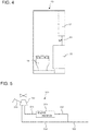
- FIG. 4 is a front view illustrating a specific example of a case where the faucet 10 according to the present invention is applied to a lavatory unit for an aircraft.
- an aircraft lavatory unit 30 has a toilet unit 31, a washbasin unit 32 and a mirror 33 provided within a lavatory space surrounded by a plurality of panels.
- the faucet 10 according to the present invention is provided above the washbasin unit 32, and an amenity storage unit storing amenities such as various expendables is formed in an inner portion of the washbasin unit 32.
- the faucet 10 according to the present invention adopts a simple configuration of merely mounting the adapter 12 to the discharge portion of the body portion 11, as illustrated in FIG. 1 , the adapter 12 can easily be mounted to, or replaced with, the discharge portion of an existing faucet.
- the total amount of water (tank capacity) loaded in the aircraft can be reduced, so that as a result, the weight of the aircraft body during flight as a passenger aircraft can be reduced, which leads to improving fuel efficiency, and enabling to increase the number of passenger seats or increasing the load.
- FIG. 4 illustrates an example where the water supply system including the faucet 10 according to the present invention is applied to a lavatory unit of an aircraft, but the faucet according to the present invention can also be applied, for example, to a water supply system or the like of a sink provided within a galley of an aircraft for serving meals.
Landscapes
- Engineering & Computer Science (AREA)
- Aviation & Aerospace Engineering (AREA)
- Health & Medical Sciences (AREA)
- Life Sciences & Earth Sciences (AREA)
- Hydrology & Water Resources (AREA)
- Public Health (AREA)
- Water Supply & Treatment (AREA)
- Structural Engineering (AREA)
- Domestic Plumbing Installations (AREA)
Description
- The present invention relates to a faucet, or water tap, used in a water supply unit provided in a lavatory, or washroom, a galley, or kitchen, and so on mounted on a passenger aircraft.
- A
water supply unit 100 provided in a lavatory for an aircraft mounted on a passenger aircraft includes, for example as illustrated inFIG. 5 , awater supply line 102 connected to ahydrant 101, a hotwater supply line 103 diverged from thewater supply line 102 and connected to thehydrant 101, awater heater 104 arranged in midway of the hotwater supply line 103, and afaucet 105 mounted to thehydrant 101. - In general, a plurality of facilities that use water, such as lavatories and galleys, are provided in a passenger aircraft.
- However, once water and oil are supplied to the passenger aircraft at an airport, water will not be supplied to the aircraft until the aircraft reaches the airport of the destination, so that the water stored in a tank with a limited capacity is required to be consumed efficiently.
- On the other hand, one known measure for saving the amount of discharged water is a method of attaching a water saving piece having a bubble forming implement and two layers of orifice members arranged upstream of the bubble forming implement built into a casing to a water tap of water supplied to households (refer for example to Patent Literature 1).
- [PTL 1] Japanese Unexamined Patent Application Publication No.
2004-132138 - It is disclosed in
Patent Literature 1 that a water tap adopting the water saving piece ofPatent Literature 1 realizes a high water saving effect and enables to form bubbles stably even in a flow rate of 5 L/min, by selecting an appropriate combination of the shapes of the orifice members arranged in two layers within the casing. - However, in a water supply unit of an aircraft, there is only a limited space for arranging a pump for supplying water, so that it is difficult to use a large-scale pump with a high discharge ability, and as a result, water is supplied within a range (such as 1 L/min) smaller than the flow rate of tap water supplied to normal households.
- Therefore, not enough supply of water can be acquired by merely attaching the water saving piece taught in
Patent Literature 1 is merely attached to the faucet of the water supply system of an aircraft, so that there was a drawback that it was not possible to realize both usability of the water discharged through the faucet and water saving effect. - Document
US 2 811 340 discloses a fluid mixing device for mixing a liquid under pressure with atmospheric air. - Therefore, the object of the present invention is to provide a faucet capable of discharging water having necessary water pressure and achieving a water saving effect at the same time, even if the flow rate of water is within a small range as in the case of water supplied in an aircraft.
- In order to solve the problems described above, the present invention provides a faucet for a water supply system for an aircraft according to
claim 1. - Further, the adapter includes a metal cap member having a plurality of holes on a side of the casing opposite from a side mounted to the body portion.
- The adapter can further include a strainer on a side of the casing mounted to the body portion.
- Further, the faucet for a water supply unit for an aircraft can be applied to a lavatory unit for an aircraft or a galley for an aircraft.
- It becomes possible to discharge water with a necessary water pressure and achieve a water saving effect even in a water with a flow rate of a small range, as in the water supplied within an aircraft, by adopting the faucet for a water supply system for an aircraft according to the present invention.
- Further, since the total amount of water, that is, the capacity of a tank, loaded on the aircraft can be reduced by achieving the above-described water saving effect, effects such as the reduction of weight of the airframe of the passenger aircraft in operation, the contribution to improvement of fuel efficiency, and the increase of number of passenger seats and increase of load can be exerted.
-
-
FIG. 1 is a view illustrating a configuration of a faucet of a water supply system of an aircraft according to the present invention. -
FIG. 2 is a view illustrating an internal configuration of anadapter 12 illustrated inFIG. 1 . -
FIG. 3 is a graph illustrating a water saving effect by using afaucet 10 according to the present invention. -
FIG. 4 is a front view illustrating a specific example having applied thefaucet 10 according to the present invention to a lavatory unit for an aircraft. -
FIG. 5 is a schematic view illustrating one example of a water supply unit adopted in a lavatory for an aircraft disposed in a passenger aircraft. -
FIG. 1 illustrates a configuration of a faucet for a water supply unit for an aircraft according to the present invention. - A
faucet 10 is composed of abody portion 11, and anadapter 12 mounted to a discharge portion of thebody portion 11. - The
body portion 11 is mounted to a washbasin of a lavatory or a sink of a galley provided in an aircraft, and a water passage is formed within thebody portion 11 and connected to a hydrant. -
FIG. 2 is a view illustrating an inner structure of theadapter 12 illustrated inFIG. 1 . - The
adapter 12 adopts a structure where amounting member 20 for mounting to thefaucet 10 and anadapter body portion 22 are screw-engaged to form a casing, and anorifice 21 is formed at a center portion of themounting member 20. - Now, as illustrated in
FIG. 2 , a portion upstream of theorifice 21 in themounting member 20 is designed to have a diameter gradually narrowed down from an opening. Such shape facilitates the processing of themounting member 20. - The shape of the portion upstream of the
orifice 21 is not restricted to a shape having a gradually narrowing diameter, and can adopt other shapes such as a stepped shape. - Further, the
mounting member 20 includes a negativepressure forming chamber 20a communicated with theorifice 21, and anair passage hole 20b communicated from the negativepressure forming chamber 20a to an exterior of themounting member 20. - Now, as illustrated in
FIG. 2 , an opening diameter of the negativepressure forming chamber 20a is formed greater than an opening diameter of theorifice 21. - Further, a partially cut-out clearance is formed at a screw-engaged portion between the
mounting member 20 and theadapter body portion 22, and the negativepressure forming chamber 20a adopts a structure to take in outer air through theair passage hole 20b by connecting the clearance with theair passage hole 20b. - On the other hand, the
adapter body portion 22 has, in the interior thereof, ametal cap member 23 having a plurality of holes through which water mixed with air is discharged, and adispersion member 24 that diverges water having passed through the negativepressure forming chamber 20a into a plurality of water flows and then merges the diverged water flows. - The
dispersion member 24 adopts a configuration where a substantiallyconical projection 24a is formed at a center portion of one surface, and having a plurality of dispersed holes formed in a circumference of theprojection 24a. - According to the above-described configuration of the
dispersion member 24, the water having passed through the negativepressure forming chamber 20a of themounting member 20 is dispersed through theprojection 24a from the center portion toward the outer circumferential direction, and the water having passed through the dispersed holes is diverged into a plurality of water flows, before the plurality of diverged flows are merged again. - It is preferable to arrange a seal packing respectively between the
mounting member 20 and theadapter body portion 22, and between theadapter body portion 22 and themetal cap member 23 or thedispersion member 24 received within theadapter body portion 22. - Further, it is possible to provide a strainer on an upstream side of the
orifice 21 formed on themounting member 20. - This configuration enables to prevent leakage of water from the
adapter 12, and also prevent foreign substances within the water from entering theadapter 12. - According to the
adapter 12 configured as above, the water flowing in from thebody portion 11 of thefaucet 10 passes through theorifice 21 and enters the negativepressure forming chamber 20a, and the water is mixed with the air flowing in through acommunication hole 20b within the negativepressure forming chamber 20a. At this time, the negativepressure forming chamber 20a is set to negative pressure, so that the water will not flow out to the exterior through thecommunication hole 20b. - The water flow of water mixed with air having passed through the negative
pressure forming chamber 20a is passed through the dispersed holes of thedispersion member 24, diverged into multiple water flows, and then merged again, according to which the air-mixed water flow is further stirred and mixed, before the water finally passes through themetal cap member 23 and discharged as multiple shower flows through theadapter 12. - Now, by optimizing diameters or arrangements of discharge holes formed to the
metal cap member 23, the water saving effect can be achieved without changing the feeling of use of water (level of discharge of water from the faucet) with respect to the air-mixed water flow, even with a small amount of water. - Further, the
adapter 12 illustrated above can be mounted to and removed from an existing faucet through screwing, without using any tool, by devising the shape of themounting member 20. -
FIG. 3 is a graph illustrating a water saving effect by using thefaucet 10 according to the present invention. - As illustrated in
FIG. 3 showing a graph where a horizontal axis represents water pressure (MPa) and a vertical axis represents flow rate (L/min), in a case where the faucet according to the present invention denoted by black squares (■) is used, compared to the prior-art type faucet denoted by black circles (●), a flow rate as small as approximately 0.69 L/min is realized in a case where the water pressure is 0.15 MPa, and a flow rate as small as approximately 0.87 L/min is realized in a case where the water pressure is 0.25 MPa, so that a water saving effect of 8 to 32 % can be achieved within such water pressure range. - The use of such faucet realizes sufficient water saving effect while discharging water with necessary water pressure, even if the flow rate is within a small range as in the case of water supplied on an aircraft.
-
FIG. 4 is a front view illustrating a specific example of a case where thefaucet 10 according to the present invention is applied to a lavatory unit for an aircraft. - As illustrated in
FIG. 4 , anaircraft lavatory unit 30 has atoilet unit 31, awashbasin unit 32 and amirror 33 provided within a lavatory space surrounded by a plurality of panels. - The
faucet 10 according to the present invention is provided above thewashbasin unit 32, and an amenity storage unit storing amenities such as various expendables is formed in an inner portion of thewashbasin unit 32. - Since the
faucet 10 according to the present invention adopts a simple configuration of merely mounting theadapter 12 to the discharge portion of thebody portion 11, as illustrated inFIG. 1 , theadapter 12 can easily be mounted to, or replaced with, the discharge portion of an existing faucet. - Further, since multiple lavatory units are provided in an aircraft, the total amount of water (tank capacity) loaded in the aircraft can be reduced, so that as a result, the weight of the aircraft body during flight as a passenger aircraft can be reduced, which leads to improving fuel efficiency, and enabling to increase the number of passenger seats or increasing the load.
- The embodiment of
FIG. 4 illustrates an example where the water supply system including thefaucet 10 according to the present invention is applied to a lavatory unit of an aircraft, but the faucet according to the present invention can also be applied, for example, to a water supply system or the like of a sink provided within a galley of an aircraft for serving meals. -
- 10 Faucet
- 11 Body portion
- 12 Adapter
- 20 Mounting member
- 20a Negative pressure forming chamber
- 20b Air passage hole
- 21 Orifice
- 22 Adapter body portion
- 23 Metal cap member
- 24 Dispersion member
- 30 Lavatory unit
Claims (5)
- A faucet (10) for a water supply system for an aircraft comprising a body portion (11) having a water passage formed therein, and an adapter (12) removably mounted to a discharge portion of the body portion (11),
the adapter (12) comprising a mounting member (20) and an adapter body portion (22) which are screw-engaged to form a casing ;
the mounting member (20) comprising an orifice (21), a negative pressure forming chamber (20a) through which water having passed through the orifice (21) flows, and an air passage hole (20b) in fluid communication with the negative pressure forming chamber (20a) and an exterior of the adapter (12) for taking in mixing air; and the adapter (12) further comprising a dispersion member (24) arranged within the casing and downstream of the negative pressure forming chamber (20a) and configured to diverge the water having passed through the negative pressure forming chamber (20a) and then mix the water again, wherein said air passage hole (20b) radially extends from said negative pressure forming chamber (20a) to a screw-engaged portion between said mounting member (20) and an adapter body portion (22) and communicates with the exterior of said adapter body portion (22) through a partially cut-out clearance formed at said screw-engaged portion. - The faucet (10) for a water supply system for an aircraft according to claim 1,
wherein the adapter (12) further comprises a metal cap member (23) having a plurality of holes on a side of the casing opposite from a side mounted to the body portion (11). - The faucet (10) for a water supply system for an aircraft according to claim 1 or claim 2,
wherein the adapter (12) further comprises a strainer on a side of the casing mounted to the body portion (11). - A lavatory unit (30) for an aircraft comprising the faucet (10) for a water supply system for an aircraft according to any one of claims 1 through 3.
- A galley unit for an aircraft comprising the faucet (10) for a water supply system for an aircraft according to any one of claims 1through 3.
Applications Claiming Priority (1)
| Application Number | Priority Date | Filing Date | Title |
|---|---|---|---|
| PCT/JP2014/067759 WO2016002038A1 (en) | 2014-07-03 | 2014-07-03 | Faucet for water supply unit for aircraft |
Publications (3)
| Publication Number | Publication Date |
|---|---|
| EP3165458A1 EP3165458A1 (en) | 2017-05-10 |
| EP3165458A4 EP3165458A4 (en) | 2017-10-11 |
| EP3165458B1 true EP3165458B1 (en) | 2019-03-20 |
Family
ID=55018637
Family Applications (1)
| Application Number | Title | Priority Date | Filing Date |
|---|---|---|---|
| EP14896445.5A Not-in-force EP3165458B1 (en) | 2014-07-03 | 2014-07-03 | Faucet for water supply unit for aircraft |
Country Status (4)
| Country | Link |
|---|---|
| US (1) | US20170320575A1 (en) |
| EP (1) | EP3165458B1 (en) |
| JP (1) | JP5839761B1 (en) |
| WO (1) | WO2016002038A1 (en) |
Families Citing this family (3)
| Publication number | Priority date | Publication date | Assignee | Title |
|---|---|---|---|---|
| US10829918B2 (en) | 2019-01-31 | 2020-11-10 | B/E Aerospace, Inc. | Aircraft lavatory touchless manifold system |
| EP4080297B1 (en) * | 2021-04-23 | 2024-11-20 | Airbus Operations GmbH | Water supply system for an aircraft |
| EP4345004A1 (en) * | 2022-09-28 | 2024-04-03 | B/E Aerospace, Inc. | Three stage purification faucet (filtered faucet) |
Family Cites Families (24)
| Publication number | Priority date | Publication date | Assignee | Title |
|---|---|---|---|---|
| US2633343A (en) * | 1948-12-02 | 1953-03-31 | Elie P Aghnides | Gas and liquid mixing device |
| US2811340A (en) * | 1949-12-29 | 1957-10-29 | Elie P Aghnides | Fluid mixing device |
| US2998929A (en) * | 1957-02-18 | 1961-09-05 | Elie P Aghnides | Water aerators |
| US4322292A (en) * | 1981-01-02 | 1982-03-30 | Rjd | Aerator |
| DE8133875U1 (en) * | 1981-11-20 | 1983-05-05 | Dieter Wildfang KG, 7840 Müllheim | "JET REGULATOR FOR CONNECTION TO SANITARY FITTINGS OR THE LIKE." |
| JPH03275821A (en) * | 1990-03-26 | 1991-12-06 | Jamco Corp | Faucet |
| JPH0810602Y2 (en) * | 1990-10-11 | 1996-03-29 | 株式会社環境科学センター | Water saving equipment for mounting a curran |
| JP2505148Y2 (en) * | 1992-06-20 | 1996-07-24 | 洋史 大熊 | Faucet-mounted water-saving device |
| JP3020942U (en) * | 1995-07-25 | 1996-02-16 | 有限会社レイノ | Adapter for water-saving equipment and tap water faucet using the same |
| CN1174812C (en) * | 2000-03-17 | 2004-11-10 | 东陶机器株式会社 | Foaming water jet |
| JP4438209B2 (en) * | 2000-10-04 | 2010-03-24 | Toto株式会社 | Shower equipment |
| JP2003106662A (en) * | 2001-09-28 | 2003-04-09 | Jamco Corp | Heating faucet |
| ZA200604100B (en) * | 2003-12-05 | 2007-09-26 | Ewan Grant Chapman | Dosing device |
| DE102005001419B3 (en) * | 2005-01-12 | 2006-05-24 | Neoperl Gmbh | Beam regulator e.g. for nozzle, has jet division mechanism allowing water to flow into multiplicity of single jets which are provided on junction and has crossing lattice bars forming grid network |
| DE102007003296B3 (en) * | 2007-01-23 | 2008-07-10 | Neoperl Gmbh | Jet Aerators |
| WO2009044703A1 (en) * | 2007-10-02 | 2009-04-09 | Kazumi Doiuchi | Water saving device |
| US7677473B2 (en) * | 2007-12-28 | 2010-03-16 | Highplus International Co., Ltd. | Spout for foaming and saving water |
| US8232670B2 (en) * | 2009-01-30 | 2012-07-31 | The Boeing Company | Localized utility power system for aircraft |
| US9328491B2 (en) * | 2010-03-31 | 2016-05-03 | Toto Ltd. | Water spouting device |
| US20110284661A1 (en) * | 2010-05-18 | 2011-11-24 | Chang Chin-Miao | Water saving device |
| JP3169936U (en) * | 2011-06-14 | 2011-08-25 | 森鉄工株式会社 | Micro bubble generator |
| US8827186B2 (en) * | 2011-07-14 | 2014-09-09 | So-Mei Huang | Pressure boosting showerhead |
| CN102535587B (en) * | 2012-02-29 | 2013-09-11 | 吴添林 | Bubbler |
| US20130269796A1 (en) * | 2012-04-13 | 2013-10-17 | B/E Aerospace, Inc. | Compact aircraft galley plumbing system |
-
2014
- 2014-07-03 EP EP14896445.5A patent/EP3165458B1/en not_active Not-in-force
- 2014-07-03 US US15/319,567 patent/US20170320575A1/en not_active Abandoned
- 2014-07-03 JP JP2015506024A patent/JP5839761B1/en active Active
- 2014-07-03 WO PCT/JP2014/067759 patent/WO2016002038A1/en not_active Ceased
Non-Patent Citations (1)
| Title |
|---|
| None * |
Also Published As
| Publication number | Publication date |
|---|---|
| US20170320575A1 (en) | 2017-11-09 |
| JP5839761B1 (en) | 2016-01-06 |
| EP3165458A1 (en) | 2017-05-10 |
| EP3165458A4 (en) | 2017-10-11 |
| JPWO2016002038A1 (en) | 2017-04-27 |
| WO2016002038A1 (en) | 2016-01-07 |
Similar Documents
| Publication | Publication Date | Title |
|---|---|---|
| US8074933B2 (en) | Aircraft graywater ejection system | |
| JP6126688B2 (en) | Compact check valve for aircraft galley piping system | |
| EP2766108B1 (en) | Adjustable in-line on demand carbonation chamber for beverage applications | |
| US9056682B2 (en) | Integrated monument | |
| US11976849B2 (en) | Pressure compensation and mixing device | |
| EP3165458A1 (en) | Faucet for water supply unit for aircraft | |
| JP2012082591A (en) | Shower head | |
| US10435876B2 (en) | Bubble generator and flush toilet | |
| US9963233B2 (en) | Modular monument assembly with shared water system | |
| US10940811B2 (en) | Hand hygiene arrangement | |
| WO2015179555A4 (en) | Two-part fluid delivery systems | |
| NZ760533A (en) | Integrated mixed tap water and conditioned water faucet assembly with pull out sprayer head | |
| US20130269796A1 (en) | Compact aircraft galley plumbing system | |
| JP2014040771A (en) | Nozzle assembly for faucet | |
| EP3074117A2 (en) | Individualized flow regulation system and method | |
| CN2900636Y (en) | Device for automatic regulating running water output using water pressure | |
| CN206522522U (en) | It is a kind of to go out to control hydrophone mounted in watertap discharging tube | |
| US9783973B2 (en) | Waste disposal apparatus for an aircraft and aircraft comprising the waste disposal apparatus | |
| US20120006912A1 (en) | Water faucet and liquid soap supply assembly therefor | |
| JP5695499B2 (en) | Foam ejection container | |
| CN111450451A (en) | All-in-one proportional mixer | |
| CN109330429B (en) | Negative pressure slow-release mechanism and bathtub | |
| US1680323A (en) | Water filter attachable to faucets | |
| CN108100261A (en) | Aircraft airborne foul water system and sewage discharge method | |
| CN205908705U (en) | Tap's integrated configuration containing basin with hide in basin |
Legal Events
| Date | Code | Title | Description |
|---|---|---|---|
| STAA | Information on the status of an ep patent application or granted ep patent |
Free format text: STATUS: THE INTERNATIONAL PUBLICATION HAS BEEN MADE |
|
| PUAI | Public reference made under article 153(3) epc to a published international application that has entered the european phase |
Free format text: ORIGINAL CODE: 0009012 |
|
| STAA | Information on the status of an ep patent application or granted ep patent |
Free format text: STATUS: REQUEST FOR EXAMINATION WAS MADE |
|
| 17P | Request for examination filed |
Effective date: 20161227 |
|
| AK | Designated contracting states |
Kind code of ref document: A1 Designated state(s): AL AT BE BG CH CY CZ DE DK EE ES FI FR GB GR HR HU IE IS IT LI LT LU LV MC MK MT NL NO PL PT RO RS SE SI SK SM TR |
|
| AX | Request for extension of the european patent |
Extension state: BA ME |
|
| A4 | Supplementary search report drawn up and despatched |
Effective date: 20170907 |
|
| DAX | Request for extension of the european patent (deleted) | ||
| RIC1 | Information provided on ipc code assigned before grant |
Ipc: E03C 1/084 20060101ALI20170901BHEP Ipc: B64D 11/04 20060101ALI20170901BHEP Ipc: B64D 11/02 20060101AFI20170901BHEP |
|
| GRAP | Despatch of communication of intention to grant a patent |
Free format text: ORIGINAL CODE: EPIDOSNIGR1 |
|
| STAA | Information on the status of an ep patent application or granted ep patent |
Free format text: STATUS: GRANT OF PATENT IS INTENDED |
|
| INTG | Intention to grant announced |
Effective date: 20181005 |
|
| GRAS | Grant fee paid |
Free format text: ORIGINAL CODE: EPIDOSNIGR3 |
|
| GRAA | (expected) grant |
Free format text: ORIGINAL CODE: 0009210 |
|
| STAA | Information on the status of an ep patent application or granted ep patent |
Free format text: STATUS: THE PATENT HAS BEEN GRANTED |
|
| AK | Designated contracting states |
Kind code of ref document: B1 Designated state(s): AL AT BE BG CH CY CZ DE DK EE ES FI FR GB GR HR HU IE IS IT LI LT LU LV MC MK MT NL NO PL PT RO RS SE SI SK SM TR |
|
| REG | Reference to a national code |
Ref country code: GB Ref legal event code: FG4D |
|
| REG | Reference to a national code |
Ref country code: CH Ref legal event code: EP |
|
| REG | Reference to a national code |
Ref country code: DE Ref legal event code: R096 Ref document number: 602014043457 Country of ref document: DE |
|
| REG | Reference to a national code |
Ref country code: AT Ref legal event code: REF Ref document number: 1110268 Country of ref document: AT Kind code of ref document: T Effective date: 20190415 |
|
| REG | Reference to a national code |
Ref country code: IE Ref legal event code: FG4D |
|
| REG | Reference to a national code |
Ref country code: NL Ref legal event code: MP Effective date: 20190320 |
|
| PG25 | Lapsed in a contracting state [announced via postgrant information from national office to epo] |
Ref country code: SE Free format text: LAPSE BECAUSE OF FAILURE TO SUBMIT A TRANSLATION OF THE DESCRIPTION OR TO PAY THE FEE WITHIN THE PRESCRIBED TIME-LIMIT Effective date: 20190320 Ref country code: LT Free format text: LAPSE BECAUSE OF FAILURE TO SUBMIT A TRANSLATION OF THE DESCRIPTION OR TO PAY THE FEE WITHIN THE PRESCRIBED TIME-LIMIT Effective date: 20190320 Ref country code: FI Free format text: LAPSE BECAUSE OF FAILURE TO SUBMIT A TRANSLATION OF THE DESCRIPTION OR TO PAY THE FEE WITHIN THE PRESCRIBED TIME-LIMIT Effective date: 20190320 Ref country code: NO Free format text: LAPSE BECAUSE OF FAILURE TO SUBMIT A TRANSLATION OF THE DESCRIPTION OR TO PAY THE FEE WITHIN THE PRESCRIBED TIME-LIMIT Effective date: 20190620 |
|
| REG | Reference to a national code |
Ref country code: LT Ref legal event code: MG4D |
|
| PG25 | Lapsed in a contracting state [announced via postgrant information from national office to epo] |
Ref country code: GR Free format text: LAPSE BECAUSE OF FAILURE TO SUBMIT A TRANSLATION OF THE DESCRIPTION OR TO PAY THE FEE WITHIN THE PRESCRIBED TIME-LIMIT Effective date: 20190621 Ref country code: RS Free format text: LAPSE BECAUSE OF FAILURE TO SUBMIT A TRANSLATION OF THE DESCRIPTION OR TO PAY THE FEE WITHIN THE PRESCRIBED TIME-LIMIT Effective date: 20190320 Ref country code: BG Free format text: LAPSE BECAUSE OF FAILURE TO SUBMIT A TRANSLATION OF THE DESCRIPTION OR TO PAY THE FEE WITHIN THE PRESCRIBED TIME-LIMIT Effective date: 20190620 Ref country code: NL Free format text: LAPSE BECAUSE OF FAILURE TO SUBMIT A TRANSLATION OF THE DESCRIPTION OR TO PAY THE FEE WITHIN THE PRESCRIBED TIME-LIMIT Effective date: 20190320 Ref country code: LV Free format text: LAPSE BECAUSE OF FAILURE TO SUBMIT A TRANSLATION OF THE DESCRIPTION OR TO PAY THE FEE WITHIN THE PRESCRIBED TIME-LIMIT Effective date: 20190320 Ref country code: HR Free format text: LAPSE BECAUSE OF FAILURE TO SUBMIT A TRANSLATION OF THE DESCRIPTION OR TO PAY THE FEE WITHIN THE PRESCRIBED TIME-LIMIT Effective date: 20190320 |
|
| REG | Reference to a national code |
Ref country code: AT Ref legal event code: MK05 Ref document number: 1110268 Country of ref document: AT Kind code of ref document: T Effective date: 20190320 |
|
| PG25 | Lapsed in a contracting state [announced via postgrant information from national office to epo] |
Ref country code: RO Free format text: LAPSE BECAUSE OF FAILURE TO SUBMIT A TRANSLATION OF THE DESCRIPTION OR TO PAY THE FEE WITHIN THE PRESCRIBED TIME-LIMIT Effective date: 20190320 Ref country code: CZ Free format text: LAPSE BECAUSE OF FAILURE TO SUBMIT A TRANSLATION OF THE DESCRIPTION OR TO PAY THE FEE WITHIN THE PRESCRIBED TIME-LIMIT Effective date: 20190320 Ref country code: IT Free format text: LAPSE BECAUSE OF FAILURE TO SUBMIT A TRANSLATION OF THE DESCRIPTION OR TO PAY THE FEE WITHIN THE PRESCRIBED TIME-LIMIT Effective date: 20190320 Ref country code: AL Free format text: LAPSE BECAUSE OF FAILURE TO SUBMIT A TRANSLATION OF THE DESCRIPTION OR TO PAY THE FEE WITHIN THE PRESCRIBED TIME-LIMIT Effective date: 20190320 Ref country code: PT Free format text: LAPSE BECAUSE OF FAILURE TO SUBMIT A TRANSLATION OF THE DESCRIPTION OR TO PAY THE FEE WITHIN THE PRESCRIBED TIME-LIMIT Effective date: 20190720 Ref country code: SK Free format text: LAPSE BECAUSE OF FAILURE TO SUBMIT A TRANSLATION OF THE DESCRIPTION OR TO PAY THE FEE WITHIN THE PRESCRIBED TIME-LIMIT Effective date: 20190320 Ref country code: ES Free format text: LAPSE BECAUSE OF FAILURE TO SUBMIT A TRANSLATION OF THE DESCRIPTION OR TO PAY THE FEE WITHIN THE PRESCRIBED TIME-LIMIT Effective date: 20190320 Ref country code: EE Free format text: LAPSE BECAUSE OF FAILURE TO SUBMIT A TRANSLATION OF THE DESCRIPTION OR TO PAY THE FEE WITHIN THE PRESCRIBED TIME-LIMIT Effective date: 20190320 |
|
| PGFP | Annual fee paid to national office [announced via postgrant information from national office to epo] |
Ref country code: FR Payment date: 20190731 Year of fee payment: 6 Ref country code: DE Payment date: 20190711 Year of fee payment: 6 |
|
| PG25 | Lapsed in a contracting state [announced via postgrant information from national office to epo] |
Ref country code: SM Free format text: LAPSE BECAUSE OF FAILURE TO SUBMIT A TRANSLATION OF THE DESCRIPTION OR TO PAY THE FEE WITHIN THE PRESCRIBED TIME-LIMIT Effective date: 20190320 Ref country code: PL Free format text: LAPSE BECAUSE OF FAILURE TO SUBMIT A TRANSLATION OF THE DESCRIPTION OR TO PAY THE FEE WITHIN THE PRESCRIBED TIME-LIMIT Effective date: 20190320 |
|
| PG25 | Lapsed in a contracting state [announced via postgrant information from national office to epo] |
Ref country code: IS Free format text: LAPSE BECAUSE OF FAILURE TO SUBMIT A TRANSLATION OF THE DESCRIPTION OR TO PAY THE FEE WITHIN THE PRESCRIBED TIME-LIMIT Effective date: 20190720 Ref country code: AT Free format text: LAPSE BECAUSE OF FAILURE TO SUBMIT A TRANSLATION OF THE DESCRIPTION OR TO PAY THE FEE WITHIN THE PRESCRIBED TIME-LIMIT Effective date: 20190320 |
|
| REG | Reference to a national code |
Ref country code: DE Ref legal event code: R097 Ref document number: 602014043457 Country of ref document: DE |
|
| PLBE | No opposition filed within time limit |
Free format text: ORIGINAL CODE: 0009261 |
|
| STAA | Information on the status of an ep patent application or granted ep patent |
Free format text: STATUS: NO OPPOSITION FILED WITHIN TIME LIMIT |
|
| PG25 | Lapsed in a contracting state [announced via postgrant information from national office to epo] |
Ref country code: DK Free format text: LAPSE BECAUSE OF FAILURE TO SUBMIT A TRANSLATION OF THE DESCRIPTION OR TO PAY THE FEE WITHIN THE PRESCRIBED TIME-LIMIT Effective date: 20190320 |
|
| 26N | No opposition filed |
Effective date: 20200102 |
|
| PG25 | Lapsed in a contracting state [announced via postgrant information from national office to epo] |
Ref country code: SI Free format text: LAPSE BECAUSE OF FAILURE TO SUBMIT A TRANSLATION OF THE DESCRIPTION OR TO PAY THE FEE WITHIN THE PRESCRIBED TIME-LIMIT Effective date: 20190320 Ref country code: MC Free format text: LAPSE BECAUSE OF FAILURE TO SUBMIT A TRANSLATION OF THE DESCRIPTION OR TO PAY THE FEE WITHIN THE PRESCRIBED TIME-LIMIT Effective date: 20190320 |
|
| REG | Reference to a national code |
Ref country code: CH Ref legal event code: PL |
|
| GBPC | Gb: european patent ceased through non-payment of renewal fee |
Effective date: 20190703 |
|
| PG25 | Lapsed in a contracting state [announced via postgrant information from national office to epo] |
Ref country code: TR Free format text: LAPSE BECAUSE OF FAILURE TO SUBMIT A TRANSLATION OF THE DESCRIPTION OR TO PAY THE FEE WITHIN THE PRESCRIBED TIME-LIMIT Effective date: 20190320 |
|
| REG | Reference to a national code |
Ref country code: BE Ref legal event code: MM Effective date: 20190731 |
|
| PG25 | Lapsed in a contracting state [announced via postgrant information from national office to epo] |
Ref country code: GB Free format text: LAPSE BECAUSE OF NON-PAYMENT OF DUE FEES Effective date: 20190703 |
|
| PG25 | Lapsed in a contracting state [announced via postgrant information from national office to epo] |
Ref country code: LU Free format text: LAPSE BECAUSE OF NON-PAYMENT OF DUE FEES Effective date: 20190703 Ref country code: CH Free format text: LAPSE BECAUSE OF NON-PAYMENT OF DUE FEES Effective date: 20190731 Ref country code: BE Free format text: LAPSE BECAUSE OF NON-PAYMENT OF DUE FEES Effective date: 20190731 Ref country code: LI Free format text: LAPSE BECAUSE OF NON-PAYMENT OF DUE FEES Effective date: 20190731 |
|
| PG25 | Lapsed in a contracting state [announced via postgrant information from national office to epo] |
Ref country code: IE Free format text: LAPSE BECAUSE OF NON-PAYMENT OF DUE FEES Effective date: 20190703 |
|
| REG | Reference to a national code |
Ref country code: DE Ref legal event code: R119 Ref document number: 602014043457 Country of ref document: DE |
|
| PG25 | Lapsed in a contracting state [announced via postgrant information from national office to epo] |
Ref country code: FR Free format text: LAPSE BECAUSE OF NON-PAYMENT OF DUE FEES Effective date: 20200731 |
|
| PG25 | Lapsed in a contracting state [announced via postgrant information from national office to epo] |
Ref country code: DE Free format text: LAPSE BECAUSE OF NON-PAYMENT OF DUE FEES Effective date: 20210202 Ref country code: CY Free format text: LAPSE BECAUSE OF FAILURE TO SUBMIT A TRANSLATION OF THE DESCRIPTION OR TO PAY THE FEE WITHIN THE PRESCRIBED TIME-LIMIT Effective date: 20190320 |
|
| PG25 | Lapsed in a contracting state [announced via postgrant information from national office to epo] |
Ref country code: MT Free format text: LAPSE BECAUSE OF FAILURE TO SUBMIT A TRANSLATION OF THE DESCRIPTION OR TO PAY THE FEE WITHIN THE PRESCRIBED TIME-LIMIT Effective date: 20190320 Ref country code: HU Free format text: LAPSE BECAUSE OF FAILURE TO SUBMIT A TRANSLATION OF THE DESCRIPTION OR TO PAY THE FEE WITHIN THE PRESCRIBED TIME-LIMIT; INVALID AB INITIO Effective date: 20140703 |
|
| PG25 | Lapsed in a contracting state [announced via postgrant information from national office to epo] |
Ref country code: MK Free format text: LAPSE BECAUSE OF FAILURE TO SUBMIT A TRANSLATION OF THE DESCRIPTION OR TO PAY THE FEE WITHIN THE PRESCRIBED TIME-LIMIT Effective date: 20190320 |
|
| P01 | Opt-out of the competence of the unified patent court (upc) registered |
Effective date: 20230527 |