EP3165453A1 - Method and system for cross engine debris avoidance - Google Patents
Method and system for cross engine debris avoidance Download PDFInfo
- Publication number
- EP3165453A1 EP3165453A1 EP16194096.0A EP16194096A EP3165453A1 EP 3165453 A1 EP3165453 A1 EP 3165453A1 EP 16194096 A EP16194096 A EP 16194096A EP 3165453 A1 EP3165453 A1 EP 3165453A1
- Authority
- EP
- European Patent Office
- Prior art keywords
- propulsion
- engine
- propulsion engine
- engines
- canted
- Prior art date
- Legal status (The legal status is an assumption and is not a legal conclusion. Google has not performed a legal analysis and makes no representation as to the accuracy of the status listed.)
- Withdrawn
Links
- 238000000034 method Methods 0.000 title description 26
- 230000001141 propulsive effect Effects 0.000 claims abstract description 28
- 230000009977 dual effect Effects 0.000 claims description 4
- 238000010348 incorporation Methods 0.000 description 3
- 239000000446 fuel Substances 0.000 description 2
- 230000000694 effects Effects 0.000 description 1
- 230000006870 function Effects 0.000 description 1
- 238000009434 installation Methods 0.000 description 1
- 230000001681 protective effect Effects 0.000 description 1
Images



Classifications
-
- B—PERFORMING OPERATIONS; TRANSPORTING
- B64—AIRCRAFT; AVIATION; COSMONAUTICS
- B64C—AEROPLANES; HELICOPTERS
- B64C11/00—Propellers, e.g. of ducted type; Features common to propellers and rotors for rotorcraft
- B64C11/46—Arrangements of, or constructional features peculiar to, multiple propellers
- B64C11/48—Units of two or more coaxial propellers
-
- B—PERFORMING OPERATIONS; TRANSPORTING
- B64—AIRCRAFT; AVIATION; COSMONAUTICS
- B64D—EQUIPMENT FOR FITTING IN OR TO AIRCRAFT; FLIGHT SUITS; PARACHUTES; ARRANGEMENT OR MOUNTING OF POWER PLANTS OR PROPULSION TRANSMISSIONS IN AIRCRAFT
- B64D27/00—Arrangement or mounting of power plants in aircraft; Aircraft characterised by the type or position of power plants
- B64D27/02—Aircraft characterised by the type or position of power plants
- B64D27/10—Aircraft characterised by the type or position of power plants of gas-turbine type
-
- B—PERFORMING OPERATIONS; TRANSPORTING
- B64—AIRCRAFT; AVIATION; COSMONAUTICS
- B64D—EQUIPMENT FOR FITTING IN OR TO AIRCRAFT; FLIGHT SUITS; PARACHUTES; ARRANGEMENT OR MOUNTING OF POWER PLANTS OR PROPULSION TRANSMISSIONS IN AIRCRAFT
- B64D27/00—Arrangement or mounting of power plants in aircraft; Aircraft characterised by the type or position of power plants
- B64D27/02—Aircraft characterised by the type or position of power plants
- B64D27/10—Aircraft characterised by the type or position of power plants of gas-turbine type
- B64D27/12—Aircraft characterised by the type or position of power plants of gas-turbine type within, or attached to, wings
-
- B—PERFORMING OPERATIONS; TRANSPORTING
- B64—AIRCRAFT; AVIATION; COSMONAUTICS
- B64D—EQUIPMENT FOR FITTING IN OR TO AIRCRAFT; FLIGHT SUITS; PARACHUTES; ARRANGEMENT OR MOUNTING OF POWER PLANTS OR PROPULSION TRANSMISSIONS IN AIRCRAFT
- B64D27/00—Arrangement or mounting of power plants in aircraft; Aircraft characterised by the type or position of power plants
- B64D2027/005—Aircraft with an unducted turbofan comprising contra-rotating rotors, e.g. contra-rotating open rotors [CROR]
-
- Y—GENERAL TAGGING OF NEW TECHNOLOGICAL DEVELOPMENTS; GENERAL TAGGING OF CROSS-SECTIONAL TECHNOLOGIES SPANNING OVER SEVERAL SECTIONS OF THE IPC; TECHNICAL SUBJECTS COVERED BY FORMER USPC CROSS-REFERENCE ART COLLECTIONS [XRACs] AND DIGESTS
- Y02—TECHNOLOGIES OR APPLICATIONS FOR MITIGATION OR ADAPTATION AGAINST CLIMATE CHANGE
- Y02T—CLIMATE CHANGE MITIGATION TECHNOLOGIES RELATED TO TRANSPORTATION
- Y02T50/00—Aeronautics or air transport
- Y02T50/60—Efficient propulsion technologies, e.g. for aircraft
Definitions
- open rotor propulsion systems may include turboprops and counter rotating open rotors. Release of a fan blade from one engine may have a potential to cause debris from the affected engine to impact portions of another of the aircraft's engines. Such an impact may negatively affect the other engines such that they may fail as well. Installing a cowling or other shielding device to limit the effect of a blade release adds weight and drag to the aircraft which would also negatively impact fuel efficiency of the aircraft.
- propulsion system for an aircraft.
- the propulsion system includes at least two propulsion engines.
- Each propulsion engine rotates about a longitudinal rotational axis
- a propulsive fan associated with each propulsion engine rotates in a plane perpendicular to the longitudinal rotational axis.
- Each plane is at least one of spaced axially along a fuselage of the aircraft and canted such that each plane does not intersect any other propulsion engine and propulsive fan.
- a method for mounting a propulsion system that includes at least two propulsion engines on an aircraft.
- Each propulsion engine rotates about a longitudinal rotational axis
- a propulsive fan associated with each propulsion engine rotates in a plane perpendicular to the longitudinal rotational axis.
- the method includes at least one of spacing each plane associated with each propulsion engine axially along a longitudinal axis of the aircraft, and canting at least one plane associated with at least one propulsion engine.
- Each plane associated with each propulsion engine does not intersect any other propulsion engine and propulsive fan.
- Approximating language may be applied to modify any quantitative representation that could permissibly vary without resulting in a change in the basic function to which it is related. Accordingly, a value modified by a term or terms, such as “about”, “approximately”, and “substantially”, are not to be limited to the precise value specified. In at least some instances, the approximating language may correspond to the precision of an instrument for measuring the value.
- range limitations may be combined and/or interchanged, such ranges are identified and include all the sub-ranges contained therein unless context or language indicates otherwise.
- the aircraft engine systems described herein provide cost-effective methods for providing a multi-engine propulsion system with enhanced operational safety and reliability.
- the propulsion systems described herein include at least two propulsion engines mounted so that each propulsion engine is axially spaced and/or splayed relative to each other propulsion engine of the propulsion system.
- a plane of rotation of each fan rotor for each engine does not intersect any other propulsion engine of the propulsion system.
- any resulting cross-engine debris is directed away from any of the other propulsion engines, thereby reducing the risk of impact and associated damage due to cross-engine debris strikes.
- any combination of axial spacing and splaying may be used to situate each plane of rotation of each fan rotor in non-alignment with all other planes of rotation of all other fan rotors for all propulsion engines of the multi-engine propulsion system.
- the multi-engine propulsion system that includes staggered and/or splayed propulsion engines offers advantages over known methods of providing protection against cross-engine debris strikes, such as the incorporation of fuselage armoring or other protective structures into the design of the aircraft propulsion system. These known methods add weight to the aircraft, thereby increasing the aircraft's fuel use. In addition, the incorporation of armoring increases the complexity of the aircraft design, and potentially introduces handedness constraints to the design and installation of the at least two propulsion engines of the propulsion system.
- the multi-engine propulsion system described herein enables the incorporation of highly efficient open-rotor propulsion engine designs without compromising the safety or reliability of the propulsion system.
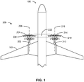
- FIG. 1 shows a top view of a typical existing propulsion system 200 for aircraft 100 that includes at least two propulsion engines 202, 212 mounted on wings 104 of aircraft 100.
- First propulsion engine 202 includes at least one first propulsive fan 204 that rotates within first fan plane 208 perpendicular to first engine longitudinal rotational axis 206.
- second propulsion engine 212 includes at least one second propulsive fan 214 that rotates within second fan plane 218 perpendicular to second engine longitudinal rotational axis 216.
- first fan plane 208 and second fan plane 218 are aligned with one another.
- first propulsion engine 202 and/or second propulsion engine 212 are shifted in an axial direction, defined herein as a direction parallel to longitudinal axis 106 extending along fuselage 102 of aircraft 100.
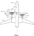
- FIG. 2 shows a top view of exemplary propulsion system 300 for aircraft 100 in one embodiment.
- First propulsion engine 202 is axially spaced relative to second propulsion engine 212 in a direction parallel to aircraft longitudinal axis 106. Consequently, potential cross-engine debris path 222 in the event of a rotor release of first propulsive fan 204 does not impact second fan plane 218.
- first propulsion engine 202 may further include first aft propulsive fan 210 and associated first aft fan plane 226.
- Axial spacing 224 further staggers first aft fan plane 226 ahead of second fan plane 218, thereby reducing the risk of cross-engine debris impact on second propulsion engine 212 in the event of a rotor failure of first aft propulsive fan 210.
- FIG. 3 shows a top view of another exemplary propulsion system 400 for aircraft 100 in one embodiment.
- First propulsion engine 202 is splayed away from second propulsion engine 212, thereby rotating first fan plane 208 relative to second fan plane 218. Consequently, potential cross-engine debris path 222 in the event of a rotor release of first propulsive fan 204 does not impact second fan plane 218.
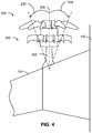
- FIG. 4 shows a close-up top view of first propulsion engine 202.
- first engine longitudinal rotational axis 206 and/or second propulsion engine 212 is splayed at either inboard toe angle 228 or at outboard toe angle 230.
- inboard toe angle 228 is defined as a rotation of first engine longitudinal rotational axis 206 toward fuselage 102 of aircraft 100 and by extension toward second propulsion engine 212 mounted on opposite wing 104 (not illustrated).
- outboard toe angle 230 is defined as a rotation of first engine longitudinal rotational axis 206 away from fuselage 102 of aircraft 100 and by extension away from second propulsion engine 212 mounted on opposite wing 104 (not illustrated).
- first propulsion engine 202 and second propulsion engine 212 are splayed, as illustrated in FIG. 3 . In various other embodiments, both of first propulsion engine 202 and second propulsion engine 212 are splayed.
- Toe angles 228, 230 at which first propulsion engine 202 and second propulsion engine 212 are splayed are independently selected. In one embodiment, inboard toe angle 228 ranges from about 0° (parallel to aircraft longitudinal axis 106) to about 20° and outboard toe angle 230 ranges from about 0° (parallel to aircraft longitudinal axis 106) to about 20°.
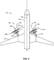
- FIG. 5 shows a top view of another exemplary propulsion system 500 for aircraft 100 in one embodiment.
- First propulsion engine 202 and second propulsion engine 212 are splayed in the same direction, thereby rotating first fan plane 208 and second fan plane 218 relative to one another. Consequently, potential cross-engine debris path 222 in the event of a rotor release of first propulsive fan 204 does not impact second fan plane 218 or vice-versa.
- first propulsion engine 202 is splayed at outboard toe angle 230 and second propulsion engine 212 is splayed at inboard toe angle 228, as illustrated in FIG. 5 , or vice-versa (not illustrated).
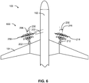
- FIG. 6 shows a top view of another exemplary propulsion system 600 for aircraft 100 in one embodiment.
- First propulsion engine 202 and second propulsion engine 212 are splayed in opposite directions, thereby rotating first fan plane 208 and second fan plane 218 relative to one another. Consequently, potential cross-engine debris path 222 in the event of a rotor release of first propulsive fan 204 does not impact second fan plane 218 or vice-versa.
- both first propulsion engine 202 and second propulsion engine 212 are splayed at outboard toe angle 230, as illustrated in FIG. 6
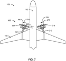
- both first propulsion engine 202 and second propulsion engine 212 are splayed at inboard toe angle 228, as illustrated in FIG. 7 .
- first propulsion engine 202 is axially spaced at axial spacing 224 relative to second propulsion engine 212 and first propulsion engine 202 is additionally splayed at outboard toe angle 230.
- FIG. 8 shows a top view of another exemplary propulsion system 700 for aircraft 100 in one embodiment.
- First propulsion engine 202 is axially displaced by axial spacing 224 relative to second propulsion engine 212 and first propulsion engine 202 is splayed at outboard toe angle 230 away from second propulsion engine 212. Consequently, potential cross-engine debris path 222 in the event of a rotor release of first propulsive fan 204 does not impact second fan plane 218 and vice-versa.
- First propulsion engine 202 is axially displaced by axial spacing 224 relative to second propulsion engine 212 and first propulsion engine 202 is splayed at inboard toe angle 228 toward second propulsion engine 212. Consequently, potential cross-engine debris path 222 in the event of a rotor release of first propulsive fan 204 does not impact second fan plane 218 and vice-versa.
- the method includes any combination of axial spacing 224 and splaying of the first propulsion engine 202 and/or the second propulsion engine 212 in any combination without limitation.
- Exemplary embodiments of propulsion systems 200, 300, 400, 500, 600, 700, 800 mounted on aircraft 100 using the method are described herein above and illustrated as FIGS. 1-9 .
- the at least two propulsion engines of the propulsion system include, but are not limited to, prop-fan engines.
- a non-limiting example of a suitable prop-fan engine includes a dual propeller, contra-rotating prop-fan engine that includes a front propeller and an aft propeller.
- propulsion systems that include at least two propulsion engines are described above in detail.
- the propulsion systems, and methods of operating such systems and devices are not limited to the specific embodiments described herein, but rather, components of systems and/or steps of the methods may be utilized independently and separately from other components and/or steps described herein.
- the methods may also be used in combination with other systems requiring non-alignment of the fan planes associated with the at least two propulsion engines of the other systems, and are not limited to practice with only the systems and methods as described herein.
- the exemplary embodiments can be implemented and utilized in connection with many other aircraft propulsion system applications that are currently configured to receive and accept at least two propulsion engines.
Landscapes
- Engineering & Computer Science (AREA)
- Aviation & Aerospace Engineering (AREA)
- Structures Of Non-Positive Displacement Pumps (AREA)
Abstract
A propulsion system 300,400,500,600,700,800 for an aircraft 100 includes at least two propulsion engines 202,212. Each propulsion engine 202,212 with a longitudinal rotational axis 206,216, and a propulsive fan 204,214 associated with each propulsion engine 202,212 rotates in a plane 208,218 perpendicular to the longitudinal rotational axis 206,216. Each plane 208,218 is at least one of: spaced axially along a longitudinal axis of the aircraft 100, and canted such that each plane 208,218 does not intersect any other plane 208,218 associated with another propulsion engine 202,212 and propulsive fan 204,214.
Description
- At least some known aircraft include open rotor configurations for their engines. For example, open rotor propulsion systems may include turboprops and counter rotating open rotors. Release of a fan blade from one engine may have a potential to cause debris from the affected engine to impact portions of another of the aircraft's engines. Such an impact may negatively affect the other engines such that they may fail as well. Installing a cowling or other shielding device to limit the effect of a blade release adds weight and drag to the aircraft which would also negatively impact fuel efficiency of the aircraft.
- In one aspect according to the present invention, propulsion system for an aircraft is provided. The propulsion system includes at least two propulsion engines. Each propulsion engine rotates about a longitudinal rotational axis, and a propulsive fan associated with each propulsion engine rotates in a plane perpendicular to the longitudinal rotational axis. Each plane is at least one of spaced axially along a fuselage of the aircraft and canted such that each plane does not intersect any other propulsion engine and propulsive fan.
- In another aspect, a method for mounting a propulsion system that includes at least two propulsion engines on an aircraft is provided. Each propulsion engine rotates about a longitudinal rotational axis, and a propulsive fan associated with each propulsion engine rotates in a plane perpendicular to the longitudinal rotational axis. The method includes at least one of spacing each plane associated with each propulsion engine axially along a longitudinal axis of the aircraft, and canting at least one plane associated with at least one propulsion engine. Each plane associated with each propulsion engine does not intersect any other propulsion engine and propulsive fan.
- Various features, aspects, and advantages of the present disclosure will become better understood when the following detailed description is read with reference to the accompanying drawings in which like characters represent like parts throughout the drawings, wherein:
-
FIG. 1 is a top view of an aircraft with twin propulsion engines mounted symmetrically on each wing of the aircraft; -
FIG. 2 is a top view of an aircraft with a first propulsion engine mounted axially forward of a second propulsion engine; -
FIG. 3 is a top view of an aircraft with a first propulsion engine canted away from a second propulsion engine; -
FIG. 4 is a top close-up view of an aircraft showing a range of toe angles at which a propulsion engine is canted; -
FIG. 5 is a top view of an aircraft with both propulsion engines canted in the same direction; -
FIG. 6 is a top view of an aircraft with both propulsion engines canted outboard; -
FIG. 7 is a top view of an aircraft with both propulsion engines canted inboard; -
FIG. 8 is a top view of an aircraft with a first propulsion engine mounted axially forward of a second propulsion engine and canted away from the second propulsion engine; and -
FIG. 9 is a top view of an aircraft with a first propulsion engine mounted axially forward of a second propulsion engine and canted toward the second propulsion engine. - Unless otherwise indicated, the drawings provided herein are meant to illustrate features of embodiments of this disclosure. These features are believed to be applicable in a wide variety of systems comprising one or more embodiments of this disclosure. As such, the drawings are not meant to include all conventional features known by those of ordinary skill in the art to be required for the practice of the embodiments disclosed herein.
- In the following specification and the claims, reference will be made to a number of terms, which shall be defined to have the following meanings.
- The singular forms "a", "an", and "the" include plural references unless the context clearly dictates otherwise.
- "Optional" or "optionally" means that the subsequently described event or circumstance may or may not occur, and that the description includes instances where the event occurs and instances where it does not.
- Approximating language, as used herein throughout the specification and claims, may be applied to modify any quantitative representation that could permissibly vary without resulting in a change in the basic function to which it is related. Accordingly, a value modified by a term or terms, such as "about", "approximately", and "substantially", are not to be limited to the precise value specified. In at least some instances, the approximating language may correspond to the precision of an instrument for measuring the value. Here and throughout the specification and claims, range limitations may be combined and/or interchanged, such ranges are identified and include all the sub-ranges contained therein unless context or language indicates otherwise.
- The aircraft engine systems described herein provide cost-effective methods for providing a multi-engine propulsion system with enhanced operational safety and reliability. In particular, the propulsion systems described herein include at least two propulsion engines mounted so that each propulsion engine is axially spaced and/or splayed relative to each other propulsion engine of the propulsion system. In this arrangement, a plane of rotation of each fan rotor for each engine does not intersect any other propulsion engine of the propulsion system. In the case of a rotor release by any one of the propulsion engines of the propulsion system, any resulting cross-engine debris is directed away from any of the other propulsion engines, thereby reducing the risk of impact and associated damage due to cross-engine debris strikes. In various embodiments described herein, any combination of axial spacing and splaying may be used to situate each plane of rotation of each fan rotor in non-alignment with all other planes of rotation of all other fan rotors for all propulsion engines of the multi-engine propulsion system.
- The multi-engine propulsion system that includes staggered and/or splayed propulsion engines offers advantages over known methods of providing protection against cross-engine debris strikes, such as the incorporation of fuselage armoring or other protective structures into the design of the aircraft propulsion system. These known methods add weight to the aircraft, thereby increasing the aircraft's fuel use. In addition, the incorporation of armoring increases the complexity of the aircraft design, and potentially introduces handedness constraints to the design and installation of the at least two propulsion engines of the propulsion system. The multi-engine propulsion system described herein enables the incorporation of highly efficient open-rotor propulsion engine designs without compromising the safety or reliability of the propulsion system.
-
FIG. 1 shows a top view of a typical existingpropulsion system 200 foraircraft 100 that includes at least twopropulsion engines wings 104 ofaircraft 100.First propulsion engine 202 includes at least one firstpropulsive fan 204 that rotates withinfirst fan plane 208 perpendicular to first engine longitudinalrotational axis 206. Similarly,second propulsion engine 212 includes at least one secondpropulsive fan 214 that rotates withinsecond fan plane 218 perpendicular to second engine longitudinalrotational axis 216. In existingpropulsion system 200 illustrated inFIG. 1 ,first fan plane 208 andsecond fan plane 218 are aligned with one another. Consequently, in the event of a rotor release of either firstpropulsive fan 204 or secondpropulsive fan 214, potentialcross-engine debris path 222 of any resulting cross-engine debris is directed between firstpropulsive fan 204 and secondpropulsive fan 214. - In some embodiments,
first propulsion engine 202 and/orsecond propulsion engine 212 are shifted in an axial direction, defined herein as a direction parallel tolongitudinal axis 106 extending alongfuselage 102 ofaircraft 100.FIG. 2 shows a top view ofexemplary propulsion system 300 foraircraft 100 in one embodiment.First propulsion engine 202 is axially spaced relative tosecond propulsion engine 212 in a direction parallel to aircraftlongitudinal axis 106. Consequently, potentialcross-engine debris path 222 in the event of a rotor release of firstpropulsive fan 204 does not impactsecond fan plane 218. In some embodiments,first propulsion engine 202 may further include first aftpropulsive fan 210 and associated firstaft fan plane 226.Axial spacing 224 further staggers firstaft fan plane 226 ahead ofsecond fan plane 218, thereby reducing the risk of cross-engine debris impact onsecond propulsion engine 212 in the event of a rotor failure of first aftpropulsive fan 210. -
FIG. 3 shows a top view of anotherexemplary propulsion system 400 foraircraft 100 in one embodiment.First propulsion engine 202 is splayed away fromsecond propulsion engine 212, thereby rotatingfirst fan plane 208 relative tosecond fan plane 218. Consequently, potentialcross-engine debris path 222 in the event of a rotor release of firstpropulsive fan 204 does not impactsecond fan plane 218. -
FIG. 4 shows a close-up top view offirst propulsion engine 202. In various embodiments, first engine longitudinalrotational axis 206 and/orsecond propulsion engine 212 is splayed at eitherinboard toe angle 228 or atoutboard toe angle 230. As used herein,inboard toe angle 228 is defined as a rotation of first engine longitudinalrotational axis 206 towardfuselage 102 ofaircraft 100 and by extension towardsecond propulsion engine 212 mounted on opposite wing 104 (not illustrated). As used herein,outboard toe angle 230 is defined as a rotation of first engine longitudinalrotational axis 206 away fromfuselage 102 ofaircraft 100 and by extension away fromsecond propulsion engine 212 mounted on opposite wing 104 (not illustrated). - In various embodiments, only one of
first propulsion engine 202 andsecond propulsion engine 212 is splayed, as illustrated inFIG. 3 . In various other embodiments, both offirst propulsion engine 202 andsecond propulsion engine 212 are splayed.Toe angles first propulsion engine 202 andsecond propulsion engine 212 are splayed are independently selected. In one embodiment,inboard toe angle 228 ranges from about 0° (parallel to aircraft longitudinal axis 106) to about 20° andoutboard toe angle 230 ranges from about 0° (parallel to aircraft longitudinal axis 106) to about 20°. -
FIG. 5 shows a top view of anotherexemplary propulsion system 500 foraircraft 100 in one embodiment.First propulsion engine 202 andsecond propulsion engine 212 are splayed in the same direction, thereby rotatingfirst fan plane 208 andsecond fan plane 218 relative to one another. Consequently, potentialcross-engine debris path 222 in the event of a rotor release of firstpropulsive fan 204 does not impactsecond fan plane 218 or vice-versa. In order to be splayed in the same direction,first propulsion engine 202 is splayed atoutboard toe angle 230 andsecond propulsion engine 212 is splayed atinboard toe angle 228, as illustrated inFIG. 5 , or vice-versa (not illustrated). -
FIG. 6 shows a top view of anotherexemplary propulsion system 600 foraircraft 100 in one embodiment.First propulsion engine 202 andsecond propulsion engine 212 are splayed in opposite directions, thereby rotatingfirst fan plane 208 andsecond fan plane 218 relative to one another. Consequently, potentialcross-engine debris path 222 in the event of a rotor release of firstpropulsive fan 204 does not impactsecond fan plane 218 or vice-versa. In order to be splayed in opposite directions, bothfirst propulsion engine 202 andsecond propulsion engine 212 are splayed atoutboard toe angle 230, as illustrated inFIG. 6 , or bothfirst propulsion engine 202 andsecond propulsion engine 212 are splayed atinboard toe angle 228, as illustrated inFIG. 7 . - In various embodiments,
first propulsion engine 202 is axially spaced ataxial spacing 224 relative tosecond propulsion engine 212 andfirst propulsion engine 202 is additionally splayed atoutboard toe angle 230.FIG. 8 shows a top view of anotherexemplary propulsion system 700 foraircraft 100 in one embodiment.First propulsion engine 202 is axially displaced byaxial spacing 224 relative tosecond propulsion engine 212 andfirst propulsion engine 202 is splayed atoutboard toe angle 230 away fromsecond propulsion engine 212. Consequently, potentialcross-engine debris path 222 in the event of a rotor release of firstpropulsive fan 204 does not impactsecond fan plane 218 and vice-versa.FIG. 9 shows a top view of anotherexemplary propulsion system 200 foraircraft 100 in one embodiment.First propulsion engine 202 is axially displaced byaxial spacing 224 relative tosecond propulsion engine 212 andfirst propulsion engine 202 is splayed atinboard toe angle 228 towardsecond propulsion engine 212. Consequently, potentialcross-engine debris path 222 in the event of a rotor release of firstpropulsive fan 204 does not impactsecond fan plane 218 and vice-versa. - In various embodiments, a method for mounting a multi-engine propulsion system that includes at least two propulsion engines on an aircraft is disclosed herein. The method includes any one of axially displacing
first propulsion engine 202 relative tosecond propulsion engine 212 and splayingfirst propulsion engine 202 and/orsecond propulsion engine 212 atinboard toe angle 228 or atoutboard toe angle 230 as described herein previously. The method includes any combination ofaxial spacing 224 and splaying of thefirst propulsion engine 202 and/or thesecond propulsion engine 212 in any combination without limitation. Exemplary embodiments ofpropulsion systems aircraft 100 using the method are described herein above and illustrated asFIGS. 1-9 . - In various embodiments, the at least two propulsion engines of the propulsion system include, but are not limited to, prop-fan engines. A non-limiting example of a suitable prop-fan engine includes a dual propeller, contra-rotating prop-fan engine that includes a front propeller and an aft propeller.
- Exemplary embodiments of propulsion systems that include at least two propulsion engines are described above in detail. The propulsion systems, and methods of operating such systems and devices are not limited to the specific embodiments described herein, but rather, components of systems and/or steps of the methods may be utilized independently and separately from other components and/or steps described herein. For example, the methods may also be used in combination with other systems requiring non-alignment of the fan planes associated with the at least two propulsion engines of the other systems, and are not limited to practice with only the systems and methods as described herein. Rather, the exemplary embodiments can be implemented and utilized in connection with many other aircraft propulsion system applications that are currently configured to receive and accept at least two propulsion engines.
- Although specific features of various embodiments of the disclosure may be shown in some drawings and not in others, this is for convenience only. In accordance with the principles of the disclosure, any feature of a drawing may be referenced and/or claimed in combination with any feature of any other drawing.
- This written description uses examples to disclose the embodiments, including the preferred mode, and also to enable any person skilled in the art to practice the embodiments, including making and using any devices or systems and performing any incorporated methods. The patentable scope of the disclosure is defined by the claims, and may include other examples that occur to those skilled in the art. Such other examples are intended to be within the scope of the claims if they have structural elements that do not differ from the literal language of the claims, or if they include equivalent structural elements with insubstantial differences from the literal language of the claims.
- Various aspects and embodiments of the present invention are defined by the following numbered clauses:
- 1. A propulsion system for an aircraft comprising:
- at least two propulsion engines, each said propulsion engine rotating about a respective longitudinal rotational axis; and
- 2. The propulsion system of clause 1, wherein said at least two propulsion engines comprise a first propulsion engine and a second propulsion engine, said first propulsion engine is canted.
- 3. The propulsion system of any preceding clause, wherein said second propulsion engine is canted.
- 4. The propulsion system of any preceding clause, wherein said first propulsion engine and said second propulsion engine are canted in the same direction.
- 5. The propulsion system of any preceding clause, wherein said first propulsion engine and said second propulsion engine are canted in different directions.
- 6. The propulsion system of any preceding clause, wherein said at least two propulsion engines comprise a first propulsion engine and a second propulsion engine, said first propulsion engine axially spaced from said second propulsion engine and canted away from said second propulsion engine.
- 7. The propulsion system of any preceding clause, wherein said at least two propulsion engines comprise a first propulsion engine and a second propulsion engine, said first propulsion engine axially spaced from said second propulsion engine and canted towards said second propulsion engine.
- 8. The propulsion system of any preceding clause, wherein said at least two propulsion engines are prop-fan engines, each prop-fan engine being dual propeller, contra-rotating, including a front propeller and an aft propeller.
- 9. The propulsion system of any preceding clause, wherein at least one of said at least two propulsion engines is canted at a toe angle ranging from about 20 degrees inboard to about 20 degrees outboard.
- 10. The propulsion system of any preceding clause, wherein each of said at least two propulsion engines is operated at different thrust levels to compensate for asymmetric torques resulting from at least one of said axial spacing and canting of each of said at least two propulsion engines.
- 11. A method for mounting a propulsion system comprising at least two propulsion engines on an aircraft, wherein each propulsion engine rotates about a longitudinal rotational axis, a propulsive fan associated with each propulsion engine rotates in a plane perpendicular to the longitudinal rotational axis, the method comprising at least one of:
- spacing each plane associated with each propulsion engine axially along a longitudinal axis of the aircraft; and
- canting at least one plane associated with at least one propulsion engine;
- 12. The method of any preceding clause, wherein a first propulsion engine of the at least two propulsion engines is canted.
- 13. The method of any preceding clause, wherein the first propulsion engine and a second propulsion engine of the at least two propulsion engines are canted.
- 14. The method of any preceding clause, wherein the first propulsion engine and the second propulsion engine are canted in the same direction.
- 15. The method of any preceding clause, wherein the first propulsion engine and the second propulsion engine are canted in different directions.
- 16. The method of any preceding clause, wherein a first propulsion engine of the at least two propulsion engines is axially spaced from a second propulsion engine of the at least two propulsion engines and the first propulsion engine is canted away from the second propulsion engine.
- 17. The method of any preceding clause, wherein a first propulsion engine of the at least two propulsion engines is axially spaced from a second propulsion engine of the at least two propulsion engines and the first propulsion engine is canted towards the second propulsion engine.
- 18. The method of any preceding clause, wherein the at least two propulsion engines are prop-fan engines, each prop-fan engine being dual propeller, contra-rotating, including a front propeller and an aft propeller.
- 19. The method of any preceding clause, wherein at least one of the at least two propulsion engines is canted at a toe angle ranging from about 20 degrees inboard to about 20 degrees outboard.
- 20. The method of any preceding clause, wherein each of the at least two propulsion engines of the propulsion system is operated at different thrust levels to compensate for asymmetric torques resulting from at least one of the axial spacing and canting of each of the at least two propulsion engines.
Claims (10)
- A propulsion system (300,400,500,600,700,800) for an aircraft (100) comprising:at least two propulsion engines (202,212), each the propulsion engine (202,212) rotating about a respective longitudinal rotational axis (206,216); anda propulsive fan (204,214) associated with each the propulsion engine (202,212) rotating in a plane (208,218) perpendicular to the respective longitudinal rotational axis(206,216), each plane (208,218) positioned at least one of spaced axially along a longitudinal axis (106) of the aircraft (100) and canted such that each plane (208,218) does not intersect any other propulsion engine (202,212) and propulsive fan (204,214).
- The propulsion system (400,500,600;700,800) of claim 1, wherein the at least two propulsion engines (202,212) comprise a first propulsion engine (202) and a second propulsion engine (212), the first propulsion engine (202) is canted.
- The propulsion system (500,600) of claim 2, wherein the second propulsion engine (212) is canted.
- The propulsion system (500) of claim 2 or claim 3, wherein the first propulsion engine (202) and the second propulsion engine (212) are canted in the same direction.
- The propulsion system (600) of claim 2 or claim 3, wherein the first propulsion engine (202) and the second propulsion engine (212) are canted in different directions.
- The propulsion system (700) of any preceding claim, wherein the at least two propulsion engines (202,212) comprise a first propulsion engine (202) and a second propulsion engine (212), the first propulsion engine (202) axially spaced from the second propulsion engine (212) and canted away from the second propulsion engine (212).
- The propulsion system (800) of any preceding claim, wherein the at least two propulsion engines (202,212) comprise a first propulsion engine (202) and a second propulsion engine (212), the first propulsion engine (202) axially spaced from the second propulsion engine (212) and canted towards the second propulsion engine (212).
- The propulsion system (300,400,500,600,700,800) of any preceding claim, wherein the at least two propulsion engines (202,212) are prop-fan engines, each prop-fan engine being dual propeller, contra-rotating, including a front propulsive fan (204) and an aft propulsive fan (210).
- The propulsion system (400,500,600,700,800) of any preceding claim, wherein at least one the at least two propulsion engines (202,212) is canted at a toe angle (226,228) ranging from about 20 degrees inboard to about 20 degrees outboard.
- The propulsion system (300,400,500,600,700,800) of any preceding claim, wherein each of the at least two propulsion engines (202,212) is operated at different thrust levels to compensate for asymmetric torques resulting from at least one of the axial spacing and canting of each of the at least two propulsion engines (202,212).
Applications Claiming Priority (1)
| Application Number | Priority Date | Filing Date | Title |
|---|---|---|---|
| US14/923,062 US10442541B2 (en) | 2015-10-26 | 2015-10-26 | Method and system for cross engine debris avoidance |
Publications (1)
| Publication Number | Publication Date |
|---|---|
| EP3165453A1 true EP3165453A1 (en) | 2017-05-10 |
Family
ID=57144863
Family Applications (1)
| Application Number | Title | Priority Date | Filing Date |
|---|---|---|---|
| EP16194096.0A Withdrawn EP3165453A1 (en) | 2015-10-26 | 2016-10-17 | Method and system for cross engine debris avoidance |
Country Status (6)
| Country | Link |
|---|---|
| US (1) | US10442541B2 (en) |
| EP (1) | EP3165453A1 (en) |
| JP (1) | JP2017081542A (en) |
| CN (1) | CN107010230A (en) |
| BR (1) | BR102016024919A2 (en) |
| CA (1) | CA2945101A1 (en) |
Families Citing this family (7)
| Publication number | Priority date | Publication date | Assignee | Title |
|---|---|---|---|---|
| JP6731604B2 (en) * | 2018-03-31 | 2020-07-29 | 中松 義郎 | High-speed drones and other aircraft |
| CN108716434A (en) * | 2018-05-23 | 2018-10-30 | 中国空气动力研究与发展中心计算空气动力研究所 | A kind of Automatic-boosting structure of aviation piston |
| US12384522B2 (en) * | 2023-08-04 | 2025-08-12 | General Electric Company | Aircraft with an unducted fan propulsor |
| US12365471B2 (en) | 2023-08-04 | 2025-07-22 | General Electric Company | Aircraft with an unducted fan propulsor |
| US12365446B2 (en) | 2023-08-04 | 2025-07-22 | General Electric Company | Aircraft with an unducted fan propulsor |
| US20250214703A1 (en) * | 2023-12-29 | 2025-07-03 | Rtx Corporation | Blended wing body aircraft system |
| WO2025250927A1 (en) * | 2024-05-30 | 2025-12-04 | General Electric Company | Aircraft with an unducted fan propulsor |
Citations (5)
| Publication number | Priority date | Publication date | Assignee | Title |
|---|---|---|---|---|
| US20030168552A1 (en) * | 2002-03-05 | 2003-09-11 | Brown Paul Anthony | Aircraft propulsion system and method |
| US20100019081A1 (en) * | 2008-04-02 | 2010-01-28 | Airbus France | Airplane with pitch and yaw command by propulsion system |
| FR2965250A1 (en) * | 2010-09-28 | 2012-03-30 | Snecma | INSTALLATION OF ENGINES AT THE REAR OF THE FUSELAGE OF AN AIRCRAFT, AND AIRCRAFT EQUIPPED WITH SUCH A INSTALLATION. |
| EP2738092A2 (en) * | 2012-11-28 | 2014-06-04 | The Boeing Company | System and method for minimizing wave drag through bilaterally asymmetric design |
| US20140252159A1 (en) * | 2013-03-05 | 2014-09-11 | Rolls-Royce Plc | Engine installation |
Family Cites Families (16)
| Publication number | Priority date | Publication date | Assignee | Title |
|---|---|---|---|---|
| US1996750A (en) * | 1931-06-12 | 1935-04-09 | Autogiro Co Of America | Autorotative wing aircraft |
| US3666211A (en) | 1970-03-12 | 1972-05-30 | Mc Donnell Douglas Corp | Trijet aircraft |
| US4976396A (en) | 1987-11-13 | 1990-12-11 | The Boeing Company | Aircraft configuration with aft mounted engines |
| CN1061004A (en) * | 1991-04-21 | 1992-05-13 | 安拴印 | But the turbine aeroplane of vertical takeoff and landing |
| IT1308096B1 (en) * | 1999-06-02 | 2001-11-29 | Finmeccanica Spa | TILTROTOR |
| US6655631B2 (en) * | 2000-07-28 | 2003-12-02 | John Frederick Austen-Brown | Personal hoverplane with four tiltmotors |
| US6896221B1 (en) * | 2003-04-16 | 2005-05-24 | Einar Einarsson | Vertical takeoff and landing aircraft |
| US8720814B2 (en) * | 2005-10-18 | 2014-05-13 | Frick A. Smith | Aircraft with freewheeling engine |
| FR2909359B1 (en) | 2006-11-30 | 2009-09-25 | Airbus France Sas | AIRPLANE WITH REACTORS ARRANGED AT THE BACK |
| GB0702608D0 (en) * | 2007-02-10 | 2007-03-21 | Rolls Royce Plc | Aeroengine |
| US8256704B2 (en) * | 2007-08-14 | 2012-09-04 | Lapcad Engineering, Inc. | Vertical/short take-off and landing aircraft |
| US7900868B2 (en) | 2007-08-27 | 2011-03-08 | The Boeing Company | Noise-shielding wing configuration |
| FR2943039B1 (en) | 2009-03-12 | 2012-09-28 | Airbus France | PLANE TANK-TAIL AND REVERSE ENGINE. |
| US8800912B2 (en) * | 2009-10-09 | 2014-08-12 | Oliver Vtol, Llc | Three wing, six-tilt propulsion unit, VTOL aircraft |
| US8393567B2 (en) * | 2010-11-15 | 2013-03-12 | The Boeing Company | Method and apparatus for reducing aircraft noise |
| US9284843B2 (en) | 2013-03-13 | 2016-03-15 | The Boeing Company | Blade safety mechanism for open rotor engine system |
-
2015
- 2015-10-26 US US14/923,062 patent/US10442541B2/en active Active
-
2016
- 2016-10-13 CA CA2945101A patent/CA2945101A1/en not_active Abandoned
- 2016-10-17 EP EP16194096.0A patent/EP3165453A1/en not_active Withdrawn
- 2016-10-18 JP JP2016203996A patent/JP2017081542A/en active Pending
- 2016-10-25 BR BR102016024919-8A patent/BR102016024919A2/en not_active Application Discontinuation
- 2016-10-26 CN CN201610947135.8A patent/CN107010230A/en active Pending
Patent Citations (5)
| Publication number | Priority date | Publication date | Assignee | Title |
|---|---|---|---|---|
| US20030168552A1 (en) * | 2002-03-05 | 2003-09-11 | Brown Paul Anthony | Aircraft propulsion system and method |
| US20100019081A1 (en) * | 2008-04-02 | 2010-01-28 | Airbus France | Airplane with pitch and yaw command by propulsion system |
| FR2965250A1 (en) * | 2010-09-28 | 2012-03-30 | Snecma | INSTALLATION OF ENGINES AT THE REAR OF THE FUSELAGE OF AN AIRCRAFT, AND AIRCRAFT EQUIPPED WITH SUCH A INSTALLATION. |
| EP2738092A2 (en) * | 2012-11-28 | 2014-06-04 | The Boeing Company | System and method for minimizing wave drag through bilaterally asymmetric design |
| US20140252159A1 (en) * | 2013-03-05 | 2014-09-11 | Rolls-Royce Plc | Engine installation |
Also Published As
| Publication number | Publication date |
|---|---|
| JP2017081542A (en) | 2017-05-18 |
| CA2945101A1 (en) | 2017-04-26 |
| US20170113805A1 (en) | 2017-04-27 |
| CN107010230A (en) | 2017-08-04 |
| BR102016024919A2 (en) | 2017-07-18 |
| US10442541B2 (en) | 2019-10-15 |
Similar Documents
| Publication | Publication Date | Title |
|---|---|---|
| EP3165453A1 (en) | Method and system for cross engine debris avoidance | |
| CA2974992C (en) | Airframe-integrated propeller-driven propulsion systems | |
| US9994330B2 (en) | Aircraft | |
| EP3187723B1 (en) | System for in-line distributed propulsion | |
| US11919629B2 (en) | Vertical takeoff and landing aircraft configuration | |
| EP3441309A1 (en) | Adjustable blade balance module | |
| US10001063B2 (en) | Angled core gas turbine engine mounting | |
| US3333794A (en) | Guards for air intakes of jet engines | |
| EP2853493A1 (en) | Helicopter with engine air intakes | |
| US10351229B2 (en) | Metallic dimpled doubler | |
| US11718403B2 (en) | Extremely quiet short take-off and landing (STOL) aircraft | |
| US8991742B2 (en) | Asymmetrical single main rotor unmanned aerial vehicle | |
| US10086935B2 (en) | Guide vanes for a pusher propeller for rotary wing aircraft | |
| DE102011117542A1 (en) | Adjustable or rigid propeller of aircraft e.g. rigid wing airplane flying in transonic region, has propeller blades whose one end is connected with hub and other end is connected together by ring to which shortened blades are attached | |
| US11814174B2 (en) | Layered fuselage shield | |
| US10723451B2 (en) | Propeller rotor for a vertical take off and landing aircraft | |
| US11999472B2 (en) | Rotor blade non-counterbored retention assembly via a sliding clamped bushing | |
| US10124906B2 (en) | Splined muff | |
| US9580187B2 (en) | Rotor index sensor system | |
| US10611471B2 (en) | Light weight rigid rotor with blade fold capability | |
| US8876037B2 (en) | Rotorcraft counter-torque control assembly and method | |
| US11148822B2 (en) | Drive system arrangement for rotorcraft |
Legal Events
| Date | Code | Title | Description |
|---|---|---|---|
| PUAI | Public reference made under article 153(3) epc to a published international application that has entered the european phase |
Free format text: ORIGINAL CODE: 0009012 |
|
| AK | Designated contracting states |
Kind code of ref document: A1 Designated state(s): AL AT BE BG CH CY CZ DE DK EE ES FI FR GB GR HR HU IE IS IT LI LT LU LV MC MK MT NL NO PL PT RO RS SE SI SK SM TR |
|
| AX | Request for extension of the european patent |
Extension state: BA ME |
|
| STAA | Information on the status of an ep patent application or granted ep patent |
Free format text: STATUS: THE APPLICATION IS DEEMED TO BE WITHDRAWN |
|
| 18D | Application deemed to be withdrawn |
Effective date: 20171111 |