EP3165372A1 - Apparatus for cooling media sheets - Google Patents
Apparatus for cooling media sheets Download PDFInfo
- Publication number
- EP3165372A1 EP3165372A1 EP15192689.6A EP15192689A EP3165372A1 EP 3165372 A1 EP3165372 A1 EP 3165372A1 EP 15192689 A EP15192689 A EP 15192689A EP 3165372 A1 EP3165372 A1 EP 3165372A1
- Authority
- EP
- European Patent Office
- Prior art keywords
- sheets
- cooling
- cooling units
- conveyer
- path
- Prior art date
- Legal status (The legal status is an assumption and is not a legal conclusion. Google has not performed a legal analysis and makes no representation as to the accuracy of the status listed.)
- Granted
Links
Images
Classifications
-
- B—PERFORMING OPERATIONS; TRANSPORTING
- B41—PRINTING; LINING MACHINES; TYPEWRITERS; STAMPS
- B41J—TYPEWRITERS; SELECTIVE PRINTING MECHANISMS, i.e. MECHANISMS PRINTING OTHERWISE THAN FROM A FORME; CORRECTION OF TYPOGRAPHICAL ERRORS
- B41J13/00—Devices or arrangements of selective printing mechanisms, e.g. ink-jet printers or thermal printers, specially adapted for supporting or handling copy material in short lengths, e.g. sheets
- B41J13/009—Diverting sheets at a section where at least two sheet conveying paths converge, e.g. by a movable switching guide that blocks access to one conveying path and guides the sheet to another path, e.g. when a sheet conveying direction is reversed after printing on the front of the sheet has been finished and the sheet is guided to a sheet turning path for printing on the back
-
- B—PERFORMING OPERATIONS; TRANSPORTING
- B41—PRINTING; LINING MACHINES; TYPEWRITERS; STAMPS
- B41J—TYPEWRITERS; SELECTIVE PRINTING MECHANISMS, i.e. MECHANISMS PRINTING OTHERWISE THAN FROM A FORME; CORRECTION OF TYPOGRAPHICAL ERRORS
- B41J11/00—Devices or arrangements of selective printing mechanisms, e.g. ink-jet printers or thermal printers, for supporting or handling copy material in sheet or web form
- B41J11/0015—Devices or arrangements of selective printing mechanisms, e.g. ink-jet printers or thermal printers, for supporting or handling copy material in sheet or web form for treating before, during or after printing or for uniform coating or laminating the copy material before or after printing
-
- B—PERFORMING OPERATIONS; TRANSPORTING
- B41—PRINTING; LINING MACHINES; TYPEWRITERS; STAMPS
- B41J—TYPEWRITERS; SELECTIVE PRINTING MECHANISMS, i.e. MECHANISMS PRINTING OTHERWISE THAN FROM A FORME; CORRECTION OF TYPOGRAPHICAL ERRORS
- B41J29/00—Details of, or accessories for, typewriters or selective printing mechanisms not otherwise provided for
- B41J29/377—Cooling or ventilating arrangements
-
- G—PHYSICS
- G03—PHOTOGRAPHY; CINEMATOGRAPHY; ANALOGOUS TECHNIQUES USING WAVES OTHER THAN OPTICAL WAVES; ELECTROGRAPHY; HOLOGRAPHY
- G03G—ELECTROGRAPHY; ELECTROPHOTOGRAPHY; MAGNETOGRAPHY
- G03G15/00—Apparatus for electrographic processes using a charge pattern
- G03G15/65—Apparatus which relate to the handling of copy material
- G03G15/6555—Handling of sheet copy material taking place in a specific part of the copy material feeding path
- G03G15/6558—Feeding path after the copy sheet preparation and up to the transfer point, e.g. registering; Deskewing; Correct timing of sheet feeding to the transfer point
-
- G—PHYSICS
- G03—PHOTOGRAPHY; CINEMATOGRAPHY; ANALOGOUS TECHNIQUES USING WAVES OTHER THAN OPTICAL WAVES; ELECTROGRAPHY; HOLOGRAPHY
- G03G—ELECTROGRAPHY; ELECTROPHOTOGRAPHY; MAGNETOGRAPHY
- G03G15/00—Apparatus for electrographic processes using a charge pattern
- G03G15/65—Apparatus which relate to the handling of copy material
- G03G15/6555—Handling of sheet copy material taking place in a specific part of the copy material feeding path
- G03G15/657—Feeding path after the transfer point and up to the fixing point, e.g. guides and feeding means for handling copy material carrying an unfused toner image
-
- G—PHYSICS
- G03—PHOTOGRAPHY; CINEMATOGRAPHY; ANALOGOUS TECHNIQUES USING WAVES OTHER THAN OPTICAL WAVES; ELECTROGRAPHY; HOLOGRAPHY
- G03G—ELECTROGRAPHY; ELECTROPHOTOGRAPHY; MAGNETOGRAPHY
- G03G21/00—Arrangements not provided for by groups G03G13/00 - G03G19/00, e.g. cleaning, elimination of residual charge
- G03G21/20—Humidity or temperature control also ozone evacuation; Internal apparatus environment control
Definitions
- the invention relates to an apparatus for cooling media sheets in a printer, the apparatus comprising:
- the media sheets are frequently subjected to processing steps, e.g. a step of fusing a toner image or a step of drying ink, which results in the sheets being heated to an elevated temperature, so that it is necessary to cool them down again after the print process.
- processing steps e.g. a step of fusing a toner image or a step of drying ink, which results in the sheets being heated to an elevated temperature, so that it is necessary to cool them down again after the print process.
- the sheets may be moved along a cooled stationary part or they may be pressed against a surface of a co-moving member, e.g. a rotating drum having a metal surface with high heat conductivity.
- the drum may be provided with internal cooling fins or the like for transferring the heat withdrawn from the media sheets onto a cooling medium such as a liquid or ambient air or cooled air.
- a cooling medium such as a liquid or ambient air or cooled air.
- US 2014029995 A1 describes a cooling apparatus in which the sheets are successively passed over peripheral surfaces of two cooling drums.
- a switch is provided in the conveyor path for diverting selected ones of the media sheets to a different destination. For example, in a duplex printer, some sheets are to be directed to a discharge tray whereas other sheets are to be re-circulated in a duplex path of the printer.
- JP 2009237514 A discloses an apparatus according to the preamble of claim 1.
- the conveyer comprises a decelerating mechanism for decelerating the sheets in the first conveyer path between the first one of the cooling units and the last one of the cooling units.
- the print process may be such that, in order to obtain a high print quality, the temperature of the sheets at entry into the printing station must not exceed a certain limit. Consequently, in a duplex printer the sheets that have been printed already on one side and have therefore been heated in the print process must be cooled down sufficiently before they are re-circulated for printing on the second side, whereas duplex sheets that have been printed on both sides already or simplex sheets that are to be printed only on one side, anyway, are allowed to have a higher temperature when they are directed to the discharge tray. According to the invention, the sheets for which a higher exit temperature is admissible will bypass the last cooling unit, whereby the energy consumption of this cooling unit is reduced.
- the energy consumption of the last cooling unit may be reduced simply by the fact that only a smaller number of sheets is passed through this unit so that the amount of heat to be removed by this unit is smaller and, consequently, the required amount of cooling air is reduced or the admissible temperature of the cooling air may be higher so that less energy is needed in a refrigerating system for cooling the air.
- the media sheets that have left the first cooling unit are decelerated in the first conveyer path, so that more time is available for cooling the sheets to a lower temperature in the last cooling unit. Consequently, the required low temperature for the sheets to be re-circulated can be reached with reduced total heat absorbing capacity of the cooling units, which permits not only to save energy but also to reduce the space requirement for the cooling units.
- the conveyer comprises a decelerating mechanism for decelerating the sheets in the first conveyer path between the first cooling unit and a second cooling unit.
- the first conveyer path includes a duplex path for recirculating sheets from the second cooling unit to an entry side of the printer.
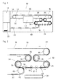
- a printer 10 comprises a printing unit 12, a feeder 14 for feeding media sheets 16, 18 to the printing unit, and a discharge tray 20 onto which printed media sheets 22 are discharged.
- the printing unit 12 employs a print process, e.g. laser printing or ink jet printing, in which the media sheets are heated to an elevated temperature, so that it is necessary to cool the sheets before they are discharged onto the discharge tray 20.
- a sheet cooling apparatus 24 is provided on the exit side of the printing unit 12.
- the cooling apparatus comprises a total of four cooling drums 26 two of which constitute a first cooling unit 28 while the other two constitute a second cooling unit 30. It would also be possible to consider each of the cooling drums as a "cooling unit". However, for the purpose of clarity it is more convenient here to consider a pair of two cooling drums as a cooling unit.
- a conveyer 32 is provided for conveying the media sheets 16, 18 from the feeder 14 to the printing unit 12 and further through both cooling units 28, 30 along a first conveyer path 34.
- the first conveyer path 34 includes also a duplex path 36 along which sheets 18 that have been printed on one side are re-circulated to the entry side of the printing unit 12 for printing an image on the second side.
- blank sheets 16 from the feeder 14 and sheets 18 that have been printed on one side are fed to the printing unit 12 in an interleaved mode, so that the sheets leaving the printing unit 12 form an alternating sequence of single sided copies (sheets 18) and completely printed sheets 22 bearing an image on both sides.
- a switch 38 is provided for diverting the sheets 22 out of the first conveyer path 34 and into a second conveyer path 40 that leads to the discharge tray 20.
- the switch 38 is arranged downstream of the first cooling unit 28 and upstream of the second cooling unit 30, so that the printed (duplex) sheets 22 pass only through the first cooling unit 28 whereas the single sided copies (sheets 18) pass through both cooling units 28 and 30. This permits to cool the sheets 18 to a lower temperature which permits a high print quality in the print process in which an image is printed on the second side of the sheets.
- the first conveyer path 34 includes a train of roller pairs 42 that are disposed at regular intervals between the switch 38 and the first cooling drum 26 of the second cooling unit 30.
- the rollers of each roller pair 42 form a nip for feeding the sheets 18, and at least one roller of each roller pair 42 is actively driven with an individually controllable speed.
- the distance d between two adjacent roller pairs 42 is smaller than the length of the sheets 18 and is approximately equal to the peripheral length 2 ⁇ r of the driven roller (wherein r is the radius of the driven roller).
- the sheets 18 and 22 are conveyed from the printing unit 12 to and through the first cooling unit 28 with a given speed which corresponds to a throughput of 300 sheets per minute, for example.
- the printed sheets 22 are conveyed with the same speed in the second conveyer path 40.
- a controller 44 which has only been shown schematically in Fig. 2 controls the driven rollers of the roller pairs 42 such that each sheet 18 leaving the switch 38 on the first conveyer path 34 is decelerated continuously to only half the speed, so that the throughput in the second cooling unit 30 will be only 150 sheets per minute.
- the dwell time of the sheets 18 on the periphery of the cooling drums 26 of the second cooling unit 30 is twice as high as the dwell time in the first cooling unit 28, so that the sheets 18 to be re-circulated to the printing unit 12 can be cooled more intensely.
- the rollers pairs 42 may for example be controlled as follows.
- the first two rollers pairs 42 are both driven with a speed equal to the speed in the first cooling unit 28.
- the second roller pair is decelerated.
- the third roller pair is driven such that the second and third roller pairs have the same speed when the leading edge of the sheet reaches the third roller pair. The same pattern is used for further decelerating the sheet while passing through the third and fourth roller pairs.
- the two pairs of cooling rollers 26 of the two cooling units 28 and 30 are arranged mirror-symmetrically, with the upstream roller 26 of the first cooling unit and the downstream roller of the second cooling unit 30 being disposed close together and at the same height, whereas the downstream cooling roller of the first cooling unit 28 and the upstream cooling roller of the second cooling unit 30 have a larger mutual distance.
- These two rollers are also disposed at the same height, so that the sheets are deflected by 180° at each cooling roller. This configuration permits a compact construction of the sheet cooling apparatus 24 while leaving a sufficiently long deceleration path for decelerating the sheets between the first and second cooling units.
- a guide plate or guide belt 46 (shown only schematically in the drawing) is provided for each of the cooling rollers 26 for pressing the sheets against the peripheral surface of the roller.
- the conveyer paths 34 and 40 comprise deflection rollers 48 as well as straight conveyer portions which may be constituted for example by belts or by trains of roller pairs similar to the roller pairs 42.
- the straight conveyer portion constituting the duplex loop 36 includes also a train of individually controllable roller pairs similar to the roller pairs 46 for re-accelerating the sheets 18 to their original speed on their way back to the entry side of the printing unit 12. As a consequence, the gaps between the successive sheets 18 increase again, so that it is possible to insert the sheets 18 between the blank sheets 16.
- the cooling rollers 26 of the first and second cooling units 28, 30 may have internal cooling fins, and a cooling medium, e.g. air, may be passed through each of these rollers.
- a cooling medium e.g. air
- the flow rate and temperature of the cooling air may be the same for the first and second cooling units, which facilitates the design of the air supply system. Nevertheless, the cooling in the second cooling unit 30 is more efficient due to the large dwell time.
- the switch 38 must be capable of changing position in the short time interval in which a (narrow) gap between two successive sheets 18, 22 passes the switch.
- the switching time of the switch 38 may therefore be as small as 30 ms or even less.
- the printer may also be operated in a simplex mode, in which the switch 38 has a constant position and all sheets are directed towards the discharge tray 20 after having passed the printing unit 12 only once.
Landscapes
- Physics & Mathematics (AREA)
- General Physics & Mathematics (AREA)
- Life Sciences & Earth Sciences (AREA)
- Engineering & Computer Science (AREA)
- Atmospheric Sciences (AREA)
- Biodiversity & Conservation Biology (AREA)
- Ecology (AREA)
- Environmental & Geological Engineering (AREA)
- Environmental Sciences (AREA)
- Delivering By Means Of Belts And Rollers (AREA)
- Control Or Security For Electrophotography (AREA)
Abstract
- a number of cooling units (28, 30);
- a conveyer having a first conveyer path (34) adapted to feed the media sheets successively through the cooling units; and
- a switch (38) adapted to deflect selected ones of the media sheets into a second conveyer path (34),
wherein the switch (38) is disposed upstream of a last one (30) of the cooling units and downstream of a first one (28) of the cooling units, and the second conveyer path (40) bypasses the last one of the cooling units, and wherein the conveyer comprises a decelerating mechanism (42) for decelerating the sheets in the first conveyer path (34) between the first one of the cooling units (28) and the last one of the cooling units(30).
Description
- The invention relates to an apparatus for cooling media sheets in a printer, the apparatus comprising:
- a number of cooling units;
- a conveyor having a first conveyor path adapted to feed the media sheets successively through the cooling units; and
- a switch adapted to deflect selected ones of the media sheets into a second conveyor path, wherein the switch is disposed upstream of a last one of the cooling units and downstream of a first one of the cooling units, and the second conveyor path bypasses the last one of the cooling units..
- In a printer such as a laser printer or an ink jet printer, the media sheets are frequently subjected to processing steps, e.g. a step of fusing a toner image or a step of drying ink, which results in the sheets being heated to an elevated temperature, so that it is necessary to cool them down again after the print process.
- There are several ways to cool the sheets. For example, the sheets may be moved along a cooled stationary part or they may be pressed against a surface of a co-moving member, e.g. a rotating drum having a metal surface with high heat conductivity. The drum may be provided with internal cooling fins or the like for transferring the heat withdrawn from the media sheets onto a cooling medium such as a liquid or ambient air or cooled air. In any case, the necessary measures for cooling the sheets add to the total energy consumption of the printer.
-
US 2014029995 A1 describes a cooling apparatus in which the sheets are successively passed over peripheral surfaces of two cooling drums. - In some printers, a switch is provided in the conveyor path for diverting selected ones of the media sheets to a different destination. For example, in a duplex printer, some sheets are to be directed to a discharge tray whereas other sheets are to be re-circulated in a duplex path of the printer.
-
JP 2009237514 A - It is an object of the invention to provide a cooling apparatus which permits to appropriately cool the sheets with reduced energy consumption, at least under certain operating conditions of the printer.
- According to the invention, in order to achieve this object, the conveyer comprises a decelerating mechanism for decelerating the sheets in the first conveyer path between the first one of the cooling units and the last one of the cooling units..
- This arrangement permits energy savings when the admissible residual temperature of the sheets depends upon the destination to which the sheets are to be directed. For example, the print process may be such that, in order to obtain a high print quality, the temperature of the sheets at entry into the printing station must not exceed a certain limit. Consequently, in a duplex printer the sheets that have been printed already on one side and have therefore been heated in the print process must be cooled down sufficiently before they are re-circulated for printing on the second side, whereas duplex sheets that have been printed on both sides already or simplex sheets that are to be printed only on one side, anyway, are allowed to have a higher temperature when they are directed to the discharge tray. According to the invention, the sheets for which a higher exit temperature is admissible will bypass the last cooling unit, whereby the energy consumption of this cooling unit is reduced.
- The energy consumption of the last cooling unit may be reduced simply by the fact that only a smaller number of sheets is passed through this unit so that the amount of heat to be removed by this unit is smaller and, consequently, the required amount of cooling air is reduced or the admissible temperature of the cooling air may be higher so that less energy is needed in a refrigerating system for cooling the air.
- The media sheets that have left the first cooling unit are decelerated in the first conveyer path, so that more time is available for cooling the sheets to a lower temperature in the last cooling unit. Consequently, the required low temperature for the sheets to be re-circulated can be reached with reduced total heat absorbing capacity of the cooling units, which permits not only to save energy but also to reduce the space requirement for the cooling units.
- More specific optional features of the invention are indicated in the dependent claims.
- In an embodiment, the conveyer comprises a decelerating mechanism for decelerating the sheets in the first conveyer path between the first cooling unit and a second cooling unit.
- In an embodiment, the first conveyer path includes a duplex path for recirculating sheets from the second cooling unit to an entry side of the printer.
- An embodiment example will now be described in conjunction with the drawings, wherein:
-
Fig. 1 is a diagram of a printer having a cooling apparatus according to the invention; and -
Fig. 2 is an enlarged view of the cooling apparatus. - As has been shown schematically in
Fig. 1 , aprinter 10 comprises aprinting unit 12, afeeder 14 forfeeding media sheets discharge tray 20 onto which printedmedia sheets 22 are discharged. - It shall be assumed here that the
printing unit 12 employs a print process, e.g. laser printing or ink jet printing, in which the media sheets are heated to an elevated temperature, so that it is necessary to cool the sheets before they are discharged onto thedischarge tray 20. For this reason, asheet cooling apparatus 24 is provided on the exit side of theprinting unit 12. The cooling apparatus comprises a total of fourcooling drums 26 two of which constitute afirst cooling unit 28 while the other two constitute asecond cooling unit 30. It would also be possible to consider each of the cooling drums as a "cooling unit". However, for the purpose of clarity it is more convenient here to consider a pair of two cooling drums as a cooling unit. - A
conveyer 32 is provided for conveying themedia sheets feeder 14 to theprinting unit 12 and further through bothcooling units first conveyer path 34. Thefirst conveyer path 34 includes also aduplex path 36 along whichsheets 18 that have been printed on one side are re-circulated to the entry side of theprinting unit 12 for printing an image on the second side. - In the example shown,
blank sheets 16 from thefeeder 14 andsheets 18 that have been printed on one side (single sided copies) are fed to theprinting unit 12 in an interleaved mode, so that the sheets leaving theprinting unit 12 form an alternating sequence of single sided copies (sheets 18) and completely printedsheets 22 bearing an image on both sides. - The
latter sheets 22 are to be discharged onto thedischarge tray 20. To that purpose, aswitch 38 is provided for diverting thesheets 22 out of thefirst conveyer path 34 and into asecond conveyer path 40 that leads to thedischarge tray 20. - The
switch 38 is arranged downstream of thefirst cooling unit 28 and upstream of thesecond cooling unit 30, so that the printed (duplex)sheets 22 pass only through thefirst cooling unit 28 whereas the single sided copies (sheets 18) pass through bothcooling units sheets 18 to a lower temperature which permits a high print quality in the print process in which an image is printed on the second side of the sheets. - As can be seen more clearly in
Fig. 2 , thefirst conveyer path 34 includes a train ofroller pairs 42 that are disposed at regular intervals between theswitch 38 and thefirst cooling drum 26 of thesecond cooling unit 30. The rollers of eachroller pair 42 form a nip for feeding thesheets 18, and at least one roller of eachroller pair 42 is actively driven with an individually controllable speed. The distance d between twoadjacent roller pairs 42 is smaller than the length of thesheets 18 and is approximately equal to the peripheral length 2πr of the driven roller (wherein r is the radius of the driven roller). - The
sheets printing unit 12 to and through thefirst cooling unit 28 with a given speed which corresponds to a throughput of 300 sheets per minute, for example. The printedsheets 22 are conveyed with the same speed in thesecond conveyer path 40. Acontroller 44 which has only been shown schematically inFig. 2 controls the driven rollers of theroller pairs 42 such that eachsheet 18 leaving theswitch 38 on thefirst conveyer path 34 is decelerated continuously to only half the speed, so that the throughput in thesecond cooling unit 30 will be only 150 sheets per minute. Consequently, the dwell time of thesheets 18 on the periphery of thecooling drums 26 of thesecond cooling unit 30 is twice as high as the dwell time in thefirst cooling unit 28, so that thesheets 18 to be re-circulated to theprinting unit 12 can be cooled more intensely. - For a continuous deceleration of the
sheets 18, therollers pairs 42 may for example be controlled as follows. When a sheet leaves theswitch 38, the first tworollers pairs 42 are both driven with a speed equal to the speed in thefirst cooling unit 28. However, as soon as the trailing edge of the sheet has left the first roller pair, the second roller pair is decelerated. The third roller pair is driven such that the second and third roller pairs have the same speed when the leading edge of the sheet reaches the third roller pair. The same pattern is used for further decelerating the sheet while passing through the third and fourth roller pairs. - Of course, the deceleration of the
sheets 18 has the consequence that the gaps betweensubsequent sheets 18 become smaller. This is possible, however, because everysecond sheet 22 is diverted into thesecond conveyer path 40. - In the example shown, the two pairs of
cooling rollers 26 of the twocooling units upstream roller 26 of the first cooling unit and the downstream roller of thesecond cooling unit 30 being disposed close together and at the same height, whereas the downstream cooling roller of thefirst cooling unit 28 and the upstream cooling roller of thesecond cooling unit 30 have a larger mutual distance. These two rollers are also disposed at the same height, so that the sheets are deflected by 180° at each cooling roller. This configuration permits a compact construction of thesheet cooling apparatus 24 while leaving a sufficiently long deceleration path for decelerating the sheets between the first and second cooling units. - As is well known in the art, a guide plate or guide belt 46 (shown only schematically in the drawing) is provided for each of the
cooling rollers 26 for pressing the sheets against the peripheral surface of the roller. - As is also well known in the art, the
conveyer paths deflection rollers 48 as well as straight conveyer portions which may be constituted for example by belts or by trains of roller pairs similar to theroller pairs 42. - Although not shown in detail in the drawings, the straight conveyer portion constituting the
duplex loop 36 includes also a train of individually controllable roller pairs similar to theroller pairs 46 for re-accelerating thesheets 18 to their original speed on their way back to the entry side of theprinting unit 12. As a consequence, the gaps between thesuccessive sheets 18 increase again, so that it is possible to insert thesheets 18 between theblank sheets 16. - The
cooling rollers 26 of the first andsecond cooling units second cooling unit 30 is more efficient due to the large dwell time. - It will be understood that the
switch 38 must be capable of changing position in the short time interval in which a (narrow) gap between twosuccessive sheets switch 38 may therefore be as small as 30 ms or even less. - Of course, the printer may also be operated in a simplex mode, in which the
switch 38 has a constant position and all sheets are directed towards thedischarge tray 20 after having passed theprinting unit 12 only once.
Claims (4)
- An apparatus (24) for cooling media sheets (16, 18, 22) in a printer (10), the apparatus (24) comprising- a number of cooling units (28, 30);- a conveyer (32) having a first conveyer path (34) adapted to feed the media sheets successively through the cooling units (28, 30); and- a switch (38) adapted to deflect selected ones (22) of the media sheets into a second conveyer path (40),
wherein the switch (38) is disposed upstream of a last one (30) of the cooling units and downstream of a first one (28) of the cooling units, and the second conveyer path (40) bypasses the last one (30) of the cooling units,
characterized in that the conveyer (32) comprises a decelerating mechanism (42) for decelerating the sheets in the first conveyer path (34) between the first one of the cooling units (28) and the last one of the cooling units (30). - The apparatus according to claim 1, wherein the decelerating mechanism is constituted by a train of individually controllable roller pairs (42), the rollers of each pair forming a nip for the sheets (18) to be decelerated.
- The apparatus according to any of the preceding claims, wherein the cooling units (28, 30) upstream and downstream of the switch (38) have identical cooling capacities.
- A printer (10) having a printing unit (12) and a cooling apparatus (24) according to any of the preceding claims, wherein the first conveyer path (34) includes a duplex path (36) for recirculating sheets (18) from the last one of the cooling units (30) to an entry side of the printer.
Priority Applications (1)
| Application Number | Priority Date | Filing Date | Title |
|---|---|---|---|
| EP15192689.6A EP3165372B1 (en) | 2015-11-03 | 2015-11-03 | Apparatus for cooling media sheets |
Applications Claiming Priority (1)
| Application Number | Priority Date | Filing Date | Title |
|---|---|---|---|
| EP15192689.6A EP3165372B1 (en) | 2015-11-03 | 2015-11-03 | Apparatus for cooling media sheets |
Publications (2)
| Publication Number | Publication Date |
|---|---|
| EP3165372A1 true EP3165372A1 (en) | 2017-05-10 |
| EP3165372B1 EP3165372B1 (en) | 2020-05-06 |
Family
ID=54366061
Family Applications (1)
| Application Number | Title | Priority Date | Filing Date |
|---|---|---|---|
| EP15192689.6A Active EP3165372B1 (en) | 2015-11-03 | 2015-11-03 | Apparatus for cooling media sheets |
Country Status (1)
| Country | Link |
|---|---|
| EP (1) | EP3165372B1 (en) |
Citations (5)
| Publication number | Priority date | Publication date | Assignee | Title |
|---|---|---|---|---|
| US5155536A (en) * | 1991-10-28 | 1992-10-13 | Eastman Kodak Company | Image forming apparatus including toner image fixing device using fusing sheets |
| US20020191992A1 (en) * | 2001-06-18 | 2002-12-19 | Fuji Xerox Co., Ltd. | Image forming apparatus and fixing unit used therefor |
| JP2003066744A (en) * | 2001-08-24 | 2003-03-05 | Konica Corp | Image forming apparatus |
| JP2009237514A (en) | 2008-03-28 | 2009-10-15 | Ricoh Co Ltd | Cooling device and image forming device |
| US20140029995A1 (en) | 2012-07-26 | 2014-01-30 | Canon Kabushiki Kaisha | Sheet cooling apparatus and image forming apparatus |
-
2015
- 2015-11-03 EP EP15192689.6A patent/EP3165372B1/en active Active
Patent Citations (5)
| Publication number | Priority date | Publication date | Assignee | Title |
|---|---|---|---|---|
| US5155536A (en) * | 1991-10-28 | 1992-10-13 | Eastman Kodak Company | Image forming apparatus including toner image fixing device using fusing sheets |
| US20020191992A1 (en) * | 2001-06-18 | 2002-12-19 | Fuji Xerox Co., Ltd. | Image forming apparatus and fixing unit used therefor |
| JP2003066744A (en) * | 2001-08-24 | 2003-03-05 | Konica Corp | Image forming apparatus |
| JP2009237514A (en) | 2008-03-28 | 2009-10-15 | Ricoh Co Ltd | Cooling device and image forming device |
| US20140029995A1 (en) | 2012-07-26 | 2014-01-30 | Canon Kabushiki Kaisha | Sheet cooling apparatus and image forming apparatus |
Also Published As
| Publication number | Publication date |
|---|---|
| EP3165372B1 (en) | 2020-05-06 |
Similar Documents
| Publication | Publication Date | Title |
|---|---|---|
| JP2019081368A (en) | Digital printing system | |
| CN102673187B (en) | Recording medium cutting apparatus | |
| US20140121093A1 (en) | System and method for folding printed sheets | |
| US9457603B2 (en) | Apparatus for cooling media sheets | |
| CN113891801A (en) | Sheet-processing machine with turning device, method for feeding sheets and use of a sheet-guiding element comprising a deionizing device | |
| US20090092427A1 (en) | Cooling device and cooling method for a printing substrate in an electrographic printer or copier | |
| US10449791B2 (en) | Digital printing machine | |
| EP3165372B1 (en) | Apparatus for cooling media sheets | |
| EP1783561B1 (en) | Sheet conveying and cooling mechanism for image forming apparatus | |
| US9708150B2 (en) | System and method for folding printed sheets | |
| US7848668B2 (en) | Fusers, printing apparatuses and methods of fusing toner on media | |
| EP2844491B1 (en) | Inkjet printer with selectable simplex and duplex printing | |
| US8783851B2 (en) | Printing apparatus and sheet drying device | |
| JP5309044B2 (en) | Inkjet recording device | |
| JP2001212954A (en) | Inkjet printer | |
| JP7484245B2 (en) | Image forming device | |
| US8721019B2 (en) | Apparatus and method for treatment of printed ink images | |
| EP3842248A1 (en) | Heating device, liquid applying apparatus, image forming apparatus, post-processing apparatus, and conveying device | |
| JP2022133782A (en) | Conveying device, liquid ejecting device, image forming device and post-processing device | |
| US12269259B1 (en) | Machine assembly for conveying sheet-format substrates, comprising a first belt conveyor and a second belt conveyor, and a printing machine comprising said machine assembly | |
| CN115151423A (en) | Printing press with charge loading device | |
| US20240367935A1 (en) | Sheet supporting apparatus and image forming system | |
| JP2018138331A (en) | Inkjet printing device | |
| US20120328316A1 (en) | Method and device for the printing of substrates | |
| US20210214178A1 (en) | Conveying device, liquid applying apparatus, image forming apparatus, and post-processing apparatus |
Legal Events
| Date | Code | Title | Description |
|---|---|---|---|
| PUAI | Public reference made under article 153(3) epc to a published international application that has entered the european phase |
Free format text: ORIGINAL CODE: 0009012 |
|
| STAA | Information on the status of an ep patent application or granted ep patent |
Free format text: STATUS: THE APPLICATION HAS BEEN PUBLISHED |
|
| AK | Designated contracting states |
Kind code of ref document: A1 Designated state(s): AL AT BE BG CH CY CZ DE DK EE ES FI FR GB GR HR HU IE IS IT LI LT LU LV MC MK MT NL NO PL PT RO RS SE SI SK SM TR |
|
| AX | Request for extension of the european patent |
Extension state: BA ME |
|
| STAA | Information on the status of an ep patent application or granted ep patent |
Free format text: STATUS: REQUEST FOR EXAMINATION WAS MADE |
|
| 17P | Request for examination filed |
Effective date: 20171110 |
|
| RBV | Designated contracting states (corrected) |
Designated state(s): AL AT BE BG CH CY CZ DE DK EE ES FI FR GB GR HR HU IE IS IT LI LT LU LV MC MK MT NL NO PL PT RO RS SE SI SK SM TR |
|
| GRAP | Despatch of communication of intention to grant a patent |
Free format text: ORIGINAL CODE: EPIDOSNIGR1 |
|
| STAA | Information on the status of an ep patent application or granted ep patent |
Free format text: STATUS: GRANT OF PATENT IS INTENDED |
|
| RIC1 | Information provided on ipc code assigned before grant |
Ipc: G03G 21/20 20060101ALI20191206BHEP Ipc: B41J 13/00 20060101ALI20191206BHEP Ipc: G03G 15/20 20060101ALI20191206BHEP Ipc: B41J 3/60 20060101AFI20191206BHEP Ipc: B41J 11/00 20060101ALI20191206BHEP Ipc: B41J 29/377 20060101ALI20191206BHEP Ipc: G03G 15/00 20060101ALI20191206BHEP |
|
| INTG | Intention to grant announced |
Effective date: 20200113 |
|
| RAP1 | Party data changed (applicant data changed or rights of an application transferred) |
Owner name: CANON PRODUCTION PRINTING NETHERLANDS B.V. |
|
| GRAS | Grant fee paid |
Free format text: ORIGINAL CODE: EPIDOSNIGR3 |
|
| GRAA | (expected) grant |
Free format text: ORIGINAL CODE: 0009210 |
|
| STAA | Information on the status of an ep patent application or granted ep patent |
Free format text: STATUS: THE PATENT HAS BEEN GRANTED |
|
| AK | Designated contracting states |
Kind code of ref document: B1 Designated state(s): AL AT BE BG CH CY CZ DE DK EE ES FI FR GB GR HR HU IE IS IT LI LT LU LV MC MK MT NL NO PL PT RO RS SE SI SK SM TR |
|
| REG | Reference to a national code |
Ref country code: GB Ref legal event code: FG4D |
|
| REG | Reference to a national code |
Ref country code: CH Ref legal event code: EP Ref country code: AT Ref legal event code: REF Ref document number: 1266156 Country of ref document: AT Kind code of ref document: T Effective date: 20200515 |
|
| REG | Reference to a national code |
Ref country code: IE Ref legal event code: FG4D |
|
| REG | Reference to a national code |
Ref country code: DE Ref legal event code: R096 Ref document number: 602015052065 Country of ref document: DE |
|
| REG | Reference to a national code |
Ref country code: NL Ref legal event code: FP |
|
| REG | Reference to a national code |
Ref country code: LT Ref legal event code: MG4D |
|
| PG25 | Lapsed in a contracting state [announced via postgrant information from national office to epo] |
Ref country code: LT Free format text: LAPSE BECAUSE OF FAILURE TO SUBMIT A TRANSLATION OF THE DESCRIPTION OR TO PAY THE FEE WITHIN THE PRESCRIBED TIME-LIMIT Effective date: 20200506 Ref country code: NO Free format text: LAPSE BECAUSE OF FAILURE TO SUBMIT A TRANSLATION OF THE DESCRIPTION OR TO PAY THE FEE WITHIN THE PRESCRIBED TIME-LIMIT Effective date: 20200806 Ref country code: GR Free format text: LAPSE BECAUSE OF FAILURE TO SUBMIT A TRANSLATION OF THE DESCRIPTION OR TO PAY THE FEE WITHIN THE PRESCRIBED TIME-LIMIT Effective date: 20200807 Ref country code: PT Free format text: LAPSE BECAUSE OF FAILURE TO SUBMIT A TRANSLATION OF THE DESCRIPTION OR TO PAY THE FEE WITHIN THE PRESCRIBED TIME-LIMIT Effective date: 20200907 Ref country code: SE Free format text: LAPSE BECAUSE OF FAILURE TO SUBMIT A TRANSLATION OF THE DESCRIPTION OR TO PAY THE FEE WITHIN THE PRESCRIBED TIME-LIMIT Effective date: 20200506 Ref country code: IS Free format text: LAPSE BECAUSE OF FAILURE TO SUBMIT A TRANSLATION OF THE DESCRIPTION OR TO PAY THE FEE WITHIN THE PRESCRIBED TIME-LIMIT Effective date: 20200906 Ref country code: FI Free format text: LAPSE BECAUSE OF FAILURE TO SUBMIT A TRANSLATION OF THE DESCRIPTION OR TO PAY THE FEE WITHIN THE PRESCRIBED TIME-LIMIT Effective date: 20200506 |
|
| RAP2 | Party data changed (patent owner data changed or rights of a patent transferred) |
Owner name: CANON PRODUCTION PRINTING NETHERLANDS B.V. |
|
| PG25 | Lapsed in a contracting state [announced via postgrant information from national office to epo] |
Ref country code: HR Free format text: LAPSE BECAUSE OF FAILURE TO SUBMIT A TRANSLATION OF THE DESCRIPTION OR TO PAY THE FEE WITHIN THE PRESCRIBED TIME-LIMIT Effective date: 20200506 Ref country code: LV Free format text: LAPSE BECAUSE OF FAILURE TO SUBMIT A TRANSLATION OF THE DESCRIPTION OR TO PAY THE FEE WITHIN THE PRESCRIBED TIME-LIMIT Effective date: 20200506 Ref country code: BG Free format text: LAPSE BECAUSE OF FAILURE TO SUBMIT A TRANSLATION OF THE DESCRIPTION OR TO PAY THE FEE WITHIN THE PRESCRIBED TIME-LIMIT Effective date: 20200806 Ref country code: RS Free format text: LAPSE BECAUSE OF FAILURE TO SUBMIT A TRANSLATION OF THE DESCRIPTION OR TO PAY THE FEE WITHIN THE PRESCRIBED TIME-LIMIT Effective date: 20200506 |
|
| REG | Reference to a national code |
Ref country code: AT Ref legal event code: MK05 Ref document number: 1266156 Country of ref document: AT Kind code of ref document: T Effective date: 20200506 |
|
| PG25 | Lapsed in a contracting state [announced via postgrant information from national office to epo] |
Ref country code: AL Free format text: LAPSE BECAUSE OF FAILURE TO SUBMIT A TRANSLATION OF THE DESCRIPTION OR TO PAY THE FEE WITHIN THE PRESCRIBED TIME-LIMIT Effective date: 20200506 |
|
| PG25 | Lapsed in a contracting state [announced via postgrant information from national office to epo] |
Ref country code: SM Free format text: LAPSE BECAUSE OF FAILURE TO SUBMIT A TRANSLATION OF THE DESCRIPTION OR TO PAY THE FEE WITHIN THE PRESCRIBED TIME-LIMIT Effective date: 20200506 Ref country code: EE Free format text: LAPSE BECAUSE OF FAILURE TO SUBMIT A TRANSLATION OF THE DESCRIPTION OR TO PAY THE FEE WITHIN THE PRESCRIBED TIME-LIMIT Effective date: 20200506 Ref country code: RO Free format text: LAPSE BECAUSE OF FAILURE TO SUBMIT A TRANSLATION OF THE DESCRIPTION OR TO PAY THE FEE WITHIN THE PRESCRIBED TIME-LIMIT Effective date: 20200506 Ref country code: CZ Free format text: LAPSE BECAUSE OF FAILURE TO SUBMIT A TRANSLATION OF THE DESCRIPTION OR TO PAY THE FEE WITHIN THE PRESCRIBED TIME-LIMIT Effective date: 20200506 Ref country code: ES Free format text: LAPSE BECAUSE OF FAILURE TO SUBMIT A TRANSLATION OF THE DESCRIPTION OR TO PAY THE FEE WITHIN THE PRESCRIBED TIME-LIMIT Effective date: 20200506 Ref country code: DK Free format text: LAPSE BECAUSE OF FAILURE TO SUBMIT A TRANSLATION OF THE DESCRIPTION OR TO PAY THE FEE WITHIN THE PRESCRIBED TIME-LIMIT Effective date: 20200506 Ref country code: AT Free format text: LAPSE BECAUSE OF FAILURE TO SUBMIT A TRANSLATION OF THE DESCRIPTION OR TO PAY THE FEE WITHIN THE PRESCRIBED TIME-LIMIT Effective date: 20200506 Ref country code: IT Free format text: LAPSE BECAUSE OF FAILURE TO SUBMIT A TRANSLATION OF THE DESCRIPTION OR TO PAY THE FEE WITHIN THE PRESCRIBED TIME-LIMIT Effective date: 20200506 |
|
| REG | Reference to a national code |
Ref country code: DE Ref legal event code: R097 Ref document number: 602015052065 Country of ref document: DE |
|
| PG25 | Lapsed in a contracting state [announced via postgrant information from national office to epo] |
Ref country code: SK Free format text: LAPSE BECAUSE OF FAILURE TO SUBMIT A TRANSLATION OF THE DESCRIPTION OR TO PAY THE FEE WITHIN THE PRESCRIBED TIME-LIMIT Effective date: 20200506 Ref country code: PL Free format text: LAPSE BECAUSE OF FAILURE TO SUBMIT A TRANSLATION OF THE DESCRIPTION OR TO PAY THE FEE WITHIN THE PRESCRIBED TIME-LIMIT Effective date: 20200506 |
|
| PLBE | No opposition filed within time limit |
Free format text: ORIGINAL CODE: 0009261 |
|
| STAA | Information on the status of an ep patent application or granted ep patent |
Free format text: STATUS: NO OPPOSITION FILED WITHIN TIME LIMIT |
|
| 26N | No opposition filed |
Effective date: 20210209 |
|
| PG25 | Lapsed in a contracting state [announced via postgrant information from national office to epo] |
Ref country code: SI Free format text: LAPSE BECAUSE OF FAILURE TO SUBMIT A TRANSLATION OF THE DESCRIPTION OR TO PAY THE FEE WITHIN THE PRESCRIBED TIME-LIMIT Effective date: 20200506 |
|
| PG25 | Lapsed in a contracting state [announced via postgrant information from national office to epo] |
Ref country code: MC Free format text: LAPSE BECAUSE OF FAILURE TO SUBMIT A TRANSLATION OF THE DESCRIPTION OR TO PAY THE FEE WITHIN THE PRESCRIBED TIME-LIMIT Effective date: 20200506 |
|
| REG | Reference to a national code |
Ref country code: CH Ref legal event code: PL |
|
| PG25 | Lapsed in a contracting state [announced via postgrant information from national office to epo] |
Ref country code: LU Free format text: LAPSE BECAUSE OF NON-PAYMENT OF DUE FEES Effective date: 20201103 |
|
| REG | Reference to a national code |
Ref country code: BE Ref legal event code: MM Effective date: 20201130 |
|
| PG25 | Lapsed in a contracting state [announced via postgrant information from national office to epo] |
Ref country code: LI Free format text: LAPSE BECAUSE OF NON-PAYMENT OF DUE FEES Effective date: 20201130 Ref country code: CH Free format text: LAPSE BECAUSE OF NON-PAYMENT OF DUE FEES Effective date: 20201130 |
|
| PG25 | Lapsed in a contracting state [announced via postgrant information from national office to epo] |
Ref country code: IE Free format text: LAPSE BECAUSE OF NON-PAYMENT OF DUE FEES Effective date: 20201103 |
|
| PG25 | Lapsed in a contracting state [announced via postgrant information from national office to epo] |
Ref country code: TR Free format text: LAPSE BECAUSE OF FAILURE TO SUBMIT A TRANSLATION OF THE DESCRIPTION OR TO PAY THE FEE WITHIN THE PRESCRIBED TIME-LIMIT Effective date: 20200506 Ref country code: MT Free format text: LAPSE BECAUSE OF FAILURE TO SUBMIT A TRANSLATION OF THE DESCRIPTION OR TO PAY THE FEE WITHIN THE PRESCRIBED TIME-LIMIT Effective date: 20200506 Ref country code: CY Free format text: LAPSE BECAUSE OF FAILURE TO SUBMIT A TRANSLATION OF THE DESCRIPTION OR TO PAY THE FEE WITHIN THE PRESCRIBED TIME-LIMIT Effective date: 20200506 |
|
| PG25 | Lapsed in a contracting state [announced via postgrant information from national office to epo] |
Ref country code: MK Free format text: LAPSE BECAUSE OF FAILURE TO SUBMIT A TRANSLATION OF THE DESCRIPTION OR TO PAY THE FEE WITHIN THE PRESCRIBED TIME-LIMIT Effective date: 20200506 |
|
| PG25 | Lapsed in a contracting state [announced via postgrant information from national office to epo] |
Ref country code: BE Free format text: LAPSE BECAUSE OF NON-PAYMENT OF DUE FEES Effective date: 20201130 |
|
| PGFP | Annual fee paid to national office [announced via postgrant information from national office to epo] |
Ref country code: GB Payment date: 20241120 Year of fee payment: 10 |
|
| PGFP | Annual fee paid to national office [announced via postgrant information from national office to epo] |
Ref country code: FR Payment date: 20241128 Year of fee payment: 10 |
|
| PGFP | Annual fee paid to national office [announced via postgrant information from national office to epo] |
Ref country code: NL Payment date: 20251022 Year of fee payment: 11 |
|
| PGFP | Annual fee paid to national office [announced via postgrant information from national office to epo] |
Ref country code: DE Payment date: 20251119 Year of fee payment: 11 |