EP3165172A1 - Ultrasonic observation apparatus - Google Patents
Ultrasonic observation apparatus Download PDFInfo
- Publication number
- EP3165172A1 EP3165172A1 EP15851011.5A EP15851011A EP3165172A1 EP 3165172 A1 EP3165172 A1 EP 3165172A1 EP 15851011 A EP15851011 A EP 15851011A EP 3165172 A1 EP3165172 A1 EP 3165172A1
- Authority
- EP
- European Patent Office
- Prior art keywords
- interest
- region
- ultrasound
- section
- image
- Prior art date
- Legal status (The legal status is an assumption and is not a legal conclusion. Google has not performed a legal analysis and makes no representation as to the accuracy of the status listed.)
- Granted
Links
Images



Classifications
-
- A—HUMAN NECESSITIES
- A61—MEDICAL OR VETERINARY SCIENCE; HYGIENE
- A61B—DIAGNOSIS; SURGERY; IDENTIFICATION
- A61B8/00—Diagnosis using ultrasonic, sonic or infrasonic waves
- A61B8/13—Tomography
- A61B8/14—Echo-tomography
-
- A—HUMAN NECESSITIES
- A61—MEDICAL OR VETERINARY SCIENCE; HYGIENE
- A61B—DIAGNOSIS; SURGERY; IDENTIFICATION
- A61B8/00—Diagnosis using ultrasonic, sonic or infrasonic waves
- A61B8/46—Ultrasonic, sonic or infrasonic diagnostic devices with special arrangements for interfacing with the operator or the patient
- A61B8/461—Displaying means of special interest
- A61B8/463—Displaying means of special interest characterised by displaying multiple images or images and diagnostic data on one display
-
- A—HUMAN NECESSITIES
- A61—MEDICAL OR VETERINARY SCIENCE; HYGIENE
- A61B—DIAGNOSIS; SURGERY; IDENTIFICATION
- A61B8/00—Diagnosis using ultrasonic, sonic or infrasonic waves
- A61B8/42—Details of probe positioning or probe attachment to the patient
- A61B8/4245—Details of probe positioning or probe attachment to the patient involving determining the position of the probe, e.g. with respect to an external reference frame or to the patient
- A61B8/4254—Details of probe positioning or probe attachment to the patient involving determining the position of the probe, e.g. with respect to an external reference frame or to the patient using sensors mounted on the probe
-
- A—HUMAN NECESSITIES
- A61—MEDICAL OR VETERINARY SCIENCE; HYGIENE
- A61B—DIAGNOSIS; SURGERY; IDENTIFICATION
- A61B8/00—Diagnosis using ultrasonic, sonic or infrasonic waves
- A61B8/46—Ultrasonic, sonic or infrasonic diagnostic devices with special arrangements for interfacing with the operator or the patient
- A61B8/467—Ultrasonic, sonic or infrasonic diagnostic devices with special arrangements for interfacing with the operator or the patient characterised by special input means
- A61B8/469—Ultrasonic, sonic or infrasonic diagnostic devices with special arrangements for interfacing with the operator or the patient characterised by special input means for selection of a region of interest
-
- A—HUMAN NECESSITIES
- A61—MEDICAL OR VETERINARY SCIENCE; HYGIENE
- A61B—DIAGNOSIS; SURGERY; IDENTIFICATION
- A61B8/00—Diagnosis using ultrasonic, sonic or infrasonic waves
- A61B8/52—Devices using data or image processing specially adapted for diagnosis using ultrasonic, sonic or infrasonic waves
- A61B8/5207—Devices using data or image processing specially adapted for diagnosis using ultrasonic, sonic or infrasonic waves involving processing of raw data to produce diagnostic data, e.g. for generating an image
-
- A—HUMAN NECESSITIES
- A61—MEDICAL OR VETERINARY SCIENCE; HYGIENE
- A61B—DIAGNOSIS; SURGERY; IDENTIFICATION
- A61B8/00—Diagnosis using ultrasonic, sonic or infrasonic waves
- A61B8/52—Devices using data or image processing specially adapted for diagnosis using ultrasonic, sonic or infrasonic waves
- A61B8/5269—Devices using data or image processing specially adapted for diagnosis using ultrasonic, sonic or infrasonic waves involving detection or reduction of artifacts
-
- A—HUMAN NECESSITIES
- A61—MEDICAL OR VETERINARY SCIENCE; HYGIENE
- A61B—DIAGNOSIS; SURGERY; IDENTIFICATION
- A61B8/00—Diagnosis using ultrasonic, sonic or infrasonic waves
- A61B8/52—Devices using data or image processing specially adapted for diagnosis using ultrasonic, sonic or infrasonic waves
- A61B8/5269—Devices using data or image processing specially adapted for diagnosis using ultrasonic, sonic or infrasonic waves involving detection or reduction of artifacts
- A61B8/5276—Devices using data or image processing specially adapted for diagnosis using ultrasonic, sonic or infrasonic waves involving detection or reduction of artifacts due to motion
-
- A—HUMAN NECESSITIES
- A61—MEDICAL OR VETERINARY SCIENCE; HYGIENE
- A61B—DIAGNOSIS; SURGERY; IDENTIFICATION
- A61B8/00—Diagnosis using ultrasonic, sonic or infrasonic waves
- A61B8/54—Control of the diagnostic device
-
- A—HUMAN NECESSITIES
- A61—MEDICAL OR VETERINARY SCIENCE; HYGIENE
- A61B—DIAGNOSIS; SURGERY; IDENTIFICATION
- A61B8/00—Diagnosis using ultrasonic, sonic or infrasonic waves
- A61B8/48—Diagnostic techniques
- A61B8/481—Diagnostic techniques involving the use of contrast agents, e.g. microbubbles introduced into the bloodstream
-
- A—HUMAN NECESSITIES
- A61—MEDICAL OR VETERINARY SCIENCE; HYGIENE
- A61B—DIAGNOSIS; SURGERY; IDENTIFICATION
- A61B8/00—Diagnosis using ultrasonic, sonic or infrasonic waves
- A61B8/48—Diagnostic techniques
- A61B8/483—Diagnostic techniques involving the acquisition of a 3D volume of data
Definitions
- the present invention relates to an ultrasound observation apparatus, and in particular, to an ultrasound observation apparatus that can calculate temporal variation of luminance in a region of interest.
- An ultrasound observation apparatus has been widely used in a medical field or other fields.
- the ultrasound observation apparatus transmits and receives ultrasound to/from a subject to generate an ultrasound image that indicates acoustic characteristics inside the subject, and uses the ultrasound image in inspection and diagnosis of the subject.
- the ultrasound observation apparatus used in the medical field or other fields includes an ultrasound probe that is capable of transmitting and receiving ultrasound to/from the subject, and generates a B-mode image that is a cross-sectional image of the subject.
- the B-mode image is obtained through scanning of a predetermined scanning plane with an ultrasound beam.
- Japanese Patent No. 4801229 discloses an ultrasound observation apparatus that acquires volume data of a B-mode image, and then calculates correlation in all scanning planes to constantly display an optimum scanning plane (having the highest correlation) in order for continuous favorable observation of a treatment using treatment instruments without deviation from the scanning plane.
- TIC time intensity curve
- ROI region of interest
- Japanese Patent Application Laid-Open Publication No. 2011-254963 discloses an ultrasound diagnostic apparatus that generates luminance time curves of at least one analysis region with, as a scanned region, a two-dimensional region or a three-dimensional region including a predetermined site of a subject medicated with a contrast agent, then analyzes a retention time period of the contrast agent in the analysis region to display different color phase that is assigned dependently on the retention time period.
- Japanese Patent No. 4801229 can correct the deviation of the scanning plane but not correct the deviation of the region of interest in each scanning plane.
- the technology disclosed in Japanese Patent Application Laid-Open Publication No. 2011-254963 can overcome deviation of the two-dimensional imaging image because an image of a volume of a tissue is picked up instead a single surface when three-dimensional ultrasound imaging is used.
- An ultrasound observation apparatus sets a second region of interest for analysis of temporal variation of luminance to a first region of interest and calculates temporal variation of luminance in the second region of interest.
- the ultrasound observation apparatus includes: an ultrasound probe configured to change a transmitting-receiving direction of ultrasound in a first direction and a second direction to perform two-dimensional scanning with an ultrasound beam; a transmitting-receiving section configured to control the transmitting-receiving direction of the ultrasound beam of the ultrasound probe; an image processing section configured to generate volume data of a B-mode image from a result of scanning with the ultrasound beam in the first direction and the second direction; an input section configured to set, as a reference image, an image in which the first region of interest is clearly visualized; a storage section configured to hold the reference image; and a calculation section configured to correct a scanning plane to allow an image similar to the reference image that is set by the input section, to be constantly displayed.
- the calculation section automatically corrects a position of the second region of interest for analysis of temporal variation
- FIG. 1 is a block diagram illustrating an entire configuration of an ultrasound observation apparatus according to the first embodiment.
- An ultrasound observation apparatus 1 illustrated in Fig. 1 is an apparatus used to observe a subject with use of ultrasound.
- the ultrasound observation apparatus 1 includes: an ultrasound probe 2 that outputs an ultrasound pulse to the subject and receives an ultrasound echo reflected by the subject; a transmitting-receiving section 3 that transmits and receives an electric signal to/from the ultrasound probe 2; a calculation section 4 that performs predetermined calculation on an electric echo signal that is converted from the ultrasound echo; an image processing section 5 that generates image data corresponding to the electric echo signal converted from the ultrasound echo; an input section 6 that is configured of interfaces such as a keyboard, a mouse, and a touch panel, and receives input of various kinds of information; a display section 7 that is configured of a display panel formed of a liquid crystal, an organic EL or the like, and displays various kinds of information including the image that is generated by the image processing section 5; a storage section 8 that holds various kinds of information including an image and a movie acquired from the subject; and a control section 9 that controls entire operation of the ultrasound observation apparatus 1.
- the ultrasound probe 2 is configured to perform two-dimensional scanning with an ultrasound beam by changing a transmitting-receiving direction in a first direction and a second direction with use of an ultrasound transducers that are two-dimensionally arranged.
- the ultrasound probe 2 converts an electric pulse signal received from the transmitting-receiving section 3, into an ultrasound pulse, and converts an ultrasound echo that is reflected by an outside subject, into an electric echo signal again.
- the transmitting-receiving section 3 is electrically connected with the ultrasound probe 2, and transmits the pulse signal to the ultrasound probe 2 and receives the echo signal from the ultrasound probe 2. More specifically, the transmitting-receiving section 3 generates the pulse signal based on a preset waveform and preset transmission timing, and transmits the generated pulse signal to the ultrasound probe 2. Also, the transmitting-receiving section 3 performs processing such as amplification and filtering on the received echo signal, and then performs A/D conversion, thereby generating a digital signal to provide the digital signal to the control section 9.
- the input section 6 includes a reference image instruction section 10 that sets, as a reference image, an image in which a region of interest is clearly visualized, in order to perform TIC (time intensity curve) analysis.
- the reference image is previously fabricated by a user according to the size of the region of interest, clarity of a contour of the region of interest, and the like.
- the setting of the reference image is not limited to the reference image instruction section 10, and for example, a reference image setting button may be provided, or the setting of the reference image may be linked to an unillustrated movie recording button.
- the image processing section 5 includes: a B-mode image data generation section 17 that generates B-mode image data; and a contrast image data generation section 18 that generates contrast image data with use of a signal reflected by a contrast agent flowing into the subject.
- the B-mode image data displays luminance that is converted from an amplitude of the echo signal.
- the data generated by the B-mode image data generation section 17 is volume data. Note that ultrasound power (an MI value) in acquisition of the volume data may be controlled to minimize destruction of the contrast agent.
- the storage section 8 includes: a movie storage section 15 that holds the contrast image data (a movie); and a reference image storage section 16 that holds the reference image set by the reference image instruction section 10.
- the contrast image data is acquired with use of a signal from the contrast agent that is administered to and flows into the subject.
- the movie storage section 15 holds a movie of an optional plane of the volume data in which the region of interest is displayed, in order to suppress data capacity.
- the volume data of the B-mode image generated by the B-mode image data generation section 17 is not stored in the movie storage section 15 and is used only for calculation to correct the position of the scanning plane.
- the calculation section 4 includes: a TIC analysis section 11 that performs TIC analysis; a first position correction section 12 that corrects deviation of the scanning plane with respect to movement of the region of interest for TIC analysis; a second position correction section 13 that performs contour extraction of the region of interest in the scanning plane to automatically correct the position of a ROI for the TIC analysis, in synchronization with the movement of the region of interest in the scanning plane; and a correlation calculation section 14 that calculates a correlation value between the volume data of the B-mode image generated by the B-mode image data generation section 17 and the reference image held by the reference image storage section 16.
- the first position correction section 12 calculates the correlation between the acquired volume data and the reference image, and moves the scanning plane in the second direction of the transmitting-receiving section 3 in order to display, on the display section 7, the scanning plane having the largest correlation value. More specifically, the first position correction section 12 corrects the scanning plane such that an image similar to the reference image set by the input section 6 is constantly displayed. A method of determining the optimum scanning plane is described later.
- image processing so-called pattern matching is performed on the generated B-mode image with use of the reference image as a template, and calculates similarity between the echo pattern in the B-mode image and the reference image.
- the image processing may be, for example, pattern matching of the contour of the region of interest, or pattern matching of adjacent organs displayed on the image.
- the correlation value becomes high as the similarity between the echo pattern in the B-mode image and the reference image is higher. Note that the detailed description of the pattern matching is omitted because the pattern matching is a well-known technology.
- the ultrasound power (the MI value) is suppressed in order to minimize destruction of the contrast agent in acquisition of the volume data
- the ultrasound is applied to the optimum plane (the scanning plane having the largest correlation) with the ultrasound power that is the same as the ultrasound power in acquisition of the normal B-mode image and the contrast imaging mode image.
- the second position correction section 13 uses, as the template, the region of interest in the scanning plane image determined by the first position correction section 12, and uses the above-described pattern matching processing, thereby automatically correcting the position of the ROI for TIC analysis, in synchronization with the movement of the region of interest.
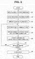
- FIG. 2 is a flowchart for explaining an example flow of the processing in the case where the TIC analysis is not performed.
- the ultrasound echo is transmitted and received by the ultrasound probe 2, and measurement is accordingly started.
- the mode is switched over to the contrast imaging mode (step S1), and recording of a normal movie is started (step S2) when operation of starting the movie recording is inputted through the input section 6.
- the volume data of the B-mode image is generated from the ultrasound echo that is received by the ultrasound probe 2, by the image processing section 5 (step S3). Note that the ultrasound power (the MI value) in acquisition of the volume data may be controlled to minimize destruction of the contrast agent.
- step S4 optimization of the scanning plane is performed by the first position correction section 12 (step S4).
- the correlation between the volume data and the reference image is calculated, the scanning plane having the highest correlation is set to the optimum scanning plane, and the image of the set scanning plane is continuously displayed.
- the scanning for contrast imaging mode is performed on the optimum scanning plane (step S5).
- the ultrasound echo to acquire the B-mode image and the contrast imaging mode image is transmitted only to the optimum scanning plane.
- the B-mode image and the contrast image are generated from the ultrasound echo by the image processing section 5 (step S6).
- step S7 it is determined whether operation of terminating the movie recording has been performed through the input section 6 (step S7).
- the process returns to step S4, and the similar process is repeated.
- step S7 the movie recording is terminated, the movie is stored (step S9), and the process is completed.
- FIG. 3 is a flowchart for explaining an example flow of the processing in the case where the TIC analysis is performed.
- the ultrasound probe 2 transmits and receives the ultrasound echo, thereby starting the measurement.
- the mode is switched over to the contrast imaging mode (step S11), and the reference image is set (step S12).
- the TIC analysis is performed, the image in which the region of interest, temporal variation of the contrast luminance of which is desired to be known, is clearly visualized is previously set by the reference image instruction section 10. Note that the process in step S12 may be performed in conjunction with the movie recording in step S13.
- the set reference image is stored in the reference image storage section 16.
- step S 13 When operation of starting the movie recording is inputted through the input section 6, recording of the movie is started (step S 13).
- the volume data of the B mode image is generated, by the image processing section 5, from the ultrasound echo that has been received by the ultrasound probe 2 (step S14). Note that the ultrasound power (the MI value) in acquisition of the volume data may be controlled in order to minimize destruction of the contrast agent.
- step S15 Optimization of the scanning plane is performed by the first position correction section 12 (step S15).
- the correlation between the volume data and the reference image is calculated, the scanning plane having the highest correlation is set to the optimum scanning plane, and the image of the set scanning plane is continuously displayed.
- the ultrasound echo to acquire the B-mode image and the contrast image is transmitted only to the optimum scanning plane (step S16).
- the ultrasound echo to be transmitted is applied with the ultrasound power (the MI value) that is the same as the ultrasound power in acquisition of the normal B-mode image and the contrast imaging mode image.
- the B-mode image and the contrast image are generated from the ultrasound echo by the image processing section 5 (step S17). It is determined whether the operation of terminating the movie recording has been performed through the input section 6 (step S18). When it is determined that the operation of terminating the movie recording has not been performed (No in step S18), the process returns to step S 15, and the similar process is repeated. On the other hand, when it is determined that the operation of terminating the movie recording has been performed (Yes in step S18), the movie recording is terminated and the movie is stored (step S 19).
- the recorded movie is read (step S20), and the ROI for TIC analysis is set to the region of interest from the read movie (step S21).
- the TIC analysis is started, and the positional deviation of the ROI for TIC analysis is automatically corrected by the second position correction section 13 (step S22).
- step S22 the contour of the region of interest in the scanning plane is extracted, and the position of the ROI for TIC analysis is automatically corrected in synchronization with the movement of the region of interest. Finally, the temporal variation of the contrast luminance in the ROI for TIC analysis is calculated, and the calculated temporal variation of the contrast luminance is displayed with, for example, a graph (step S23). Thus, the process is completed.
- Fig. 4 is a flowchart for explaining an example flow of the optimization process of the scanning plane in steps S4 and S 15.
- the scanning is performed in the first direction (step S32), and the B-mode image is generated by the B-mode image data generation section 17 (step S33).
- a correlation value between the generated B-mode image and the reference image held by the reference image storage section 16 is calculated by the correlation calculation section 14 (step S34).
- step S35 the scanning plane is moved, by the first position correction section 12, to a position having the highest calculated correlation value (step S37).
- step S37 the process in step S37 is competed and the optimum scanning plane is determined, the process returns to step S5 in Fig. 2 or step S16 in Fig. 3 , and the scanning is performed on the optimum scanning plane.
- the above-described processes make it possible to automatically correct the region of interest desired to be subjected to the TIC analysis according to the deviation of the region of interest.
- the volume data of the B-mode image generated by the B-mode image data generation section 17 is not stored in the movie storage section 15 and is used only for the position correction of the scanning plane.
- the ultrasound observation apparatus 1 makes it possible to three-dimensionally correct the deviation of the region of interest due to pulsation, hand shake, or other factors while suppressing the data capacity, which allows for accurate observation of the region of interest and accurate comprehension of the calculation results of TIC analysis.
- the ultrasound observation apparatus of the present embodiment allows for accurate comprehension of the temporal variation of the contrast luminance even if the probe is deviated from the region of interest, while suppressing the data capacity for the TIC analysis.
- Fig. 5 is a block diagram illustrating an entire configuration of an ultrasound observation apparatus according to a second embodiment. Note that, in Fig. 5 , components similar to components of Fig. 1 are denoted by the same reference numerals and description of the components is omitted.
- an ultrasound observation apparatus 1a includes an ultrasound probe 2a, a calculation section 4a, and a storage section 8a, in place of the ultrasound probe 2, the calculation section 4, and the storage section 8, respectively, of the ultrasound observation apparatus 1 in Fig. 1 .
- the ultrasound probe 2a is configured by adding a signal conversion section 21 and a sensor section 22 to the ultrasound probe 2 in Fig. 1 .
- a first position correction section 12a and a second position correction section 13a are provided in place of the first position correction section 12 and the second position correction section 13, respectively, of the calculation section 4 in Fig. 1 , and the correlation calculation section 14 in Fig. 1 is removed.
- the storage section 8a is configured by adding a positional information storage section 23 to the storage section 8 in Fig. 1 .
- the signal conversion section 21 converts the electric pulse signal that is received from the transmitting-receiving section 3, into the ultrasound pulse, and converts the ultrasound echo that is reflected by the outside subject, into the electric echo signal again.
- the sensor section 22 may be configured of, for example, a gyro sensor or a magnetic sensor, and detects information of the position and the direction of the ultrasound probe 2a.
- the information of the position and the direction of the ultrasound probe 2a detected by the sensor section 22 is provided to the storage section 8a through the control section 9.
- the positional information storage section 23 of the storage section 8a holds positional information in acquisition of the reference image, and holds the information of the position and the direction of the ultrasound probe 2a detected by the sensor section 22 as needed.
- the first position correction section 12a corrects deviation of the scanning plane with respect to movement of the region of interest for TIC analysis. At this time, the first position correction section 12a moves the scanning plane based on the information of the position and the direction of the ultrasound probe 2a that is held by the positional information storage section 23.
- the second position correction section 13a automatically corrects the position of the ROI for TIC analysis in synchronization with the movement of the region of interest in the scanning plane. At this time, the second position correction section 13a automatically corrects the position of the ROI in the scanning plane, based on the information of the position and the direction of the ultrasound probe 2a that is held by the positional information storage section 23.
- the other components are similar to components of the first embodiment.
- the optimization process of the scanning plane in step S4 of Fig. 2 and in step S 15 of Fig. 3 is different from that of the first embodiment.
- the position and the direction of the ultrasound probe 2a are acquired by the sensor section 22 provided in the ultrasound probe 2a.
- the first position correction section 12a detects movement degree and a movement direction of the reference image, from the acquired position and the acquired direction of the ultrasound probe 2, thereby correcting the scanning plane from the volume data, based on the detected information, to continuously display the reference image.
- the process of automatically correcting the ROI for TIC analysis in step S22 of Fig. 3 is different from process of the first embodiment.
- the information of the position and the direction that is detected by the sensor section 22 provided in the ultrasound probe 2a is read out from the positional information storage section 23, and the second position correction section 13a automatically corrects the position of the ROI for TIC analysis, based on the read information of the position and the direction.
- Other processes are similar to processes in Fig. 2 to Fig. 4 .
- Fig. 6A to Fig. 6C are diagrams for explaining the automatic correction of the position of the ROI for TIC analysis.
- the ROI for TIC analysis is set to a region of interest in the scanning plane. If the position or the direction of the probe is deviated due to hand shake or other factors, the region of interest is deviated to the outside of the ROI for TIC analysis, as illustrated in Fig. 6B .
- the second position correction section 13a automatically corrects the position of the ROI for TIC analysis, based on the information of the position and the direction of the ultrasound probe 2a that is detected by the sensor section 22 and is held by the positional information storage section 23.
- the ultrasound observation apparatus 1a according to the present embodiment is different in the method of optimizing the scanning plane and the method of automatically correcting the position of the ROI for TIC analysis from the first embodiment.
- the sensor section 22 is provided in the ultrasound probe 2a to acquire the information of the position and the direction of the ultrasound probe 2a, and the scanning plane is optimized and the position of the ROI for TIC analysis is automatically corrected based on the information.
- the ultrasound observation apparatus 1a of the present embodiment allows for accurate comprehension of the temporal variation of the contrast luminance even if the probe is deviated from the region of interest, while suppressing the data capacity for the TIC analysis, as with the first embodiment.
- the display section 7 displays the various kinds of information including the image generated by the image processing section 5.
- the image displayed on the display section 7 is a live image that is being observed.
- An image that has the highest correlation value with the reference image (the movie for TIC analysis) is stored in the apparatus (for example, stored in the movie storage section 15), and is read out and used in the TIC analysis.
- Other components are similar to components of the first or second embodiment.
- the display section 7 displays the various kinds of information including the image generated by the image processing section 5.
- the image displayed on the display section 7 is an image (a movie for TIC analysis) that has the highest correlation value with the reference image, calculated by the correlation calculation section 14.
- the display section 7 may display the image that has the highest correlation value with the reference image and the live image being observed at a time. At this time, only the image that has the highest correlation value with the reference image by the correlation calculation section 14 is stored in the apparatus as the movie for TIC analysis.
- Other components are similar to components of the first or second embodiment.
- the volume data of the B-mode image that is generated for the correlation calculation by the B-mode image data generation section 17 may be displayed on the display section 7, together with the image that has the highest correlation value with the reference image and/or the live image being observed, at a time.
Landscapes
- Health & Medical Sciences (AREA)
- Life Sciences & Earth Sciences (AREA)
- Engineering & Computer Science (AREA)
- Biomedical Technology (AREA)
- Medical Informatics (AREA)
- Pathology (AREA)
- Radiology & Medical Imaging (AREA)
- Biophysics (AREA)
- Physics & Mathematics (AREA)
- Heart & Thoracic Surgery (AREA)
- Nuclear Medicine, Radiotherapy & Molecular Imaging (AREA)
- Molecular Biology (AREA)
- Surgery (AREA)
- Animal Behavior & Ethology (AREA)
- General Health & Medical Sciences (AREA)
- Public Health (AREA)
- Veterinary Medicine (AREA)
- Computer Vision & Pattern Recognition (AREA)
- Ultra Sonic Daignosis Equipment (AREA)
Description
- The present invention relates to an ultrasound observation apparatus, and in particular, to an ultrasound observation apparatus that can calculate temporal variation of luminance in a region of interest.
- An ultrasound observation apparatus has been widely used in a medical field or other fields. The ultrasound observation apparatus transmits and receives ultrasound to/from a subject to generate an ultrasound image that indicates acoustic characteristics inside the subject, and uses the ultrasound image in inspection and diagnosis of the subject.
- The ultrasound observation apparatus used in the medical field or other fields includes an ultrasound probe that is capable of transmitting and receiving ultrasound to/from the subject, and generates a B-mode image that is a cross-sectional image of the subject. The B-mode image is obtained through scanning of a predetermined scanning plane with an ultrasound beam.
- For example, Japanese Patent No.
4801229 - Also, such an ultrasound observation apparatus uses TIC (time intensity curve) analysis as an objective diagnostic approach using an ultrasound contrast agent. In the TIC analysis, a region of interest (ROI) for TIC analysis is set to a region of interest in the scanning plane, and temporal variation of contrast luminance in the ROI is calculated.
- For example, Japanese Patent Application Laid-Open Publication No.
2011-254963 - In the existing TIC analysis, however, if the position or the direction of the probe is deviated by hand shake or other factors, the region of interest in the scanning plane is deviated to the outside of the set ROI. Thus, it is disadvantageously difficult to accurately comprehend (evaluate) the temporal variation of the contrast luminance in the region of interest.
- The technology disclosed in Japanese Patent No.
4801229 2011-254963 - To perform the TIC analysis, however, it is necessary to store the volume data (movies) acquired for each case. This disadvantageously increases data capacity.
- Therefore, it is an object of the present invention to provide an ultrasound observation apparatus that allows for accurate comprehension of temporal variation of contrast luminance even if the probe is deviated from the region of interest, while suppressing data capacity for the TIC analysis.
- An ultrasound observation apparatus according to an aspect of the present invention sets a second region of interest for analysis of temporal variation of luminance to a first region of interest and calculates temporal variation of luminance in the second region of interest. The ultrasound observation apparatus includes: an ultrasound probe configured to change a transmitting-receiving direction of ultrasound in a first direction and a second direction to perform two-dimensional scanning with an ultrasound beam; a transmitting-receiving section configured to control the transmitting-receiving direction of the ultrasound beam of the ultrasound probe; an image processing section configured to generate volume data of a B-mode image from a result of scanning with the ultrasound beam in the first direction and the second direction; an input section configured to set, as a reference image, an image in which the first region of interest is clearly visualized; a storage section configured to hold the reference image; and a calculation section configured to correct a scanning plane to allow an image similar to the reference image that is set by the input section, to be constantly displayed. The calculation section automatically corrects a position of the second region of interest for analysis of temporal variation of luminance, in synchronization with movement of the first region of interest in the scanning plane.
-
-
Fig. 1 is a block diagram illustrating an entire configuration of an ultrasound observation apparatus according to a first embodiment; -
Fig. 2 is a flowchart for explaining an example flow of processing in a case where TIC analysis is not performed; -
Fig. 3 is a flowchart for explaining an example flow of processing in a case where TIC analysis is performed; -
Fig. 4 is a flowchart for explaining an example flow of optimization process of a scanning plane in steps S4 and S15; -
Fig. 5 is a block diagram illustrating an entire configuration of an ultrasound observation apparatus according to a second embodiment; -
Fig. 6A is a diagram for explaining automatic correction of a position of a ROI for TIC analysis; -
Fig. 6B is a diagram for explaining the automatic correction of the position of the ROI for TIC analysis; and -
Fig. 6C is a diagram for explaining the automatic correction of the position of the ROI for TIC analysis. - Hereinafter, embodiments of the present invention are described with reference to drawings.
- First, a configuration of an ultrasound observation apparatus according to a first embodiment is described with reference to
Fig. 1. Fig. 1 is a block diagram illustrating an entire configuration of an ultrasound observation apparatus according to the first embodiment. Anultrasound observation apparatus 1 illustrated inFig. 1 is an apparatus used to observe a subject with use of ultrasound. - The
ultrasound observation apparatus 1 includes: anultrasound probe 2 that outputs an ultrasound pulse to the subject and receives an ultrasound echo reflected by the subject; a transmitting-receivingsection 3 that transmits and receives an electric signal to/from theultrasound probe 2; acalculation section 4 that performs predetermined calculation on an electric echo signal that is converted from the ultrasound echo; animage processing section 5 that generates image data corresponding to the electric echo signal converted from the ultrasound echo; aninput section 6 that is configured of interfaces such as a keyboard, a mouse, and a touch panel, and receives input of various kinds of information; a display section 7 that is configured of a display panel formed of a liquid crystal, an organic EL or the like, and displays various kinds of information including the image that is generated by theimage processing section 5; astorage section 8 that holds various kinds of information including an image and a movie acquired from the subject; and acontrol section 9 that controls entire operation of theultrasound observation apparatus 1. - The
ultrasound probe 2 is configured to perform two-dimensional scanning with an ultrasound beam by changing a transmitting-receiving direction in a first direction and a second direction with use of an ultrasound transducers that are two-dimensionally arranged. Theultrasound probe 2 converts an electric pulse signal received from the transmitting-receivingsection 3, into an ultrasound pulse, and converts an ultrasound echo that is reflected by an outside subject, into an electric echo signal again. - The transmitting-receiving
section 3 is electrically connected with theultrasound probe 2, and transmits the pulse signal to theultrasound probe 2 and receives the echo signal from theultrasound probe 2. More specifically, the transmitting-receivingsection 3 generates the pulse signal based on a preset waveform and preset transmission timing, and transmits the generated pulse signal to theultrasound probe 2. Also, the transmitting-receivingsection 3 performs processing such as amplification and filtering on the received echo signal, and then performs A/D conversion, thereby generating a digital signal to provide the digital signal to thecontrol section 9. - The
input section 6 includes a referenceimage instruction section 10 that sets, as a reference image, an image in which a region of interest is clearly visualized, in order to perform TIC (time intensity curve) analysis. The reference image is previously fabricated by a user according to the size of the region of interest, clarity of a contour of the region of interest, and the like. Note that the setting of the reference image is not limited to the referenceimage instruction section 10, and for example, a reference image setting button may be provided, or the setting of the reference image may be linked to an unillustrated movie recording button. - The
image processing section 5 includes: a B-mode imagedata generation section 17 that generates B-mode image data; and a contrast imagedata generation section 18 that generates contrast image data with use of a signal reflected by a contrast agent flowing into the subject. The B-mode image data displays luminance that is converted from an amplitude of the echo signal. - The data generated by the B-mode image
data generation section 17 is volume data. Note that ultrasound power (an MI value) in acquisition of the volume data may be controlled to minimize destruction of the contrast agent. - The
storage section 8 includes: amovie storage section 15 that holds the contrast image data (a movie); and a referenceimage storage section 16 that holds the reference image set by the referenceimage instruction section 10. The contrast image data is acquired with use of a signal from the contrast agent that is administered to and flows into the subject. - The
movie storage section 15 holds a movie of an optional plane of the volume data in which the region of interest is displayed, in order to suppress data capacity. The volume data of the B-mode image generated by the B-mode imagedata generation section 17 is not stored in themovie storage section 15 and is used only for calculation to correct the position of the scanning plane. - The
calculation section 4 includes: aTIC analysis section 11 that performs TIC analysis; a firstposition correction section 12 that corrects deviation of the scanning plane with respect to movement of the region of interest for TIC analysis; a secondposition correction section 13 that performs contour extraction of the region of interest in the scanning plane to automatically correct the position of a ROI for the TIC analysis, in synchronization with the movement of the region of interest in the scanning plane; and acorrelation calculation section 14 that calculates a correlation value between the volume data of the B-mode image generated by the B-mode imagedata generation section 17 and the reference image held by the referenceimage storage section 16. - The first
position correction section 12 calculates the correlation between the acquired volume data and the reference image, and moves the scanning plane in the second direction of the transmitting-receivingsection 3 in order to display, on the display section 7, the scanning plane having the largest correlation value. More specifically, the firstposition correction section 12 corrects the scanning plane such that an image similar to the reference image set by theinput section 6 is constantly displayed. A method of determining the optimum scanning plane is described later. - To calculate the correlation between the acquired volume data and the reference image, image processing so-called pattern matching is performed on the generated B-mode image with use of the reference image as a template, and calculates similarity between the echo pattern in the B-mode image and the reference image. The image processing may be, for example, pattern matching of the contour of the region of interest, or pattern matching of adjacent organs displayed on the image. The correlation value becomes high as the similarity between the echo pattern in the B-mode image and the reference image is higher. Note that the detailed description of the pattern matching is omitted because the pattern matching is a well-known technology.
- Note that, when the ultrasound power (the MI value) is suppressed in order to minimize destruction of the contrast agent in acquisition of the volume data, the ultrasound is applied to the optimum plane (the scanning plane having the largest correlation) with the ultrasound power that is the same as the ultrasound power in acquisition of the normal B-mode image and the contrast imaging mode image.
- The second
position correction section 13 uses, as the template, the region of interest in the scanning plane image determined by the firstposition correction section 12, and uses the above-described pattern matching processing, thereby automatically correcting the position of the ROI for TIC analysis, in synchronization with the movement of the region of interest. - Next, operation of the
ultrasound observation apparatus 1 having the above-described configuration is described. First, the operation in a case where the TIC analysis is not performed is described.Fig. 2 is a flowchart for explaining an example flow of the processing in the case where the TIC analysis is not performed. - When operation of releasing a frozen state is inputted through the
input section 6, the ultrasound echo is transmitted and received by theultrasound probe 2, and measurement is accordingly started. First, the mode is switched over to the contrast imaging mode (step S1), and recording of a normal movie is started (step S2) when operation of starting the movie recording is inputted through theinput section 6. - The volume data of the B-mode image is generated from the ultrasound echo that is received by the
ultrasound probe 2, by the image processing section 5 (step S3). Note that the ultrasound power (the MI value) in acquisition of the volume data may be controlled to minimize destruction of the contrast agent. - Next, optimization of the scanning plane is performed by the first position correction section 12 (step S4). In the process in step S4, the correlation between the volume data and the reference image is calculated, the scanning plane having the highest correlation is set to the optimum scanning plane, and the image of the set scanning plane is continuously displayed.
- The scanning for contrast imaging mode is performed on the optimum scanning plane (step S5). In other words, in the process in step S5, the ultrasound echo to acquire the B-mode image and the contrast imaging mode image is transmitted only to the optimum scanning plane. Next, the B-mode image and the contrast image are generated from the ultrasound echo by the image processing section 5 (step S6).
- Next, it is determined whether operation of terminating the movie recording has been performed through the input section 6 (step S7). When it is determined that the operation of terminating the movie recording has not been performed (No in step S7), the process returns to step S4, and the similar process is repeated. On the other hand, when it is determined that the operation of terminating the movie recording has been performed (Yes in step S7), the movie recording is terminated, the movie is stored (step S9), and the process is completed.
- Next, the operation in a case where the TIC analysis is performed is described.
Fig. 3 is a flowchart for explaining an example flow of the processing in the case where the TIC analysis is performed. - When the operation of releasing the frozen state is inputted through the
input section 6, theultrasound probe 2 transmits and receives the ultrasound echo, thereby starting the measurement. First, the mode is switched over to the contrast imaging mode (step S11), and the reference image is set (step S12). When the TIC analysis is performed, the image in which the region of interest, temporal variation of the contrast luminance of which is desired to be known, is clearly visualized is previously set by the referenceimage instruction section 10. Note that the process in step S12 may be performed in conjunction with the movie recording in step S13. The set reference image is stored in the referenceimage storage section 16. - When operation of starting the movie recording is inputted through the
input section 6, recording of the movie is started (step S 13). The volume data of the B mode image is generated, by theimage processing section 5, from the ultrasound echo that has been received by the ultrasound probe 2 (step S14). Note that the ultrasound power (the MI value) in acquisition of the volume data may be controlled in order to minimize destruction of the contrast agent. - Optimization of the scanning plane is performed by the first position correction section 12 (step S15). In the process in step S15, the correlation between the volume data and the reference image is calculated, the scanning plane having the highest correlation is set to the optimum scanning plane, and the image of the set scanning plane is continuously displayed.
- The ultrasound echo to acquire the B-mode image and the contrast image is transmitted only to the optimum scanning plane (step S16). The ultrasound echo to be transmitted is applied with the ultrasound power (the MI value) that is the same as the ultrasound power in acquisition of the normal B-mode image and the contrast imaging mode image.
- The B-mode image and the contrast image are generated from the ultrasound echo by the image processing section 5 (step S17). It is determined whether the operation of terminating the movie recording has been performed through the input section 6 (step S18). When it is determined that the operation of terminating the movie recording has not been performed (No in step S18), the process returns to step
S 15, and the similar process is repeated. On the other hand, when it is determined that the operation of terminating the movie recording has been performed (Yes in step S18), the movie recording is terminated and the movie is stored (step S 19). - Next, when the TIC analysis is performed, the recorded movie is read (step S20), and the ROI for TIC analysis is set to the region of interest from the read movie (step S21). When the operation of starting the TIC analysis is inputted through the
input section 6, the TIC analysis is started, and the positional deviation of the ROI for TIC analysis is automatically corrected by the second position correction section 13 (step S22). - In the process in step S22, the contour of the region of interest in the scanning plane is extracted, and the position of the ROI for TIC analysis is automatically corrected in synchronization with the movement of the region of interest. Finally, the temporal variation of the contrast luminance in the ROI for TIC analysis is calculated, and the calculated temporal variation of the contrast luminance is displayed with, for example, a graph (step S23). Thus, the process is completed.
- Here, the optimization process of the scanning plane in steps S4 and
S 15 is described with reference toFig. 4. Fig. 4 is a flowchart for explaining an example flow of the optimization process of the scanning plane in steps S4 andS 15. - First, the scanning plane is set to one end (N = 1) of the scanning range in a second direction of the ultrasound probe 2 (step S31). Next, the scanning is performed in the first direction (step S32), and the B-mode image is generated by the B-mode image data generation section 17 (step S33). Next, a correlation value between the generated B-mode image and the reference image held by the reference
image storage section 16 is calculated by the correlation calculation section 14 (step S34). - Next, it is determined whether the scanning range has been scanned at all positions (N = Nmax) in the second direction (step S35). When the scanning range has not been scanned at all positions (N = Nmax) in the second direction (No in step S35), the scanning plane is moved toward the other end in the second direction of the
ultrasound probe 2 by a predetermined value (N = N+1) and set (step S36). Then, the process returns to step S32, and the similar process is repeated to calculate the correlation value between the B-mode image and the reference image. - These processes are repeated until scanning of the scanning range at all positions (N = Nmax) in the second direction is completed. When it is determined that the scanning range has been scanned at all positions (N = Nmax) in the second direction (Yes in step S35), the scanning plane is moved, by the first
position correction section 12, to a position having the highest calculated correlation value (step S37). When the process in step S37 is competed and the optimum scanning plane is determined, the process returns to step S5 inFig. 2 or step S16 inFig. 3 , and the scanning is performed on the optimum scanning plane. - Even if the region of interest is deviated, due to pulsation, hand shake, or other factors, from the region of interest desired to be subjected to the TIC analysis, the above-described processes make it possible to automatically correct the region of interest desired to be subjected to the TIC analysis according to the deviation of the region of interest. In addition, the volume data of the B-mode image generated by the B-mode image
data generation section 17 is not stored in themovie storage section 15 and is used only for the position correction of the scanning plane. As a result, theultrasound observation apparatus 1 makes it possible to three-dimensionally correct the deviation of the region of interest due to pulsation, hand shake, or other factors while suppressing the data capacity, which allows for accurate observation of the region of interest and accurate comprehension of the calculation results of TIC analysis. - Therefore, the ultrasound observation apparatus of the present embodiment allows for accurate comprehension of the temporal variation of the contrast luminance even if the probe is deviated from the region of interest, while suppressing the data capacity for the TIC analysis.
- Next, a second embodiment is described.
-
Fig. 5 is a block diagram illustrating an entire configuration of an ultrasound observation apparatus according to a second embodiment. Note that, inFig. 5 , components similar to components ofFig. 1 are denoted by the same reference numerals and description of the components is omitted. - As illustrated in
Fig. 5 , anultrasound observation apparatus 1a includes anultrasound probe 2a, acalculation section 4a, and astorage section 8a, in place of theultrasound probe 2, thecalculation section 4, and thestorage section 8, respectively, of theultrasound observation apparatus 1 inFig. 1 . - The
ultrasound probe 2a is configured by adding asignal conversion section 21 and asensor section 22 to theultrasound probe 2 inFig. 1 . Also, in thecalculation section 4a, a firstposition correction section 12a and a secondposition correction section 13a are provided in place of the firstposition correction section 12 and the secondposition correction section 13, respectively, of thecalculation section 4 inFig. 1 , and thecorrelation calculation section 14 inFig. 1 is removed. Further, thestorage section 8a is configured by adding a positionalinformation storage section 23 to thestorage section 8 inFig. 1 . - The
signal conversion section 21 converts the electric pulse signal that is received from the transmitting-receivingsection 3, into the ultrasound pulse, and converts the ultrasound echo that is reflected by the outside subject, into the electric echo signal again. - The
sensor section 22 may be configured of, for example, a gyro sensor or a magnetic sensor, and detects information of the position and the direction of theultrasound probe 2a. The information of the position and the direction of theultrasound probe 2a detected by thesensor section 22 is provided to thestorage section 8a through thecontrol section 9. - The positional
information storage section 23 of thestorage section 8a holds positional information in acquisition of the reference image, and holds the information of the position and the direction of theultrasound probe 2a detected by thesensor section 22 as needed. - The first
position correction section 12a corrects deviation of the scanning plane with respect to movement of the region of interest for TIC analysis. At this time, the firstposition correction section 12a moves the scanning plane based on the information of the position and the direction of theultrasound probe 2a that is held by the positionalinformation storage section 23. - Also, the second
position correction section 13a automatically corrects the position of the ROI for TIC analysis in synchronization with the movement of the region of interest in the scanning plane. At this time, the secondposition correction section 13a automatically corrects the position of the ROI in the scanning plane, based on the information of the position and the direction of theultrasound probe 2a that is held by the positionalinformation storage section 23. The other components are similar to components of the first embodiment. - Next, the operation of the
ultrasound observation apparatus 1a having such a configuration is described. The process when the TIC analysis is not performed and the process when the TIC analysis is performed are substantially similar to those inFig. 2 to Fig. 4 , and only different processes are described. - In the second embodiment, the optimization process of the scanning plane in step S4 of
Fig. 2 and in step S 15 ofFig. 3 is different from that of the first embodiment. In the second embodiment, the position and the direction of theultrasound probe 2a are acquired by thesensor section 22 provided in theultrasound probe 2a. Then, the firstposition correction section 12a detects movement degree and a movement direction of the reference image, from the acquired position and the acquired direction of theultrasound probe 2, thereby correcting the scanning plane from the volume data, based on the detected information, to continuously display the reference image. - Also, in the second embodiment, the process of automatically correcting the ROI for TIC analysis in step S22 of
Fig. 3 is different from process of the first embodiment. In the second embodiment, the information of the position and the direction that is detected by thesensor section 22 provided in theultrasound probe 2a is read out from the positionalinformation storage section 23, and the secondposition correction section 13a automatically corrects the position of the ROI for TIC analysis, based on the read information of the position and the direction. Other processes are similar to processes inFig. 2 to Fig. 4 . - Here, the automatic correction of the position of the ROI for TIC analysis is described with reference to
Fig. 6A to Fig. 6C. Fig. 6A to Fig. 6C are diagrams for explaining the automatic correction of the position of the ROI for TIC analysis. - First, as illustrated in
Fig. 6A , the ROI for TIC analysis is set to a region of interest in the scanning plane. If the position or the direction of the probe is deviated due to hand shake or other factors, the region of interest is deviated to the outside of the ROI for TIC analysis, as illustrated inFig. 6B . - In this case, as illustrated in
Fig. 6C , the secondposition correction section 13a automatically corrects the position of the ROI for TIC analysis, based on the information of the position and the direction of theultrasound probe 2a that is detected by thesensor section 22 and is held by the positionalinformation storage section 23. - As mentioned above, the
ultrasound observation apparatus 1a according to the present embodiment is different in the method of optimizing the scanning plane and the method of automatically correcting the position of the ROI for TIC analysis from the first embodiment. In theultrasound observation apparatus 1a according to the present embodiment, thesensor section 22 is provided in theultrasound probe 2a to acquire the information of the position and the direction of theultrasound probe 2a, and the scanning plane is optimized and the position of the ROI for TIC analysis is automatically corrected based on the information. - Other components and operation are similar to the components and the operation of the first embodiment. Therefore, the
ultrasound observation apparatus 1a of the present embodiment allows for accurate comprehension of the temporal variation of the contrast luminance even if the probe is deviated from the region of interest, while suppressing the data capacity for the TIC analysis, as with the first embodiment. - Next, a third embodiment is described.
- The display section 7 displays the various kinds of information including the image generated by the
image processing section 5. The image displayed on the display section 7 is a live image that is being observed. An image that has the highest correlation value with the reference image (the movie for TIC analysis) is stored in the apparatus (for example, stored in the movie storage section 15), and is read out and used in the TIC analysis. Other components are similar to components of the first or second embodiment. - Next, a fourth embodiment is described.
- The display section 7 displays the various kinds of information including the image generated by the
image processing section 5. The image displayed on the display section 7 is an image (a movie for TIC analysis) that has the highest correlation value with the reference image, calculated by thecorrelation calculation section 14. Note that the display section 7 may display the image that has the highest correlation value with the reference image and the live image being observed at a time. At this time, only the image that has the highest correlation value with the reference image by thecorrelation calculation section 14 is stored in the apparatus as the movie for TIC analysis. Other components are similar to components of the first or second embodiment. - Note that in the third embodiment and the fourth embodiment, the volume data of the B-mode image that is generated for the correlation calculation by the B-mode image
data generation section 17 may be displayed on the display section 7, together with the image that has the highest correlation value with the reference image and/or the live image being observed, at a time. - Note that the respective steps in the respective flowcharts in the present specification may be changed in execution order, executed together at a time, or executed in different order in each execution, unless contrary to the nature of the steps.
- The present invention is not limited to the above-described embodiments, and other various modifications and alternations may occur within the scope of the present invention.
- The present application is based upon and claims the benefit of priority of Japanese Patent Application No.
2014-211786
Claims (7)
- An ultrasound observation apparatus that sets a second region of interest for analysis of temporal variation of luminance to a first region of interest and calculates temporal variation of luminance in the second region of interest, the ultrasound observation apparatus comprising:an ultrasound probe configured to change a transmitting-receiving direction of ultrasound in a first direction and a second direction to perform two-dimensional scanning with an ultrasound beam;a transmitting-receiving section configured to control the transmitting-receiving direction of the ultrasound beam of the ultrasound probe;an image processing section configured to generate volume data of a B-mode image from a result of scanning with the ultrasound beam in the first direction and the second direction;an input section configured to set, as a reference image, an image in which the first region of interest is clearly visualized;a storage section configured to hold the reference image; anda calculation section configured to correct a scanning plane to allow an image similar to the reference image that is set by the input section, to be constantly displayed, whereinthe calculation section automatically corrects a position of the second region of interest for analysis of temporal variation of luminance, in synchronization with movement of the first region of interest in the scanning plane.
- The ultrasound observation apparatus according to claim 1, wherein
the calculation section calculates a correlation value between the volume data and the reference image held by the storage section, and
the transmitting-receiving section moves the scanning plane in the second direction to maximize the correlation value. - The ultrasound observation apparatus according to claim 1, further comprising a TIC analysis section configured to calculate temporal variation of contrast luminance in the second region of interest that is set to the first region of interest, wherein
the calculation section automatically corrects the position of the second region of interest for TIC analysis, in synchronization with the movement of the first region of interest. - The ultrasound observation apparatus according to claim 1, wherein the calculation section performs contour extraction of the first region of interest to automatically correct the position of the second region of interest, in synchronization with the movement of the first region of interest.
- The ultrasound observation apparatus according to claim 1, wherein
the ultrasound probe includes a sensor that detects a position and a direction of the ultrasound probe,
the storage section holds information of the position and the direction detected by the sensor, and
the calculation section corrects, based on the information of the position and the direction, the scanning plane to allow the reference image held by the storage section to be constantly displayed. - The ultrasound observation apparatus according to claim 5, wherein the calculation section reads, from the storage section, the information of the position and the direction detected by the sensor, and automatically corrects the position of the second region of interest, based on the read information of the position and the direction.
- The ultrasound observation apparatus according to claim 5, wherein the sensor is a gyro sensor or a magnetic sensor.
Applications Claiming Priority (2)
| Application Number | Priority Date | Filing Date | Title |
|---|---|---|---|
| JP2014211786 | 2014-10-16 | ||
| PCT/JP2015/075328 WO2016059913A1 (en) | 2014-10-16 | 2015-09-07 | Ultrasonic observation apparatus |
Publications (3)
| Publication Number | Publication Date |
|---|---|
| EP3165172A1 true EP3165172A1 (en) | 2017-05-10 |
| EP3165172A4 EP3165172A4 (en) | 2018-03-21 |
| EP3165172B1 EP3165172B1 (en) | 2019-06-12 |
Family
ID=55746461
Family Applications (1)
| Application Number | Title | Priority Date | Filing Date |
|---|---|---|---|
| EP15851011.5A Active EP3165172B1 (en) | 2014-10-16 | 2015-09-07 | Ultrasound observation apparatus |
Country Status (5)
| Country | Link |
|---|---|
| US (1) | US9918697B2 (en) |
| EP (1) | EP3165172B1 (en) |
| JP (1) | JP5974200B1 (en) |
| CN (1) | CN106170254B (en) |
| WO (1) | WO2016059913A1 (en) |
Families Citing this family (3)
| Publication number | Priority date | Publication date | Assignee | Title |
|---|---|---|---|---|
| JP6850140B2 (en) * | 2017-01-31 | 2021-03-31 | ゼネラル・エレクトリック・カンパニイ | Ultrasonic diagnostic equipment and its control program |
| JP2021515667A (en) * | 2018-03-16 | 2021-06-24 | エコーノース インコーポレーテッドEchoNous, Inc. | Systems and methods for motion-based control of ultrasound images |
| US12561800B2 (en) * | 2022-12-30 | 2026-02-24 | GE Precision Healthcare LLC | Super resolution for electronic 4D (E4D) cardiovascular ultrasound (CVUS) probes |
Family Cites Families (11)
| Publication number | Priority date | Publication date | Assignee | Title |
|---|---|---|---|---|
| JP2003061959A (en) | 2001-08-22 | 2003-03-04 | Toshiba Corp | Ultrasound diagnostic equipment |
| WO2007080895A1 (en) | 2006-01-10 | 2007-07-19 | Kabushiki Kaisha Toshiba | Ultrasonograph and ultrasonogram creating method |
| JP5209213B2 (en) * | 2006-01-10 | 2013-06-12 | 株式会社東芝 | Ultrasonic diagnostic apparatus and ultrasonic image generation program |
| CN101945615B (en) * | 2008-03-07 | 2014-01-29 | 株式会社日立医疗器械 | Ultrasonic imaging apparatus |
| WO2010117025A1 (en) * | 2009-04-10 | 2010-10-14 | 株式会社 日立メディコ | Ultrasonic diagnosis apparatus and method for constructing distribution image of blood flow dynamic state |
| JP4801229B2 (en) | 2009-11-16 | 2011-10-26 | オリンパスメディカルシステムズ株式会社 | Ultrasonic observation apparatus and control method of ultrasonic observation apparatus |
| US9066674B2 (en) | 2010-03-17 | 2015-06-30 | Siemens Medical Solutions Usa, Inc. | Motion synchronized destruction for three-dimensional reperfusion mapping in medical diagnostic ultrasound imaging |
| JP5632203B2 (en) | 2010-06-08 | 2014-11-26 | 株式会社東芝 | Ultrasonic diagnostic apparatus, ultrasonic image processing apparatus, and ultrasonic image processing program |
| CN102573652A (en) * | 2010-08-11 | 2012-07-11 | 株式会社东芝 | Medical image diagnosis device, image-processing device and method |
| JP2013081764A (en) | 2011-09-27 | 2013-05-09 | Toshiba Corp | Ultrasonic diagnostic apparatus and ultrasonic scanning method |
| WO2014034948A1 (en) * | 2012-09-03 | 2014-03-06 | 株式会社東芝 | Ultrasonic diagnostic apparatus and image processing method |
-
2015
- 2015-09-07 EP EP15851011.5A patent/EP3165172B1/en active Active
- 2015-09-07 CN CN201580019346.9A patent/CN106170254B/en active Active
- 2015-09-07 JP JP2016501479A patent/JP5974200B1/en active Active
- 2015-09-07 WO PCT/JP2015/075328 patent/WO2016059913A1/en not_active Ceased
-
2017
- 2017-02-02 US US15/422,616 patent/US9918697B2/en active Active
Also Published As
| Publication number | Publication date |
|---|---|
| EP3165172A4 (en) | 2018-03-21 |
| EP3165172B1 (en) | 2019-06-12 |
| US20170143301A1 (en) | 2017-05-25 |
| CN106170254B (en) | 2019-03-26 |
| WO2016059913A1 (en) | 2016-04-21 |
| CN106170254A (en) | 2016-11-30 |
| US9918697B2 (en) | 2018-03-20 |
| JP5974200B1 (en) | 2016-08-23 |
| JPWO2016059913A1 (en) | 2017-04-27 |
Similar Documents
| Publication | Publication Date | Title |
|---|---|---|
| KR102917269B1 (en) | Ultrasound diagnosis apparatus and mehtod thereof | |
| JP6390145B2 (en) | Ultrasonic diagnostic imaging apparatus and method of operating ultrasonic diagnostic imaging apparatus | |
| US9161741B2 (en) | Ultrasonic image processing apparatus, ultrasonic diagnostic apparatus, and ultrasonic image processing method | |
| US20190200962A1 (en) | Ultrasound imaging apparatus and control method thereof | |
| CN102300505A (en) | Ultrasonic diagnostic apparatus and control program for image data display | |
| US20140039304A9 (en) | Ultrasound diagnostic apparatus and method | |
| US20160174932A1 (en) | Ultrasonic diagnostic device and ultrasonic image generation method | |
| US20240099688A1 (en) | Ultrasound diagnostic apparatus and control method for ultrasound diagnostic apparatus | |
| JP2015154883A (en) | Ultrasonic measurement device and ultrasonic measurement method | |
| JP6043028B1 (en) | Ultrasonic observation system | |
| US9918697B2 (en) | Ultrasound observation apparatus | |
| KR102336172B1 (en) | Ultrasound imaging device and method for controlling the same | |
| CN107440720A (en) | The bearing calibration of diagnostic ultrasound equipment and view data | |
| JP6279203B2 (en) | Ultrasonic diagnostic apparatus and control method of ultrasonic diagnostic apparatus | |
| EP3020339A1 (en) | Ultrasound observation apparatus, ultrasound observation system, and method for operating ultrasound observation apparatus | |
| US9872668B2 (en) | Medical diagnostic apparatus, method for operating medical diagnostic apparatus, and computer-readable recording medium | |
| JP2009261520A (en) | Ultrasonic imaging system | |
| EP4356844B1 (en) | ULTRASOUND DIAGNOSTIC DEVICE AND CONTROL METHOD FOR THE ULTRASOUND DIAGNOSTIC DEVICE | |
| JP2008289548A (en) | Ultrasonic diagnostic apparatus and diagnostic parameter measuring apparatus | |
| EP3158939B1 (en) | Ultrasonic apparatus and method for controlling the same | |
| KR102270721B1 (en) | Method and apparatus for generating ultrasonic image | |
| KR102565499B1 (en) | Ultrasonic apparatus, and control method for the same |
Legal Events
| Date | Code | Title | Description |
|---|---|---|---|
| STAA | Information on the status of an ep patent application or granted ep patent |
Free format text: STATUS: THE INTERNATIONAL PUBLICATION HAS BEEN MADE |
|
| PUAI | Public reference made under article 153(3) epc to a published international application that has entered the european phase |
Free format text: ORIGINAL CODE: 0009012 |
|
| STAA | Information on the status of an ep patent application or granted ep patent |
Free format text: STATUS: REQUEST FOR EXAMINATION WAS MADE |
|
| 17P | Request for examination filed |
Effective date: 20170131 |
|
| AK | Designated contracting states |
Kind code of ref document: A1 Designated state(s): AL AT BE BG CH CY CZ DE DK EE ES FI FR GB GR HR HU IE IS IT LI LT LU LV MC MK MT NL NO PL PT RO RS SE SI SK SM TR |
|
| AX | Request for extension of the european patent |
Extension state: BA ME |
|
| DAV | Request for validation of the european patent (deleted) | ||
| DAX | Request for extension of the european patent (deleted) | ||
| A4 | Supplementary search report drawn up and despatched |
Effective date: 20180216 |
|
| RIC1 | Information provided on ipc code assigned before grant |
Ipc: A61B 8/00 20060101AFI20180212BHEP Ipc: A61B 8/08 20060101ALN20180212BHEP Ipc: A61B 8/14 20060101ALI20180212BHEP |
|
| REG | Reference to a national code |
Ref country code: DE Ref legal event code: R079 Ref document number: 602015032020 Country of ref document: DE Free format text: PREVIOUS MAIN CLASS: A61B0008140000 Ipc: A61B0008000000 |
|
| GRAP | Despatch of communication of intention to grant a patent |
Free format text: ORIGINAL CODE: EPIDOSNIGR1 |
|
| STAA | Information on the status of an ep patent application or granted ep patent |
Free format text: STATUS: GRANT OF PATENT IS INTENDED |
|
| RIC1 | Information provided on ipc code assigned before grant |
Ipc: A61B 8/08 20060101ALN20181205BHEP Ipc: A61B 8/14 20060101ALI20181205BHEP Ipc: A61B 8/00 20060101AFI20181205BHEP |
|
| RIC1 | Information provided on ipc code assigned before grant |
Ipc: A61B 8/14 20060101ALI20181210BHEP Ipc: A61B 8/00 20060101AFI20181210BHEP Ipc: A61B 8/08 20060101ALN20181210BHEP |
|
| INTG | Intention to grant announced |
Effective date: 20190108 |
|
| GRAS | Grant fee paid |
Free format text: ORIGINAL CODE: EPIDOSNIGR3 |
|
| GRAA | (expected) grant |
Free format text: ORIGINAL CODE: 0009210 |
|
| STAA | Information on the status of an ep patent application or granted ep patent |
Free format text: STATUS: THE PATENT HAS BEEN GRANTED |
|
| AK | Designated contracting states |
Kind code of ref document: B1 Designated state(s): AL AT BE BG CH CY CZ DE DK EE ES FI FR GB GR HR HU IE IS IT LI LT LU LV MC MK MT NL NO PL PT RO RS SE SI SK SM TR |
|
| REG | Reference to a national code |
Ref country code: GB Ref legal event code: FG4D |
|
| REG | Reference to a national code |
Ref country code: CH Ref legal event code: EP |
|
| REG | Reference to a national code |
Ref country code: AT Ref legal event code: REF Ref document number: 1141534 Country of ref document: AT Kind code of ref document: T Effective date: 20190615 |
|
| REG | Reference to a national code |
Ref country code: DE Ref legal event code: R096 Ref document number: 602015032020 Country of ref document: DE |
|
| REG | Reference to a national code |
Ref country code: IE Ref legal event code: FG4D |
|
| REG | Reference to a national code |
Ref country code: NL Ref legal event code: MP Effective date: 20190612 |
|
| REG | Reference to a national code |
Ref country code: LT Ref legal event code: MG4D |
|
| PG25 | Lapsed in a contracting state [announced via postgrant information from national office to epo] |
Ref country code: LT Free format text: LAPSE BECAUSE OF FAILURE TO SUBMIT A TRANSLATION OF THE DESCRIPTION OR TO PAY THE FEE WITHIN THE PRESCRIBED TIME-LIMIT Effective date: 20190612 Ref country code: FI Free format text: LAPSE BECAUSE OF FAILURE TO SUBMIT A TRANSLATION OF THE DESCRIPTION OR TO PAY THE FEE WITHIN THE PRESCRIBED TIME-LIMIT Effective date: 20190612 Ref country code: AL Free format text: LAPSE BECAUSE OF FAILURE TO SUBMIT A TRANSLATION OF THE DESCRIPTION OR TO PAY THE FEE WITHIN THE PRESCRIBED TIME-LIMIT Effective date: 20190612 Ref country code: SE Free format text: LAPSE BECAUSE OF FAILURE TO SUBMIT A TRANSLATION OF THE DESCRIPTION OR TO PAY THE FEE WITHIN THE PRESCRIBED TIME-LIMIT Effective date: 20190612 Ref country code: NO Free format text: LAPSE BECAUSE OF FAILURE TO SUBMIT A TRANSLATION OF THE DESCRIPTION OR TO PAY THE FEE WITHIN THE PRESCRIBED TIME-LIMIT Effective date: 20190912 Ref country code: HR Free format text: LAPSE BECAUSE OF FAILURE TO SUBMIT A TRANSLATION OF THE DESCRIPTION OR TO PAY THE FEE WITHIN THE PRESCRIBED TIME-LIMIT Effective date: 20190612 |
|
| PG25 | Lapsed in a contracting state [announced via postgrant information from national office to epo] |
Ref country code: BG Free format text: LAPSE BECAUSE OF FAILURE TO SUBMIT A TRANSLATION OF THE DESCRIPTION OR TO PAY THE FEE WITHIN THE PRESCRIBED TIME-LIMIT Effective date: 20190912 Ref country code: GR Free format text: LAPSE BECAUSE OF FAILURE TO SUBMIT A TRANSLATION OF THE DESCRIPTION OR TO PAY THE FEE WITHIN THE PRESCRIBED TIME-LIMIT Effective date: 20190913 Ref country code: LV Free format text: LAPSE BECAUSE OF FAILURE TO SUBMIT A TRANSLATION OF THE DESCRIPTION OR TO PAY THE FEE WITHIN THE PRESCRIBED TIME-LIMIT Effective date: 20190612 Ref country code: RS Free format text: LAPSE BECAUSE OF FAILURE TO SUBMIT A TRANSLATION OF THE DESCRIPTION OR TO PAY THE FEE WITHIN THE PRESCRIBED TIME-LIMIT Effective date: 20190612 |
|
| REG | Reference to a national code |
Ref country code: AT Ref legal event code: MK05 Ref document number: 1141534 Country of ref document: AT Kind code of ref document: T Effective date: 20190612 |
|
| PG25 | Lapsed in a contracting state [announced via postgrant information from national office to epo] |
Ref country code: EE Free format text: LAPSE BECAUSE OF FAILURE TO SUBMIT A TRANSLATION OF THE DESCRIPTION OR TO PAY THE FEE WITHIN THE PRESCRIBED TIME-LIMIT Effective date: 20190612 Ref country code: NL Free format text: LAPSE BECAUSE OF FAILURE TO SUBMIT A TRANSLATION OF THE DESCRIPTION OR TO PAY THE FEE WITHIN THE PRESCRIBED TIME-LIMIT Effective date: 20190612 Ref country code: AT Free format text: LAPSE BECAUSE OF FAILURE TO SUBMIT A TRANSLATION OF THE DESCRIPTION OR TO PAY THE FEE WITHIN THE PRESCRIBED TIME-LIMIT Effective date: 20190612 Ref country code: CZ Free format text: LAPSE BECAUSE OF FAILURE TO SUBMIT A TRANSLATION OF THE DESCRIPTION OR TO PAY THE FEE WITHIN THE PRESCRIBED TIME-LIMIT Effective date: 20190612 Ref country code: RO Free format text: LAPSE BECAUSE OF FAILURE TO SUBMIT A TRANSLATION OF THE DESCRIPTION OR TO PAY THE FEE WITHIN THE PRESCRIBED TIME-LIMIT Effective date: 20190612 Ref country code: PT Free format text: LAPSE BECAUSE OF FAILURE TO SUBMIT A TRANSLATION OF THE DESCRIPTION OR TO PAY THE FEE WITHIN THE PRESCRIBED TIME-LIMIT Effective date: 20191014 Ref country code: SK Free format text: LAPSE BECAUSE OF FAILURE TO SUBMIT A TRANSLATION OF THE DESCRIPTION OR TO PAY THE FEE WITHIN THE PRESCRIBED TIME-LIMIT Effective date: 20190612 |
|
| PG25 | Lapsed in a contracting state [announced via postgrant information from national office to epo] |
Ref country code: SM Free format text: LAPSE BECAUSE OF FAILURE TO SUBMIT A TRANSLATION OF THE DESCRIPTION OR TO PAY THE FEE WITHIN THE PRESCRIBED TIME-LIMIT Effective date: 20190612 Ref country code: IT Free format text: LAPSE BECAUSE OF FAILURE TO SUBMIT A TRANSLATION OF THE DESCRIPTION OR TO PAY THE FEE WITHIN THE PRESCRIBED TIME-LIMIT Effective date: 20190612 Ref country code: IS Free format text: LAPSE BECAUSE OF FAILURE TO SUBMIT A TRANSLATION OF THE DESCRIPTION OR TO PAY THE FEE WITHIN THE PRESCRIBED TIME-LIMIT Effective date: 20191012 Ref country code: ES Free format text: LAPSE BECAUSE OF FAILURE TO SUBMIT A TRANSLATION OF THE DESCRIPTION OR TO PAY THE FEE WITHIN THE PRESCRIBED TIME-LIMIT Effective date: 20190612 |
|
| REG | Reference to a national code |
Ref country code: DE Ref legal event code: R097 Ref document number: 602015032020 Country of ref document: DE |
|
| PG25 | Lapsed in a contracting state [announced via postgrant information from national office to epo] |
Ref country code: TR Free format text: LAPSE BECAUSE OF FAILURE TO SUBMIT A TRANSLATION OF THE DESCRIPTION OR TO PAY THE FEE WITHIN THE PRESCRIBED TIME-LIMIT Effective date: 20190612 |
|
| PLBE | No opposition filed within time limit |
Free format text: ORIGINAL CODE: 0009261 |
|
| STAA | Information on the status of an ep patent application or granted ep patent |
Free format text: STATUS: NO OPPOSITION FILED WITHIN TIME LIMIT |
|
| PG25 | Lapsed in a contracting state [announced via postgrant information from national office to epo] |
Ref country code: PL Free format text: LAPSE BECAUSE OF FAILURE TO SUBMIT A TRANSLATION OF THE DESCRIPTION OR TO PAY THE FEE WITHIN THE PRESCRIBED TIME-LIMIT Effective date: 20190612 Ref country code: DK Free format text: LAPSE BECAUSE OF FAILURE TO SUBMIT A TRANSLATION OF THE DESCRIPTION OR TO PAY THE FEE WITHIN THE PRESCRIBED TIME-LIMIT Effective date: 20190612 |
|
| 26N | No opposition filed |
Effective date: 20200313 |
|
| PG25 | Lapsed in a contracting state [announced via postgrant information from national office to epo] |
Ref country code: IS Free format text: LAPSE BECAUSE OF FAILURE TO SUBMIT A TRANSLATION OF THE DESCRIPTION OR TO PAY THE FEE WITHIN THE PRESCRIBED TIME-LIMIT Effective date: 20200224 Ref country code: MC Free format text: LAPSE BECAUSE OF FAILURE TO SUBMIT A TRANSLATION OF THE DESCRIPTION OR TO PAY THE FEE WITHIN THE PRESCRIBED TIME-LIMIT Effective date: 20190612 Ref country code: SI Free format text: LAPSE BECAUSE OF FAILURE TO SUBMIT A TRANSLATION OF THE DESCRIPTION OR TO PAY THE FEE WITHIN THE PRESCRIBED TIME-LIMIT Effective date: 20190612 |
|
| REG | Reference to a national code |
Ref country code: CH Ref legal event code: PL |
|
| PG2D | Information on lapse in contracting state deleted |
Ref country code: IS |
|
| PG25 | Lapsed in a contracting state [announced via postgrant information from national office to epo] |
Ref country code: LU Free format text: LAPSE BECAUSE OF NON-PAYMENT OF DUE FEES Effective date: 20190907 Ref country code: CH Free format text: LAPSE BECAUSE OF NON-PAYMENT OF DUE FEES Effective date: 20190930 Ref country code: LI Free format text: LAPSE BECAUSE OF NON-PAYMENT OF DUE FEES Effective date: 20190930 Ref country code: IE Free format text: LAPSE BECAUSE OF NON-PAYMENT OF DUE FEES Effective date: 20190907 |
|
| REG | Reference to a national code |
Ref country code: BE Ref legal event code: MM Effective date: 20190930 |
|
| PG25 | Lapsed in a contracting state [announced via postgrant information from national office to epo] |
Ref country code: BE Free format text: LAPSE BECAUSE OF NON-PAYMENT OF DUE FEES Effective date: 20190930 |
|
| GBPC | Gb: european patent ceased through non-payment of renewal fee |
Effective date: 20190912 |
|
| PG25 | Lapsed in a contracting state [announced via postgrant information from national office to epo] |
Ref country code: GB Free format text: LAPSE BECAUSE OF NON-PAYMENT OF DUE FEES Effective date: 20190912 Ref country code: FR Free format text: LAPSE BECAUSE OF NON-PAYMENT OF DUE FEES Effective date: 20190930 |
|
| PG25 | Lapsed in a contracting state [announced via postgrant information from national office to epo] |
Ref country code: CY Free format text: LAPSE BECAUSE OF FAILURE TO SUBMIT A TRANSLATION OF THE DESCRIPTION OR TO PAY THE FEE WITHIN THE PRESCRIBED TIME-LIMIT Effective date: 20190612 |
|
| PG25 | Lapsed in a contracting state [announced via postgrant information from national office to epo] |
Ref country code: MT Free format text: LAPSE BECAUSE OF FAILURE TO SUBMIT A TRANSLATION OF THE DESCRIPTION OR TO PAY THE FEE WITHIN THE PRESCRIBED TIME-LIMIT Effective date: 20190612 Ref country code: HU Free format text: LAPSE BECAUSE OF FAILURE TO SUBMIT A TRANSLATION OF THE DESCRIPTION OR TO PAY THE FEE WITHIN THE PRESCRIBED TIME-LIMIT; INVALID AB INITIO Effective date: 20150907 |
|
| PG25 | Lapsed in a contracting state [announced via postgrant information from national office to epo] |
Ref country code: MK Free format text: LAPSE BECAUSE OF FAILURE TO SUBMIT A TRANSLATION OF THE DESCRIPTION OR TO PAY THE FEE WITHIN THE PRESCRIBED TIME-LIMIT Effective date: 20190612 |
|
| P01 | Opt-out of the competence of the unified patent court (upc) registered |
Effective date: 20230528 |
|
| PGFP | Annual fee paid to national office [announced via postgrant information from national office to epo] |
Ref country code: DE Payment date: 20250919 Year of fee payment: 11 |