EP3165148A1 - Model for endoscope - Google Patents
Model for endoscope Download PDFInfo
- Publication number
- EP3165148A1 EP3165148A1 EP15814914.6A EP15814914A EP3165148A1 EP 3165148 A1 EP3165148 A1 EP 3165148A1 EP 15814914 A EP15814914 A EP 15814914A EP 3165148 A1 EP3165148 A1 EP 3165148A1
- Authority
- EP
- European Patent Office
- Prior art keywords
- tissue
- piece
- model
- endoscope
- attached
- Prior art date
- Legal status (The legal status is an assumption and is not a legal conclusion. Google has not performed a legal analysis and makes no representation as to the accuracy of the status listed.)
- Withdrawn
Links
- 239000000463 material Substances 0.000 claims abstract description 21
- 210000001519 tissue Anatomy 0.000 description 92
- 238000000034 method Methods 0.000 description 12
- 210000000056 organ Anatomy 0.000 description 7
- 210000000078 claw Anatomy 0.000 description 4
- 238000010586 diagram Methods 0.000 description 3
- 238000011156 evaluation Methods 0.000 description 3
- 210000002784 stomach Anatomy 0.000 description 3
- 239000000470 constituent Substances 0.000 description 2
- 238000002224 dissection Methods 0.000 description 2
- 230000000694 effects Effects 0.000 description 2
- 210000001035 gastrointestinal tract Anatomy 0.000 description 2
- 210000004400 mucous membrane Anatomy 0.000 description 2
- 239000011347 resin Substances 0.000 description 2
- 229920005989 resin Polymers 0.000 description 2
- 241000283690 Bos taurus Species 0.000 description 1
- 0 C*(CC[N+]([O-])=O)=* Chemical compound C*(CC[N+]([O-])=O)=* 0.000 description 1
- 241001465754 Metazoa Species 0.000 description 1
- FAPWRFPIFSIZLT-UHFFFAOYSA-M Sodium chloride Chemical compound [Na+].[Cl-] FAPWRFPIFSIZLT-UHFFFAOYSA-M 0.000 description 1
- 241000282887 Suidae Species 0.000 description 1
- 230000005489 elastic deformation Effects 0.000 description 1
- 210000003238 esophagus Anatomy 0.000 description 1
- 210000002429 large intestine Anatomy 0.000 description 1
- 239000002184 metal Substances 0.000 description 1
- 229920001296 polysiloxane Polymers 0.000 description 1
- 238000009958 sewing Methods 0.000 description 1
- 239000011780 sodium chloride Substances 0.000 description 1
- 230000009278 visceral effect Effects 0.000 description 1
Images


Classifications
-
- G—PHYSICS
- G09—EDUCATION; CRYPTOGRAPHY; DISPLAY; ADVERTISING; SEALS
- G09B—EDUCATIONAL OR DEMONSTRATION APPLIANCES; APPLIANCES FOR TEACHING, OR COMMUNICATING WITH, THE BLIND, DEAF OR MUTE; MODELS; PLANETARIA; GLOBES; MAPS; DIAGRAMS
- G09B23/00—Models for scientific, medical, or mathematical purposes, e.g. full-sized devices for demonstration purposes
- G09B23/28—Models for scientific, medical, or mathematical purposes, e.g. full-sized devices for demonstration purposes for medicine
- G09B23/285—Models for scientific, medical, or mathematical purposes, e.g. full-sized devices for demonstration purposes for medicine for injections, endoscopy, bronchoscopy, sigmoidscopy, insertion of contraceptive devices or enemas
-
- A—HUMAN NECESSITIES
- A61—MEDICAL OR VETERINARY SCIENCE; HYGIENE
- A61B—DIAGNOSIS; SURGERY; IDENTIFICATION
- A61B1/00—Instruments for performing medical examinations of the interior of cavities or tubes of the body by visual or photographical inspection, e.g. endoscopes; Illuminating arrangements therefor
- A61B1/00002—Operational features of endoscopes
- A61B1/00057—Operational features of endoscopes provided with means for testing or calibration
-
- G—PHYSICS
- G09—EDUCATION; CRYPTOGRAPHY; DISPLAY; ADVERTISING; SEALS
- G09B—EDUCATIONAL OR DEMONSTRATION APPLIANCES; APPLIANCES FOR TEACHING, OR COMMUNICATING WITH, THE BLIND, DEAF OR MUTE; MODELS; PLANETARIA; GLOBES; MAPS; DIAGRAMS
- G09B23/00—Models for scientific, medical, or mathematical purposes, e.g. full-sized devices for demonstration purposes
- G09B23/28—Models for scientific, medical, or mathematical purposes, e.g. full-sized devices for demonstration purposes for medicine
- G09B23/30—Anatomical models
- G09B23/306—Anatomical models comprising real biological tissue
Definitions
- the present invention relates to a model for an endoscope (a human body model). More particularly, the present invention relates to a model for an endoscope (a human body model) used for training in operation of a flexible endoscope or the like and performance evaluation of the flexible endoscope or the like.
- Patent Literature 1 discloses an endoscopic incision and dissection model that includes a simulated organ having the shape of a predetermined organ and a frame-shaped member capable of fixing the mucosal tissue.
- the frame-shaped member is incorporated in a window provided in the simulated organ.
- Patent Literature 1 Japanese Unexamined Patent Application, First Publication No. 2006-116206
- the model for an endoscope by preparing a plurality of frame-shaped members having the fixed mucosal tissue in advance, and by sequentially replacing the frame-shaped members, training or the like is continuously performed.
- the size of the piece of tissue attached to the frame-shaped member is reduced, it is possible to create many pieces of tissue from the same individual animal, and uniformity of the tissue attached to the model for an endoscope is improved. Therefore, it is preferable to reduce the size of the pieces of tissue.
- the tensile force (tension) acting on the tissue and the behavior of the tissue based on the tension may deviate from tension in a living body and the behavior of the tissue in the living body.
- the behavior of the tissue in the model for an endoscope deviates from the behavior of tissue in a living body, there is a problem of difficulty in performing training or the like under conditions similar to those of the procedures actually performed in a living body.
- an object of the present invention is to provide a model for an endoscope (human body model) that is capable of achieving both uniformity of the tissue and reproduction of the conditions similar to those of a procedure actually performed in a living body.
- a model for an endoscope includes a tissue holding portion including: a first member having a through hole, the first member being hard and formed in a frame shape; and a second member formed in a sheet shape with a material that is more flexible than the first member and is elastically deformable, the second member having a window portion that penetrates the second member in a thickness direction of the second member, the second member being attached to the first member A piece of tissue is attached to the second member such that the piece of tissue overlaps the window portion, and the second member is attached to the first member in a state in which the second member is elastically deformed so that tension acts on the second member.
- the second member in the model according to the first aspect, may be configured to have anisotropic flexibility.
- the second member in the model according to the first or second aspect, may be attached to the first member such that the window portion is entirely located at an inner side of the through hole.
- Fig. 1 is a diagram showing a model 1 for an endoscope according to the present embodiment.
- the model 1 for an endoscope is a model simulating a human stomach.
- the model 1 for an endoscope includes a basic shape portion 10 formed to simulate a stomach, and a tissue holding portion 20 that is detachably attached to the basic shape portion 10.
- the basic shape portion 10 is formed by appropriately setting its shape and material, depending on tubular organs or tubular parts serving as a target of training and performance evaluation (hereinafter referred to as "training or the like") of an endoscope and a treatment tool for the endoscope.
- a mounting hole 11 communicating with the interior space is provided at the basic shape portion 10.
- a hard fixing frame 12 to which the tissue holding portion 20 is detachably attached is mounted on the circumferential edge portion of the mounting hole 11.
- the shape of the fixing frame 12 is formed to correspond to the shape of the tissue holding portion 20.
- Fig. 2 is a bottom view of the tissue holding portion 20.
- Fig. 3 is an exploded view showing the tissue holding portion 20.
- the tissue holding portion 20 includes a hard first member 21 detachably attached to the fixing frame 12, and a second member 26 which is formed of a material more flexible than the first member 21 and is mounted to the first member 21.
- the first member 21 is formed of a material having relatively high rigidity, such as metal or resin.
- the first member 21 is formed in a frame shape by forming a rectangular through hole 22 in the central portion.
- Claw portions 23 for being engaged with the fixing frame are provided on the circumferential edges of the first member 21. The presence or absence of the claw portions 23, the number of the claw portions 23 that are provided, and the shapes and the positions thereof can be appropriately set.
- the second member 26 is formed of a material more flexible than the first member 21, for example, rubber or silicone, in a sheet shape, and can be elastically deformed by applying a force in a surface direction.
- the second member 26 is formed in a frame shape similar to the first member 21.
- an area of the window portion 27 is smaller than an area of the through hole 22. It is possible to dispose the first member 21 and the second member 26 such that they overlap each other so that the whole window portion 27 is located in the through hole 22.
- a piece of tissue TP is formed in a shape and a size capable of covering the window portion 27.
- the piece of tissue TP is disposed to cover the whole window portion 27 and is fixed to the second member 26 by a linear member 28.
- the first member 21 and the second member 26 are fixed on the outside of the through hole 22 and the window portion 27 by a plurality of pins 24.
- the second member 26 is fixed to the first member 21 in a state in which the second member 26 is stretched in the surface direction and elastically deformed.
- tension of magnitude corresponding to the elastic deformation acts on the second member 26 and the piece of tissue TP fixed to the second member 26.
- the piece of tissue TP is fixed to the second member 26 by the linear member 28 to overlap the window portion 27.
- the second member 26 is fixed to the first member 21 in a state in which tension acts on the second member 26.
- parts of the circumferential edge portion of the second member 26 are fixed to the first member 21 by the pins 24, and the non-fixed parts of the circumferential edge portion are stretched and elastically deformed to be spaced apart from the fixed parts.
- the remaining parts of the circumferential edge portion are fixed to the first member 21, while the elastically deformed state is maintained.
- the claw portions 23 of the first member 21 are engaged with the fixing frame 12 while causing the second member 26 to face the basic shape portion 10, and the tissue holding portion 20 is attached to the basic shape portion 10.
- the model 1 for an endoscope becomes usable.
- a user can perform training or the like in the desired contents by inserting an endoscope (not shown) into the basic shape portion 10 to move the tip of the endoscope to the vicinity of the window portion 27, or by performing procedures on a part of the piece of tissue TP exposed from the window portion 27 using a treatment tool (not shown) inserted into the endoscope.
- an endoscope not shown
- a treatment tool not shown
- a plurality of tissue holding portions 20 with pieces of tissue fixed thereto are prepared in advance and the tissue holding portions 20 are sequentially replaced after the procedure is performed, and thus training or the like can be continuously performed.
- a counter electrode member having conductivity is attached to an end portion of the piece of tissue TP, or the counter electrode member attached to the distant position and the piece of tissue TP are connected to a gauze soaked in saline, and thus the power supply can be applied to the piece of tissue TP.
- Tension caused by the elastic force of the second member 26 acts on the piece of tissue TP exposed through the window portion 27.
- the piece of tissue TP it is possible to reproduce conditions similar to those of a procedure actually performed on a living body with regard to the behavior and feeling of the tissue and it is possible to effectively perform training or the like.
- the piece of tissue TP is fixed to the first member 21 via the second member 26 that is more flexible than the first member, rather than being directly fixed to the hard first member 21. Accordingly, even when the size of the piece of tissue TP is reduced for uniformity of the tissue when a plurality of pieces of tissue are prepared, the distance between the tissue exposed from the window portion and the part fixed to the first member 21 can be sufficiently secured by the second member 26. As a result, it is possible to reduce the influence of the first member 21 on the tension acting on the piece of tissue TP, and to approximate the behavior and feeling of the tissue to those of actual tissue.
- the surface of the piece of tissue is very slippery, it is difficult to fix the piece of tissue to the first member in a state in which the tension acts on the piece of tissue.
- the piece of tissue is fixed via the second member 26, even if the piece of tissue is fixed to the second member 26 in a state in which the tension does not act on the piece of tissue, by fixing the piece of tissue to the first member 21 by causing the tension to act on the second member 26 thereafter, it is possible to allow the tension to easily act on the piece of tissue TP.
- the edge of the opening of the window portion 27 extends to the inner side from the edge of the opening of the through hole 22 over the entire circumference, and is located on the inner side from the edge of the opening of the through hole 22 of the first member 21. That is, the opening area of the window portion 27 is smaller than the opening area of the through hole 22.
- the tissue fixed to the window portion 27 can be connected to the first member 21 via the second member 26 over the entire circumference. As a result, it is possible to approximate the tension acting on the piece of tissue TP to natural tension (tension acting on tissue of an actual patient).
- the arrangement is not limited thereto.
- the second member 26 may be disposed between the piece of tissue TP and the first member 21.
- a part of the piece of tissue may be disposed to be interposed between the first member and the second member.
- the fixing manner of the piece of tissue and the second member, and the fixing manner of the second member and the first member are not limited to the aforementioned examples, and may be used by appropriately selecting various known fixing means.
- a second embodiment of the present invention will be described with reference to Fig. 5 .
- the present embodiment differs from the first embodiment in the structure of the second member.
- the configurations common to those described above will be denoted by the same reference numerals and a repeated description will not be provided.
- Fig. 5 is a plan view showing a second member 31 in a tissue holding portion according to a model for an endoscope of the present embodiment.
- the second member 31 is configured using a first material 32 that is more flexible than the first member 21, and a second material 33 that is more flexible than the first material 32.
- Both of the first material 32 and the second material 33 are formed in a sheet shape having a rectangular shape in a plan view. As shown in Fig. 5 , two pieces of the first material 32 are disposed on both sides in the longitudinal direction of the rectangular window portion 27, and two pieces of the second material 33 are disposed on both sides in the width direction (lateral direction) of the window portion 27.
- the first material 32 and the second material 33 are connected to each other in this arrangement, and thus the second member 31 of the present embodiment is formed.
- the second member 31 is more easily stretched in the longitudinal direction of the window portion 27 due to the aforementioned structure, thus providing anisotropic flexibility.
- the model for an endoscope of the present embodiment similarly to the first embodiment, it is also possible to achieve both uniformity of the tissue and reproduction of the condition similar to that of a procedure actually performed in a living body. Further, since the second member 31 is configured to have anisotropic flexibility, when the orientation is appropriately set at the time of fixing to the first member in consideration of the aforementioned anisotropy, the behavior and feeling of the tissue can further approximate those of the desired tubular organ. As a result, it is possible to further enhance the quality of training or the like.
- the second member may be formed using three or more kinds of materials with different flexibility, or the second member may be formed using a single material that already has anisotropic flexibility.
- the basic shape portion may be flexibly formed.
- at least the fixing frame is formed of a hard material so that tension can be appropriately provided to the piece of tissue.
- the first member may be provided in the basic shape portion without being provided in the tissue holding portion.
- the aforementioned fixing frame 12 is provided as the first member, and as in the second member 26A of the modified example shown in Fig. 6 , the second member is formed to have a planar portion 29a having a window portion 27, and a fitting portion 29b which rises from the circumferential edges of the planar portion 29a with respect to the planar portion 29a at an angle.
- the piece of tissue is fixed to the second member 26A and the fitting portion 29b is fitted at the outside of the fixing frame 12 and attached to the fixing frame 12 in a state in which the planar portion 29a is stretched, it is possible to allow tension to act on the second member and the piece of tissue fixed to the second member.
- the shapes of the through hole and the window portion, and the external shapes in the plan view of the first member and the second member may not be rectangular and may be appropriately set.
- the piece of tissue may not necessarily be attached to the second member to completely cover the window portion, and at least a part of the piece of tissue may be disposed to overlap the window portion.
- the basic shape portion is not essential in the model for an endoscope of the present invention.
- the basic shape portion is not limited to the model of the human stomach.
- the basic shape portion is a model (a human body model) that simulates a human digestive tract (large intestine, esophagus, or the like), similar training effects can be obtained.
Landscapes
- Engineering & Computer Science (AREA)
- Health & Medical Sciences (AREA)
- Physics & Mathematics (AREA)
- General Physics & Mathematics (AREA)
- General Health & Medical Sciences (AREA)
- Life Sciences & Earth Sciences (AREA)
- Medical Informatics (AREA)
- Educational Administration (AREA)
- Mathematical Physics (AREA)
- Business, Economics & Management (AREA)
- Computational Mathematics (AREA)
- Pure & Applied Mathematics (AREA)
- Educational Technology (AREA)
- Algebra (AREA)
- Medicinal Chemistry (AREA)
- Theoretical Computer Science (AREA)
- Mathematical Optimization (AREA)
- Mathematical Analysis (AREA)
- Chemical & Material Sciences (AREA)
- Radiology & Medical Imaging (AREA)
- Molecular Biology (AREA)
- Biomedical Technology (AREA)
- Surgery (AREA)
- Pulmonology (AREA)
- Veterinary Medicine (AREA)
- Public Health (AREA)
- Animal Behavior & Ethology (AREA)
- Heart & Thoracic Surgery (AREA)
- Pathology (AREA)
- Optics & Photonics (AREA)
- Nuclear Medicine, Radiotherapy & Molecular Imaging (AREA)
- Biophysics (AREA)
- Instructional Devices (AREA)
- Endoscopes (AREA)
- Instruments For Viewing The Inside Of Hollow Bodies (AREA)
Abstract
Description
- The present invention relates to a model for an endoscope (a human body model). More particularly, the present invention relates to a model for an endoscope (a human body model) used for training in operation of a flexible endoscope or the like and performance evaluation of the flexible endoscope or the like.
- Priority is claimed on Japanese Patent Application No.
2014-137726, filed July 3, 2014 - Conventionally, in training in operation of a flexible endoscope or the like and performance evaluation of a flexible endoscope or the like, models for endoscopes formed to simulate human organs have been used. Such models for endoscopes are also used for training in various endoscopic operations. However, since it is necessary to use actual organ tissue in training in procedures such as endoscopic mucosal dissection or suturing, at least a part for performing the procedure is more commonly formed, using slices of visceral tissue such as that of pigs and cows.
- Patent Literature 1 discloses an endoscopic incision and dissection model that includes a simulated organ having the shape of a predetermined organ and a frame-shaped member capable of fixing the mucosal tissue. The frame-shaped member is incorporated in a window provided in the simulated organ.
- Patent Literature 1: Japanese Unexamined Patent Application, First Publication No.
2006-116206 - In the model for an endoscope, by preparing a plurality of frame-shaped members having the fixed mucosal tissue in advance, and by sequentially replacing the frame-shaped members, training or the like is continuously performed. In this case, when the size of the piece of tissue attached to the frame-shaped member is reduced, it is possible to create many pieces of tissue from the same individual animal, and uniformity of the tissue attached to the model for an endoscope is improved. Therefore, it is preferable to reduce the size of the pieces of tissue.
- However, the smaller the size of the piece of tissue becomes for uniformity, the larger the frame-shaped member becomes compared with the piece of tissue. As a result, since the hard material is disposed around the piece of tissue at a high rate, the tensile force (tension) acting on the tissue and the behavior of the tissue based on the tension may deviate from tension in a living body and the behavior of the tissue in the living body. When the behavior of the tissue in the model for an endoscope deviates from the behavior of tissue in a living body, there is a problem of difficulty in performing training or the like under conditions similar to those of the procedures actually performed in a living body.
- In view of the aforementioned circumstances, an object of the present invention is to provide a model for an endoscope (human body model) that is capable of achieving both uniformity of the tissue and reproduction of the conditions similar to those of a procedure actually performed in a living body.
- According to a first aspect of the present invention, a model for an endoscope includes a tissue holding portion including: a first member having a through hole, the first member being hard and formed in a frame shape; and a second member formed in a sheet shape with a material that is more flexible than the first member and is elastically deformable, the second member having a window portion that penetrates the second member in a thickness direction of the second member, the second member being attached to the first member A piece of tissue is attached to the second member such that the piece of tissue overlaps the window portion, and the second member is attached to the first member in a state in which the second member is elastically deformed so that tension acts on the second member.
- According to a second aspect of the present invention, in the model according to the first aspect, the second member may be configured to have anisotropic flexibility.
- According to a third aspect of the present invention, in the model according to the first or second aspect, the second member may be attached to the first member such that the window portion is entirely located at an inner side of the through hole.
- According to the model for an endoscope of the present invention, it is possible to achieve both uniformity of the tissue and reproduction of the conditions similar to those of a procedure actually performed in a living body.
-
-
Fig. 1 is a diagram showing a model for an endoscope according to a first embodiment of the present invention. -
Fig. 2 is a bottom view of a tissue holding portion. -
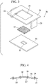
Fig. 3 is an exploded view showing the tissue holding portion of the model for an endoscope. -
Fig. 4 is a cross-sectional view of a tissue holding portion in a modified example. -
Fig. 5 is a diagram showing a second member in a model for an endoscope according to a second embodiment of the present invention. -
Fig. 6 is a perspective view showing a second member in a modified example of a model for an endoscope of the present invention. - A first embodiment of the present invention will be described with reference to
Figs. 1 to 4 .Fig. 1 is a diagram showing a model 1 for an endoscope according to the present embodiment. The model 1 for an endoscope is a model simulating a human stomach. The model 1 for an endoscope includes abasic shape portion 10 formed to simulate a stomach, and atissue holding portion 20 that is detachably attached to thebasic shape portion 10. - The
basic shape portion 10 is formed by appropriately setting its shape and material, depending on tubular organs or tubular parts serving as a target of training and performance evaluation (hereinafter referred to as "training or the like") of an endoscope and a treatment tool for the endoscope. Amounting hole 11 communicating with the interior space is provided at thebasic shape portion 10. Ahard fixing frame 12 to which thetissue holding portion 20 is detachably attached is mounted on the circumferential edge portion of themounting hole 11. The shape of thefixing frame 12 is formed to correspond to the shape of thetissue holding portion 20. -
Fig. 2 is a bottom view of thetissue holding portion 20.Fig. 3 is an exploded view showing thetissue holding portion 20. Thetissue holding portion 20 includes a hardfirst member 21 detachably attached to thefixing frame 12, and asecond member 26 which is formed of a material more flexible than thefirst member 21 and is mounted to thefirst member 21. - The
first member 21 is formed of a material having relatively high rigidity, such as metal or resin. Thefirst member 21 is formed in a frame shape by forming a rectangular throughhole 22 in the central portion.Claw portions 23 for being engaged with the fixing frame are provided on the circumferential edges of thefirst member 21. The presence or absence of theclaw portions 23, the number of theclaw portions 23 that are provided, and the shapes and the positions thereof can be appropriately set. - The
second member 26 is formed of a material more flexible than thefirst member 21, for example, rubber or silicone, in a sheet shape, and can be elastically deformed by applying a force in a surface direction. By forming thesecond member 26 such that arectangular window portion 27 penetrates the central portion of thesecond member 26 in the thickness direction, thesecond member 26 is formed in a frame shape similar to thefirst member 21. As shown inFig. 3 , an area of thewindow portion 27 is smaller than an area of the throughhole 22. It is possible to dispose thefirst member 21 and thesecond member 26 such that they overlap each other so that thewhole window portion 27 is located in the throughhole 22. - A piece of tissue TP is formed in a shape and a size capable of covering the
window portion 27. The piece of tissue TP is disposed to cover thewhole window portion 27 and is fixed to thesecond member 26 by alinear member 28. As thelinear member 28, it is possible to use a medical suture, a sewing thread, a resin gut, or the like. - The
first member 21 and thesecond member 26 are fixed on the outside of the throughhole 22 and thewindow portion 27 by a plurality ofpins 24. Thesecond member 26 is fixed to thefirst member 21 in a state in which thesecond member 26 is stretched in the surface direction and elastically deformed. Thus, tension of magnitude corresponding to the elastic deformation acts on thesecond member 26 and the piece of tissue TP fixed to thesecond member 26. - When forming the
tissue holding portion 20 to which the piece of tissue TP is fixed, first, the piece of tissue TP is fixed to thesecond member 26 by thelinear member 28 to overlap thewindow portion 27. Thereafter, thesecond member 26 is fixed to thefirst member 21 in a state in which tension acts on thesecond member 26. For example, first, parts of the circumferential edge portion of thesecond member 26 are fixed to thefirst member 21 by thepins 24, and the non-fixed parts of the circumferential edge portion are stretched and elastically deformed to be spaced apart from the fixed parts. Thereafter, the remaining parts of the circumferential edge portion are fixed to thefirst member 21, while the elastically deformed state is maintained. - When the piece of tissue TP is attached to the
tissue holding portion 20, theclaw portions 23 of thefirst member 21 are engaged with thefixing frame 12 while causing thesecond member 26 to face thebasic shape portion 10, and thetissue holding portion 20 is attached to thebasic shape portion 10. Thus, the model 1 for an endoscope becomes usable. - A user can perform training or the like in the desired contents by inserting an endoscope (not shown) into the
basic shape portion 10 to move the tip of the endoscope to the vicinity of thewindow portion 27, or by performing procedures on a part of the piece of tissue TP exposed from thewindow portion 27 using a treatment tool (not shown) inserted into the endoscope. When training or the like concerning a procedure is performed, a plurality oftissue holding portions 20 with pieces of tissue fixed thereto are prepared in advance and thetissue holding portions 20 are sequentially replaced after the procedure is performed, and thus training or the like can be continuously performed. When training or the like is performed using an energized treatment tool such as a high-frequency knife, a counter electrode member having conductivity is attached to an end portion of the piece of tissue TP, or the counter electrode member attached to the distant position and the piece of tissue TP are connected to a gauze soaked in saline, and thus the power supply can be applied to the piece of tissue TP. - Tension caused by the elastic force of the
second member 26 acts on the piece of tissue TP exposed through thewindow portion 27. Thus, for example, when training or the like is performed on the piece of tissue TP, it is possible to reproduce conditions similar to those of a procedure actually performed on a living body with regard to the behavior and feeling of the tissue and it is possible to effectively perform training or the like. - As described above, according to the model 1 for an endoscope of the present embodiment, in the
tissue holding portion 20 on which the piece of tissue TP is held, the piece of tissue TP is fixed to thefirst member 21 via thesecond member 26 that is more flexible than the first member, rather than being directly fixed to the hardfirst member 21. Accordingly, even when the size of the piece of tissue TP is reduced for uniformity of the tissue when a plurality of pieces of tissue are prepared, the distance between the tissue exposed from the window portion and the part fixed to thefirst member 21 can be sufficiently secured by thesecond member 26. As a result, it is possible to reduce the influence of thefirst member 21 on the tension acting on the piece of tissue TP, and to approximate the behavior and feeling of the tissue to those of actual tissue. - Further, in general, since the surface of the piece of tissue is very slippery, it is difficult to fix the piece of tissue to the first member in a state in which the tension acts on the piece of tissue. However, when the piece of tissue is fixed via the
second member 26, even if the piece of tissue is fixed to thesecond member 26 in a state in which the tension does not act on the piece of tissue, by fixing the piece of tissue to thefirst member 21 by causing the tension to act on thesecond member 26 thereafter, it is possible to allow the tension to easily act on the piece of tissue TP. Therefore, it is possible to very easily perform the work of fixing the piece of tissue TP to thetissue holding portion 20 in a state in which the tension acts on the piece of tissue TP, and even when a plurality of tissue holding portions are prepared in advance, the tissue holding portions can be efficiently prepared. - Further, when the
second member 26 is attached to thefirst member 21, the edge of the opening of thewindow portion 27 extends to the inner side from the edge of the opening of the throughhole 22 over the entire circumference, and is located on the inner side from the edge of the opening of the throughhole 22 of thefirst member 21. That is, the opening area of thewindow portion 27 is smaller than the opening area of the throughhole 22. In this case, the tissue fixed to thewindow portion 27 can be connected to thefirst member 21 via thesecond member 26 over the entire circumference. As a result, it is possible to approximate the tension acting on the piece of tissue TP to natural tension (tension acting on tissue of an actual patient). - In the present embodiment, although an example in which the piece of tissue is disposed between the first member and the second member in the thickness direction of the tissue holding portion has been described, the arrangement is not limited thereto. For example, as in a modified example shown in
Fig. 4 , thesecond member 26 may be disposed between the piece of tissue TP and thefirst member 21. Further, even when the piece of tissue is disposed between the first member and the second member, as long as the piece of tissue is not directly fixed to the first member, a part of the piece of tissue may be disposed to be interposed between the first member and the second member. - Further, the fixing manner of the piece of tissue and the second member, and the fixing manner of the second member and the first member are not limited to the aforementioned examples, and may be used by appropriately selecting various known fixing means.
- Next, a second embodiment of the present invention will be described with reference to
Fig. 5 . The present embodiment differs from the first embodiment in the structure of the second member. In addition, in the following description, the configurations common to those described above will be denoted by the same reference numerals and a repeated description will not be provided. -
Fig. 5 is a plan view showing asecond member 31 in a tissue holding portion according to a model for an endoscope of the present embodiment. Thesecond member 31 is configured using afirst material 32 that is more flexible than thefirst member 21, and asecond material 33 that is more flexible than thefirst material 32. - Both of the
first material 32 and thesecond material 33 are formed in a sheet shape having a rectangular shape in a plan view. As shown inFig. 5 , two pieces of thefirst material 32 are disposed on both sides in the longitudinal direction of therectangular window portion 27, and two pieces of thesecond material 33 are disposed on both sides in the width direction (lateral direction) of thewindow portion 27. Thefirst material 32 and thesecond material 33 are connected to each other in this arrangement, and thus thesecond member 31 of the present embodiment is formed. Thesecond member 31 is more easily stretched in the longitudinal direction of thewindow portion 27 due to the aforementioned structure, thus providing anisotropic flexibility. - In the model for an endoscope of the present embodiment, similarly to the first embodiment, it is also possible to achieve both uniformity of the tissue and reproduction of the condition similar to that of a procedure actually performed in a living body. Further, since the
second member 31 is configured to have anisotropic flexibility, when the orientation is appropriately set at the time of fixing to the first member in consideration of the aforementioned anisotropy, the behavior and feeling of the tissue can further approximate those of the desired tubular organ. As a result, it is possible to further enhance the quality of training or the like. - Although an example in which the second member is formed using two types of materials with different flexibility has been described in the present embodiment, a method of providing anisotropic flexibility of the second member is not limited thereto. Accordingly, the second member may be formed using three or more kinds of materials with different flexibility, or the second member may be formed using a single material that already has anisotropic flexibility.
- Although the model for an endoscope of the present invention has been described using the embodiments, the technical scope of the present invention is not limited to the aforementioned embodiments, and it is possible to change the combinations of the constituent elements or to add various changes to the constituent elements or delete them without departing from the scope of the present invention.
- For example, in the present invention, the basic shape portion may be flexibly formed. However, in this case, at least the fixing frame is formed of a hard material so that tension can be appropriately provided to the piece of tissue.
- Moreover, the first member may be provided in the basic shape portion without being provided in the tissue holding portion. For example, the
aforementioned fixing frame 12 is provided as the first member, and as in thesecond member 26A of the modified example shown inFig. 6 , the second member is formed to have aplanar portion 29a having awindow portion 27, and afitting portion 29b which rises from the circumferential edges of theplanar portion 29a with respect to theplanar portion 29a at an angle. As long as the piece of tissue is fixed to thesecond member 26A and thefitting portion 29b is fitted at the outside of the fixingframe 12 and attached to the fixingframe 12 in a state in which theplanar portion 29a is stretched, it is possible to allow tension to act on the second member and the piece of tissue fixed to the second member. - Further, the shapes of the through hole and the window portion, and the external shapes in the plan view of the first member and the second member may not be rectangular and may be appropriately set.
- Further, in the model for an endoscope of the present invention, the piece of tissue may not necessarily be attached to the second member to completely cover the window portion, and at least a part of the piece of tissue may be disposed to overlap the window portion.
- In addition, the basic shape portion is not essential in the model for an endoscope of the present invention. Thus, it is also possible to use only the aforementioned
tissue holding portion 20 depending on the content of training or the like. - Further, in the model for an endoscope of the present invention, the basic shape portion is not limited to the model of the human stomach. As long as the basic shape portion is a model (a human body model) that simulates a human digestive tract (large intestine, esophagus, or the like), similar training effects can be obtained.
- The present invention is not limited by the aforementioned description, and is only limited by the scope of the appended claims.
- According to the model for an endoscope of the present invention, it is possible to achieve both uniformity of the tissue and reproduction of the condition similar to that of a procedure actually performed in a living body.
-
- 1:
- model for endoscope
- 21:
- first member
- 22:
- through hole
- 26, 26A, 31:
- second member
- 27:
- window portion
- TP:
- piece of tissue
Claims (3)
- A model for an endoscope comprising
a tissue holding portion including:a first member having a through hole, the first member being hard and formed in a frame shape; anda second member formed in a sheet shape with a material that is more flexible than the first member and is elastically deformable, the second member having a window portion that penetrates the second member in a thickness direction of the second member, the second member being attached to the first member,wherein a piece of tissue is attached to the second member such that the piece of tissue overlaps the window portion, and the second member is attached to the first member in a state in which the second member is elastically deformed so that tension acts on the second member. - The model according to claim 1, wherein the second member is configured to have anisotropic flexibility.
- The model according to claim 1 or 2, wherein the second member is attached to the first member such that the window portion is entirely located at an inner side of the through hole.
Applications Claiming Priority (2)
| Application Number | Priority Date | Filing Date | Title |
|---|---|---|---|
| JP2014137726 | 2014-07-03 | ||
| PCT/JP2015/065766 WO2016002411A1 (en) | 2014-07-03 | 2015-06-01 | Model for endoscope |
Publications (2)
| Publication Number | Publication Date |
|---|---|
| EP3165148A1 true EP3165148A1 (en) | 2017-05-10 |
| EP3165148A4 EP3165148A4 (en) | 2017-12-06 |
Family
ID=55018963
Family Applications (1)
| Application Number | Title | Priority Date | Filing Date |
|---|---|---|---|
| EP15814914.6A Withdrawn EP3165148A4 (en) | 2014-07-03 | 2015-06-01 | Model for endoscope |
Country Status (5)
| Country | Link |
|---|---|
| US (1) | US10043416B2 (en) |
| EP (1) | EP3165148A4 (en) |
| JP (1) | JP5914785B1 (en) |
| CN (1) | CN105848555B (en) |
| WO (1) | WO2016002411A1 (en) |
Families Citing this family (5)
| Publication number | Priority date | Publication date | Assignee | Title |
|---|---|---|---|---|
| KR102448467B1 (en) * | 2016-04-26 | 2022-09-28 | 어플라이드 메디컬 리소시스 코포레이션 | Residual stress features in long-term models |
| JP7272759B2 (en) * | 2018-07-17 | 2023-05-12 | 株式会社ワインレッド | Endoscope operation training device |
| JP7633614B2 (en) * | 2021-01-18 | 2025-02-20 | KOTOBUKI Medical株式会社 | Medical equipment operation training device |
| US20230343243A1 (en) * | 2022-04-22 | 2023-10-26 | Covidien Lp | Regenerative artificial tissue for electrosurgical robotic assisted surgery training and testing |
| KR102865844B1 (en) * | 2022-11-30 | 2025-09-29 | 주식회사 엔도로보틱스 | Apparatus for surgery training |
Family Cites Families (13)
| Publication number | Priority date | Publication date | Assignee | Title |
|---|---|---|---|---|
| US2017250A (en) * | 1933-11-02 | 1935-10-15 | Jones Ira Milton | Leather stretching frame |
| US4386917A (en) * | 1981-09-16 | 1983-06-07 | Forrest Leonard E | Suturing training device and method |
| US5358408A (en) * | 1993-03-09 | 1994-10-25 | Marelyn Medina | Tissue specimen suspension device |
| JP3616031B2 (en) * | 2001-05-10 | 2005-02-02 | 富士通株式会社 | Anisotropic conductive sheet, method for manufacturing the same, electronic device and inspection device for operation test |
| JP2004049479A (en) * | 2002-07-18 | 2004-02-19 | Olympus Corp | Training device for endoscope |
| JP2004347623A (en) | 2003-03-26 | 2004-12-09 | National Institute Of Advanced Industrial & Technology | Human phantom and manufacturing method thereof |
| JP2006116206A (en) * | 2004-10-25 | 2006-05-11 | Koken Co Ltd | Endoscopic dissection model for endoscope |
| US8465771B2 (en) * | 2005-03-30 | 2013-06-18 | The University Of Western Ontario | Anisotropic hydrogels |
| EP1964086A1 (en) * | 2005-12-13 | 2008-09-03 | Erbe Elektromedizin GmbH | Training model for the endoscopic investigation and treatment of hollow organs |
| JP5289714B2 (en) * | 2007-02-14 | 2013-09-11 | 株式会社高研 | ESD training model |
| US8999378B2 (en) * | 2008-09-24 | 2015-04-07 | President And Fellows Of Harvard College | Porous electroactive hydrogels and uses thereof |
| EP4276801A3 (en) * | 2012-09-27 | 2024-01-03 | Applied Medical Resources Corporation | Surgical training model for laparoscopic procedures |
| AU2014293036B2 (en) * | 2013-07-24 | 2017-12-21 | Applied Medical Resources Corporation | First entry model |
-
2015
- 2015-06-01 CN CN201580003448.1A patent/CN105848555B/en active Active
- 2015-06-01 EP EP15814914.6A patent/EP3165148A4/en not_active Withdrawn
- 2015-06-01 JP JP2015560429A patent/JP5914785B1/en active Active
- 2015-06-01 WO PCT/JP2015/065766 patent/WO2016002411A1/en not_active Ceased
-
2016
- 2016-07-06 US US15/202,942 patent/US10043416B2/en active Active
Also Published As
| Publication number | Publication date |
|---|---|
| US10043416B2 (en) | 2018-08-07 |
| JP5914785B1 (en) | 2016-05-11 |
| EP3165148A4 (en) | 2017-12-06 |
| CN105848555A (en) | 2016-08-10 |
| WO2016002411A1 (en) | 2016-01-07 |
| US20160314714A1 (en) | 2016-10-27 |
| JPWO2016002411A1 (en) | 2017-04-27 |
| CN105848555B (en) | 2018-04-13 |
Similar Documents
| Publication | Publication Date | Title |
|---|---|---|
| US10043416B2 (en) | Model for endoscope | |
| US9642642B2 (en) | Guide tip introducer and method to create thereof | |
| JP6916781B2 (en) | Hysterectomy model | |
| JP6206894B2 (en) | Abdominal simulator | |
| KR20200102462A (en) | Anterior rectal mesenteric surgery simulator | |
| JP2010085512A (en) | Endermic technique simulator | |
| JP2019207304A (en) | Laparoscopic surgery training tool | |
| JP6133015B2 (en) | Procedure simulator and simulation method using the same | |
| KR20180033189A (en) | Appendectomy model | |
| JP3197290U (en) | High-frequency female treatment practice model | |
| JP2021525904A (en) | Hilum surgery simulation system | |
| JP2006116206A (en) | Endoscopic dissection model for endoscope | |
| US10068498B2 (en) | Organ model for endoscope | |
| JP2019012126A (en) | Endoscopy training device | |
| US20190172370A1 (en) | Neurosurgical Laparoscopy Training Device and Method of Training | |
| JP3199600U (en) | Surgical practice device | |
| US20140099619A1 (en) | Model for practicing cutting | |
| JP6466886B2 (en) | Surgical fingertip extension | |
| KR200450794Y1 (en) | Endoscope exerciser | |
| KR20200036323A (en) | Body model |
Legal Events
| Date | Code | Title | Description |
|---|---|---|---|
| STAA | Information on the status of an ep patent application or granted ep patent |
Free format text: STATUS: THE INTERNATIONAL PUBLICATION HAS BEEN MADE |
|
| PUAI | Public reference made under article 153(3) epc to a published international application that has entered the european phase |
Free format text: ORIGINAL CODE: 0009012 |
|
| STAA | Information on the status of an ep patent application or granted ep patent |
Free format text: STATUS: REQUEST FOR EXAMINATION WAS MADE |
|
| 17P | Request for examination filed |
Effective date: 20170117 |
|
| AK | Designated contracting states |
Kind code of ref document: A1 Designated state(s): AL AT BE BG CH CY CZ DE DK EE ES FI FR GB GR HR HU IE IS IT LI LT LU LV MC MK MT NL NO PL PT RO RS SE SI SK SM TR |
|
| AX | Request for extension of the european patent |
Extension state: BA ME |
|
| DAV | Request for validation of the european patent (deleted) | ||
| DAX | Request for extension of the european patent (deleted) | ||
| A4 | Supplementary search report drawn up and despatched |
Effective date: 20171106 |
|
| RIC1 | Information provided on ipc code assigned before grant |
Ipc: A61B 1/00 20060101AFI20171027BHEP Ipc: G09B 23/30 20060101ALI20171027BHEP Ipc: G09B 23/28 20060101ALI20171027BHEP |
|
| GRAP | Despatch of communication of intention to grant a patent |
Free format text: ORIGINAL CODE: EPIDOSNIGR1 |
|
| STAA | Information on the status of an ep patent application or granted ep patent |
Free format text: STATUS: GRANT OF PATENT IS INTENDED |
|
| INTG | Intention to grant announced |
Effective date: 20190614 |
|
| STAA | Information on the status of an ep patent application or granted ep patent |
Free format text: STATUS: THE APPLICATION IS DEEMED TO BE WITHDRAWN |
|
| 18D | Application deemed to be withdrawn |
Effective date: 20191025 |