EP3165138A1 - Household electrical appliances with the container - Google Patents
Household electrical appliances with the container Download PDFInfo
- Publication number
- EP3165138A1 EP3165138A1 EP16197087.6A EP16197087A EP3165138A1 EP 3165138 A1 EP3165138 A1 EP 3165138A1 EP 16197087 A EP16197087 A EP 16197087A EP 3165138 A1 EP3165138 A1 EP 3165138A1
- Authority
- EP
- European Patent Office
- Prior art keywords
- spiral spring
- volute spiral
- household appliance
- container
- mounting base
- Prior art date
- Legal status (The legal status is an assumption and is not a legal conclusion. Google has not performed a legal analysis and makes no representation as to the accuracy of the status listed.)
- Granted
Links
Images


Classifications
-
- A—HUMAN NECESSITIES
- A47—FURNITURE; DOMESTIC ARTICLES OR APPLIANCES; COFFEE MILLS; SPICE MILLS; SUCTION CLEANERS IN GENERAL
- A47J—KITCHEN EQUIPMENT; COFFEE MILLS; SPICE MILLS; APPARATUS FOR MAKING BEVERAGES
- A47J37/00—Baking; Roasting; Grilling; Frying
- A47J37/06—Roasters; Grills; Sandwich grills
- A47J37/0611—Roasters; Grills; Sandwich grills the food being cooked between two heating plates, e.g. waffle-irons
-
- A—HUMAN NECESSITIES
- A47—FURNITURE; DOMESTIC ARTICLES OR APPLIANCES; COFFEE MILLS; SPICE MILLS; SUCTION CLEANERS IN GENERAL
- A47J—KITCHEN EQUIPMENT; COFFEE MILLS; SPICE MILLS; APPARATUS FOR MAKING BEVERAGES
- A47J37/00—Baking; Roasting; Grilling; Frying
- A47J37/06—Roasters; Grills; Sandwich grills
- A47J37/0611—Roasters; Grills; Sandwich grills the food being cooked between two heating plates, e.g. waffle-irons
- A47J2037/0617—Roasters; Grills; Sandwich grills the food being cooked between two heating plates, e.g. waffle-irons with means to adjust the distance between heating plates
Definitions
- the present utility model relates to a household appliance having a container, and in particular, to a cover body structure of a household appliance, which is mainly applied to a rice cooker, a capsule coffee maker, a fruit juice maker, or the like.
- An existing household appliance such as a rice cooker or an electric pressure cooker generally includes a machine body and a cover body.
- One end of the cover body and the machine body are hinged by a rotating shaft, the rotating shaft passes through several torsion springs, and the other end of the cover body is provided with a cover-opening mechanism.
- a button of the cover-opening mechanism is pressed and the cover body is bounced off under the action of the torsion springs.
- a bounce-off speed of the cover body in such a structure is fully dependent on elastic force of the torsion springs.
- the elastic force of the torsion springs may be excessively large due to factors such as the material of the torsion springs, and the bounce-off speed of the cover body may be excessively rapid when a user opens the cover body, which causes unbalancing of the machine body, resulting in spilling of food from a container, hurt of an individual, and low safety and reliability.
- a buffering device is used in a household appliance in the market to achieve the purpose of deceleration.
- the purpose of buffering or decelerating a cooker cover can be achieved to a certain extent, relatively large friction force may be apt to cause wearing of a contact surface, resulting in a buffering failure.
- the design is complicated and extra costs are added.
- the present utility model provides a household appliance having a container, so as to resolve at least the prior-art problem of unbalancing of a machine body caused by a rapid bounce speed during opening of a cover body of a household appliance having a container, and wearing of parts thereof during use.
- an aspect of the present utility model provides a household appliance having a container.
- the household appliance is a machine having a container and a cover body, such as a rice cooker, an electric pressure cooker, or a capsule coffee maker.
- the household appliance having a container according to the present utility model has a cover body that closes the container; a mounting base disposed on the container, where the mounting base is provided thereon with a shaft; and a pivot arm disposed on the cover body, where the pivot arm is in rotational connection with the mounting base through the shaft, and further includes: a volute spiral spring connected to the mounting base and the pivot arm separately.
- the volute spiral spring is used to replace a reset spring or a torsion spring used at present, and is mounted on the pivot arm and the mounting base separately.
- the buffering effect is achieved by using the characteristic that the volute spiral spring tightens as the shaft rotates. That is, the volute spiral spring has relatively large recovering force during tightening, but the recovering force reduces accordingly during releasing. Therefore, no vibration is caused, and no extra buffering apparatus needs to be added.
- the mounting base is provided thereon with a projecting portion, and a first end of the volute spiral spring is mounted on the projecting portion; and the pivot arm is provided thereon with a pivot sleeve sleeved on the shaft, and a second end of the volute spiral spring is mounted on the pivot sleeve.
- the first end of the volute spiral spring is a ring-like structure, and is sleeved on the projecting portion.
- the volute spiral spring can be directly sleeved on the projecting portion manually, which is convenient to operate and does not require use of a tool.
- the projecting portion is provided thereon with a fixed part for fixing the first end.
- the fixed part is disposed on the projecting portion to fix the volute spiral spring onto the projecting portion, so as to prevent same from sliding off the projecting portion.
- the fixed part is an elastic buckle.
- the first end of the volute spiral spring is sleeved on the projecting portion by pressing the buckle, and the volute spiral spring is fixed onto the projecting portion after the buckle is released.
- the elastic buckle and the projecting portion are integrally injection-molded.
- integrally injection-molding use and mounting of extra parts are avoided.
- the second end of the volute spiral spring is a ring-like structure, and is sleeved on the pivot sleeve.
- the volute spiral spring can be directly sleeved on the pivot arm manually, which is convenient to operate and does not require use of a tool.
- the second end of the volute spiral spring is a hook-like structure, and is fixedly connected to a clamping block disposed on the pivot arm.
- the other end of the volute spiral spring is configured as a hook-like structure, a corresponding clamping block is disposed on the pivot arm, and the hook-like portion is fixed on the clamping block, so as to fix the volute spiral spring.
- the operation likewise can be directly performed manually, and is simple and convenient and does not require use of a tool.
- the clamping block and the pivot sleeve are provided with a limit slot therebetween, where the second end of the volute spiral spring passes through the limit slot and is fixed onto the clamping block.
- a mounting position of the hook-like portion is further limited by the limit slot, so as to prevent the hook-like portion from offsetting from an operating position thereof.
- the volute spiral spring is detachably mounted on the mounting base and the pivot arm.
- the present utility model resolves the prior-art problems of unbalancing of a machine body caused by a rapid bounce speed during opening of a cover body of a household appliance having a container, and wearing of parts thereof during use.
- the cover body can be opened stably, and therefore the machine body does not vibrate.
- the design has a simple structure and reduces use of parts such as a buffering apparatus.
- a household appliance having a container provided in the present utility model may be a machine having a container and a cover body, such as a rice cooker, an electric pressure cooker, or a capsule coffee maker.
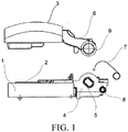
- FIG. 1 is a schematic structural diagram (1) of the household appliance in the first embodiment
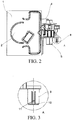
- FIG. 2 is a schematic structural diagram (2) of the household appliance in the first embodiment. As shown in FIG. 1 and FIG. 2 :
- the volute spiral spring 7 is used to replace a reset spring or a torsion spring used at present, and is detachably mounted on the pivot arm 6 and the mounting base 4 separately.
- the buffering effect is achieved by using the characteristic that the volute spiral spring 7 tightens as the shaft 5 rotates. That is, the volute spiral spring 7 has relatively large recovering force when the cover body is closed, but the recovering force reduces accordingly during opening of the cover body, so that no vibration is caused due to excessively large recovering force.
- the features all can be determined according to material coefficients of the volute spiral spring 7. No extra buffering apparatus needs to be added when the volute spiral spring 7 is used.
- the mounting base 4 is provided thereon with a projecting portion 8, and a first end 71 of the volute spiral spring is mounted on the projecting portion 8; and the pivot arm 6 is provided thereon with a pivot sleeve 9 sleeved on the shaft 5, and a second end 72 of the volute spiral spring is mounted on the pivot sleeve 9.
- the first end 71 of the volute spiral spring is a ring-like structure, and is sleeved on the projecting portion 8.
- the volute spiral spring can be directly sleeved on the projecting portion 8 manually, which is convenient to operate and does not require use of a tool.
- FIG. 3 is a schematic enlarged diagram of an area A in FIG. 2 .
- the projecting portion 8 is provided thereon with a fixed part 10 for fixing the first end 71.
- the fixed part is disposed on the projecting portion to fix the volute spiral spring onto the projecting portion, so as to prevent same from sliding off the projecting portion.
- the fixed part 10 is an elastic buckle 11.
- the first end 71 of the volute spiral spring is sleeved on the projecting portion 8 by pressing the elastic buckle 11, and the first end 71 of the volute spiral spring 7 is fixed onto the projecting portion 8 after the elastic buckle 11 is released.
- the elastic buckle 11 and the projecting portion 8 are integrally injection-molded.
- integrally injection-molding of components use and mounting of extra parts (such as a buffering apparatus) are avoided, which is more convenient and cost effective.
- FIG. 4 is a schematic structural diagram of the volute spiral spring in the first embodiment
- FIG. 5 is a schematic installation diagram of the volute spiral spring in the first embodiment
- FIG. 6 is a schematic structural diagram of the cover body in the first embodiment. As shown in FIG. 4, FIG. 5 , and FIG. 6 :
- the second end 72 of the volute spiral spring is a hook-like structure, and is fixedly connected to a clamping block 12 disposed on the pivot arm 6.
- a clamping block 12 By disposing a corresponding clamping block 12 on the pivot arm 9, a hook-like portion of the second end 72 of the volute spiral spring is fixed onto the clamping block 12, so as to fix the volute spiral spring 7.
- the operation likewise can be directly performed manually, and is simple and convenient and does not require use of a tool.
- the clamping block 12 and the pivot sleeve 9 are provided with a limit slot 13 therebetween.
- the second end 72 of the volute spiral spring passes through the limit slot 13 and is fixed onto the clamping block 12.
- a mounting position of the hook-like portion is further limited by the limit slot 13, so as to prevent the hook-like portion from offsetting from an operating position thereof.
- FIG. 7 is a schematic structural diagram of a volute spiral spring in the second embodiment
- FIG. 8 is a schematic installation diagram of the volute spiral spring in the second embodiment. As shown in FIG. 7 and FIG. 8 :
- the first end 71 of the volute spiral spring is a ring-like structure, and is sleeved on the projecting portion 8.
- the projecting portion 8 is provided thereon with a fixed part 10 (that is, the elastic buckle 11) for fixing the first end 71.
- the first end 71 of the volute spiral spring is sleeved on the projecting portion 8 by pressing the elastic buckle 11, and the first end 71 of the volute spiral spring 7 is fixed onto the projecting portion 8 after the elastic buckle 11 is released.
- the second end 72 of the volute spiral spring is a ring-like structure, and is sleeved on the pivot sleeve 9.
- the volute spiral spring can be manually sleeved on the pivot sleeve 9, which is convenient to operate and does not require use of a tool.
- the present utility model resolves the prior-art problems of unbalancing of a machine body caused by a rapid bounce speed during opening, of a cover body of a household appliance having a container, and wearing of parts thereof during use in the prior art.
- the cover body can be opened stably, and therefore the machine body does not vibrate.
- the design has a simple structure and reduces use of parts such as a buffering apparatus.
Landscapes
- Engineering & Computer Science (AREA)
- Food Science & Technology (AREA)
- Cookers (AREA)
Abstract
Description
- The present utility model relates to a household appliance having a container, and in particular, to a cover body structure of a household appliance, which is mainly applied to a rice cooker, a capsule coffee maker, a fruit juice maker, or the like.
- An existing household appliance such as a rice cooker or an electric pressure cooker generally includes a machine body and a cover body. One end of the cover body and the machine body are hinged by a rotating shaft, the rotating shaft passes through several torsion springs, and the other end of the cover body is provided with a cover-opening mechanism. During use, a button of the cover-opening mechanism is pressed and the cover body is bounced off under the action of the torsion springs. However, a bounce-off speed of the cover body in such a structure is fully dependent on elastic force of the torsion springs. The elastic force of the torsion springs may be excessively large due to factors such as the material of the torsion springs, and the bounce-off speed of the cover body may be excessively rapid when a user opens the cover body, which causes unbalancing of the machine body, resulting in spilling of food from a container, hurt of an individual, and low safety and reliability.
- At present, a buffering device is used in a household appliance in the market to achieve the purpose of deceleration. Although the purpose of buffering or decelerating a cooker cover can be achieved to a certain extent, relatively large friction force may be apt to cause wearing of a contact surface, resulting in a buffering failure. Moreover, the design is complicated and extra costs are added.
- At present, no effective solution has been provided with respect to the prior-art problems of unbalancing of a machine body caused by a rapid bounce speed during opening of a cover body of a household appliance having a container, and wearing of parts thereof during use.
- The present utility model provides a household appliance having a container, so as to resolve at least the prior-art problem of unbalancing of a machine body caused by a rapid bounce speed during opening of a cover body of a household appliance having a container, and wearing of parts thereof during use.
- To achieve the objective, an aspect of the present utility model provides a household appliance having a container. The household appliance is a machine having a container and a cover body, such as a rice cooker, an electric pressure cooker, or a capsule coffee maker.
- The household appliance having a container according to the present utility model has a cover body that closes the container; a mounting base disposed on the container, where the mounting base is provided thereon with a shaft; and a pivot arm disposed on the cover body, where the pivot arm is in rotational connection with the mounting base through the shaft, and further includes: a volute spiral spring connected to the mounting base and the pivot arm separately. The volute spiral spring is used to replace a reset spring or a torsion spring used at present, and is mounted on the pivot arm and the mounting base separately. The buffering effect is achieved by using the characteristic that the volute spiral spring tightens as the shaft rotates. That is, the volute spiral spring has relatively large recovering force during tightening, but the recovering force reduces accordingly during releasing. Therefore, no vibration is caused, and no extra buffering apparatus needs to be added.
- Preferably, the mounting base is provided thereon with a projecting portion, and a first end of the volute spiral spring is mounted on the projecting portion; and the pivot arm is provided thereon with a pivot sleeve sleeved on the shaft, and a second end of the volute spiral spring is mounted on the pivot sleeve.
- Preferably, the first end of the volute spiral spring is a ring-like structure, and is sleeved on the projecting portion. By configuring one end of the volute spiral spring as a ring-like structure, the volute spiral spring can be directly sleeved on the projecting portion manually, which is convenient to operate and does not require use of a tool.
- Preferably, the projecting portion is provided thereon with a fixed part for fixing the first end. The fixed part is disposed on the projecting portion to fix the volute spiral spring onto the projecting portion, so as to prevent same from sliding off the projecting portion.
- Preferably, the fixed part is an elastic buckle. The first end of the volute spiral spring is sleeved on the projecting portion by pressing the buckle, and the volute spiral spring is fixed onto the projecting portion after the buckle is released.
- Preferably, the elastic buckle and the projecting portion are integrally injection-molded. By integrally injection-molding, use and mounting of extra parts are avoided.
- In a preferable solution, the second end of the volute spiral spring is a ring-like structure, and is sleeved on the pivot sleeve. By configuring the other end of the volute spiral spring also as a ring-like structure, the volute spiral spring can be directly sleeved on the pivot arm manually, which is convenient to operate and does not require use of a tool.
- In another preferable solution, the second end of the volute spiral spring is a hook-like structure, and is fixedly connected to a clamping block disposed on the pivot arm. The other end of the volute spiral spring is configured as a hook-like structure, a corresponding clamping block is disposed on the pivot arm, and the hook-like portion is fixed on the clamping block, so as to fix the volute spiral spring. The operation likewise can be directly performed manually, and is simple and convenient and does not require use of a tool.
- Preferably, the clamping block and the pivot sleeve are provided with a limit slot therebetween, where the second end of the volute spiral spring passes through the limit slot and is fixed onto the clamping block. A mounting position of the hook-like portion is further limited by the limit slot, so as to prevent the hook-like portion from offsetting from an operating position thereof.
- Preferably, the volute spiral spring is detachably mounted on the mounting base and the pivot arm.
- The present utility model resolves the prior-art problems of unbalancing of a machine body caused by a rapid bounce speed during opening of a cover body of a household appliance having a container, and wearing of parts thereof during use. On the one hand, the cover body can be opened stably, and therefore the machine body does not vibrate. On the other hand, the design has a simple structure and reduces use of parts such as a buffering apparatus.
- The described accompanying drawings described herein are used to provide further understanding of the present utility model and constitute a part of the present application. Exemplary embodiments of the present utility model and description thereof are used to illustrate the present utility model and do not constitute an improper limit to the present utility model.
- FIG. 1
- is a schematic structural diagram (1) of a household appliance in a first embodiment;
- FIG. 2
- is a schematic structural diagram (2) of the household appliance in the first embodiment;
- FIG. 3
- is a schematic enlarged diagram of an area A in
FIG. 2 ; - FIG. 4
- is a schematic structural diagram of a volute spiral spring in the first embodiment;
- FIG. 5
- is a schematic installation diagram of the volute spiral spring in the first embodiment;
- FIG. 6
- is a schematic structural diagram of a cover body in the first embodiment;
- FIG. 7
- is a schematic structural diagram of a volute spiral spring in a second embodiment; and
- FIG. 8
- is a schematic installation diagram of the volute spiral spring in the second embodiment.
- The following describes the present utility model in detail with reference to the accompanying drawings and the embodiments. It should be noted that the embodiments and the features in the embodiments in the present application can be combined with each other providing that no conflict occurs.
- A household appliance having a container provided in the present utility model may be a machine having a container and a cover body, such as a rice cooker, an electric pressure cooker, or a capsule coffee maker.
- In a first embodiment,
FIG. 1 is a schematic structural diagram (1) of the household appliance in the first embodiment, andFIG. 2 is a schematic structural diagram (2) of the household appliance in the first embodiment. As shown inFIG. 1 andFIG. 2 : - The
household appliance 1 has acontainer 2; acover body 3 that closes thecontainer 2; a mountingbase 4 disposed on thecontainer 2, where the mounting base is provided thereon with ashaft 5; and apivot arm 6 disposed on thecover body 3. Thepivot arm 6 is in rotational connection with the mountingbase 4 through theshaft 5. Thehousehold appliance 1 further includes: avolute spiral spring 7 connected to the mountingbase 4 and thepivot arm 6 separately. - The
volute spiral spring 7 is used to replace a reset spring or a torsion spring used at present, and is detachably mounted on thepivot arm 6 and the mountingbase 4 separately. The buffering effect is achieved by using the characteristic that thevolute spiral spring 7 tightens as theshaft 5 rotates. That is, thevolute spiral spring 7 has relatively large recovering force when the cover body is closed, but the recovering force reduces accordingly during opening of the cover body, so that no vibration is caused due to excessively large recovering force. The features all can be determined according to material coefficients of thevolute spiral spring 7. No extra buffering apparatus needs to be added when thevolute spiral spring 7 is used. - Specifically, as shown in
FIG. 2 , the mountingbase 4 is provided thereon with a projectingportion 8, and afirst end 71 of the volute spiral spring is mounted on the projectingportion 8; and thepivot arm 6 is provided thereon with apivot sleeve 9 sleeved on theshaft 5, and asecond end 72 of the volute spiral spring is mounted on thepivot sleeve 9. - Preferably, the
first end 71 of the volute spiral spring is a ring-like structure, and is sleeved on the projectingportion 8. By the ring-like structure, the volute spiral spring can be directly sleeved on the projectingportion 8 manually, which is convenient to operate and does not require use of a tool. - Preferably,
FIG. 3 is a schematic enlarged diagram of an area A inFIG. 2 . As shown inFIG. 3 , the projectingportion 8 is provided thereon with afixed part 10 for fixing thefirst end 71. The fixed part is disposed on the projecting portion to fix the volute spiral spring onto the projecting portion, so as to prevent same from sliding off the projecting portion. - Preferably, as shown in
FIG. 3 , the fixedpart 10 is an elastic buckle 11. Thefirst end 71 of the volute spiral spring is sleeved on the projectingportion 8 by pressing the elastic buckle 11, and thefirst end 71 of thevolute spiral spring 7 is fixed onto the projectingportion 8 after the elastic buckle 11 is released. - Preferably, the elastic buckle 11 and the projecting
portion 8 are integrally injection-molded. By integrally injection-molding of components, use and mounting of extra parts (such as a buffering apparatus) are avoided, which is more convenient and cost effective. -
FIG. 4 is a schematic structural diagram of the volute spiral spring in the first embodiment,FIG. 5 is a schematic installation diagram of the volute spiral spring in the first embodiment, andFIG. 6 is a schematic structural diagram of the cover body in the first embodiment. As shown inFIG. 4, FIG. 5 , andFIG. 6 : - In this embodiment, the
second end 72 of the volute spiral spring is a hook-like structure, and is fixedly connected to aclamping block 12 disposed on thepivot arm 6. By disposing acorresponding clamping block 12 on thepivot arm 9, a hook-like portion of thesecond end 72 of the volute spiral spring is fixed onto the clampingblock 12, so as to fix thevolute spiral spring 7. The operation likewise can be directly performed manually, and is simple and convenient and does not require use of a tool. - Preferably, as shown in
FIG. 6 , the clampingblock 12 and thepivot sleeve 9 are provided with alimit slot 13 therebetween. Thesecond end 72 of the volute spiral spring passes through thelimit slot 13 and is fixed onto the clampingblock 12. A mounting position of the hook-like portion is further limited by thelimit slot 13, so as to prevent the hook-like portion from offsetting from an operating position thereof. - In a second embodiment, some technical features of the first embodiment are used.
FIG. 7 is a schematic structural diagram of a volute spiral spring in the second embodiment, andFIG. 8 is a schematic installation diagram of the volute spiral spring in the second embodiment. As shown inFIG. 7 and FIG. 8 : - The
first end 71 of the volute spiral spring is a ring-like structure, and is sleeved on the projectingportion 8. The projectingportion 8 is provided thereon with a fixed part 10 (that is, the elastic buckle 11) for fixing thefirst end 71. Thefirst end 71 of the volute spiral spring is sleeved on the projectingportion 8 by pressing the elastic buckle 11, and thefirst end 71 of thevolute spiral spring 7 is fixed onto the projectingportion 8 after the elastic buckle 11 is released. - The
second end 72 of the volute spiral spring is a ring-like structure, and is sleeved on thepivot sleeve 9. By configuring theother end 72 of the volute spiral spring also as a ring-like structure, the volute spiral spring can be manually sleeved on thepivot sleeve 9, which is convenient to operate and does not require use of a tool. - The present utility model resolves the prior-art problems of unbalancing of a machine body caused by a rapid bounce speed during opening, of a cover body of a household appliance having a container, and wearing of parts thereof during use in the prior art. On the one hand, the cover body can be opened stably, and therefore the machine body does not vibrate. On the other hand, the design has a simple structure and reduces use of parts such as a buffering apparatus.
- Various specific implementation manners described in the foregoing and shown in the accompanying drawings are only used to illustrate the present utility model, and are not entirety of the present utility model. Within the scope of the basic technical thought of the present utility model, any types of modifications for the present utility model made by persons ordinarily skilled in the art fall within the scope of the present utility model.
Claims (10)
- A household appliance (1) having a container (2), having a cover body (3) that closes the container (2); a mounting base (4) disposed on the container, wherein the mounting base (4) is provided thereon with a shaft (5); and a pivot arm (6) disposed on the cover body (3), wherein the pivot arm (6) is in rotational connection with the mounting base (4) through the shaft (5), characterized by comprising:a volute spiral spring (7) connected to the mounting base (4) and the pivot arm (6) separately.
- The household appliance according to claim 1, characterized in that:the mounting base (4) is provided thereon with a projecting portion (8), and a first end (71) of the volute spiral spring (7) is mounted on the projecting portion; andthe pivot arm (6) is provided thereon with a pivot sleeve (9) sleeved on the shaft (5), and a second end (72) of the volute spiral spring (7) is mounted on the pivot sleeve.
- The household appliance according to claim 2, characterized in that:the first end (71) of the volute spiral spring (7) is a ring-like structure, and is sleeved on the projecting portion (8).
- The household appliance according to claim 3, characterized in that:the projecting portion (8) is provided thereon with a fixed part (10) for fixing the first end (71).
- The household appliance according to claim 4, characterized in that:the fixed part (10) is an elastic buckle (11).
- The household appliance according to claim 5, characterized in that:the elastic buckle (11) and the projecting portion (8) are integrally injection-molded.
- The household appliance according to claim 3, characterized in that:the second end (72) of the volute spiral spring (7) is a ring-like structure, and is sleeved on the pivot sleeve (9).
- The household appliance according to claim 3, characterized in that:the second end (72) of the volute spiral spring (7) is a hook-like structure, and is fixedly connected to a clamping block (12) disposed on the pivot arm (9).
- The household appliance according to claim 8, characterized in that:the clamping block (12) and the pivot sleeve (9) are provided with a limit slot (13) therebetween,wherein the second end (72) of the volute spiral spring (7) passes through the limit slot (13) and is fixed onto the clamping block (12).
- The household appliance according to claim 1, characterized in that:the volute spiral spring (7) is detachably mounted on the mounting base (4) and the pivot arm (6).
Applications Claiming Priority (1)
| Application Number | Priority Date | Filing Date | Title |
|---|---|---|---|
| CN201520874111.5U CN205214946U (en) | 2015-11-04 | 2015-11-04 | Domestic appliance with container |
Publications (2)
| Publication Number | Publication Date |
|---|---|
| EP3165138A1 true EP3165138A1 (en) | 2017-05-10 |
| EP3165138B1 EP3165138B1 (en) | 2019-09-04 |
Family
ID=55890051
Family Applications (1)
| Application Number | Title | Priority Date | Filing Date |
|---|---|---|---|
| EP16197087.6A Active EP3165138B1 (en) | 2015-11-04 | 2016-11-03 | Household electrical appliances with the container |
Country Status (2)
| Country | Link |
|---|---|
| EP (1) | EP3165138B1 (en) |
| CN (1) | CN205214946U (en) |
Cited By (3)
| Publication number | Priority date | Publication date | Assignee | Title |
|---|---|---|---|---|
| CN110089961A (en) * | 2018-08-30 | 2019-08-06 | 江门市西屋厨房小家电有限公司 | A kind of mounting structure of cooking machine pot body |
| CN110301832A (en) * | 2019-06-25 | 2019-10-08 | 宁波市悦达电子科技有限公司 | One kind is uncapped convenient food processor |
| FR3094193A1 (en) * | 2019-03-29 | 2020-10-02 | Roller Grill International | Grill-type device for cooking / toasting food equipped with braking means |
Families Citing this family (1)
| Publication number | Priority date | Publication date | Assignee | Title |
|---|---|---|---|---|
| CN107374337B (en) * | 2017-08-16 | 2023-07-28 | 珠海格力电器股份有限公司 | Uncapping device and cooker |
Citations (5)
| Publication number | Priority date | Publication date | Assignee | Title |
|---|---|---|---|---|
| EP1400195A1 (en) * | 2002-09-20 | 2004-03-24 | Seb S.A. | Domestic appliance consisting of hinged sections |
| FR2866539A1 (en) * | 2004-02-23 | 2005-08-26 | Seb Sa | Electric household appliance e.g. waffle iron, has toothed wheel that is coupled to shock absorber during opening of upper and lower panels in such manner to reduce opening speed of upper and lower panels |
| DE202009017688U1 (en) * | 2009-12-29 | 2010-06-02 | Tsann Kuen (Zhangzhou) Enterprise Co., Ltd., Zhangzhou | A grill open in two directions |
| CN203953386U (en) * | 2014-07-18 | 2014-11-26 | 漳州灿坤实业有限公司 | A kind of baking tray spacing is adjustable decocts roasting device |
| CN204146880U (en) * | 2014-11-11 | 2015-02-11 | 佛山市顺德区美的电热电器制造有限公司 | Automatic uncovering structure and there is the electric cooking appliance of this automatic uncovering structure |
-
2015
- 2015-11-04 CN CN201520874111.5U patent/CN205214946U/en not_active Expired - Lifetime
-
2016
- 2016-11-03 EP EP16197087.6A patent/EP3165138B1/en active Active
Patent Citations (5)
| Publication number | Priority date | Publication date | Assignee | Title |
|---|---|---|---|---|
| EP1400195A1 (en) * | 2002-09-20 | 2004-03-24 | Seb S.A. | Domestic appliance consisting of hinged sections |
| FR2866539A1 (en) * | 2004-02-23 | 2005-08-26 | Seb Sa | Electric household appliance e.g. waffle iron, has toothed wheel that is coupled to shock absorber during opening of upper and lower panels in such manner to reduce opening speed of upper and lower panels |
| DE202009017688U1 (en) * | 2009-12-29 | 2010-06-02 | Tsann Kuen (Zhangzhou) Enterprise Co., Ltd., Zhangzhou | A grill open in two directions |
| CN203953386U (en) * | 2014-07-18 | 2014-11-26 | 漳州灿坤实业有限公司 | A kind of baking tray spacing is adjustable decocts roasting device |
| CN204146880U (en) * | 2014-11-11 | 2015-02-11 | 佛山市顺德区美的电热电器制造有限公司 | Automatic uncovering structure and there is the electric cooking appliance of this automatic uncovering structure |
Cited By (4)
| Publication number | Priority date | Publication date | Assignee | Title |
|---|---|---|---|---|
| CN110089961A (en) * | 2018-08-30 | 2019-08-06 | 江门市西屋厨房小家电有限公司 | A kind of mounting structure of cooking machine pot body |
| CN110089961B (en) * | 2018-08-30 | 2024-02-06 | 江门市西屋厨房小家电有限公司 | Mounting structure of cooking machine pot body |
| FR3094193A1 (en) * | 2019-03-29 | 2020-10-02 | Roller Grill International | Grill-type device for cooking / toasting food equipped with braking means |
| CN110301832A (en) * | 2019-06-25 | 2019-10-08 | 宁波市悦达电子科技有限公司 | One kind is uncapped convenient food processor |
Also Published As
| Publication number | Publication date |
|---|---|
| EP3165138B1 (en) | 2019-09-04 |
| CN205214946U (en) | 2016-05-11 |
Similar Documents
| Publication | Publication Date | Title |
|---|---|---|
| US6776086B1 (en) | Safety switch for a food processor | |
| EP3165138B1 (en) | Household electrical appliances with the container | |
| CA2581494A1 (en) | Juice extractor | |
| CN109091033A (en) | Stirring cup assembly for food processor and food processor comprising same | |
| US10702093B2 (en) | Brewing apparatus | |
| CN105569475B (en) | A kind of high-performance household electrical appliance door lock and household electrical appliance | |
| CN110025234B (en) | a food processing device | |
| CN204033078U (en) | Pressure cooker | |
| CN109084522A (en) | Push type adjustable knob structure and the adjustable refrigerator drawer of dry and wet | |
| CN106943041B (en) | Household cooking appliance comprising a drive device for a rotary tool equipped with a braking system | |
| CN108354477A (en) | A kind of shredding machine safe to use | |
| CN210144536U (en) | a food processing device | |
| KR200459407Y1 (en) | electric cooker with auxiliary opening device | |
| CN210930918U (en) | Cooking device | |
| CN212912811U (en) | Lid assembly and have its cooking utensil | |
| CN112020317B (en) | Beverage preparation machine for brewing beverages with a cover plate for covering an opening formed in a housing wall | |
| CN208926019U (en) | Frame subassembly and cooking machine | |
| CN204410584U (en) | Electric cooker and cooker cover hand-clamping prevention device thereof | |
| CN217408584U (en) | Be applied to conversion cup, cooking device and cooking machine of cooking machine | |
| CN201030318Y (en) | food processor | |
| CN106955035B (en) | Rotary Cooking Device | |
| CN205812111U (en) | There is mobile phone shell and the mobile phone of card lid ejecting structure | |
| CN209203011U (en) | Frame subassembly and cooking machine | |
| JP3112631B2 (en) | Cooking device | |
| CN216932840U (en) | Safety switch triggering structure, food processor and juicer |
Legal Events
| Date | Code | Title | Description |
|---|---|---|---|
| PUAI | Public reference made under article 153(3) epc to a published international application that has entered the european phase |
Free format text: ORIGINAL CODE: 0009012 |
|
| STAA | Information on the status of an ep patent application or granted ep patent |
Free format text: STATUS: THE APPLICATION HAS BEEN PUBLISHED |
|
| AK | Designated contracting states |
Kind code of ref document: A1 Designated state(s): AL AT BE BG CH CY CZ DE DK EE ES FI FR GB GR HR HU IE IS IT LI LT LU LV MC MK MT NL NO PL PT RO RS SE SI SK SM TR |
|
| AX | Request for extension of the european patent |
Extension state: BA ME |
|
| RIN1 | Information on inventor provided before grant (corrected) |
Inventor name: WU, LIANSEN Inventor name: LI, ZHENGHAI Inventor name: LU, PENG |
|
| STAA | Information on the status of an ep patent application or granted ep patent |
Free format text: STATUS: REQUEST FOR EXAMINATION WAS MADE |
|
| 17P | Request for examination filed |
Effective date: 20171110 |
|
| RBV | Designated contracting states (corrected) |
Designated state(s): AL AT BE BG CH CY CZ DE DK EE ES FI FR GB GR HR HU IE IS IT LI LT LU LV MC MK MT NL NO PL PT RO RS SE SI SK SM TR |
|
| GRAP | Despatch of communication of intention to grant a patent |
Free format text: ORIGINAL CODE: EPIDOSNIGR1 |
|
| STAA | Information on the status of an ep patent application or granted ep patent |
Free format text: STATUS: GRANT OF PATENT IS INTENDED |
|
| INTG | Intention to grant announced |
Effective date: 20190430 |
|
| GRAS | Grant fee paid |
Free format text: ORIGINAL CODE: EPIDOSNIGR3 |
|
| GRAA | (expected) grant |
Free format text: ORIGINAL CODE: 0009210 |
|
| STAA | Information on the status of an ep patent application or granted ep patent |
Free format text: STATUS: THE PATENT HAS BEEN GRANTED |
|
| AK | Designated contracting states |
Kind code of ref document: B1 Designated state(s): AL AT BE BG CH CY CZ DE DK EE ES FI FR GB GR HR HU IE IS IT LI LT LU LV MC MK MT NL NO PL PT RO RS SE SI SK SM TR |
|
| REG | Reference to a national code |
Ref country code: GB Ref legal event code: FG4D |
|
| REG | Reference to a national code |
Ref country code: CH Ref legal event code: EP |
|
| REG | Reference to a national code |
Ref country code: AT Ref legal event code: REF Ref document number: 1174167 Country of ref document: AT Kind code of ref document: T Effective date: 20190915 |
|
| REG | Reference to a national code |
Ref country code: DE Ref legal event code: R096 Ref document number: 602016019805 Country of ref document: DE |
|
| REG | Reference to a national code |
Ref country code: IE Ref legal event code: FG4D |
|
| REG | Reference to a national code |
Ref country code: NL Ref legal event code: MP Effective date: 20190904 |
|
| REG | Reference to a national code |
Ref country code: LT Ref legal event code: MG4D |
|
| PG25 | Lapsed in a contracting state [announced via postgrant information from national office to epo] |
Ref country code: HR Free format text: LAPSE BECAUSE OF FAILURE TO SUBMIT A TRANSLATION OF THE DESCRIPTION OR TO PAY THE FEE WITHIN THE PRESCRIBED TIME-LIMIT Effective date: 20190904 Ref country code: LT Free format text: LAPSE BECAUSE OF FAILURE TO SUBMIT A TRANSLATION OF THE DESCRIPTION OR TO PAY THE FEE WITHIN THE PRESCRIBED TIME-LIMIT Effective date: 20190904 Ref country code: BG Free format text: LAPSE BECAUSE OF FAILURE TO SUBMIT A TRANSLATION OF THE DESCRIPTION OR TO PAY THE FEE WITHIN THE PRESCRIBED TIME-LIMIT Effective date: 20191204 Ref country code: NO Free format text: LAPSE BECAUSE OF FAILURE TO SUBMIT A TRANSLATION OF THE DESCRIPTION OR TO PAY THE FEE WITHIN THE PRESCRIBED TIME-LIMIT Effective date: 20191204 Ref country code: SE Free format text: LAPSE BECAUSE OF FAILURE TO SUBMIT A TRANSLATION OF THE DESCRIPTION OR TO PAY THE FEE WITHIN THE PRESCRIBED TIME-LIMIT Effective date: 20190904 Ref country code: FI Free format text: LAPSE BECAUSE OF FAILURE TO SUBMIT A TRANSLATION OF THE DESCRIPTION OR TO PAY THE FEE WITHIN THE PRESCRIBED TIME-LIMIT Effective date: 20190904 |
|
| PG25 | Lapsed in a contracting state [announced via postgrant information from national office to epo] |
Ref country code: RS Free format text: LAPSE BECAUSE OF FAILURE TO SUBMIT A TRANSLATION OF THE DESCRIPTION OR TO PAY THE FEE WITHIN THE PRESCRIBED TIME-LIMIT Effective date: 20190904 Ref country code: AL Free format text: LAPSE BECAUSE OF FAILURE TO SUBMIT A TRANSLATION OF THE DESCRIPTION OR TO PAY THE FEE WITHIN THE PRESCRIBED TIME-LIMIT Effective date: 20190904 Ref country code: ES Free format text: LAPSE BECAUSE OF FAILURE TO SUBMIT A TRANSLATION OF THE DESCRIPTION OR TO PAY THE FEE WITHIN THE PRESCRIBED TIME-LIMIT Effective date: 20190904 Ref country code: GR Free format text: LAPSE BECAUSE OF FAILURE TO SUBMIT A TRANSLATION OF THE DESCRIPTION OR TO PAY THE FEE WITHIN THE PRESCRIBED TIME-LIMIT Effective date: 20191205 Ref country code: LV Free format text: LAPSE BECAUSE OF FAILURE TO SUBMIT A TRANSLATION OF THE DESCRIPTION OR TO PAY THE FEE WITHIN THE PRESCRIBED TIME-LIMIT Effective date: 20190904 |
|
| REG | Reference to a national code |
Ref country code: AT Ref legal event code: MK05 Ref document number: 1174167 Country of ref document: AT Kind code of ref document: T Effective date: 20190904 |
|
| PG25 | Lapsed in a contracting state [announced via postgrant information from national office to epo] |
Ref country code: PL Free format text: LAPSE BECAUSE OF FAILURE TO SUBMIT A TRANSLATION OF THE DESCRIPTION OR TO PAY THE FEE WITHIN THE PRESCRIBED TIME-LIMIT Effective date: 20190904 Ref country code: EE Free format text: LAPSE BECAUSE OF FAILURE TO SUBMIT A TRANSLATION OF THE DESCRIPTION OR TO PAY THE FEE WITHIN THE PRESCRIBED TIME-LIMIT Effective date: 20190904 Ref country code: AT Free format text: LAPSE BECAUSE OF FAILURE TO SUBMIT A TRANSLATION OF THE DESCRIPTION OR TO PAY THE FEE WITHIN THE PRESCRIBED TIME-LIMIT Effective date: 20190904 Ref country code: NL Free format text: LAPSE BECAUSE OF FAILURE TO SUBMIT A TRANSLATION OF THE DESCRIPTION OR TO PAY THE FEE WITHIN THE PRESCRIBED TIME-LIMIT Effective date: 20190904 Ref country code: IT Free format text: LAPSE BECAUSE OF FAILURE TO SUBMIT A TRANSLATION OF THE DESCRIPTION OR TO PAY THE FEE WITHIN THE PRESCRIBED TIME-LIMIT Effective date: 20190904 Ref country code: RO Free format text: LAPSE BECAUSE OF FAILURE TO SUBMIT A TRANSLATION OF THE DESCRIPTION OR TO PAY THE FEE WITHIN THE PRESCRIBED TIME-LIMIT Effective date: 20190904 Ref country code: PT Free format text: LAPSE BECAUSE OF FAILURE TO SUBMIT A TRANSLATION OF THE DESCRIPTION OR TO PAY THE FEE WITHIN THE PRESCRIBED TIME-LIMIT Effective date: 20200106 |
|
| PG25 | Lapsed in a contracting state [announced via postgrant information from national office to epo] |
Ref country code: SM Free format text: LAPSE BECAUSE OF FAILURE TO SUBMIT A TRANSLATION OF THE DESCRIPTION OR TO PAY THE FEE WITHIN THE PRESCRIBED TIME-LIMIT Effective date: 20190904 Ref country code: SK Free format text: LAPSE BECAUSE OF FAILURE TO SUBMIT A TRANSLATION OF THE DESCRIPTION OR TO PAY THE FEE WITHIN THE PRESCRIBED TIME-LIMIT Effective date: 20190904 Ref country code: IS Free format text: LAPSE BECAUSE OF FAILURE TO SUBMIT A TRANSLATION OF THE DESCRIPTION OR TO PAY THE FEE WITHIN THE PRESCRIBED TIME-LIMIT Effective date: 20200224 Ref country code: CZ Free format text: LAPSE BECAUSE OF FAILURE TO SUBMIT A TRANSLATION OF THE DESCRIPTION OR TO PAY THE FEE WITHIN THE PRESCRIBED TIME-LIMIT Effective date: 20190904 |
|
| REG | Reference to a national code |
Ref country code: DE Ref legal event code: R097 Ref document number: 602016019805 Country of ref document: DE |
|
| REG | Reference to a national code |
Ref country code: CH Ref legal event code: PL |
|
| PLBE | No opposition filed within time limit |
Free format text: ORIGINAL CODE: 0009261 |
|
| STAA | Information on the status of an ep patent application or granted ep patent |
Free format text: STATUS: NO OPPOSITION FILED WITHIN TIME LIMIT |
|
| PG2D | Information on lapse in contracting state deleted |
Ref country code: IS |
|
| PG25 | Lapsed in a contracting state [announced via postgrant information from national office to epo] |
Ref country code: MC Free format text: LAPSE BECAUSE OF FAILURE TO SUBMIT A TRANSLATION OF THE DESCRIPTION OR TO PAY THE FEE WITHIN THE PRESCRIBED TIME-LIMIT Effective date: 20190904 Ref country code: LU Free format text: LAPSE BECAUSE OF NON-PAYMENT OF DUE FEES Effective date: 20191103 Ref country code: CH Free format text: LAPSE BECAUSE OF NON-PAYMENT OF DUE FEES Effective date: 20191130 Ref country code: LI Free format text: LAPSE BECAUSE OF NON-PAYMENT OF DUE FEES Effective date: 20191130 Ref country code: DK Free format text: LAPSE BECAUSE OF FAILURE TO SUBMIT A TRANSLATION OF THE DESCRIPTION OR TO PAY THE FEE WITHIN THE PRESCRIBED TIME-LIMIT Effective date: 20190904 Ref country code: IS Free format text: LAPSE BECAUSE OF FAILURE TO SUBMIT A TRANSLATION OF THE DESCRIPTION OR TO PAY THE FEE WITHIN THE PRESCRIBED TIME-LIMIT Effective date: 20200105 |
|
| 26N | No opposition filed |
Effective date: 20200605 |
|
| REG | Reference to a national code |
Ref country code: BE Ref legal event code: MM Effective date: 20191130 |
|
| PG25 | Lapsed in a contracting state [announced via postgrant information from national office to epo] |
Ref country code: SI Free format text: LAPSE BECAUSE OF FAILURE TO SUBMIT A TRANSLATION OF THE DESCRIPTION OR TO PAY THE FEE WITHIN THE PRESCRIBED TIME-LIMIT Effective date: 20190904 |
|
| PG25 | Lapsed in a contracting state [announced via postgrant information from national office to epo] |
Ref country code: IE Free format text: LAPSE BECAUSE OF NON-PAYMENT OF DUE FEES Effective date: 20191103 |
|
| PG25 | Lapsed in a contracting state [announced via postgrant information from national office to epo] |
Ref country code: BE Free format text: LAPSE BECAUSE OF NON-PAYMENT OF DUE FEES Effective date: 20191130 |
|
| PG25 | Lapsed in a contracting state [announced via postgrant information from national office to epo] |
Ref country code: CY Free format text: LAPSE BECAUSE OF FAILURE TO SUBMIT A TRANSLATION OF THE DESCRIPTION OR TO PAY THE FEE WITHIN THE PRESCRIBED TIME-LIMIT Effective date: 20190904 |
|
| PG25 | Lapsed in a contracting state [announced via postgrant information from national office to epo] |
Ref country code: MT Free format text: LAPSE BECAUSE OF FAILURE TO SUBMIT A TRANSLATION OF THE DESCRIPTION OR TO PAY THE FEE WITHIN THE PRESCRIBED TIME-LIMIT Effective date: 20190904 Ref country code: HU Free format text: LAPSE BECAUSE OF FAILURE TO SUBMIT A TRANSLATION OF THE DESCRIPTION OR TO PAY THE FEE WITHIN THE PRESCRIBED TIME-LIMIT; INVALID AB INITIO Effective date: 20161103 |
|
| PG25 | Lapsed in a contracting state [announced via postgrant information from national office to epo] |
Ref country code: TR Free format text: LAPSE BECAUSE OF FAILURE TO SUBMIT A TRANSLATION OF THE DESCRIPTION OR TO PAY THE FEE WITHIN THE PRESCRIBED TIME-LIMIT Effective date: 20190904 |
|
| PG25 | Lapsed in a contracting state [announced via postgrant information from national office to epo] |
Ref country code: MK Free format text: LAPSE BECAUSE OF FAILURE TO SUBMIT A TRANSLATION OF THE DESCRIPTION OR TO PAY THE FEE WITHIN THE PRESCRIBED TIME-LIMIT Effective date: 20190904 |
|
| PGFP | Annual fee paid to national office [announced via postgrant information from national office to epo] |
Ref country code: DE Payment date: 20251130 Year of fee payment: 10 |
|
| PGFP | Annual fee paid to national office [announced via postgrant information from national office to epo] |
Ref country code: GB Payment date: 20251120 Year of fee payment: 10 |
|
| PGFP | Annual fee paid to national office [announced via postgrant information from national office to epo] |
Ref country code: FR Payment date: 20251120 Year of fee payment: 10 |