EP3163719A1 - Sealing cover and actuator having same - Google Patents
Sealing cover and actuator having same Download PDFInfo
- Publication number
- EP3163719A1 EP3163719A1 EP16195626.3A EP16195626A EP3163719A1 EP 3163719 A1 EP3163719 A1 EP 3163719A1 EP 16195626 A EP16195626 A EP 16195626A EP 3163719 A1 EP3163719 A1 EP 3163719A1
- Authority
- EP
- European Patent Office
- Prior art keywords
- sealing cover
- grommet
- cap
- terminal
- motor
- Prior art date
- Legal status (The legal status is an assumption and is not a legal conclusion. Google has not performed a legal analysis and makes no representation as to the accuracy of the status listed.)
- Granted
Links
Images






Classifications
-
- H—ELECTRICITY
- H01—ELECTRIC ELEMENTS
- H01R—ELECTRICALLY-CONDUCTIVE CONNECTIONS; STRUCTURAL ASSOCIATIONS OF A PLURALITY OF MUTUALLY-INSULATED ELECTRICAL CONNECTING ELEMENTS; COUPLING DEVICES; CURRENT COLLECTORS
- H01R13/00—Details of coupling devices of the kinds covered by groups H01R12/70 or H01R24/00 - H01R33/00
- H01R13/02—Contact members
- H01R13/10—Sockets for co-operation with pins or blades
- H01R13/11—Resilient sockets
- H01R13/115—U-shaped sockets having inwardly bent legs, e.g. spade type
-
- H—ELECTRICITY
- H02—GENERATION; CONVERSION OR DISTRIBUTION OF ELECTRIC POWER
- H02K—DYNAMO-ELECTRIC MACHINES
- H02K5/00—Casings; Enclosures; Supports
- H02K5/04—Casings or enclosures characterised by the shape, form or construction thereof
- H02K5/10—Casings or enclosures characterised by the shape, form or construction thereof with arrangements for protection from ingress, e.g. water or fingers
-
- H—ELECTRICITY
- H02—GENERATION; CONVERSION OR DISTRIBUTION OF ELECTRIC POWER
- H02K—DYNAMO-ELECTRIC MACHINES
- H02K5/00—Casings; Enclosures; Supports
- H02K5/04—Casings or enclosures characterised by the shape, form or construction thereof
- H02K5/22—Auxiliary parts of casings not covered by groups H02K5/06-H02K5/20, e.g. shaped to form connection boxes or terminal boxes
- H02K5/225—Terminal boxes or connection arrangements
-
- H—ELECTRICITY
- H02—GENERATION; CONVERSION OR DISTRIBUTION OF ELECTRIC POWER
- H02K—DYNAMO-ELECTRIC MACHINES
- H02K7/00—Arrangements for handling mechanical energy structurally associated with dynamo-electric machines, e.g. structural association with mechanical driving motors or auxiliary dynamo-electric machines
- H02K7/10—Structural association with clutches, brakes, gears, pulleys or mechanical starters
- H02K7/116—Structural association with clutches, brakes, gears, pulleys or mechanical starters with gears
- H02K7/1163—Structural association with clutches, brakes, gears, pulleys or mechanical starters with gears where at least two gears have non-parallel axes without having orbital motion
- H02K7/1166—Structural association with clutches, brakes, gears, pulleys or mechanical starters with gears where at least two gears have non-parallel axes without having orbital motion comprising worm and worm-wheel
-
- H—ELECTRICITY
- H02—GENERATION; CONVERSION OR DISTRIBUTION OF ELECTRIC POWER
- H02K—DYNAMO-ELECTRIC MACHINES
- H02K2203/00—Specific aspects not provided for in the other groups of this subclass relating to the windings
- H02K2203/09—Machines characterised by wiring elements other than wires, e.g. bus rings, for connecting the winding terminations
-
- H—ELECTRICITY
- H02—GENERATION; CONVERSION OR DISTRIBUTION OF ELECTRIC POWER
- H02K—DYNAMO-ELECTRIC MACHINES
- H02K3/00—Details of windings
- H02K3/46—Fastening of windings on the stator or rotor structure
- H02K3/52—Fastening salient pole windings or connections thereto
- H02K3/521—Fastening salient pole windings or connections thereto applicable to stators only
- H02K3/522—Fastening salient pole windings or connections thereto applicable to stators only for generally annular cores with salient poles
Definitions
- the present invention relates to a sealing cover and an actuator having the same.
- a brake oil and a lubricating oil used in the brake apparatus can flow into the motor.
- a sealing cover may be provided at an end cover of the motor.
- a structure of such a sealing cover has a problem in that a structure for assembly is complex. Particularly, there is a problem in that positions of terminals become complex due to the sealing cover.
- the present invention is directed to a sealing cover having a simple structure for assembly and an actuator including the same.
- a sealing cover including a cap, a grommet configured to extend from the cap, and a terminal inserted into the grommet.
- the terminal may include a first connecting end disposed at one side of the terminal and a second connecting end disposed at the other side with the cap interposed therebetween.
- the terminal may include a body disposed along a circumference of the cap and configured to connect the first connecting end and the second connecting end.
- the grommet may include a terminal connecting hole formed at a position of the first connecting end.
- the grommet may include coupling flanges respectively formed at positions of the first connecting end and the second connecting end.
- an actuator including a housing, a motor disposed in the housing, and a sealing cover including a cap configured to cover the housing, a grommet configured to extend from the cap, and a terminal inserted into the grommet and electrically connected to the motor.
- the motor may include a motor and a screw connected to the motor, and the housing may include a motor accommodation portion configured to accommodate the motor and a screw accommodation portion configured to communicate with the motor accommodation portion and accommodate the screw.
- the screw accommodation portion may include an inlet connected to the motor accommodation portion and an outlet open to an outside, and the cap may be coupled to the outlet.
- the motor may include a stator disposed inside the motor accommodation portion and having a coil wound therearound, a rotor disposed at an inner side of the stator, a shaft coupled to the rotor, and a busbar connected to the coil.
- the terminal may include a first connecting end disposed at one side of the terminal and a second connecting end disposed at the other side with the cap interposed therebetween.
- the motor may include a connecting terminal configured to connect the first connecting end and the busbar.
- the terminal may include a body disposed along a circumference of the cap and configured to connect the first connecting end and the second connecting end.
- the grommet may include a terminal connecting hole formed at a position of the first connecting end.
- the housing may include a connecting terminal accommodation portion configured to accommodate the connecting terminal.
- the motor part may include a worm wheel engaged with the screw.
- the housing may include a worm wheel accommodation portion configured to communicate with the screw accommodation portion.
- the terminal may include a first connecting end disposed at one side of the terminal and a second connecting end disposed at the other side with the cap interposed therebetween, the motor includes a connecting terminal configured to connect the first connecting end and the busbar, the housing includes a connecting terminal accommodation portion configured to accommodate the connecting terminal, and the worm wheel accommodation portion is disposed at one side and the connecting terminal accommodation portion is disposed at the other side with respect to the screw accommodation portion.
- the second connecting end may be disposed above the worm wheel accommodation portion.
- the grommet may include a groove formed to be recessed such that the terminal is inserted thereinto.
- a sealing cover including a cap, a grommet configured to extend from the cap, and a terminal inserted into the grommet, wherein the grommet includes a groove formed to be recessed such that the terminal is inserted thereinto.
- the groove may be formed to be recessed in a top surface of the grommet.
- the groove may connect one side and the other side of the groove with the cap interposed therebetween.
- the groove may be disposed along a circumference of the cap.
- the grommet may include an accommodation portion formed to be recessed, connected to the groove, and configured to accommodate an external connector connected to a connecting end of the terminal.
- the grommet may include a fixing portion configured to protrude adjacent to the groove and fix the terminal inserted into the groove.
- the fixing portion may include a column configured to protrude from a top surface of the grommet and a hook formed at an end of the column and configured to restrict the terminal inserted into the groove.
- FIG. 1 is a view illustrating an actuator according to an embodiment
- FIG. 2 is a view illustrating a motor shown in FIG. 1.
- FIGS. 1 and 2 are views clearly illustrating only main features for a clear conceptual understanding of the present invention, and the scope of the present invention is not limited to specific shapes illustrated in the drawings, and as a result, various modifications should be expected.
- the actuator may include a sealing cover 100, a housing 200, and a motor 300.
- the sealing cover 100 may be coupled to an upper portion of the housing 200, and the motor 300 may be installed in the housing 200.
- the motor 300 may include a motor 310 and a screw 320.
- the motor 310 may include a stator 311, a rotor 312, and busbars 313.
- the stator 311 is coupled to the housing 200, and the rotor 312 is disposed at an inner side of the stator 311.
- the screw 320 may be coupled to a central portion of the rotor 312. Coils are wound around the stator 311 to have magnetic poles, and thus the rotor 312 is rotated due to a magnetic field generated by the wound coils and the screw 320 is rotated simultaneously therewith.
- the stator 311 may be formed to include a plurality of stator cores.
- each of the stator cores may be formed by stacking a plurality of steel plates including a ring-shaped yoke and teeth disposed in a circumferential direction, protruding from the yoke in an inward direction of a diameter thereof, and having equal angular gaps.
- the coils may be wound around the teeth.
- the coils may be insulated from each other by an insulator.
- the rotor 312 is disposed at the inner side of the stator 311.
- the rotor 312 may be formed by coupling a magnet to a rotor core, and the rotor core may also be integrally formed with the magnet in some cases.
- the rotor 312 may be formed as a type in which the magnet is coupled to a circumferential surface of the rotor core or as a type in which the magnet is inserted into a pocket of the rotor core.
- the busbars 313 may be provided on the stator 311.
- the busbars 313 are for connecting the coils disposed in parallel and are electrically connected to the coils.
- the busbars 313 are provided with ring-shaped bodies formed of insulating materials, and the ring-shaped bodies are provided with terminals to be connected to the coils.
- the busbars 313 may be connected to terminals and may supply electricity to the coils through power terminals which receive external power having polarities different from each other.
- the screw 320 is coupled to the rotor 312.
- the screw 320 rotates in conjunction with rotation of the rotor 312.
- the screw 320 may be a worm gear.
- a worm wheel 330 may be disposed to engage with the screw 320.
- the worm wheel 330 may rotate about a wheel shaft 331 in conjunction with rotation of the screw 320.
- a pinion gear 340 may be formed on the wheel shaft 331.
- the pinion gear 340 rotates when the worm wheel 330 rotates, and thus a driving force necessary for a vehicle may be supplied by the rotation of the pinion gear 340.
- the driving force necessary for a vehicle may be a force for braking, and the pinion gear 340 may be connected to a brake apparatus of a vehicle such that power is transmitted thereto.
- FIG. 3 is a view illustrating a position of a vehicle part to which the actuator shown in FIG. 1 is coupled.
- a vehicle part 20, such as a brake apparatus, may be coupled to a top of an actuator 10.
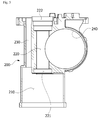
- FIG. 4 is a view illustrating a housing and a sealing cover which covers the housing
- FIG. 5 is a view illustrating an inside of the housing.
- the housing 200 may be partitioned to include a motor accommodation portion 210, a screw accommodation portion 220, a connecting terminal accommodation portion 230, and a worm wheel accommodation portion 240.
- the motor accommodation portion 210 is formed in a lower portion of the housing 200 and has an internal space in which the motor 310 is accommodated.
- the screw accommodation portion 220 is disposed above the motor accommodation portion 210 and communicates with the motor accommodation portion 210.
- the screw accommodation portion 220 provides a space which is formed to be vertically long with the screw 320 inserted thereinto.
- An inlet 221 of the screw accommodation portion 220 may be connected to the motor accommodation portion 210, and an outlet 222 thereof may be connected to a vehicle part such as a brake apparatus.
- the connecting terminal accommodation portion 230 is formed to be vertically long and has an accommodation space in which connectors 315 shown in FIG. 2 are positioned.
- a lower portion of the connecting terminal accommodation portion 230 may be connected to the motor accommodation portion 210, and an upper portion thereof may be formed in an open shape.
- the lower portion of the housing 200 may be open.
- a cover 201 is coupled to the open lower portion of the housing 200.
- the motor accommodation portion 210 is sealed with the cover 201.
- the worm wheel accommodation portion 240 communicates with the screw accommodation portion 220 and has an accommodation space for the worm wheel 330.
- the worm wheel 330 may be disposed at one side with respect to the screw accommodation portion 220, and the connecting terminal accommodation portion 230 may be disposed at the other side.
- the worm wheel 330 may be disposed in front of the screw accommodation portion 220, and the connecting terminal accommodation portion 230 may be disposed behind the screw accommodation portion 220.
- a brake oil or lubricating oil of a brake apparatus may flow into the screw accommodation portion 220 through the outlet 222 of the screw accommodation portion 220. Accordingly, it is necessary for the sealing cover 100 to seal the outlet 222 of the screw accommodation portion 220.
- FIG. 6 is a view illustrating a sealing cover according to a first modified embodiment
- FIG. 7 is a cross-sectional view illustrating the sealing cover shown in FIG. 6
- FIG. 8 is a bottom view illustrating the sealing cover shown in FIG. 6 .
- FIG. 6 is a view clearly illustrating only main features for a clear conceptual understanding of the present invention and the scope of the present invention is not limited to specific shapes illustrated in the drawing, and as a result various modifications should be expected.
- the sealing cover 100 may include a cap 110, a grommet 120, and terminals 130.
- the cap 110, the grommet 120, and the terminals 130 may be one part formed by injection molding.
- the cap 110 is a member which seals the screw accommodation portion 220 by covering the outlet 222 of the screw accommodation portion 220 and may be inserted into the outlet 222.
- the cap 110 may be formed as a cylindrical member to correspond to a shape of the outlet 222 and may be formed of an elastic material to increase adhesion.
- a sealing member 111 may be additionally installed along a circumference of the cap 110 to increase adhesion.
- the grommet 120 may extend from the cap 110 and be integrally formed with the cap 110. In consideration of shapes and positions of the terminals 130, the grommet 120 may be formed to extend in one direction with respect to the cap 110 and to extend to the other direction. Because the cap 110 and the grommet 120 are integrated and installed in a housing 200 as a single part, there is an advantage in that an assembly process which implements sealing of the housing 200 and an electrically connected structure is simplified.
- coupling flanges 125 may be respectively formed at both side surfaces of the grommet 120 at which first connecting ends 131 and second connecting ends 132 are positioned.
- the coupling flanges 125 are places into which coupling members, such as a screw, are inserted to be coupled to the housing 200.
- the terminals 130 are connected to busbars 313 of a motor 310.
- the terminals 130 may be inserted into the grommet 120.
- the terminals 130 may include the first connecting ends 131, the second connecting ends 132, and bodies 133.
- the first connecting ends 131 and the second connecting ends 132 may be disposed with the cap 110 interposed therebetween.
- the first connecting ends 131 may be disposed behind the cap 110, and the second connecting ends 132 may be disposed in front of the cap 110.
- connectors 315 in FIG. 2 are connected to the first connecting ends 131, and an external power source is connected to the second connecting ends 132.
- the bodies 133 are disposed along a circumference of the cap 110 and serve a function of connecting the first connecting ends 131 and the second connecting ends 132.
- the bodies 133 may be formed to have a curved surface and to be positioned along the circumference of the cap 110 having a cylindrical shape.
- terminal connecting holes 122 formed at positions of the first connecting ends 131 of the terminals 130 may be formed in the grommet 120.
- the connectors 315 in FIG. 2 extending from the busbars 313 pass through the terminal connecting holes 122 and are connected to the first connecting ends 131.
- FIG. 9 is a view illustrating terminals
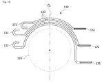
- FIG. 10 is a view illustrating positions of first connecting ends and second connecting ends of the terminals
- each of the terminals 130 may be disposed in a shape in which the bodies 133 are arranged in a radial direction of the cap 110.
- the first connecting ends 131 are disposed at a left side on the drawing and the second connecting ends 132 are disposed at a right side on the drawing, with respect to a virtual vertical base line CL passing through the center of the cap 110.
- positions of the first connecting ends 131 connected to the connectors 315 and positions of the second connecting ends 132 connected to an external power source are positioned to be maximally distant from each other, there are advantages in that a structure for assembly is simplified and structural stability is high.
- a structure in which the positions of the second connecting ends 132 connected to the external power source are positioned opposite the first connecting ends 131 in consideration of the connectors 315 that are formed to have long lengths greatly facilitates assemblability.
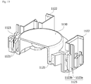
- FIG. 11 is a view illustrating a sealing cover according to a second modified embodiment.
- a grommet 1120 of a sealing cover 1000 according to the second modified embodiment may include grooves 1121.
- the grooves 1121 are grooves into which terminals 1130 are inserted.
- the grooves 1121 are formed to be recessed in a top surface of the grommet 1120 and have spaces into which the terminals 1130 are inserted.
- the sealing cover 1000 is formed so that the terminals 1130 are inserted into the grommet 1120 after a cap 1110 is mounted on the sealing cover 1000. This simplifies a manufacturing process and secures flexibility of the terminals 1130. To this end, the terminals 1130 are not included in the sealing cover 1000 according to the embodiment, but are implemented to be inserted into the sealing cover 1000 from an outside thereof through the grooves 1121.
- Each of the grooves 1121 is formed to connect one side and the other side of the groove 1121 which interpose the cap 1110. This is in consideration of shapes and positions of each of the terminals 1130.
- the grooves 1121 may be formed along a circumference of the cap 1110. Cross-sectional shapes of the grooves 1121 may be formed to correspond to those of the terminals 1130.
- the grooves 1121 may be formed to have rectangular cross-sections in consideration of cross-sections of the terminals 1130 having a shape of a thin plate.
- the grooves 1121 may be formed to be deeper than heights of the terminals 1130 such that the terminals 1130 inserted into the grooves 1121 are not exposed to an outside of the grommet 1120.
- the number of grooves 1121 may correspond to the number of terminals 1130. Total three grooves 1121 may be provided to correspond to three terminals 1130 connected to an U, V, and W-phase power source.
- Accommodation portions 1122 connected to the grooves 1121 may be respectively provided at end portions of the grooves 1121.
- the accommodation portions 1122 are formed to be recessed in the grommet 1120 and provide spaces in which external connectors connected to the terminals 1130 are accommodated.
- Fixing portions 1123 are provided at the grommet 1120 and serve a function of fixing the terminals 1130 such that the terminals 1130 inserted into the grooves 1121 do not escape from the grommet 1120.
- the fixing portions 1123 may be disposed adjacent to the grooves 1121 along paths of the grooves 1121.
- some of the fixing portions 1123 may be disposed at end portions of one sides of the grooves 1121 with respect to the cap 1110.
- the other fixing portions 1123 may be positioned at end portions of the other sides of the grooves 1121 with respect to the cap 1110.
- the fixing portions 1123 disposed at the both sides with respect to the cap 1110 respectively fix both end portions of the terminals 1130 inserted into the grooves 1121 and stably fix the grommet 1120 to the terminals 1130.
- FIG. 12 is a plan view illustrating the sealing cover shown in FIG. 11
- FIG. 13 is a cross-sectional view illustrating the sealing cover shown in FIG. 11 .
- the fixing portions 1123 may include columns 1123a and hooks 1123b.
- the columns 1123a protrude from the top surface of the grommet 1120.
- the hooks 1123b may be formed at ends of the columns 1123a.
- the hooks 1123b are disposed above the grooves 1121 and prevent the terminals 1130 inserted into the grooves 1121 from escaping the grooves 1121.
- Top surfaces of the hooks 1123b are formed to have inclined surfaces such that the terminals 1130 slide on the hooks 1123b and are easily inserted into the grooves 1121.
- the grommet 1120 may include terminal connecting holes 1124.
- the terminal connecting holes 1124 are formed to pass through the top surface and a bottom surface of the grommet 1120.
- the terminal connecting holes 1124 may be formed at one side of the cap 1110.
- the terminal connecting holes 1124 may be connected to ends of the grooves 1121.
- positions of the terminal connecting holes 1124 correspond to positions of connecting ends of the terminals 1130.
- the connectors 315 in FIG. 2 which extend from the busbars 313 pass through the terminal connecting holes 1124 and are connected to the connecting ends of the terminals 1130.
- the number of terminal connecting holes 1124 corresponds to the number of terminals 1130.
- Coupling flanges 1125 may be respectively formed at both side surfaces of the grommet 1120.
- the coupling flanges 1125 are places into which a coupling member, such as a screw, is inserted to be coupled with a housing 200.
- the terminals 1130 connect the busbars 313 of the motor 310 and an external power source.
- the terminals 1130 may be inserted into the grooves 1121 of the grommet 1120.
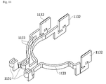
- FIG. 14 is a view illustrating terminals.
- the terminals 1130 may include first connecting ends 1131, second connecting ends 1132, and bodies 1133.
- the first connecting ends 1131 and the second connecting ends 1132 may be disposed with the cap 1110 interposed therebetween.
- the first connecting ends 1131 may be disposed behind the cap 1110, and the second connecting ends 1132 may be disposed in front of the cap 1110.
- the first connecting ends 1131 are portions to which the connectors 315 are connected
- the second connecting ends 1132 are portions to which an external power source is connected.
- the bodies 1133 are disposed along the circumference of the cap 1110 and serve a function of connecting the first connecting ends 1131 and the second connecting ends 1132.
- the bodies 1133 may be formed to have a curved surface and to be positioned along the circumference of the cap 1110 having a cylindrical shape.
- the three terminals 1130 configured to be connected to the U, V, and W-phase power source may be provided.
- Each of the terminals may be disposed in a shape in which the bodies 1133 are arranged in a radial direction of the cap 1110.
- the first connecting ends 1131 are disposed at a left side on the drawing and the second connecting ends 1132 are disposed at a right side on the drawing.
- positions of the first connecting ends 1131 connected to the connectors 315 and positions of the second connecting ends 1132 connected to the external power source are positioned to be maximum distant from each other, there are advantages in that a structure for assembly is simplified and structural stability is high.
- a structure in which the positions of the second connecting ends 1132 connected to the external power source are positioned opposite the first connecting ends 1131 in consideration of the connectors 315 formed to have a long length and connected to the first connecting ends 1131 increases assemblability and secures structural stability.
- Shapes of the above-described terminals 1130 correspond to shapes of the grooves 1121.
- an advantageous effect in that a structure for assembly of an actuator is simplified by providing a sealing cover in which a cap and a grommet are integrated is provided.
- a terminal is easily assembled with other parts of a vehicle by disposing a first connecting end of the terminal at one side with respect to a cap and disposing a second connecting end of the terminal at the other side with respect to the cap.
- advantageous effects are provided in that an assembly process is simplified and flexibility of terminals is secured by inserting the terminal into a grommet after mounting a cap on a housing.
Landscapes
- Engineering & Computer Science (AREA)
- Power Engineering (AREA)
- Motor Or Generator Frames (AREA)
- Connection Of Motors, Electrical Generators, Mechanical Devices, And The Like (AREA)
Abstract
Description
- This application claims priority to and the benefit of Korean Patent Application No.
2015-0148856, filed on October 26, 2015 2016-0070407, filed on June 7, 2016 - The present invention relates to a sealing cover and an actuator having the same.
- When a motor is connected to a vehicle part such as a brake apparatus, a brake oil and a lubricating oil used in the brake apparatus can flow into the motor. To prevent such a flow, a sealing cover may be provided at an end cover of the motor.
- However, a structure of such a sealing cover has a problem in that a structure for assembly is complex. Particularly, there is a problem in that positions of terminals become complex due to the sealing cover.
- The present invention is directed to a sealing cover having a simple structure for assembly and an actuator including the same.
- The scope of the present invention is not limited to the above-described objects, and other unmentioned objects may be clearly understood by those skilled in the art from the following descriptions
- According to an aspect of the present invention, there is provided a sealing cover including a cap, a grommet configured to extend from the cap, and a terminal inserted into the grommet.
- The terminal may include a first connecting end disposed at one side of the terminal and a second connecting end disposed at the other side with the cap interposed therebetween.
- The terminal may include a body disposed along a circumference of the cap and configured to connect the first connecting end and the second connecting end.
- The grommet may include a terminal connecting hole formed at a position of the first connecting end.
- The grommet may include coupling flanges respectively formed at positions of the first connecting end and the second connecting end.
- According to another aspect of the present invention, there is provided an actuator including a housing, a motor disposed in the housing, and a sealing cover including a cap configured to cover the housing, a grommet configured to extend from the cap, and a terminal inserted into the grommet and electrically connected to the motor.
- The motor may include a motor and a screw connected to the motor, and the housing may include a motor accommodation portion configured to accommodate the motor and a screw accommodation portion configured to communicate with the motor accommodation portion and accommodate the screw.
- The screw accommodation portion may include an inlet connected to the motor accommodation portion and an outlet open to an outside, and the cap may be coupled to the outlet.
- The motor may include a stator disposed inside the motor accommodation portion and having a coil wound therearound, a rotor disposed at an inner side of the stator, a shaft coupled to the rotor, and a busbar connected to the coil.
- The terminal may include a first connecting end disposed at one side of the terminal and a second connecting end disposed at the other side with the cap interposed therebetween.
- The motor may include a connecting terminal configured to connect the first connecting end and the busbar.
- The terminal may include a body disposed along a circumference of the cap and configured to connect the first connecting end and the second connecting end.
- The grommet may include a terminal connecting hole formed at a position of the first connecting end.
- The housing may include a connecting terminal accommodation portion configured to accommodate the connecting terminal.
- The motor part may include a worm wheel engaged with the screw.
- The housing may include a worm wheel accommodation portion configured to communicate with the screw accommodation portion.
- The terminal may include a first connecting end disposed at one side of the terminal and a second connecting end disposed at the other side with the cap interposed therebetween, the motor includes a connecting terminal configured to connect the first connecting end and the busbar, the housing includes a connecting terminal accommodation portion configured to accommodate the connecting terminal, and the worm wheel accommodation portion is disposed at one side and the connecting terminal accommodation portion is disposed at the other side with respect to the screw accommodation portion.
- The second connecting end may be disposed above the worm wheel accommodation portion.
- The grommet may include a groove formed to be recessed such that the terminal is inserted thereinto.
- According to still another aspect of the present invention, there is provided a sealing cover including a cap, a grommet configured to extend from the cap, and a terminal inserted into the grommet, wherein the grommet includes a groove formed to be recessed such that the terminal is inserted thereinto.
- The groove may be formed to be recessed in a top surface of the grommet.
- The groove may connect one side and the other side of the groove with the cap interposed therebetween.
- The groove may be disposed along a circumference of the cap.
- The grommet may include an accommodation portion formed to be recessed, connected to the groove, and configured to accommodate an external connector connected to a connecting end of the terminal.
- The grommet may include a fixing portion configured to protrude adjacent to the groove and fix the terminal inserted into the groove.
- The fixing portion may include a column configured to protrude from a top surface of the grommet and a hook formed at an end of the column and configured to restrict the terminal inserted into the groove.
- The above and other objects, features and advantages of the present invention will become more apparent to those of ordinary skill in the art by describing exemplary embodiments thereof in detail with reference to the accompanying drawings, in which:
-
FIG. 1 is a view illustrating an actuator according to an embodiment; -
FIG. 2 is a view illustrating a motor shown inFIG. 1 ; -
FIG. 3 is a view illustrating a position of a vehicle part to which the actuator shown inFIG. 1 is coupled; -
FIG. 4 is a view illustrating a housing and a sealing cover which covers the housing; -
FIG. 5 is a view illustrating an inside of the housing; -
FIG. 6 is a view illustrating a sealing cover according to a first modified embodiment; -
FIG. 7 is a cross-sectional view illustrating the sealing cover shown inFIG. 6 ; -
FIG. 8 is a bottom view illustrating the sealing cover shown inFIG. 6 ; -
FIG. 9 is a view illustrating terminals; -
FIG. 10 is a view illustrating positions of first connecting ends and second connecting ends of the terminals; -
FIG. 11 is a view illustrating a sealing cover according to a second modified embodiment; -
FIG. 12 is a plan view illustrating the sealing cover shown inFIG. 11 ; -
FIG. 13 is a cross-sectional view illustrating the sealing cover shown inFIG. 11 ; and -
FIG. 14 is a view illustrating terminals. - Hereinafter, an exemplary embodiment of the present invention will be described with reference to the accompanying drawings in detail. Purposes, specific advantages, and novel features of the invention will be made clear from exemplary embodiments and the following detailed description in connection with the accompanying drawings. Terms and words used in this specification and claims are not to be interpreted as limited to commonly used meanings or meanings in dictionaries, and should be interpreted as having meanings and concepts which are consistent with the technological scope of the invention based on the principle that the inventors have appropriately defined concepts of terms in order to describe the invention in the best way. In the description of the invention, when it is determined that detailed descriptions of related well-known functions unnecessarily obscure the gist of the invention, the detailed descriptions thereof will be omitted.
-
FIG. 1 is a view illustrating an actuator according to an embodiment, andFIG. 2 is a view illustrating a motor shown inFIG. 1. FIGS. 1 and2 are views clearly illustrating only main features for a clear conceptual understanding of the present invention, and the scope of the present invention is not limited to specific shapes illustrated in the drawings, and as a result, various modifications should be expected. - Referring to
FIGS. 1 and2 , the actuator according to the embodiment may include asealing cover 100, ahousing 200, and amotor 300. Thesealing cover 100 may be coupled to an upper portion of thehousing 200, and themotor 300 may be installed in thehousing 200. - The
motor 300 may include amotor 310 and ascrew 320. - The
motor 310 may include astator 311, arotor 312, andbusbars 313. - The
stator 311 is coupled to thehousing 200, and therotor 312 is disposed at an inner side of thestator 311. Thescrew 320 may be coupled to a central portion of therotor 312. Coils are wound around thestator 311 to have magnetic poles, and thus therotor 312 is rotated due to a magnetic field generated by the wound coils and thescrew 320 is rotated simultaneously therewith. - The
stator 311 may be formed to include a plurality of stator cores. For example, each of the stator cores may be formed by stacking a plurality of steel plates including a ring-shaped yoke and teeth disposed in a circumferential direction, protruding from the yoke in an inward direction of a diameter thereof, and having equal angular gaps. The coils may be wound around the teeth. Here, the coils may be insulated from each other by an insulator. - The
rotor 312 is disposed at the inner side of thestator 311. Therotor 312 may be formed by coupling a magnet to a rotor core, and the rotor core may also be integrally formed with the magnet in some cases. In addition, therotor 312 may be formed as a type in which the magnet is coupled to a circumferential surface of the rotor core or as a type in which the magnet is inserted into a pocket of the rotor core. - The
busbars 313 may be provided on thestator 311. Thebusbars 313 are for connecting the coils disposed in parallel and are electrically connected to the coils. Thebusbars 313 are provided with ring-shaped bodies formed of insulating materials, and the ring-shaped bodies are provided with terminals to be connected to the coils. In addition, thebusbars 313 may be connected to terminals and may supply electricity to the coils through power terminals which receive external power having polarities different from each other. - The
screw 320 is coupled to therotor 312. Thescrew 320 rotates in conjunction with rotation of therotor 312. Here, thescrew 320 may be a worm gear. - A
worm wheel 330 may be disposed to engage with thescrew 320. Theworm wheel 330 may rotate about awheel shaft 331 in conjunction with rotation of thescrew 320. Apinion gear 340 may be formed on thewheel shaft 331. Thepinion gear 340 rotates when theworm wheel 330 rotates, and thus a driving force necessary for a vehicle may be supplied by the rotation of thepinion gear 340. Here, the driving force necessary for a vehicle may be a force for braking, and thepinion gear 340 may be connected to a brake apparatus of a vehicle such that power is transmitted thereto. -
FIG. 3 is a view illustrating a position of a vehicle part to which the actuator shown inFIG. 1 is coupled. - Referring to
FIG. 3 , avehicle part 20, such as a brake apparatus, may be coupled to a top of anactuator 10. -
FIG. 4 is a view illustrating a housing and a sealing cover which covers the housing, andFIG. 5 is a view illustrating an inside of the housing. - Referring to
FIGS. 2 to 5 , thehousing 200 may be partitioned to include amotor accommodation portion 210, ascrew accommodation portion 220, a connectingterminal accommodation portion 230, and a wormwheel accommodation portion 240. - The
motor accommodation portion 210 is formed in a lower portion of thehousing 200 and has an internal space in which themotor 310 is accommodated. - The
screw accommodation portion 220 is disposed above themotor accommodation portion 210 and communicates with themotor accommodation portion 210. Thescrew accommodation portion 220 provides a space which is formed to be vertically long with thescrew 320 inserted thereinto. Aninlet 221 of thescrew accommodation portion 220 may be connected to themotor accommodation portion 210, and anoutlet 222 thereof may be connected to a vehicle part such as a brake apparatus. - The connecting
terminal accommodation portion 230 is formed to be vertically long and has an accommodation space in whichconnectors 315 shown inFIG. 2 are positioned. A lower portion of the connectingterminal accommodation portion 230 may be connected to themotor accommodation portion 210, and an upper portion thereof may be formed in an open shape. - The lower portion of the
housing 200 may be open. Acover 201 is coupled to the open lower portion of thehousing 200. Themotor accommodation portion 210 is sealed with thecover 201. - The worm
wheel accommodation portion 240 communicates with thescrew accommodation portion 220 and has an accommodation space for theworm wheel 330. - The
worm wheel 330 may be disposed at one side with respect to thescrew accommodation portion 220, and the connectingterminal accommodation portion 230 may be disposed at the other side. For example, theworm wheel 330 may be disposed in front of thescrew accommodation portion 220, and the connectingterminal accommodation portion 230 may be disposed behind thescrew accommodation portion 220. - Meanwhile, a brake oil or lubricating oil of a brake apparatus may flow into the
screw accommodation portion 220 through theoutlet 222 of thescrew accommodation portion 220. Accordingly, it is necessary for the sealingcover 100 to seal theoutlet 222 of thescrew accommodation portion 220. -
FIG. 6 is a view illustrating a sealing cover according to a first modified embodiment,FIG. 7 is a cross-sectional view illustrating the sealing cover shown inFIG. 6 , andFIG. 8 is a bottom view illustrating the sealing cover shown inFIG. 6 . Here,FIG. 6 is a view clearly illustrating only main features for a clear conceptual understanding of the present invention and the scope of the present invention is not limited to specific shapes illustrated in the drawing, and as a result various modifications should be expected. - Referring to
FIGS. 6 to 8 , the sealingcover 100 may include acap 110, agrommet 120, andterminals 130. Thecap 110, thegrommet 120, and theterminals 130 may be one part formed by injection molding. - The
cap 110 is a member which seals thescrew accommodation portion 220 by covering theoutlet 222 of thescrew accommodation portion 220 and may be inserted into theoutlet 222. Thecap 110 may be formed as a cylindrical member to correspond to a shape of theoutlet 222 and may be formed of an elastic material to increase adhesion. In addition, a sealingmember 111 may be additionally installed along a circumference of thecap 110 to increase adhesion. - The
grommet 120 may extend from thecap 110 and be integrally formed with thecap 110. In consideration of shapes and positions of theterminals 130, thegrommet 120 may be formed to extend in one direction with respect to thecap 110 and to extend to the other direction. Because thecap 110 and thegrommet 120 are integrated and installed in ahousing 200 as a single part, there is an advantage in that an assembly process which implements sealing of thehousing 200 and an electrically connected structure is simplified. - Meanwhile,
coupling flanges 125 may be respectively formed at both side surfaces of thegrommet 120 at which first connecting ends 131 and second connecting ends 132 are positioned. Thecoupling flanges 125 are places into which coupling members, such as a screw, are inserted to be coupled to thehousing 200. - The
terminals 130 are connected tobusbars 313 of amotor 310. Theterminals 130 may be inserted into thegrommet 120. In addition, theterminals 130 may include the first connecting ends 131, the second connecting ends 132, andbodies 133. - The first connecting ends 131 and the second connecting ends 132 may be disposed with the
cap 110 interposed therebetween. For example, the first connecting ends 131 may be disposed behind thecap 110, and the second connecting ends 132 may be disposed in front of thecap 110. Here,connectors 315 inFIG. 2 are connected to the first connecting ends 131, and an external power source is connected to the second connecting ends 132. - The
bodies 133 are disposed along a circumference of thecap 110 and serve a function of connecting the first connecting ends 131 and the second connecting ends 132. Thebodies 133 may be formed to have a curved surface and to be positioned along the circumference of thecap 110 having a cylindrical shape. - As illustrated in
FIG. 8 ,terminal connecting holes 122 formed at positions of the first connecting ends 131 of theterminals 130 may be formed in thegrommet 120. Theconnectors 315 inFIG. 2 extending from thebusbars 313 pass through theterminal connecting holes 122 and are connected to the first connecting ends 131. -
FIG. 9 is a view illustrating terminals, andFIG. 10 is a view illustrating positions of first connecting ends and second connecting ends of the terminals; - Referring to
FIGS. 9 and10 , threeterminals 130 configured to be respectively connected to an U, V, and W-phase power source may be provided. Each of theterminals 130 may be disposed in a shape in which thebodies 133 are arranged in a radial direction of thecap 110. As a result, the first connecting ends 131 are disposed at a left side on the drawing and the second connecting ends 132 are disposed at a right side on the drawing, with respect to a virtual vertical base line CL passing through the center of thecap 110. - Because positions of the first connecting ends 131 connected to the
connectors 315 and positions of the second connecting ends 132 connected to an external power source are positioned to be maximally distant from each other, there are advantages in that a structure for assembly is simplified and structural stability is high. A structure in which the positions of the second connecting ends 132 connected to the external power source are positioned opposite the first connecting ends 131 in consideration of theconnectors 315 that are formed to have long lengths greatly facilitates assemblability. -
FIG. 11 is a view illustrating a sealing cover according to a second modified embodiment. - Referring to
FIG. 11 , agrommet 1120 of a sealingcover 1000 according to the second modified embodiment may includegrooves 1121. - The
grooves 1121 are grooves into whichterminals 1130 are inserted. Thegrooves 1121 are formed to be recessed in a top surface of thegrommet 1120 and have spaces into which theterminals 1130 are inserted. The sealingcover 1000 is formed so that theterminals 1130 are inserted into thegrommet 1120 after acap 1110 is mounted on the sealingcover 1000. This simplifies a manufacturing process and secures flexibility of theterminals 1130. To this end, theterminals 1130 are not included in the sealingcover 1000 according to the embodiment, but are implemented to be inserted into the sealingcover 1000 from an outside thereof through thegrooves 1121. - Each of the
grooves 1121 is formed to connect one side and the other side of thegroove 1121 which interpose thecap 1110. This is in consideration of shapes and positions of each of theterminals 1130. In addition, thegrooves 1121 may be formed along a circumference of thecap 1110. Cross-sectional shapes of thegrooves 1121 may be formed to correspond to those of theterminals 1130. For example, thegrooves 1121 may be formed to have rectangular cross-sections in consideration of cross-sections of theterminals 1130 having a shape of a thin plate. Thegrooves 1121 may be formed to be deeper than heights of theterminals 1130 such that theterminals 1130 inserted into thegrooves 1121 are not exposed to an outside of thegrommet 1120. - The number of
grooves 1121 may correspond to the number ofterminals 1130. Total threegrooves 1121 may be provided to correspond to threeterminals 1130 connected to an U, V, and W-phase power source. -
Accommodation portions 1122 connected to thegrooves 1121 may be respectively provided at end portions of thegrooves 1121. Theaccommodation portions 1122 are formed to be recessed in thegrommet 1120 and provide spaces in which external connectors connected to theterminals 1130 are accommodated. - Fixing
portions 1123 are provided at thegrommet 1120 and serve a function of fixing theterminals 1130 such that theterminals 1130 inserted into thegrooves 1121 do not escape from thegrommet 1120. The fixingportions 1123 may be disposed adjacent to thegrooves 1121 along paths of thegrooves 1121. For example, some of the fixingportions 1123 may be disposed at end portions of one sides of thegrooves 1121 with respect to thecap 1110. In addition, theother fixing portions 1123 may be positioned at end portions of the other sides of thegrooves 1121 with respect to thecap 1110. - As a result, the fixing
portions 1123 disposed at the both sides with respect to thecap 1110 respectively fix both end portions of theterminals 1130 inserted into thegrooves 1121 and stably fix thegrommet 1120 to theterminals 1130. -
FIG. 12 is a plan view illustrating the sealing cover shown inFIG. 11 , andFIG. 13 is a cross-sectional view illustrating the sealing cover shown inFIG. 11 . - Referring to
FIGS. 12 and13 , the fixingportions 1123 may includecolumns 1123a and hooks 1123b. Thecolumns 1123a protrude from the top surface of thegrommet 1120. Thehooks 1123b may be formed at ends of thecolumns 1123a. Thehooks 1123b are disposed above thegrooves 1121 and prevent theterminals 1130 inserted into thegrooves 1121 from escaping thegrooves 1121. Top surfaces of thehooks 1123b are formed to have inclined surfaces such that theterminals 1130 slide on thehooks 1123b and are easily inserted into thegrooves 1121. - As illustrated in
FIG. 12 , thegrommet 1120 may include terminal connectingholes 1124. Theterminal connecting holes 1124 are formed to pass through the top surface and a bottom surface of thegrommet 1120. Theterminal connecting holes 1124 may be formed at one side of thecap 1110. For example, theterminal connecting holes 1124 may be connected to ends of thegrooves 1121. In addition, positions of theterminal connecting holes 1124 correspond to positions of connecting ends of theterminals 1130. Theconnectors 315 inFIG. 2 which extend from thebusbars 313 pass through theterminal connecting holes 1124 and are connected to the connecting ends of theterminals 1130. - The number of terminal connecting
holes 1124 corresponds to the number ofterminals 1130. -
Coupling flanges 1125 may be respectively formed at both side surfaces of thegrommet 1120. Thecoupling flanges 1125 are places into which a coupling member, such as a screw, is inserted to be coupled with ahousing 200. - The
terminals 1130 connect thebusbars 313 of themotor 310 and an external power source. Theterminals 1130 may be inserted into thegrooves 1121 of thegrommet 1120. -
FIG. 14 is a view illustrating terminals. - Referring to
FIG. 14 , theterminals 1130 may include first connecting ends 1131, second connecting ends 1132, andbodies 1133. The first connecting ends 1131 and the second connecting ends 1132 may be disposed with thecap 1110 interposed therebetween. For example, the first connecting ends 1131 may be disposed behind thecap 1110, and the second connecting ends 1132 may be disposed in front of thecap 1110. Here, the first connecting ends 1131 are portions to which theconnectors 315 are connected, and the second connecting ends 1132 are portions to which an external power source is connected. - The
bodies 1133 are disposed along the circumference of thecap 1110 and serve a function of connecting the first connecting ends 1131 and the second connecting ends 1132. Thebodies 1133 may be formed to have a curved surface and to be positioned along the circumference of thecap 1110 having a cylindrical shape. - The three
terminals 1130 configured to be connected to the U, V, and W-phase power source may be provided. Each of the terminals may be disposed in a shape in which thebodies 1133 are arranged in a radial direction of thecap 1110. As a result, the first connecting ends 1131 are disposed at a left side on the drawing and the second connecting ends 1132 are disposed at a right side on the drawing. - Because positions of the first connecting ends 1131 connected to the
connectors 315 and positions of the second connecting ends 1132 connected to the external power source are positioned to be maximum distant from each other, there are advantages in that a structure for assembly is simplified and structural stability is high. - A structure in which the positions of the second connecting ends 1132 connected to the external power source are positioned opposite the first connecting ends 1131 in consideration of the
connectors 315 formed to have a long length and connected to the first connecting ends 1131 increases assemblability and secures structural stability. - Shapes of the above-described
terminals 1130 correspond to shapes of thegrooves 1121. - The sealing cover and the actuator including the same according to one exemplary embodiment of the present invention have been specifically described above with reference to the accompanying drawings.
- As described above, according to the embodiment, an advantageous effect in that a structure for assembly of an actuator is simplified by providing a sealing cover in which a cap and a grommet are integrated is provided.
- According to the embodiment, an advantageous effect is provided in that a terminal is easily assembled with other parts of a vehicle by disposing a first connecting end of the terminal at one side with respect to a cap and disposing a second connecting end of the terminal at the other side with respect to the cap.
- According to the embodiment, advantageous effects are provided in that an assembly process is simplified and flexibility of terminals is secured by inserting the terminal into a grommet after mounting a cap on a housing.
- While the present invention has been particularly described with reference to exemplary embodiments, those of skilled in the art should understand that various changes in form and details may be made without departing from the spirit and scope of the present invention. Therefore, the exemplary embodiments should be considered in a descriptive sense only and not for purposes of limitation. The scope of the invention is defined not by the detailed description of the invention but by the appended claims, and encompasses all modifications and equivalents that fall within the scope of the appended claims.
-
- 100, 1000:
- SEALING COVER
- 110, 1110:
- CAP
- 120, 1120:
- GROMMET
- 1121:
- GROOVE
- 122, 1122:
- ACCOMMODATION PORTION
- 123, 1123:
- FIXING PORTION
- 124, 1124:
- TERMINAL CONNECTING HOLE
- 125, 1125:
- COUPLING FLANGE
- 130, 1130:
- TERMINAL
- 200:
- HOUSING
- 210:
- MOTOR ACCOMMODATION PORTION
- 220:
- SCREW ACCOMMODATION PORTION
- 221:
- INLET
- 222:
- OUTLET
- 230:
- CONNECTING TERMINAL ACCOMMODATION PORTION
- 240:
- WORM WHEEL ACCOMMODATION PORTION
- 300:
- MOTOR
- 310:
- MOTOR
- 311:
- STATOR
- 312:
- ROTOR
- 313:
- BUSBAR
- 320:
- SCREW
- 330:
- WORM WHEEL
- 331:
- WHEEL SHAFT
- 340:
- PINION GEAR
Claims (15)
- A sealing cover (100, 1000) comprising:a cap (110, 1100);a grommet (120, 1120) configured to extend from the cap (110, 1100); anda terminal (130, 1130) inserted into the grommet (120, 1120).
- The sealing cover (100, 1000) of claim 1, wherein the terminal (130, 1130) includes a first connecting end (131, 1131) disposed at one side of the terminal (130, 1130) and a second connecting end (132, 1132) disposed at the other side with the cap (110, 1100) interposed therebetween.
- The sealing cover (100, 1000) of claim 2, wherein the terminal (130, 1130) includes a body (133, 1133) disposed along a circumference of the cap (110, 1100) and configured to connect the first connecting end (131, 1131) and the second connecting end (132, 1132).
- The sealing cover (100, 1000) of claim 3, wherein the grommet (120, 1120) includes a terminal (130, 1130) connecting hole (1124) formed at a position of the first connecting end (131, 1131).
- The sealing cover (100, 1000) of claim 4, wherein the grommet (120, 1120) includes coupling flanges (125, 1125) respectively formed at positions of the first connecting end (131, 1131) and the second connecting end (132, 1132).
- The sealing cover (100, 1000) of claim 1, wherein the grommet (120, 1120) includes a groove (1121) formed to be recessed such that the terminal (130, 1130) is inserted thereinto.
- The sealing cover (100, 1000) of claim 6, wherein the groove (1121) is formed to be recessed in a top surface of the grommet (120, 1120).
- The sealing cover (100, 1000) of claim 7, wherein the groove (1121) connects one side and the other side of the groove (1121) with the cap (110, 1100) interposed therebetween.
- The sealing cover (100, 1000) of claim 8, wherein the groove (1121) is disposed along a circumference of the cap (110, 1100).
- The sealing cover (100, 1000) of claim 6, wherein the grommet (120, 1120) includes an accommodation portion (1122) formed to be recessed, connected to the groove (1121), and configured to accommodate an external connector connected to a connecting end of the terminal (130, 1130).
- The sealing cover (100, 1000) of claim 6, wherein the grommet (120, 1120) includes a fixing portion (1123) configured to protrude adjacent to the groove (1121) and fix the terminal (130, 1130) inserted into the groove (1121).
- The sealing cover (100, 1000) of claim 6, wherein the fixing portion (1123) includes a column (1123a) configured to protrude from a top surface of the grommet (120, 1120) and a hook (1123b) formed at an end of the column (1123a) and configured to restrict the terminal (130, 1130) inserted into the groove (1121).
- An actuator comprising:a housing (200);a motor (300) disposed in the housing (200); anda sealing cover (100, 1000) including a cap (110, 1100) configured to cover the housing (200), a grommet (120, 1120) configured to extend from the cap (110, 1100), and a terminal (130, 1130) inserted into the grommet (120, 1120) and electrically connected to the motor (300).
- The actuator of claim 13, wherein:the motor (300) includes a motor (310) and a screw (320) connected to the motor (310); andthe housing (200) includes a motor accommodation portion (210) configured to accommodate the motor and a screw accommodation portion (220) configured to communicate with the motor accommodation portion (210) and accommodate the screw (320).
- The actuator of claim 14, wherein:the screw accommodation portion (220) includes an inlet (221) connected to the motor accommodation portion (210) and an outlet (222) open to an outside; andthe cap (110, 1100) is coupled to the outlet (222).
Applications Claiming Priority (2)
| Application Number | Priority Date | Filing Date | Title |
|---|---|---|---|
| KR1020150148856A KR102504573B1 (en) | 2015-10-26 | 2015-10-26 | Sealing cover and actuator having the same |
| KR1020160070407A KR102580680B1 (en) | 2016-06-07 | 2016-06-07 | Sealing cover and actuator having the same |
Publications (2)
| Publication Number | Publication Date |
|---|---|
| EP3163719A1 true EP3163719A1 (en) | 2017-05-03 |
| EP3163719B1 EP3163719B1 (en) | 2020-07-15 |
Family
ID=57280970
Family Applications (1)
| Application Number | Title | Priority Date | Filing Date |
|---|---|---|---|
| EP16195626.3A Active EP3163719B1 (en) | 2015-10-26 | 2016-10-25 | Sealing cover and actuator having same |
Country Status (3)
| Country | Link |
|---|---|
| US (1) | US10431921B2 (en) |
| EP (1) | EP3163719B1 (en) |
| CN (1) | CN106849488B (en) |
Families Citing this family (2)
| Publication number | Priority date | Publication date | Assignee | Title |
|---|---|---|---|---|
| CN109471030A (en) * | 2018-12-28 | 2019-03-15 | 天津市百成油田采油设备制造有限公司 | A submersible pump motor horizontal test test cap |
| JP7211258B2 (en) * | 2019-05-17 | 2023-01-24 | 株式会社デンソー | drive |
Citations (11)
| Publication number | Priority date | Publication date | Assignee | Title |
|---|---|---|---|---|
| GB2221102A (en) * | 1988-07-15 | 1990-01-24 | Asmo Co Ltd | A small motor end frame has various positions for terminal attachment |
| US5086243A (en) * | 1989-08-25 | 1992-02-04 | Siemens Aktiengesellschaft | Rotation detector for a commutator motor excited by pole units |
| US5280210A (en) * | 1987-12-30 | 1994-01-18 | Kress-Elektric Gmbh & Co. Elektromotorenfabrik | Universal electric motor with a switch ring mounted adjacent the brushes |
| JPH07322556A (en) * | 1994-05-25 | 1995-12-08 | Mitsubishi Electric Corp | Vehicle generator |
| WO2005077017A2 (en) * | 2004-02-06 | 2005-08-25 | Motor Products Corporation | Improved brush card apparatus and method |
| EP1677404A2 (en) * | 2004-12-28 | 2006-07-05 | Hitachi, Ltd. | Motor for electric power steering and method for manufacturing the same |
| US20080284265A1 (en) * | 2007-05-17 | 2008-11-20 | Vision Global Trading, Inc. | Water-resistant electric motor |
| US20120223604A1 (en) * | 2011-03-01 | 2012-09-06 | Robert Bosch Gmbh | Connecting Element Between a Motor and a Control Unit |
| JP2012186919A (en) * | 2011-03-04 | 2012-09-27 | Asmo Co Ltd | Motor |
| EP2849315A2 (en) * | 2013-09-16 | 2015-03-18 | LG Innotek Co., Ltd. | Bus bar and motor including the same |
| US20150180299A1 (en) * | 2013-12-24 | 2015-06-25 | Minebea Co., Ltd. | Dc brush motor |
Family Cites Families (4)
| Publication number | Priority date | Publication date | Assignee | Title |
|---|---|---|---|---|
| US5144738A (en) | 1991-04-29 | 1992-09-08 | Ford Motor Company | Automatic retention adjustment of motor armature assembly |
| GB9812844D0 (en) * | 1998-06-16 | 1998-08-12 | Lucas Ind Plc | Improvements relating to electrical power assisted steering |
| JP2004056895A (en) * | 2002-07-18 | 2004-02-19 | Mitsuba Corp | Electric motor |
| JP5759719B2 (en) * | 2010-12-28 | 2015-08-05 | アスモ株式会社 | Brush motor with reduction gear |
-
2016
- 2016-10-25 EP EP16195626.3A patent/EP3163719B1/en active Active
- 2016-10-25 US US15/333,570 patent/US10431921B2/en active Active
- 2016-10-26 CN CN201610945506.9A patent/CN106849488B/en active Active
Patent Citations (11)
| Publication number | Priority date | Publication date | Assignee | Title |
|---|---|---|---|---|
| US5280210A (en) * | 1987-12-30 | 1994-01-18 | Kress-Elektric Gmbh & Co. Elektromotorenfabrik | Universal electric motor with a switch ring mounted adjacent the brushes |
| GB2221102A (en) * | 1988-07-15 | 1990-01-24 | Asmo Co Ltd | A small motor end frame has various positions for terminal attachment |
| US5086243A (en) * | 1989-08-25 | 1992-02-04 | Siemens Aktiengesellschaft | Rotation detector for a commutator motor excited by pole units |
| JPH07322556A (en) * | 1994-05-25 | 1995-12-08 | Mitsubishi Electric Corp | Vehicle generator |
| WO2005077017A2 (en) * | 2004-02-06 | 2005-08-25 | Motor Products Corporation | Improved brush card apparatus and method |
| EP1677404A2 (en) * | 2004-12-28 | 2006-07-05 | Hitachi, Ltd. | Motor for electric power steering and method for manufacturing the same |
| US20080284265A1 (en) * | 2007-05-17 | 2008-11-20 | Vision Global Trading, Inc. | Water-resistant electric motor |
| US20120223604A1 (en) * | 2011-03-01 | 2012-09-06 | Robert Bosch Gmbh | Connecting Element Between a Motor and a Control Unit |
| JP2012186919A (en) * | 2011-03-04 | 2012-09-27 | Asmo Co Ltd | Motor |
| EP2849315A2 (en) * | 2013-09-16 | 2015-03-18 | LG Innotek Co., Ltd. | Bus bar and motor including the same |
| US20150180299A1 (en) * | 2013-12-24 | 2015-06-25 | Minebea Co., Ltd. | Dc brush motor |
Also Published As
| Publication number | Publication date |
|---|---|
| CN106849488A (en) | 2017-06-13 |
| US20170117653A1 (en) | 2017-04-27 |
| EP3163719B1 (en) | 2020-07-15 |
| US10431921B2 (en) | 2019-10-01 |
| CN106849488B (en) | 2020-06-26 |
Similar Documents
| Publication | Publication Date | Title |
|---|---|---|
| US11522405B2 (en) | Motor | |
| US8562313B2 (en) | Pump assembly | |
| US20200106319A1 (en) | A busbar unit for a stator of an electric motor | |
| US9385571B2 (en) | Stator member | |
| CN110268602B (en) | Electric motor and pump unit | |
| US10760572B2 (en) | Pump device | |
| JP6519241B2 (en) | DC motor | |
| CN107925303A (en) | Motor | |
| CN105960747A (en) | Rotary electric machine stator | |
| KR20170003103A (en) | Insulator and Motor having the same | |
| WO2018150964A1 (en) | Motor and pump device | |
| CN107404172B (en) | Insulating member for motor | |
| CN109301978B (en) | Motor and pump device | |
| CN109923765B (en) | Cover assembly and motor including the same | |
| EP3550701A1 (en) | Cover assembly, motor and electric steering device including same | |
| CN109716628A (en) | Motor | |
| CN112615454B (en) | Motor wiring device and actuator having the motor wiring device | |
| US10431921B2 (en) | Sealing cover and actuator having same | |
| CN108702055A (en) | motor | |
| KR102504573B1 (en) | Sealing cover and actuator having the same | |
| KR20170050928A (en) | Flange and Motor having the same | |
| CN107636938A (en) | The stator with termination and the motor with this stator of motor | |
| CN109792186A (en) | Motor | |
| CN109672275B (en) | Stator structure and rotary transformer | |
| CN104412495B (en) | Stator structure |
Legal Events
| Date | Code | Title | Description |
|---|---|---|---|
| PUAI | Public reference made under article 153(3) epc to a published international application that has entered the european phase |
Free format text: ORIGINAL CODE: 0009012 |
|
| STAA | Information on the status of an ep patent application or granted ep patent |
Free format text: STATUS: THE APPLICATION HAS BEEN PUBLISHED |
|
| AK | Designated contracting states |
Kind code of ref document: A1 Designated state(s): AL AT BE BG CH CY CZ DE DK EE ES FI FR GB GR HR HU IE IS IT LI LT LU LV MC MK MT NL NO PL PT RO RS SE SI SK SM TR |
|
| AX | Request for extension of the european patent |
Extension state: BA ME |
|
| RAP1 | Party data changed (applicant data changed or rights of an application transferred) |
Owner name: LG INNOTEK CO., LTD. |
|
| STAA | Information on the status of an ep patent application or granted ep patent |
Free format text: STATUS: REQUEST FOR EXAMINATION WAS MADE |
|
| 17P | Request for examination filed |
Effective date: 20171012 |
|
| RBV | Designated contracting states (corrected) |
Designated state(s): AL AT BE BG CH CY CZ DE DK EE ES FI FR GB GR HR HU IE IS IT LI LT LU LV MC MK MT NL NO PL PT RO RS SE SI SK SM TR |
|
| STAA | Information on the status of an ep patent application or granted ep patent |
Free format text: STATUS: EXAMINATION IS IN PROGRESS |
|
| 17Q | First examination report despatched |
Effective date: 20171213 |
|
| GRAP | Despatch of communication of intention to grant a patent |
Free format text: ORIGINAL CODE: EPIDOSNIGR1 |
|
| STAA | Information on the status of an ep patent application or granted ep patent |
Free format text: STATUS: GRANT OF PATENT IS INTENDED |
|
| RIC1 | Information provided on ipc code assigned before grant |
Ipc: H02K 7/116 20060101ALI20200107BHEP Ipc: H02K 5/22 20060101ALI20200107BHEP Ipc: H02K 3/52 20060101ALN20200107BHEP Ipc: H02K 5/10 20060101AFI20200107BHEP |
|
| INTG | Intention to grant announced |
Effective date: 20200205 |
|
| GRAS | Grant fee paid |
Free format text: ORIGINAL CODE: EPIDOSNIGR3 |
|
| GRAA | (expected) grant |
Free format text: ORIGINAL CODE: 0009210 |
|
| STAA | Information on the status of an ep patent application or granted ep patent |
Free format text: STATUS: THE PATENT HAS BEEN GRANTED |
|
| AK | Designated contracting states |
Kind code of ref document: B1 Designated state(s): AL AT BE BG CH CY CZ DE DK EE ES FI FR GB GR HR HU IE IS IT LI LT LU LV MC MK MT NL NO PL PT RO RS SE SI SK SM TR |
|
| REG | Reference to a national code |
Ref country code: CH Ref legal event code: EP Ref country code: GB Ref legal event code: FG4D |
|
| REG | Reference to a national code |
Ref country code: DE Ref legal event code: R096 Ref document number: 602016039884 Country of ref document: DE |
|
| REG | Reference to a national code |
Ref country code: IE Ref legal event code: FG4D |
|
| REG | Reference to a national code |
Ref country code: AT Ref legal event code: REF Ref document number: 1292068 Country of ref document: AT Kind code of ref document: T Effective date: 20200815 |
|
| REG | Reference to a national code |
Ref country code: LT Ref legal event code: MG4D |
|
| REG | Reference to a national code |
Ref country code: AT Ref legal event code: MK05 Ref document number: 1292068 Country of ref document: AT Kind code of ref document: T Effective date: 20200715 |
|
| REG | Reference to a national code |
Ref country code: NL Ref legal event code: MP Effective date: 20200715 |
|
| PG25 | Lapsed in a contracting state [announced via postgrant information from national office to epo] |
Ref country code: BG Free format text: LAPSE BECAUSE OF FAILURE TO SUBMIT A TRANSLATION OF THE DESCRIPTION OR TO PAY THE FEE WITHIN THE PRESCRIBED TIME-LIMIT Effective date: 20201015 Ref country code: SE Free format text: LAPSE BECAUSE OF FAILURE TO SUBMIT A TRANSLATION OF THE DESCRIPTION OR TO PAY THE FEE WITHIN THE PRESCRIBED TIME-LIMIT Effective date: 20200715 Ref country code: NO Free format text: LAPSE BECAUSE OF FAILURE TO SUBMIT A TRANSLATION OF THE DESCRIPTION OR TO PAY THE FEE WITHIN THE PRESCRIBED TIME-LIMIT Effective date: 20201015 Ref country code: GR Free format text: LAPSE BECAUSE OF FAILURE TO SUBMIT A TRANSLATION OF THE DESCRIPTION OR TO PAY THE FEE WITHIN THE PRESCRIBED TIME-LIMIT Effective date: 20201016 Ref country code: HR Free format text: LAPSE BECAUSE OF FAILURE TO SUBMIT A TRANSLATION OF THE DESCRIPTION OR TO PAY THE FEE WITHIN THE PRESCRIBED TIME-LIMIT Effective date: 20200715 Ref country code: AT Free format text: LAPSE BECAUSE OF FAILURE TO SUBMIT A TRANSLATION OF THE DESCRIPTION OR TO PAY THE FEE WITHIN THE PRESCRIBED TIME-LIMIT Effective date: 20200715 Ref country code: PT Free format text: LAPSE BECAUSE OF FAILURE TO SUBMIT A TRANSLATION OF THE DESCRIPTION OR TO PAY THE FEE WITHIN THE PRESCRIBED TIME-LIMIT Effective date: 20201116 Ref country code: ES Free format text: LAPSE BECAUSE OF FAILURE TO SUBMIT A TRANSLATION OF THE DESCRIPTION OR TO PAY THE FEE WITHIN THE PRESCRIBED TIME-LIMIT Effective date: 20200715 Ref country code: LT Free format text: LAPSE BECAUSE OF FAILURE TO SUBMIT A TRANSLATION OF THE DESCRIPTION OR TO PAY THE FEE WITHIN THE PRESCRIBED TIME-LIMIT Effective date: 20200715 Ref country code: FI Free format text: LAPSE BECAUSE OF FAILURE TO SUBMIT A TRANSLATION OF THE DESCRIPTION OR TO PAY THE FEE WITHIN THE PRESCRIBED TIME-LIMIT Effective date: 20200715 |
|
| PG25 | Lapsed in a contracting state [announced via postgrant information from national office to epo] |
Ref country code: LV Free format text: LAPSE BECAUSE OF FAILURE TO SUBMIT A TRANSLATION OF THE DESCRIPTION OR TO PAY THE FEE WITHIN THE PRESCRIBED TIME-LIMIT Effective date: 20200715 Ref country code: RS Free format text: LAPSE BECAUSE OF FAILURE TO SUBMIT A TRANSLATION OF THE DESCRIPTION OR TO PAY THE FEE WITHIN THE PRESCRIBED TIME-LIMIT Effective date: 20200715 Ref country code: PL Free format text: LAPSE BECAUSE OF FAILURE TO SUBMIT A TRANSLATION OF THE DESCRIPTION OR TO PAY THE FEE WITHIN THE PRESCRIBED TIME-LIMIT Effective date: 20200715 Ref country code: IS Free format text: LAPSE BECAUSE OF FAILURE TO SUBMIT A TRANSLATION OF THE DESCRIPTION OR TO PAY THE FEE WITHIN THE PRESCRIBED TIME-LIMIT Effective date: 20201115 |
|
| PG25 | Lapsed in a contracting state [announced via postgrant information from national office to epo] |
Ref country code: NL Free format text: LAPSE BECAUSE OF FAILURE TO SUBMIT A TRANSLATION OF THE DESCRIPTION OR TO PAY THE FEE WITHIN THE PRESCRIBED TIME-LIMIT Effective date: 20200715 |
|
| REG | Reference to a national code |
Ref country code: DE Ref legal event code: R097 Ref document number: 602016039884 Country of ref document: DE |
|
| PG25 | Lapsed in a contracting state [announced via postgrant information from national office to epo] |
Ref country code: CZ Free format text: LAPSE BECAUSE OF FAILURE TO SUBMIT A TRANSLATION OF THE DESCRIPTION OR TO PAY THE FEE WITHIN THE PRESCRIBED TIME-LIMIT Effective date: 20200715 Ref country code: DK Free format text: LAPSE BECAUSE OF FAILURE TO SUBMIT A TRANSLATION OF THE DESCRIPTION OR TO PAY THE FEE WITHIN THE PRESCRIBED TIME-LIMIT Effective date: 20200715 Ref country code: SM Free format text: LAPSE BECAUSE OF FAILURE TO SUBMIT A TRANSLATION OF THE DESCRIPTION OR TO PAY THE FEE WITHIN THE PRESCRIBED TIME-LIMIT Effective date: 20200715 Ref country code: RO Free format text: LAPSE BECAUSE OF FAILURE TO SUBMIT A TRANSLATION OF THE DESCRIPTION OR TO PAY THE FEE WITHIN THE PRESCRIBED TIME-LIMIT Effective date: 20200715 Ref country code: IT Free format text: LAPSE BECAUSE OF FAILURE TO SUBMIT A TRANSLATION OF THE DESCRIPTION OR TO PAY THE FEE WITHIN THE PRESCRIBED TIME-LIMIT Effective date: 20200715 Ref country code: EE Free format text: LAPSE BECAUSE OF FAILURE TO SUBMIT A TRANSLATION OF THE DESCRIPTION OR TO PAY THE FEE WITHIN THE PRESCRIBED TIME-LIMIT Effective date: 20200715 |
|
| PLBE | No opposition filed within time limit |
Free format text: ORIGINAL CODE: 0009261 |
|
| STAA | Information on the status of an ep patent application or granted ep patent |
Free format text: STATUS: NO OPPOSITION FILED WITHIN TIME LIMIT |
|
| PG25 | Lapsed in a contracting state [announced via postgrant information from national office to epo] |
Ref country code: AL Free format text: LAPSE BECAUSE OF FAILURE TO SUBMIT A TRANSLATION OF THE DESCRIPTION OR TO PAY THE FEE WITHIN THE PRESCRIBED TIME-LIMIT Effective date: 20200715 |
|
| REG | Reference to a national code |
Ref country code: CH Ref legal event code: PL |
|
| 26N | No opposition filed |
Effective date: 20210416 |
|
| GBPC | Gb: european patent ceased through non-payment of renewal fee |
Effective date: 20201025 |
|
| PG25 | Lapsed in a contracting state [announced via postgrant information from national office to epo] |
Ref country code: LU Free format text: LAPSE BECAUSE OF NON-PAYMENT OF DUE FEES Effective date: 20201025 Ref country code: MC Free format text: LAPSE BECAUSE OF FAILURE TO SUBMIT A TRANSLATION OF THE DESCRIPTION OR TO PAY THE FEE WITHIN THE PRESCRIBED TIME-LIMIT Effective date: 20200715 Ref country code: SK Free format text: LAPSE BECAUSE OF FAILURE TO SUBMIT A TRANSLATION OF THE DESCRIPTION OR TO PAY THE FEE WITHIN THE PRESCRIBED TIME-LIMIT Effective date: 20200715 |
|
| REG | Reference to a national code |
Ref country code: BE Ref legal event code: MM Effective date: 20201031 |
|
| PG25 | Lapsed in a contracting state [announced via postgrant information from national office to epo] |
Ref country code: BE Free format text: LAPSE BECAUSE OF NON-PAYMENT OF DUE FEES Effective date: 20201031 Ref country code: CH Free format text: LAPSE BECAUSE OF NON-PAYMENT OF DUE FEES Effective date: 20201031 Ref country code: SI Free format text: LAPSE BECAUSE OF FAILURE TO SUBMIT A TRANSLATION OF THE DESCRIPTION OR TO PAY THE FEE WITHIN THE PRESCRIBED TIME-LIMIT Effective date: 20200715 Ref country code: LI Free format text: LAPSE BECAUSE OF NON-PAYMENT OF DUE FEES Effective date: 20201031 Ref country code: GB Free format text: LAPSE BECAUSE OF NON-PAYMENT OF DUE FEES Effective date: 20201025 |
|
| PG25 | Lapsed in a contracting state [announced via postgrant information from national office to epo] |
Ref country code: IE Free format text: LAPSE BECAUSE OF NON-PAYMENT OF DUE FEES Effective date: 20201025 |
|
| PG25 | Lapsed in a contracting state [announced via postgrant information from national office to epo] |
Ref country code: TR Free format text: LAPSE BECAUSE OF FAILURE TO SUBMIT A TRANSLATION OF THE DESCRIPTION OR TO PAY THE FEE WITHIN THE PRESCRIBED TIME-LIMIT Effective date: 20200715 Ref country code: MT Free format text: LAPSE BECAUSE OF FAILURE TO SUBMIT A TRANSLATION OF THE DESCRIPTION OR TO PAY THE FEE WITHIN THE PRESCRIBED TIME-LIMIT Effective date: 20200715 Ref country code: CY Free format text: LAPSE BECAUSE OF FAILURE TO SUBMIT A TRANSLATION OF THE DESCRIPTION OR TO PAY THE FEE WITHIN THE PRESCRIBED TIME-LIMIT Effective date: 20200715 |
|
| PG25 | Lapsed in a contracting state [announced via postgrant information from national office to epo] |
Ref country code: MK Free format text: LAPSE BECAUSE OF FAILURE TO SUBMIT A TRANSLATION OF THE DESCRIPTION OR TO PAY THE FEE WITHIN THE PRESCRIBED TIME-LIMIT Effective date: 20200715 |
|
| REG | Reference to a national code |
Ref country code: DE Ref legal event code: R081 Ref document number: 602016039884 Country of ref document: DE Owner name: MANDO CORPORATION, PYEONGTAEK-SI, KR Free format text: FORMER OWNER: LG INNOTEK CO., LTD., SEOUL, KR Ref country code: DE Ref legal event code: R081 Ref document number: 602016039884 Country of ref document: DE Owner name: LG INNOTEK CO., LTD., KR Free format text: FORMER OWNER: LG INNOTEK CO., LTD., SEOUL, KR |
|
| PGFP | Annual fee paid to national office [announced via postgrant information from national office to epo] |
Ref country code: FR Payment date: 20250925 Year of fee payment: 10 |
|
| PGFP | Annual fee paid to national office [announced via postgrant information from national office to epo] |
Ref country code: DE Payment date: 20250922 Year of fee payment: 10 |